1
3.12 PHASE ROTATION MODE
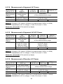
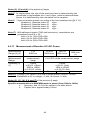
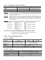
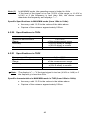
This mode is used to determine the phase order of a 3-phase network using the
"2-wire" method.
To determine the phase order, proceed as follows:
Step 1: Determining the Reference Period:
1.
Set the switch to
. The rdy symbol is displayed; the device is
ready for the first phase order determination measurement.
2.
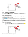
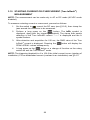
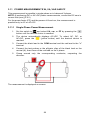
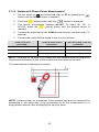
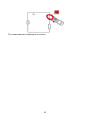
Connect the black lead with alligator clip to the COM terminal and the
red lead with the test probe to the "+" terminal.
3.
Connect the alligator clip to the presumed L1 phase and apply the red
test probe to the presumed L2 phase.
4.
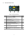
Press the
(yellow) button. The ref symbol blinks on the screen.
The instrument is ready to determine the reference period. When the
reference period has been determined, an audible signal sounds and
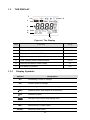
the ref and
symbols are displayed.
NOTE: If the reference period has not been determined, the device emits a beep
and displays the "Err Hz" or "ErrV" message. The
symbol flashes, then the
"rdy" message is displayed on the screen. Repeat the procedure from Step 4.
Step 2: Determining the Measurement Period:
1.
Within the next 10 seconds, apply the test probe to the presumed L3
phase. The "MEAS" symbol blinks on the display as soon as the L2
phase is disconnected. The device is now in the calculation phase.
NOTE: If the measurement period has not been determined, the device emits a
beep and displays the "Err Hz" or "ErrV" message, then "rdy". Repeat the
procedure from Step 4.
Result: When the phase order has been determined, the device emits a beep
and the indication of order of the phases is displayed on the screen, as follows:
•
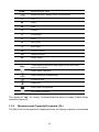
0.1.2.3 when the direction of rotation is direct. The "0" symbol blinks and
turns clockwise;
•
0.3.2.1 when the direction of rotation is reversed. The "0" symbol blinks
and turns anticlockwise.
NOTE: If the phase order has not been determined, the device emits a beep and
displays the "Err" message. Repeat the procedure from Step 4.
31