1
USER GUIDE
Jeep.com (U.S.)
Jeep.ca (Canada)
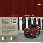
Download a FREE electronic copy of the
Owner’s Manual and Warranty Booklet by visiting:
www.jeep.com/en/owners/manuals or www.jeep.com/en/warranty (U.S.);
www.owners.mopar.ca/en (Canada).
© 2015 FCA US LLC. All Rights Reserved.
Jeep and Renegade are registered trademarks of FCA US LLC.
15BU-926-AA
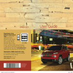
Renegade
Third Edition
User Guide
1981792_15c_Renegade_UG_062415.indd 1
2015
Renegade
6/24/15 4:56 PM
If you are the first registered retail owner of
your vehicle, you may obtain a complimentary
printed copy of the Owner’s Manual, Navigation/
Uconnect Manuals or Warranty Booklet by calling
1-877-426-5337 (U.S.) or 1-800-387-1143 (Canada)
or by contacting your dealer.
This guide has been prepared to help you get quickly
acquainted with your new Jeep and to provide a
®
convenient reference source for common questions.
However, it is not a substitute for your Owner’s Manual.
For complete operational instructions, maintenance
procedures and important safety messages, please consult
your Owner’s Manual, Navigation/Uconnect Manuals and
other Warning Labels in your vehicle.
Not all features shown in this guide may apply to your
vehicle. For additional information on accessories to help
personalize your vehicle, visit www.mopar.com (U.S.),
www.mopar.ca (Canada) or your local Jeep dealer.
The driver’s primary responsibility is the safe operation of the vehicle.
Driving while distracted can result in loss of vehicle control, resulting in
a collision and personal injury. FCA US LLC strongly recommends that
the driver use extreme caution when using any device or feature that
may take their attention off the road. Use of any electrical devices, such
as cellular telephones, computers, portable radios, vehicle navigation
or other devices, by the driver while the vehicle is moving is dangerous
and could lead to a serious collision. Texting while driving is also
dangerous and should never be done while the vehicle is moving. If you
find yourself unable to devote your full attention to vehicle operation,
pull off the road to a safe location and stop your vehicle. Some states or
provinces prohibit the use of cellular telephones or texting while driving.
It is always the driver’s responsibility to comply with all local laws.
Important:
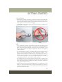
Driving and Alcohol:
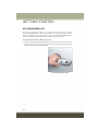
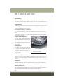
This User Guide is intended to familiarize you with the important features
of your vehicle. The DVD enclosed contains your Owner’s Manual,
Navigation/Uconnect Manuals, Warranty Booklets, Tire Warranty and
Roadside Assistance (new vehicles purchased in the U.S.) or Roadside
Assistance (new vehicles purchased in Canada) in electronic format.
We hope you find it useful. Replacement DVD kits may be purchased by
visiting www.techauthority.com.
Drunken driving is one of the most frequent causes of collisions. Your
driving ability can be seriously impaired with blood alcohol levels far below
the legal minimum. If you are drinking, don’t drive. Ride with a designated
non-drinking driver, call a cab, a friend, or use public transportation.
WAR N I NG !
Driving after drinking can lead to a collision. Your perceptions are
less sharp, your reflexes are slower, and your judgment is impaired
when you have been drinking. Never drink and then drive.
1981792_15c_Renegade_UG_062415.indd 2
6/24/15 4:56 PM
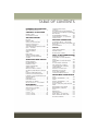
TABLE OF CONTENTS
INTRODUCTION/WELCOME
WELCOME FROM FCA US LLC
...... 3
CONTROLS AT A GLANCE
DRIVER COCKPIT . . . . . . . . . . . . . . 6
INSTRUMENT CLUSTER . . . . . . . . . . 8
GETTING STARTED
KEY FOB . . . . . . . . . . . . . . . . . .
REMOTE START . . . . . . . . . . . . . .
VEHICLE SECURITY ALARM . . . . . .
KEYLESS ENTER-N-GO™ . . . . . . . .
SEAT BELT SYSTEMS . . . . . . . . . .
SUPPLEMENTAL RESTRAINT SYSTEM
(SRS) — AIR BAGS . . . . . . . . . . .
CHILD RESTRAINTS . . . . . . . . . . .
HEAD RESTRAINTS . . . . . . . . . . . .
SEATS . . . . . . . . . . . . . . . . . . . .
REAR SEATS . . . . . . . . . . . . . . .
HEATED STEERING WHEEL . . . . . . .
TILT/TELESCOPING STEERING
COLUMN . . . . . . . . . . . . . . . . . .
STEERING WHEEL AUDIO
CONTROLS . . . . . . . . . . . . . . . . . 137
ELECTRONIC VEHICLE INFORMATION
CENTER (EVIC) AND DRIVER INFORMATION
DISPLAY (DID) . . . . . . . . . . . . . . . 138
PROGRAMMABLE FEATURES . . . . . . 146
POWER INVERTER — IF EQUIPPED . . 146
POWER OUTLET . . . . . . . . . . . . . . 147
.
.
.
.
.
10
12
13
14
17
OFF-ROAD CAPABILITIES
.
.
.
.
.
.
18
22
26
27
30
32
UTILITY
. 33
OPERATING YOUR VEHICLE
ENGINE BREAK-IN
RECOMMENDATIONS . . . . . . . . . . .
EXTERIOR LIGHTS . . . . . . . . . . . . .
WIPERS AND WASHERS . . . . . . . . . .
SPEED CONTROL . . . . . . . . . . . . . .
MANUAL CLIMATE CONTROLS . . . . . .
AUTOMATIC TEMPERATURE CONTROLS
(ATC) . . . . . . . . . . . . . . . . . . . . . .
ELECTRIC PARK BRAKE (EPB) . . . . . .
BLIND SPOT MONITORING (BSM) . . . .
FORWARD COLLISION WARNING (FCW)
WITH MITIGATION . . . . . . . . . . . . .
LANESENSE . . . . . . . . . . . . . . . . .
REAR PARK ASSIST . . . . . . . . . . . .
REAR BACK UP CAMERA . . . . . . . . .
MY SKY SUN ROOF — IF EQUIPPED . .
34
34
37
39
42
43
44
46
50
54
58
62
63
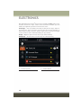
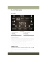
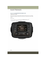
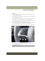
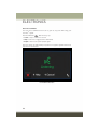
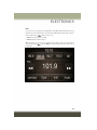
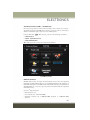
ELECTRONICS
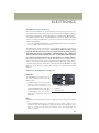
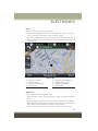
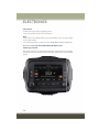
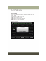
YOUR VEHICLE'S SOUND SYSTEM . . . 72
IDENTIFYING YOUR RADIO . . . . . . . . 74
Uconnect® ACCESS . . . . . . . . . . . . . 75
Uconnect® 3.0 . . . . . . . . . . . . . . . . 88
Uconnect® 5.0 . . . . . . . . . . . . . . . . 90
Uconnect® 6.5AN . . . . . . . . . . . . . 103
Uconnect® PHONE . . . . . . . . . . . . 126
FOUR WHEEL DRIVE — JEEP ACTIVE
DRIVE (4WD) AND JEEP ACTIVE DRIVE LOW
(4WD LOW) . . . . . . . . . . . . . . . . . 150
SELEC-TERRAIN™ . . . . . . . . . . . . 152
CARGO AREA FEATURES . . . . . . . . 153
TRAILER TOWING . . . . . . . . . . . . 153
RECREATIONAL TOWING . . . . . . . . 154
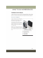
WHAT TO DO IN EMERGENCIES
ROADSIDE ASSISTANCE . . . . . . . .
INSTRUMENT CLUSTER WARNING
LIGHTS . . . . . . . . . . . . . . . . . .
INSTRUMENT CLUSTER INDICATOR
LIGHTS . . . . . . . . . . . . . . . . . .
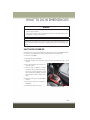
IF YOUR ENGINE OVERHEATS . . . .
TIRE SERVICE KIT STORAGE . . . . .
JACKING AND TIRE CHANGING . . .
JUMP STARTING . . . . . . . . . . . . .
FREEING A STUCK VEHICLE . . . . .
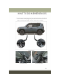
EMERGENCY TOW HOOKS . . . . . .
SHIFT LEVER OVERRIDE . . . . . . .
TOWING A DISABLED VEHICLE . . .
. 156
. 156
.
.
.
.
.
.
.
.
.
162
164
165
168
174
177
178
179
180
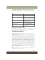
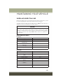
MAINTAINING YOUR VEHICLE
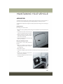
HOOD . . . . . . . . . . . . . . . . . . . .
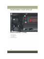
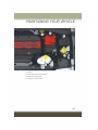
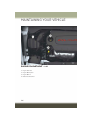
ENGINE COMPARTMENT — 1.4L
TURBO . . . . . . . . . . . . . . . . . . .
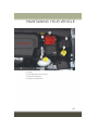
ENGINE COMPARTMENT — 2.4L . . .
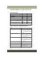
FLUID CAPACITIES . . . . . . . . . . . .
FLUIDS, LUBRICANTS, AND GENUINE
PARTS . . . . . . . . . . . . . . . . . . . .
MAINTENANCE PROCEDURES . . . . .
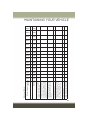
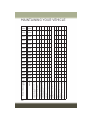
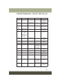
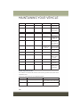
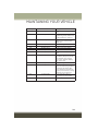
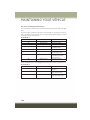
MAINTENANCE SCHEDULE . . . . . . .
FUSES . . . . . . . . . . . . . . . . . . . .
ADDING FUEL . . . . . . . . . . . . . . .
TIRE PRESSURES . . . . . . . . . . . . .
SPARE TIRES — IF EQUIPPED . . . . .
WHEEL AND WHEEL TRIM CARE . . .
BULB REPLACEMENT . . . . . . . . . .
182
184
186
188
188
189
189
196
201
202
203
205
205
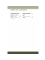
TABLE OF CONTENTS
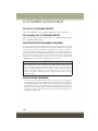
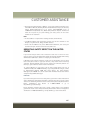
CUSTOMER ASSISTANCE
FCA US LLC CUSTOMER CENTER . . .
FCA CANADA INC. CUSTOMER
CENTER . . . . . . . . . . . . . . . . . .
ASSISTANCE FOR THE HEARING
IMPAIRED . . . . . . . . . . . . . . . . .
PUBLICATIONS ORDERING . . . . . . .
REPORTING SAFETY DEFECTS IN THE
UNITED STATES . . . . . . . . . . . . . .
2
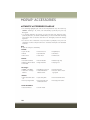
MOPAR® ACCESSORIES
206
206
206
206
207
AUTHENTIC ACCESSORIES BY
MOPAR® . . . . . . . . . . . . . . . . . . 208
FAQ’s
FREQUENTLY ASKED QUESTIONS
. . 209
INDEX . . . . . . . . . . . . . . . . . . . 211
INTRODUCTION/WELCOME
WELCOME FROM FCA US LLC
Congratulations on selecting your new FCA US LLC (“FCA US”) vehicle. Be assured
that it represents precision workmanship, distinctive styling, and high quality - all
essentials that are traditional to our vehicles.
Your new FCA US vehicle has characteristics to enhance the driver's control under
some driving conditions. These are to assist the driver and are never a substitute for
attentive driving. They can never take the driver's place. Always drive carefully.
Your new vehicle has many features for the comfort and convenience of you and your
passengers. Some of these should not be used when driving because they take your
eyes from the road or your attention from driving. Never text while driving or take your
eyes more than momentarily off the road.
This guide illustrates and describes the operation of features and equipment that are
either standard or optional on this vehicle. This guide may also include a description
of features and equipment that are no longer available or were not ordered on this
vehicle. Please disregard any features and equipment described in this guide that are
not available on this vehicle. FCA US reserves the right to make changes in design
and specifications and/or make additions to or improvements to its products without
imposing any obligation upon itself to install them on products previously manufactured.
This User Guide has been prepared to help you quickly become acquainted with the
important features of your vehicle. It contains most things you will need to operate
and maintain the vehicle, including emergency information.
The DVD includes a computer application containing detailed owner's information
which can be viewed on a personal computer or MAC computer. The multimedia DVD
also includes videos which can be played on any standard DVD player (including the
Uconnect Touchscreen Radios if equipped with DVD player capabilities). Additional
DVD operational information is located on the back of the DVD sleeve.
For complete owner information, refer to your Owner's Manual on the DVD in the owner’s
kit provided at the time of new vehicle purchase. For your convenience, the information
contained on the DVD may also be printed and saved for future reference.
FCA US is committed to protecting our environment and natural resources. By
converting from paper to electronic delivery for the majority of the user information
for your vehicle, together we greatly reduce the demand for tree-based products and
lessen the stress on our environment.
3
INTRODUCTION/WELCOME
VEHICLES SOLD IN CANADA
With respect to any vehicles sold in Canada, the name FCA US LLC shall be deemed
to be deleted and the name FCA Canada Inc. used in substitution (excluding legal
lines).
WARNING!
• Pedals that cannot move freely can cause loss of vehicle control and increase
the risk of serious personal injury.
• Always make sure that objects cannot fall into the driver foot well while the
vehicle is moving. Objects can become trapped under the brake pedal and
accelerator pedal causing a loss of vehicle control.
• Failure to properly follow floor mat installation or mounting can cause interference with the brake pedal and accelerator pedal operation causing loss of
control of the vehicle.
• Never leave children alone in a vehicle, or with access to an unlocked vehicle.
Allowing children to be in a vehicle unattended is dangerous for a number of
reasons. A child or others could be seriously or fatally injured. Children should
be warned not to touch the parking brake, brake pedal or the shift lever.
• Do not leave the key fob in or near the vehicle, or in a location accessible to
children, and do not leave the ignition of a vehicle equipped with Keyless
Enter-N-Go in the MAR/RUN mode. A child could operate power windows,
other controls, or move the vehicle.
• Never use the “PARK” position as a substitute for the parking brake. Always
apply the parking brake fully when parked to guard against vehicle movement
and possible injury or damage.
• Refer to your Owner's Manual on the DVD for further details.
4
INTRODUCTION/WELCOME
Rollover Warning
WARNING!
• Pedals that cannot move freely can cause loss of vehicle control and increase
the risk of serious personal injury.
• Always make sure that objects cannot fall into the driver foot well while the
vehicle is moving. Objects can become trapped under the brake pedal and
accelerator pedal causing a loss of vehicle control.
• Failure to properly follow floor mat installation or mounting can cause interference with the brake pedal and accelerator pedal operation causing loss of
control of the vehicle.
• Refer to your Owner's Manual on the DVD for further details.
• Never use the ‘PARK’ position as a substitute for the parking brake. Always
apply the parking brake fully when parked to guard against vehicle movement
and possible injury or damage.
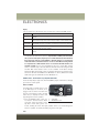
USE OF AFTERMARKET PRODUCTS (ELECTRONICS)
The use of aftermarket devices including cell phones, MP3 players, GPS systems, or
chargers may affect the performance of on-board wireless features including Keyless
Enter-N-Go and Remote Start range. If you are experiencing difficulties with any of
your wireless features, try disconnecting your aftermarket devices to see if the
situation improves. If your symptoms persist, please see an authorized dealer.
When it comes to service, remember that your authorized dealer knows your Jeep®
vehicle best, has factory-trained technicians and genuine MOPAR® parts, and cares
about your satisfaction.
JEEP is a registered trademark of FCA US LLC.
5
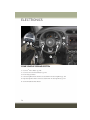
CONTROLS AT A GLANCE
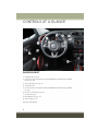
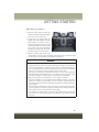
DRIVER COCKPIT
1. Headlight Switch pg. 34
2. Electronic Vehicle Information Center (EVIC) Or Driver Information Display (DID)
Controls pg. 138
3. Turn Signal/Light Lever pg. 37
4. Tachometer pg. 8
5. Electronic Vehicle Information Center (EVIC) Or Driver Information Display (DID)
pg. 138
6. Electronic Speed Control pg. 39
7. Speedometer pg. 8
8. Wiper/Washer Lever pg. 37
9. Audio System pg. 72
10. Glove Compartment
6
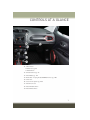
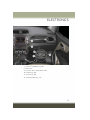
CONTROLS AT A GLANCE
11. Switch Panel
• ParkSense® pg. 58
• Hazard Switch
12. Climate Controls pg. 43
13. Power Outlet pg. 147
14. Media Hub – Playing iPod®/USB/MP3/ Devices pg. 108
15. Shift Lever
16. Selec-Terrain System pg. 150
17. Power Door Locks
18. Power Window Switch
19. Power Mirror Switch
7
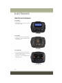
CONTROLS AT A GLANCE
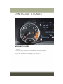
INSTRUMENT CLUSTER
1. Tachometer
2. Electronic Vehicle Information Center (EVIC) Or Driver Information Display (DID)
3. Temperature Gauge
(See page 156 for Instrument Cluster Warning Lights information.)
8
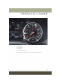
CONTROLS AT A GLANCE
4. Gear Position
5. Speedometer
6. Fuel Gauge
7. Fuel Filler Door Location
(See page 162 for Instrument Cluster Indicator Lights information.)
9
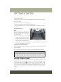
GETTING STARTED
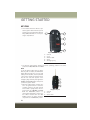
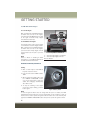
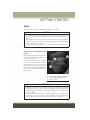
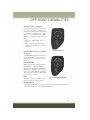
KEY FOB
• This feature allows the driver to operate the ignition switch with the push of
a button as long as the Remote Keyless
Entry (RKE) transmitter is in the passenger compartment.
Keyless Enter-N-Go Key Fob
1
2
3
4
5
—
—
—
—
—
Unlock
Lock
Remote Start
Panic
Emergency Key
• The Keyless Push Button Ignition has three operating positions. The three
positions are OFF, ON/RUN and START.
NOTE:
In case the ignition switch does not change
with the push of a button, the RKE transmitter (Key Fob) may have a low or dead
battery. In this situation, a back up method
can be used to operate the ignition switch.
Put the nose side (side opposite of the
emergency key) of the Key Fob against the
ENGINE START/STOP button and push to
operate the ignition switch.
• Mechanical Key Ignition operates similar to an ignition switch. It has three
operating positions, two with detents
and one that is spring-loaded. The detent positions are STOP/OFF and MAR/
RUN. The AVV/START position is a
spring-loaded momentary contact position. When released from the AVV/
START position, the switch automatically returns to the MAR/RUN position.
10
Integrated Key fob
1 — Unlock
2 — Lock
3 — Panic Hold
GETTING STARTED
Locking And Unlocking The Doors/Liftgate
• Push LOCK button once to lock all the doors and the liftgate. Push UNLOCK
button once to unlock the driver’s door only and twice within five seconds to unlock
all the doors and the liftgate.
• All doors can be programmed to unlock on the first push of the UNLOCK button.
Refer to “Uconnect® Programmable Features” in this guide for further
information.
Panic Alarm
• Push and hold the PANIC button for one second to turn the panic alarm on.
• Wait approximately three seconds and push the button a second time to turn the
panic alarm off.
NOTE:
• Never use the PARK position as a substitute for the parking brake. Always apply
the parking brake fully when parked to guard against vehicle movement and
possible injury or damage.
• When leaving the vehicle, always remove the key fob from the ignition and lock
your vehicle. If equipped with Keyless Enter-N-Go, always make sure the keyless
ignition node is in “OFF” mode, remove the Key Fob from the vehicle and lock the
vehicle.
• Never leave children alone in a vehicle, or with access to an unlocked vehicle.
Allowing children to be in a vehicle unattended is dangerous for a number of
reasons. A child or others could be seriously or fatally injured. Children should be
warned not to touch the parking brake, brake pedal or the transmission gear
selector.
• Do not leave the Key Fob in or near the vehicle (or in a location accessible to
children), and do not leave the ignition of a vehicle equipped with Keyless
Enter-N-Go in the ON/RUN mode. A child could operate power windows, other
controls, or move the vehicle.
11
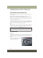
GETTING STARTED
REMOTE START
This system uses the Remote Keyless Entry (RKE) transmitter to start the engine
conveniently from outside the vehicle while still maintaining security. The system has
a range of at least 300 ft (91 m).
The Remote Starting System also activates the Climate Control and (if equipped) the
optional heated seats and optional heated steering wheel depending on temperatures
outside and inside the car.
• Push REMOTE START button
on the Key Fob twice within five seconds.
Pushing the REMOTE START button a third time shuts the engine off.
• To drive the vehicle, push UNLOCK button, insert the key (in case of Integrated
Key) in the ignition and turn to the MAR/RUN position.
• With Remote Start, the engine will only run for 15 minutes (timeout) unless the
ignition key is placed in the MAR/RUN position.
• The vehicle must be started with the mechanical key or Key Fob after two
consecutive timeouts.
NOTE:
The Remote Start Comfort System can be activated and deactivated through the
Uconnect® Settings. Refer to “Uconnect® Programmable Features” in “Electronics”
for more information on Remote Start Comfort System operation.
WARNING!
• Do not start or run an engine in a closed garage or confined area. Exhaust gas
contains Carbon Monoxide (CO) which is odorless and colorless. Carbon
Monoxide is poisonous and can cause serious injury or death when inhaled.
• Keep Key Fob transmitters away from children. Operation of the Remote Start
System, windows, door locks or other controls could cause serious injury or
death.
Remote Start Windshield Wiper De–icer Activation — If Equipped
When Remote Start is active and the outside ambient temperature is less than 40° F
(4.4° C), the wiper De-Icer will be enabled. On exiting Remote Start, resume the
previous operation except if the De-Icer is active; the De-Icer timer and operation will
continue.
12
GETTING STARTED
VEHICLE SECURITY ALARM
The Vehicle Security Alarm monitors the vehicle doors for unauthorized entry and the
Keyless Enter-N-Go™ START/STOP button for unauthorized operation. While the
Vehicle Security Alarm is armed, interior switches for door locks and decklid release
are disabled. If something triggers the alarm, the Vehicle Security Alarm will provide
the following audible and visible signals: the horn will pulse, the park lamps and/or
turn signals will flash, and the Vehicle Security Light in the instrument cluster will
flash.
To Arm:
Lock the door using either the power door lock switch (one door must be open) or the
LOCK button on the Remote Keyless Entry (RKE) transmitter (doors can be open or
closed), and close all doors.
The Vehicle Security Light in the instrument cluster will flash for 16 seconds. This
shows that the Vehicle Security Alarm is arming. During this period, if a door is
opened, the ignition is cycled to MAR/RUN, or the power door locks are unlocked in
any manner, the Vehicle Security Alarm will automatically disarm.
NOTE:
• The Vehicle Security Alarm will not arm if you lock the doors with the manual door
lock plungers.
• Once armed, the Vehicle Security Alarm disables the unlock switch on the driver
door trim panel and passenger door trim panel.
To Disarm The System:
Push the Key Fob UNLOCK button or cycle the ignition to the MAR/RUN position.
The Vehicle Security Alarm is designed to protect your vehicle. However, you can
create conditions where the Vehicle Security Alarm will give you a false alarm. If one
of the previously described arming sequences has occurred, the Vehicle Security
Alarm will arm regardless of whether you are in the vehicle or not. If you remain in the
vehicle and open a door, the alarm will sound. If this occurs, disarm the Vehicle
Security Alarm.
If the Vehicle Security Alarm is armed and the battery becomes disconnected, the
Vehicle Security Alarm will remain armed when the battery is reconnected. The
exterior lights will flash, and the horn will sound. If this occurs, disarm the Vehicle
Security Alarm.
13
GETTING STARTED
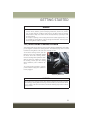
KEYLESS ENTER-N-GO™
The Keyless Enter-N-Go™ system is an enhancement to the vehicle’s Remote
Keyless Entry (RKE) feature. This feature allows you to lock and unlock the vehicle's
door(s) and liftgate without having to push the Key Fob LOCK or UNLOCK buttons,
as well as starting and stopping the vehicle with the push of a button.
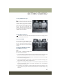
To Unlock From The Driver Or Passenger Side:
• With a valid Keyless Enter-N-Go™ Key Fob located outside the vehicle and within
5 ft (1.5 m) of the driver or passenger side door handle, grab either front door
handle to unlock the door automatically.
Grab The Door Handle To Unlock
14
GETTING STARTED
To Lock The Vehicle:
• Both front door handles have buttons located on the outside of the handle. With
one of the vehicle’s Keyless Enter-N-Go™ Key Fobs located outside the vehicle
and within 5 ft (1.5m) of the driver's or passenger front door handle, push the door
handle button to lock all four doors and liftgate.
• Do NOT grab the door handle when pushing the door handle lock button. This
could unlock the door(s).
Push The Door Handle Button To Lock
Do NOT Grab The Handle And Button When
Locking
NOTE:
• If “Unlock All Doors 1st Push” is programmed, all doors will unlock when you grab
hold of the front driver's door handle. To select between “Unlock Driver Door 1st
Push” and “Unlock All Doors 1st Push,” refer to the “Uconnect® Settings” in your
vehicle’s Owner's Manual on the DVD or “Programmable Features” in this guide for
further information.
• If “Unlock All Doors 1st Push” is programmed, all doors and liftgate will unlock
when you push the liftgate button. If “Unlock Driver Door 1st Push” is programmed, only the liftgate will unlock when you push the liftgate button. To select
between “Unlock Driver Door 1st Push” and “Unlock All Doors 1st Push,” refer to
the “Uconnect® Settings” in your vehicle's Owner's Manual on the DVD or
“Programmable Features” in this guide for further information.
• If a Key Fob is detected in the vehicle when locking the vehicle using the power
door lock switch, the doors and liftgate will unlock and the horn will chirp three
times. On the third attempt of pushing the door handle lock button, your Key Fob
can be locked inside the vehicle.
• After pushing the Keyless Enter-N-Go™ LOCK button, you must wait two seconds
before you can lock or unlock the vehicle using the door handle. This is done to
allow you to check if the vehicle is locked by pulling the door handle without the
vehicle reacting and unlocking.
15
GETTING STARTED
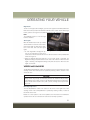
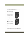
Lock Or Unlock The Liftgate
To Lock The Liftgate
With a valid Passive Entry RKE transmitter within 5 ft (1.5 m) of the liftgate,
push Passive Entry LOCK button located
to the right of Passive Entry liftgate
unlock/release button (2).
To Unlock/Enter The Liftgate
The liftgate passive entry unlock feature
is built into the electronic liftgate handle.
With a valid passive entry RKE transmitter within 5 ft (1.5 m) of the liftgate,
push the Passive Entry liftgate unlock/
release button (2) and pull to open the
liftgate.
NOTE:
Refer to “Doors” in “Getting To Know
Your Vehicle” in your Owner's Manual on
the DVD for further information.
Passive Entry Button to Lock/Unlock
1 — Passive Entry Liftgate Lock Button
2 — Passive Entry Liftgate Unlock/
Release Button
ENGINE STARTING/STOPPING
Starting
1. With a valid Keyless Enter-N-Go™
Key Fob inside the vehicle.
2. Place the shift lever in PARK or NEUTRAL.
3. While pushing the brake pedal, push
the ENGINE START/STOP button
once. If the engine fails to start, the
starter will disengage automatically
after 10 seconds.
4. To stop the cranking of the engine
prior to the engine starting, push the
button again.
Engine Start/Stop Button
NOTE:
In case the ignition switch does not change with the push of a button, the RKE
transmitter (Key Fob) may have a low or dead battery. In this situation, a back up
method can be used to operate the ignition switch. Put the nose side of the Key Fob
against the ENGINE START/STOP button and push to operate the ignition switch.
16
GETTING STARTED
Stopping
1. Place the shift lever in PARK.
2. Push the ENGINE START/STOP button once. The ignition switch will return to the
OFF position.
NOTE:
If the shift lever is not in PARK, the ENGINE START/STOP button must be held for two
seconds and vehicle speed must be above 5 MPH (8 km/h) before the engine will shut off.
RUN Position With Engine Off
NOTE:
The following functions are with the driver’s foot OFF the Brake Pedal (Transmission
in PARK or NEUTRAL Position).
Starting With The Ignition Switch In The OFF Position:
1. Push the ENGINE START/STOP button once to change the ignition switch to the
RUN position.
2. Push the ENGINE START/STOP button a second time to return the ignition switch
to the OFF position.
NOTE:
If the ignition switch is left in the RUN (engine not running) position and the
transmission is in PARK, the system will automatically time out after 30 minutes of
inactivity and the ignition will switch to the OFF position.
In case the ignition switch does not change with the push of a button, the RKE
transmitter (Key Fob) may have a low or dead battery. In this situation, a back up
method can be used to operate the ignition switch. Put the nose side (side opposite
of the emergency key) of the Key Fob against the ENGINE START/STOP button and
push to operate the ignition switch.
SEAT BELT SYSTEMS
Lap/Shoulder Belts
• All seating positions in your vehicle are equipped with lap/shoulder belts.
• Be sure everyone in your vehicle is in a seat and using a seat belt properly.
• Position the lap belt so that it is snug and lies low across your hips, below your
abdomen. To remove slack in the lap belt portion, pull up on the shoulder belt. To
loosen the lap belt if it is too tight, tilt the latch plate and pull on the lap belt. A
snug seat belt reduces the risk of sliding under the seat belt in a collision.
• Position the shoulder belt across the shoulder and chest with minimal, if any slack
so that it is comfortable and not resting on your neck. The retractor will withdraw
any slack in the shoulder belt.
17
GETTING STARTED
Seat Belt Pretensioner
• The front seat belt system is equipped with pretensioning devices that are
designed to remove slack from the seat belt in the event of a collision.
• A deployed pretensioner or a deployed air bag must be replaced immediately.
WARNING!
• In a collision, you and your passengers can suffer much greater injuries if you
are not properly buckled up. You can strike the interior of your vehicle or other
passengers, or you can be thrown out of the vehicle. Always be sure you and
others in your vehicle are buckled up properly.
• A shoulder belt placed behind you will not protect you from injury during a
collision. You are more likely to hit your head in a collision if you do not wear
your shoulder belt. The lap and shoulder belt are meant to be used together.
• A seat belt that is too loose will not protect you properly. In a sudden stop, you
could move too far forward, increasing the possibility of injury. Wear your seat
belt snugly.
• A frayed or torn seat belt could rip apart in a collision and leave you with no
protection. Inspect the seat belt system periodically, checking for cuts, frays,
or loose parts. Damaged parts must be replaced immediately. Do not disassemble or modify the system. Seat belt assemblies must be replaced after a
collision.
SUPPLEMENTAL RESTRAINT SYSTEM (SRS) — AIR
BAGS
Air Bag System Components
Your vehicle may be equipped with the following air bag system components:
• Occupant Restraint Controller (ORC)
• Air Bag Warning Light
• Steering Wheel and Column
• Instrument Panel
• Knee Impact Bolsters
• Advanced Front Air Bags
• Supplemental Side Air Bags
• Supplemental Knee Air Bags
• Front and Side Impact Sensors
• Seat Belt Pretenioners
• Seat Belt Buckle Switch
• Seat Track Position Sensors
18
GETTING STARTED
Advanced Front Air Bags
• This vehicle has Advanced Front Air Bags for both the driver and front passenger
as a supplement to the seat belt restraint systems. The Advanced Front Air Bags
will not deploy in every type of collision.
• Advanced Front Air Bags are designed to provide additional protection by
supplementing the seat belts. Advanced Front Air Bags are not expected to reduce
the risk of injury in rear, side, or rollover collisions.
• The Advanced Front Air Bags will not deploy in all frontal collisions, including
some that may produce substantial vehicle damage — for example, some pole
collisions, truck underrides, and angle offset collisions.
• On the other hand, depending on the type and location of impact, Advanced Front
Air Bags may deploy in crashes with little vehicle front-end damage but that
produce a severe initial deceleration.
• Because air bag sensors measure vehicle deceleration over time, vehicle speed
and damage by themselves are not good indicators of whether or not an air bag
should have deployed.
• Seat belts are necessary for your protection in all collisions, and also are needed
to help keep you in position, away from an inflating air bag.
• The air bags must be ready to inflate for your protection in a collision. The
Occupant Restraint Controller (ORC) monitors the internal circuits and interconnecting wiring associated with air bag system electrical components.
• The ORC turns on the Air Bag Warning Light in the instrument panel for
approximately four to eight seconds for a self-check when the ignition switch is
first turned to the MAR/RUN position. After the self-check, the Air Bag Warning
Light will turn off. If the ORC detects a malfunction in any part of the system, it
turns on the Air Bag Warning Light, either momentarily or continuously. A single
chime will sound to alert you if the light comes on again after initial startup.
• The ORC monitors the readiness of the electronic parts of the air bag system
whenever the ignition switch is in the AVV/START or MAR/RUN position. If the
ignition switch is in the STOP/OFF position, the air bag system is not on and the
air bags will not inflate.
• If the Air Bag Warning Light in the instrument panel is not on during the four to
eight seconds when the ignition switch is first turned to the MAR/RUN position,
stays on, or turns on while driving, have the vehicle serviced by an authorized
service center immediately.
NOTE:
If the speedometer, tachometer, or any engine related gauges are not working, the
Occupant Restraint Controller (ORC) may also be disabled. In this condition the air
bags may not be ready to inflate for your protection. Have an authorized dealer
service the air bag system immediately.
• After any collision, the vehicle should be taken to an authorized dealer immediately.
19
GETTING STARTED
• Do not drive your vehicle after the air bags have deployed. If you are involved in
another collision, the air bags will not be in place to protect you.
• If it is necessary to modify the air bag system for persons with disabilities, contact
your authorized dealer.
• Refer to “Supplemental Restraint System (SRS)” in “Safety” in the Owner's
Manual on the DVD for further information.
Supplemental Knee Air Bags
This vehicle is equipped with a Supplemental Driver Knee Air Bag mounted in the
instrument panel below the steering column. The Supplemental Driver Knee Air Bag
provides enhanced protection during a frontal impact by working together with the
seat belts, pretensioners, and Advanced Front Air Bags.
WARNING!
• Relying on the air bags alone could lead to more severe injuries in a collision.
The air bags work with your seat belt to restrain you properly. In some
collisions, the air bags won't deploy at all. Always wear your seat belts even
though you have air bags.
• Being too close to the steering wheel or instrument panel during Advanced
Front Air Bag deployment could cause serious injury, including death. Air bags
need room to inflate. Sit back, comfortably extending your arms to reach the
steering wheel or instrument panel.
• No objects should be placed over or near the air bag on the instrument panel
or steering wheel because any such objects could cause harm if the vehicle is
in a collision severe enough to cause the air bag to inflate.
Supplemental Side Air Bags
• This vehicle is equipped with Supplemental Seat-Mounted Side Air Bags (SABs)
located in the outboard side of the front seats. The SABs are marked with a SRS
AIRBAG or AIRBAG label sewn into the outboard side of the seats.
• This vehicle is equipped with Supplemental Side Air Bag Inflatable Curtains
(SABICs) located above the side windows. The trim covering the SABICs is labeled
SRS AIRBAG or AIRBAG. The SABICs may help reduce the risk of partial or
complete ejection of vehicle occupants through side windows in certain side
impact events.
• The SABICs and SABs (“Side Air Bags”) are designed to activate in certain side
impacts and certain rollover events. The Occupant Restraint Controller (“ORC”)
determines whether the deployment of the Side Air Bags in a particular side
impact or rollover event is appropriate, based on the severity and type of collision.
Vehicle damage by itself is not a good indicator of whether or not Side Air Bags
should have deployed.
20
GETTING STARTED
WARNING!
• Side Air Bags need room to inflate. Do not lean against the door or window. Sit
upright in the center of the seat.
• Being too close to the Side Air Bags during deployment could cause you to be
severely injured or killed.
• Relying on the Side Air Bags alone could lead to more severe injuries in a
collision. The Side Air Bags work with your seat belt to restrain you properly. In
some collisions, Side Air Bags won’t deploy at all. Always wear your seat belt
even though you have Side Air Bags.
• This vehicle is equipped with left and right Supplemental Side Air Bag
Inflatable Curtains (SABICs). Do not stack luggage or other cargo up high
enough to block the deployment of the SABICs. The trim covering above the
side windows where the SABIC and its deployment path are located should
remain free from any obstructions.
• This vehicle is equipped with SABICs. In order for the SABICs to work as
intended, do not install any accessory items in your vehicle which could alter
the roof. Do not add an aftermarket sunroof to your vehicle. Do not add roof
racks that require permanent attachments (bolts or screws) for installation on
the vehicle roof. Do not drill into the roof of the vehicle for any reason.
• Do not use accessory seat covers or place objects between you and the Side Air
Bags; the performance could be adversely affected and/or objects could be
pushed into you, causing serious injury.
Event Data Recorder (EDR)
This vehicle is equipped with an event data recorder (EDR). The main purpose of an
EDR is to record, in certain crash or near crash-like situations, such as an air bag
deployment or hitting a road obstacle, data that will assist in understanding how a
vehicle’s systems performed. The EDR is designed to record data related to vehicle
dynamics and safety systems for a short period of time, typically 30 seconds or less.
The EDR in this vehicle is designed to record such data as:
• How various systems in your vehicle were operating;
• Whether or not the driver and passenger safety belts were buckled/fastened;
• How far (if at all) the driver was depressing the accelerator and/or brake pedal;
and,
• How fast the vehicle was traveling.
21
GETTING STARTED
These data can help provide a better understanding of the circumstances in which
crashes and injuries occur.
NOTE:
EDR data are recorded by your vehicle only if a non-trivial crash situation occurs; no
data are recorded by the EDR under normal driving conditions and no personal data
(e.g., name, gender, age, and crash location) are recorded. However, other parties,
such as law enforcement, could combine the EDR data with the type of personally
identifying data routinely acquired during a crash investigation.
To read data recorded by an EDR, special equipment is required, and access to the
vehicle or the EDR is needed. In addition to the vehicle manufacturer, other parties,
such as law enforcement, that have the special equipment, can read the information
if they have access to the vehicle or the EDR.
CHILD RESTRAINTS
Children 12 years or younger should ride properly buckled up in a rear seat, if
available. According to crash statistics, children are safer when properly restrained in
the rear seats rather than in the front.
Every state in the United States and all Canadian provinces require that small
children ride in proper restraint systems. This is the law, and you can be prosecuted
for ignoring it.
NOTE:
• For additional information, refer to www.Seatcheck.org or call 1-866SEATCHECK (1-866-732-8243 ).
• Canadian residents should refer to Transport Canada’s website for additional information:
http://www.tc.gc.ca/eng/motorvehiclesafety/safedrivers-childsafety-index-53.htm
LATCH – Lower Anchors And Tethers For CHildren
• Your vehicle is equipped with the child restraint anchorage system called LATCH,
which stands for Lower Anchors and Tethers for CHildren.
• The rear outboard seating positions have lower anchors and top tether anchors.
The rear center seating position has a top tether anchor only.
LATCH System Weight Limit
You may use the LATCH anchorage system until the combined weight of the child and
the child restraint is 65 lbs (29.5 kg). Use the seat belt and tether anchor instead of
the LATCH system once the combined weight is more than 65 lbs (29.5 kg).
22
GETTING STARTED
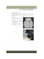
Locating LATCH Anchorages
The lower anchorages are round bars
that are found at the rear of the seat
cushion where it meets the seatback,
below the anchorage symbols on the seatback. They are just visible when you lean
into the rear seat to install the child
restraint. You will easily feel them if you
run your finger along the gap between the
seatback and seat cushion.
Lower Anchors
Locating Tether Anchorages
In addition, there are tether strap anchorages behind each rear seating position
located on the back of the seat.
Center Seat LATCH
Do not install a child restraint in the
center position using the LATCH system.
Use the seat belt and tether anchor to
install a child seat in the center seating
position.
Installing The Child Restraint Using
The LATCH Lower Anchors
NOTE:
Never “share” a LATCH anchorage with
two or more child restraints.
Tether Anchors
1. Loosen the adjusters on the lower straps and on the tether strap of the child seat so that
you can more easily attach the hooks or connectors to the vehicle anchorages.
2. Attach the lower hooks or connectors of the child restraint to the lower anchorages
in the selected seating position.
3. If the child restraint has a tether strap, connect it to the top tether anchorage. See
below for directions to attach a tether anchor.
4. Tighten all of the straps as you push the child restraint rearward and downward
into the seat. Remove slack in the straps according to the child restraint
manufacturer’s instructions.
5. Test that the child restraint is installed tightly by pulling back and forth on the
child seat at the belt path. It should not move more than 1 inch (25.4 mm) in any
direction.
23
GETTING STARTED
Installing The Child Restraint Using The Vehicle Seat Belts
The seat belts in the passenger seating positions are equipped with a Switchable
Automatic Locking Retractor (ALR) that is designed to keep the lap portion of the
seat belt tight around the child restraint. Any seat belt system will loosen with time,
so check the belt occasionally, and pull it tight if necessary.
Tether Weight Limit
Always use the tether anchor when using the seat belt to install a forward facing child
restraint, up to the recommended weight limit of the child restraint.
To Install A Child Seat Using An ALR:
1. Pull enough of the seat belt webbing from the retractor to pass it through the belt
path of the child restraint. Do not twist the belt webbing in the belt path.
2. Slide the latch plate into the buckle until you hear a “click.”
3. Pull on the webbing to make the lap portion tight against the child seat.
4. To lock the seat belt, pull down on the shoulder part of the belt until you have
pulled all the seat belt webbing out of the retractor. Then, allow the webbing to
retract back into the retractor. As the webbing retracts, you will hear a clicking
sound. This means the seat belt is now in the Automatic Locking mode.
5. Try to pull the webbing out of the retractor. If it is locked, you should not be able
to pull out any webbing. If the retractor is not locked, repeat the last step.
6. Finally, pull up on any extra webbing to tighten the lap portion around the child
restraint while you push the child restraint rearward and downward into the
vehicle seat.
7. If the child restraint has a top tether strap and the seating position has a top tether
anchorage, connect the tether strap to the anchorage and tighten the tether strap.
See below for directions to attach a tether anchor.
8. Test that the child restraint is installed tightly by pulling back and forth on the
child seat at the belt path. It should not move more than 1 inch (25.4 mm) in any
direction.
Installing The Top Tether Strap (With Either Lower Anchors Or Vehicle Seat
Belt):
When installing a forward-facing child restraint, always secure the top tether strap,
up to the tether anchor weight limit, whether the child restraint is installed with the
lower anchors or the vehicle seat belt.
24
GETTING STARTED
Tether Anchorage Installation
1. Route the tether strap to provide the
most direct path for the strap between
the anchor and the child seat.
2. If your vehicle is equipped with adjustable rear head restraints, raise the
head restraint, and where possible,
route the tether strap under the head
restraint and between the two posts. If
not possible, lower the head restraint
and pass the tether strap around the
outboard side of the head restraint.
Tether Anchorage Locations
3. Attach the tether strap hook of the
child restraint to the top tether anchorage and remove slack in the tether strap
according to the child restraint manufacturer’s instructions.
WARNING!
• In a collision, an unrestrained child, even a tiny baby, can become a projectile
inside the vehicle. The force required to hold even an infant on your lap could
become so great that you could not hold the child, no matter how strong you
are. The child and others could be severely injured or killed. Any child riding in
your vehicle should be in a proper restraint for the child's size.
• Never place a rear-facing child restraint in front of an air bag. A deploying
Passenger Advanced Front Air Bag can cause death or serious injury to a child
12 years or younger, including a child in a rear-facing child restraint.
• Only use a rear facing child restraint in a vehicle with a rear seat.
• Improper installation of a child restraint to the LATCH anchorages can lead to
failure of an infant or child restraint. The child could be severely injured or
killed. Follow the manufacturer’s directions exactly when installing an infant or
child restraint.
• An incorrectly anchored tether strap could lead to increased head motion and
possible injury to the child. Use only the anchor positions directly behind the
child seat to secure a child restraint top tether strap.
• If your vehicle is equipped with a split rear seat, make sure the tether strap
does not slip into the opening between the seatbacks as you remove slack in
the strap.
25
GETTING STARTED
HEAD RESTRAINTS
Head restraints are designed to reduce the risk of injury by restricting head
movement in the event of a rear impact. Head restraints should be adjusted so that
the top of the head restraint is located above the top of your ear.
WARNING!
The head restraints for all occupants must be properly adjusted prior to operating
the vehicle or occupying a seat. Head restraints should never be adjusted while the
vehicle is in motion. Driving a vehicle with the head restraints improperly adjusted
or removed could cause serious injury or death in the event of a collision.
Front Head Restraints
Your vehicle is equipped with front driver and passenger head restraints.
To raise the head restraint, pull upward on the head restraint. To lower the head
restraint, push the adjustment button, located at the base of the head restraint, and
push downward on the head restraint.
NOTE:
The head restraints should only be removed by qualified technicians, for service
purposes only. If either of the head restraints require removal, see your authorized
dealer.
WARNING!
The head restraints for all occupants must be properly adjusted prior to operating
the vehicle or occupying a seat. Head restraints should never be adjusted while the
vehicle is in motion. Driving a vehicle with the head restraints improperly adjusted
or removed could cause serious injury or death in the event of a collision.
Rear Head Restraints
Your vehicle is equipped with 2 outboard head restraints and 1 center head restraint
for its rear passengers. The rear head restraints can be raised or lowered. When the
center seat is being occupied, the head restraint should be in the raised position.
When there are no occupants in the center seat, the head restraint can be lowered for
maximum visibility for the driver.
To raise the head restraint, pull upward on the head restraint.
To lower the head restraint, push the adjustment button, located at the base of the
head restraint, and push downward on the head restraint.
NOTE:
The head restraints should only be removed by qualified technicians, for service
purposes only. If either of the head restraints require removal, see your authorized
dealer.
26
GETTING STARTED
SEATS
Seats are a part of the Occupant Restraint System of the vehicle.
WARNING!
• It is dangerous to ride in a cargo area, inside or outside of a vehicle. In a
collision, people riding in these areas are more likely to be seriously injured or
killed.
• Do not allow people to ride in any area of your vehicle that is not equipped with
seats and seat belts. In a collision, people riding in these areas are more likely
to be seriously injured or killed.
• Be sure everyone in your vehicle is in a seat and using a seat belt properly.
Manual Front Seats
Manual Front Seat Forward/Rearward Adjustment
On models equipped with manual seats,
the adjusting bar is located at the front of
the seats, near the floor.
While sitting in the seat, lift up on the bar
and move the seat forward or rearward.
Release the bar once you have reached
the desired position. Then, using body
pressure, move forward and rearward on
the seat to be sure that the seat adjusters
have latched.
Manual Seat Adjustment Levers
1 — Forward/Rearward Adjustment Bar
2 — Seat Height Adjustment Lever
3 — Recline Lever
WARNING!
• Adjusting a seat while the vehicle is moving is dangerous. The sudden
movement of the seat could cause you to lose control. The seat belt might not
be adjusted properly and you could be injured. Adjust the seat only while the
vehicle is parked.
• Do not ride with the seatback reclined so that the shoulder belt is no longer resting
against your chest. In a collision you could slide under the seat belt and be seriously
or even fatally injured. Use the recliner only when the vehicle is parked.
27
GETTING STARTED
Height Adjustment
The driver’s seat height can be raised or lowered by using a lever, located on the
outboard side of the seat. Pull upward on the lever to raise the seat height or push
downward on the lever to lower the seat height.
Recline Adjustment
To adjust the seatback, lift the lever located on the outboard side of the seat, lean
back to the desired position and release the lever. To return the seatback, lift the
lever, lean forward and release the lever.
Power Adjustment (Front) — If Equipped
The power seat controls are located on the outboard side of the seat, close to the
floor.
Use the switch to move the seat up/down, forward/rearward, tilt if equipped and to set
the angle of the seatback.
Forward Or Rearward Adjustment
The seat can be adjusted both forward
and rearward. Push the seat switch forward or rearward, the seat will move in
the direction of the switch. Release the
switch when the desired position has
been reached.
Height Adjustment
The height of the seats can be adjusted
up or down. Pull upward or push downward on the seat switch, the seat will
move in the direction of the switch. Release the switch when the desired position is reached.
Power Seat Switches
1 — Power Seat Switch
2 — Power Recline Switch
3 — Power Lumbar Switch
Recline Adjustment
Push the seat recliner switch forward or rearward, the seatback will move in the
direction of the switch. Release the switch when the desired position has been
reached.
Tilt Adjustment
The angle of the seat cushion can be adjusted up or down. Pull upward or push
downward on the front of the seat switch, the front of the seat cushion will move in
the direction of the switch.
Power Lumbar Adjustment
Push the switch forward or rearward to increase or decrease the lumbar support. Push
the switch upward or downward to raise or lower the lumbar support.
28
GETTING STARTED
Heated Seats — If Equipped
The heated seat switches are located on the instrument panel.
You can choose between two heating levels:
• Push the heated seat button
once to turn the HI setting ON.
• Push the heated seat button
a second time to turn the LO setting ON.
• Push the heated seat button
a third time to turn the heating elements OFF.
If the HI-level setting is selected, the system will automatically switch to LO-level
after approximately 145 minutes of continuous operation. At that time, the display
will change from HI to LO, indicating the change. The LO-level setting will turn OFF
automatically after approximately 60 minutes.
NOTE:
The engine must be running for the heated seats to operate.
Vehicles Equipped With Remote Start
Vehicles equipped with Remote Start, the heated seats can be programed to come on
during a Remote Start.
This feature can be programmed through the Uconnect® system. Refer to
“Uconnect® Settings” in “Multimedia” in your Owner’s Manual on the DVD for
further information.
WARNING!
• Persons who are unable to feel pain to the skin because of advanced age,
chronic illness, diabetes, spinal cord injury, medication, alcohol use, exhaustion or other physical condition must exercise care when using the seat heater.
It may cause burns even at low temperatures, especially if used for long periods
of time.
• Do not place anything on the seat or seatback that insulates against heat, such
as a blanket or cushion. This may cause the seat heater to overheat. Sitting in
a seat that has been overheated could cause serious burns due to the increased
surface temperature of the seat.
29
GETTING STARTED
REAR SEATS
Rear Seats
The split rear seat increases the storage of the rear cargo area.
NOTE:
• Prior to folding the rear seat down, it may be necessary to position the front seat
to its mid-track position. Be sure that the front seats are fully upright and
positioned forward, this will allow the rear seat to fold down easily.
• Prior to folding the rear seat, you must secure the rear armrest in up position.
WARNING!
• It is extremely dangerous to ride in a cargo area, inside or outside of a vehicle.
In a collision, people riding in these areas are more likely to be seriously injured
or killed.
• Do not allow people to ride in any area of your vehicle that is not equipped with
seats and seat belts.
• Be sure everyone in your vehicle is in a seat and using a seat belt properly.
30
GETTING STARTED
Partial Enlargement Of Cargo Area
Enlargement of the left side of the cargo area allows you to carry a single passenger
on the right side of the rear seat, while the enlargement of the right side allows you
to carry two passengers.
Proceed as follows:
1. Remove the rear shelf (if equipped).
2. Fully lower the rear seat head restraints.
3. Move the safety belts to the outboard
side of the seat and rest them on the
seat belt guide.
4. Pull the seatback release lever to fold
the left or right rear seatback completely forward.
Rear Seat
Release Lever
31
GETTING STARTED
Cargo Area Enlargement
Folding both sides of the rear seat provides additional storage in the rear cargo area.
Proceed as follows:
1. Fully lower the rear seat head restraints.
2. Move the safety belts to the outboard side of the seat.
3. Pull the seatback release lever to fold both sides of the rear seatbacks completely
forward.
Seatback Repositioning
NOTE:
If interference from the cargo area prevents the seatback from fully locking, you
will have difficulty returning the seat to
its proper position.
1. Move the safety belts to the seat belt
guides on the top edge of the seat to
ensure the seatbacks properly latch.
2. Lift the seatbacks, pushing them back
Cargo Area
until they lock on both the latches.
Verify the red notches are no longer visible on the release lever. If the red notches
are visible, the seatback is not secure.
Unfolding The Rear Armrest 40/20/40
Tilt the head restraint forward and pull the rear armrest tab to release it from the seat
and pull forward.
The center part of the rear seat can also be used as rear armrest with cupholders.
WARNING!
Be certain that the seatback is securely locked into position. If the seatback is not
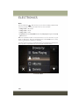
securely locked into position the seat will not provide the proper stability for child
seats and/or passengers. An improperly latched seat could cause serious injury.
HEATED STEERING WHEEL
The steering wheel contains a heating element that helps warm your hands in cold
weather. The heated steering wheel has only one temperature setting. Once the
heated steering wheel switch
has been turned on, it will operate for up to 80
minutes before automatically shutting off. The heated steering wheel can shut off
early or may not turn on when the steering wheel is already warm. The heated steering
wheel control button is located on the center of the instrument panel below the radio
screen.
32
GETTING STARTED
WARNING!
• Persons who are unable to feel pain to the skin because of advanced age,
chronic illness, diabetes, spinal cord injury, medication, alcohol use, exhaustion, or other physical conditions must exercise care when using the steering
wheel heater. It may cause burns even at low temperatures, especially if used
for long periods.
• Do not place anything on the steering wheel that insulates against heat, such
as a blanket or steering wheel covers of any type and material. This may cause
the steering wheel heater to overheat.
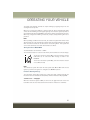
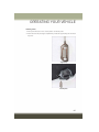
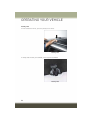
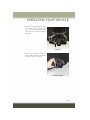
TILT/TELESCOPING STEERING COLUMN
This feature allows you to tilt the steering column upward or downward. It also allows
you to lengthen or shorten the steering column. The tilt/telescoping lever is located
below the steering wheel at the end of the steering column.
To unlock the steering column, push the
tilt/telescoping lever downward (toward
the floor). To tilt the steering column,
move the steering wheel upward or downward as desired. To lengthen or shorten
the steering column, pull the steering
wheel outward or push it inward as desired.
To lock the steering column in position,
pull the tilt/telescoping lever upward until fully engaged.
Tilt Steering Wheel Lever
WARNING!
Do not adjust the steering column while driving. Adjusting the steering column
while driving or driving with the steering column unlocked, could cause the driver
to lose control of the vehicle. Failure to follow this warning may result in serious
injury or death.
33
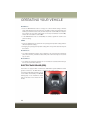
OPERATING YOUR VEHICLE
ENGINE BREAK-IN RECOMMENDATIONS
A long break-in period is not required for the engine and drivetrain (transmission and
axle) in your vehicle.
Drive moderately during the first 300 miles (500 km). After the initial 60 miles
(100 km), speeds up to 50 or 55 mph (80 or 90 km/h) are desirable.
While cruising, brief full-throttle acceleration within the limits of local traffic laws
contributes to a good break-in. Wide-open throttle acceleration in low gear can be
detrimental and should be avoided.
The engine oil installed in the engine at the factory is a high-quality energy
conserving type lubricant. Oil changes should be consistent with anticipated climate
conditions under which vehicle operations will occur. Refer to “Maintaining Your
Vehicle” for the recommended viscosity and quality grades.
NOTE:
A new engine may consume some oil during its first few thousand miles (kilometers)
of operation. This should be considered a normal part of the break-in and not
interpreted as an indication of an engine problem or malfunction.
CAUTION!
Never use Non-Detergent Oil or Straight Mineral Oil in the engine or damage may
result.
EXTERIOR LIGHTS
Headlights
The headlight switch is located on the left side of the instrument panel. The
headlight switch controls the operation of the headlights, side marker lights, daytime
running lights, fog lights and the dimming of the instrument cluster and interior
lighting.
Turning on the headlights will illuminate
the instrument cluster and the controls
located on the instrument panel.
Headlight Switch
34
OPERATING YOUR VEHICLE
Automatic Lighting — If Equipped
Light Sensor
The light sensor is equipped with an infrared LED, located on the windshield. It
detects changes in light intensity outside the vehicle, based on the sensitivity of light
set by using the Menu on the display or on the Uconnect® system.
The higher the sensitivity, the lesser the amount of external light required for
controlling the lighting.
Automatic Headlights
Turn the headlight switch to the AUTO position.
When the automatic headlights are enabled, the headlight time delay is active. After
the ignition switch is placed in the STOP/OFF position, the headlights will automatically turn off after approximately 90 seconds depending on the settings of the
feature.
The timing of the headlights is adjustable between 0, 30, 60 and 90 seconds.
NOTE:
The engine must be running before the headlights will come on in the automatic
mode.
Daytime Running Lights (DRL) — If Equipped
The Daytime Running Lights (DRLs) will turn on when the engine is started and
remain on unless the headlights are turned on, the electronic parking brake is
applied, or the engine is shut off.
The DRLs will be disabled during turn signal operation and resume operation when
the turn signal operation has ended.
Front Fog Lights — If Equipped
The front fog light switch is built into the headlight switch.
To activate the front fog lights, turn on the parking lights or the low beam headlights
and push the headlight switch. To turn off the front fog lights, push the headlight
switch a second time or turn off the headlight switch.
An indicator light in the instrument cluster illuminates when the fog lights are turned
on.
NOTE:
The fog lights will operate with the low beam headlights or parking lights on.
Selecting the high beam headlights will turn off the fog lights.
35
OPERATING YOUR VEHICLE
Parking Lights
Rotate the headlight switch to the first position to turn on the parking lights. The
parking light indicator in the cluster will illuminate.
Headlight Delay
This feature provides the safety of headlight illumination for up to 90 seconds when
leaving your vehicle in an unlit area.
The time delay of the headlights is programmable between 0, 30, 60 and 90
seconds.
Headlight Delay Activation
To activate the delay feature, place the ignition in the STOP/OFF position while the
headlights are still on. Then, turn off the headlights within two minutes. The delay
interval begins when the headlight switch is turned off.
Headlight Delay Disable
The feature is disabled by turning on the headlights, the parking lights or by placing
the ignition in the MAR/RUN position.
If you shut off the lights before the ignition is turned on, they will turn off in the
normal manner.
NOTE:
The lights must be turned off within two minutes of placing the ignition in the
STOP/OFF position to activate this feature.
Flash-To-Pass
You can signal another vehicle with your headlights by lightly pulling the multifunction lever toward you. This will cause the headlights to turn on at high beam and
remain on until the lever is released.
36
OPERATING YOUR VEHICLE
High Beams
To turn on the high beam headlights, push the turn signal lever forward (toward the
front of the vehicle) and an indicator will illuminate in the cluster. To turn off the high
beams, pull the turn signal lever rearward (toward the rear of the vehicle).
NOTE:
The headlights must be on for the high
beams to activate.
Turn Signals
Move the multifunction lever up or down
and the arrows on each side of the instrument cluster flash to show proper operation of the front and rear turn signal
lights.
High Beam And Turn Signal Controls
• A “Turn Signal On” message will appear in the instrument cluster and a
continuous chime will sound if the vehicle is driven more than 1 mile (1.6 km) with
either turn signal on.
• When the Daytime Running Lights are on and a turn signal is activated, the
Daytime Running Lamp will turn off on the side of the vehicle in which the turn
signal is flashing. The Daytime Running Lamp will turn back on when the turn
signal is turned off.
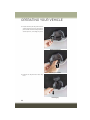
WIPERS AND WASHERS
The windshield wiper/washer controls are located on the lever on the right side of the
steering column. The front wipers are operated by rotating a switch, located on the
end of the lever.
CAUTION!
Always remove any buildup of snow that prevents the windshield wiper blades
from returning to the “park” position. If the windshield wiper switch is turned off,
and the blades cannot return to the “park” position, damage to the wiper motor
may occur.
Rear Wiper Operation
The rear wiper/washer controls are located on the lever on the right side of the
steering column. The rear wiper/washer is operated by rotating a switch, located at
the middle of the lever.
Rotate the center portion of the lever upward to the first detent for intermittent
operation and to the second detent for continuous rear wiper operation.
37
OPERATING YOUR VEHICLE
To use the washer, push the lever forward and hold while spray is desired. If the lever
is pushed while in the intermittent setting, the wiper will turn on and operate for
several wipe cycles after the end of the lever is released, and then resume the
intermittent interval previously selected.
If the lever is pushed while the wiper is in the off position, the wiper will operate for
several wipe cycles, then turn off.
NOTE:
As a protective measure, the pump will stop if the switch is held for more than 30
seconds. Once the lever is released, the pump will resume normal operation.
If the rear wiper is operating when the ignition is turned to the STOP/OFF position,
the wiper will automatically return to the “park” position.
Rear Window Defroster
The rear window defroster button is located with the Climate Controls on the
instrument panel. Push this button to turn on the rear window defroster. An indicator
in the button will illuminate when the rear window defroster is on. The rear window
defroster automatically turns off after approximately 20 minutes. To manually shut
the defroster off, push the button a second time.
CAUTION!
Failure to follow these cautions can cause damage to the heating elements:
• Use care when washing the inside of the rear window. Do not use abrasive
window cleaners on the interior surface of the window. Use a soft cloth and a
mild washing solution, wiping parallel to the heating elements. Labels can be
peeled off after soaking with warm water.
• Do not use scrapers, sharp instruments, or abrasive window cleaners on the
interior surface of the window.
• Keep all objects a safe distance from the window.
Windshield Wiper De-Icer — If Equipped
Your vehicle may be equipped with a Windshield Wiper De-Icer feature that may be
activated under the following conditions:
• Activation By Front Defrost — The Windshield Wiper De-Icer will be activated
automatically in the case of a cold weather manual start with full front defrost, and
the ambient temperature is below 40° F (4.4° C).
• Activation By Rear Defrost — The Windshield Wiper De-Icer will be activated
automatically when the rear defrost is turned on and the ambient temperature is
below 40° F (4.4° C).
• Activation By Remote Start Operation — When Remote Start is active and the
outside ambient temperature is less than 40° F (4.4° C), the Windshield Wiper
De-Icer will be enabled. Upon exiting remote start mode the Windshield Wiper
De-Icer will remain on.
38
OPERATING YOUR VEHICLE
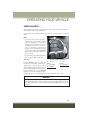
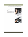
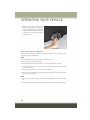
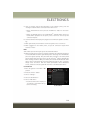
SPEED CONTROL
When engaged, the Electronic Speed Control takes over accelerator operations at
speeds greater than 25 mph (40 km/h).
The Electronic Speed Control buttons are located on the right side of the steering
wheel.
NOTE:
• In order to ensure proper operation,
the Electronic Speed Control System
has been designed to shut down if
multiple Speed Control functions are
operated at the same time. If this occurs, the Electronic Speed Control
System can be reactivated by pushing
the Electronic Speed Control ON/OFF
button and resetting the desired vehicle set speed.
• The Electronic Speed Control function
will not work in 4WD Low Range.
Electronic Speed Control Buttons
Activation
Push the ON/OFF button to activate the
Electronic Speed Control. The Cruise Indicator Light in the Electronic Vehicle
Information Center (EVIC) or Driver Information Display (DID) will illuminate. To
turn the system off, push the ON/OFF
button a second time. The Cruise Indicator Light will turn off. The system should
1 — SET+/
ACCEL
2 — RESUME
3 — ON/OFF
4 — SET-/
DECEL
5 — CANCEL
be turned off when not in use.
WARNING!
Leaving the Electronic Speed Control system on when not in use is dangerous. You
could accidentally set the system or cause it to go faster than you want. You could
lose control and have an accident. Always leave the system OFF when you are not
using it.
39
OPERATING YOUR VEHICLE
Setting A Desired Speed
Turn the Electronic Speed Control ON.
NOTE:
The vehicle should be traveling at a steady speed and on level ground before pushing
the SET (+) or SET (-) button.
When the vehicle has reached the desired speed, push the SET (+) or SET (-) button
and release. Release the accelerator and the vehicle will operate at the selected
speed.
Deactivation
A soft tap on the brake pedal, pushing the CANCEL button, or normal brake pressure
while slowing the vehicle will deactivate the Electronic Speed Control without erasing
the set speed from memory.
Pushing the ON/OFF button or turning the ignition switch OFF erases the set speed
from memory.
Resume Speed
To resume a previously set speed, push the RES button and release. Resume can be
used at any speed above 20 mph (32 km/h).
Varying The Speed
To Increase Speed
When the Electronic Speed Control is set, you can increase speed by pushing the SET
+ button.
The drivers preferred units can be selected through the Uconnect® system if
equipped. The speed increment shown is dependant on the chosen speed unit of
U.S. (mph) or Metric (km/h):
U.S. Speed (mph)
• Pushing the SET + button once will result in a 1 mph increase in set speed. Each
subsequent tap of the button results in an increase of 1 mph.
• If the button is continually pushed, the set speed will continue to increase until
the button is released, then the new set speed will be established.
Metric Speed (km/h)
• Pushing the SET + button once will result in a 1 km/h increase in set speed. Each
subsequent tap of the button results in an increase of 1 km/h.
• If the button is continually pushed, the set speed will continue to increase until
the button is released, then the new set speed will be established.
40
OPERATING YOUR VEHICLE
To Decrease Speed
When the Electronic Speed Control is set, you can decrease speed by pushing the
SET - button.
The drivers preferred units can be selected through the Uconnect® system if
equipped. The speed increment shown is dependant on the chosen speed unit of
U.S. (mph) or Metric (km/h):
U.S. Speed (mph)
• Pushing the SET - button once will result in a 1 mph decrease in set speed. Each
subsequent tap of the button results in a decrease of 1 mph.
• If the button is continually pushed, the set speed will continue to decrease until
the button is released, then the new set speed will be established.
Metric Speed (km/h)
• Pushing the SET - button once will result in a 1 km/h decrease in set speed. Each
subsequent tap of the button results in a decrease of 1 km/h.
• If the button is continually pushed, the set speed will continue to decrease until
the button is released, then the new set speed will be established.
Accelerating For Passing
Push the accelerator as you would normally. When the pedal is released, the vehicle
will return to the set speed.
41
OPERATING YOUR VEHICLE
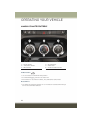
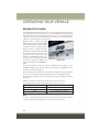
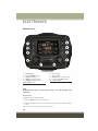
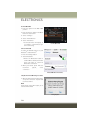
MANUAL CLIMATE CONTROLS
Manual Climate Controls
1 — Blower Control
2 — Temperature Control
3 — Mode Control
4 — Rear Defroster
5 — A/C Control
6 — Air Recirculation Control
Air Recirculation
• Use recirculation for maximum A/C operation.
• For window defogging, turn the recirculation off.
• Recirculation is not allowed in defrost, floor, defrost/floor (mix) modes.
Heated Mirrors
• The mirrors are heated to melt frost or ice. This feature is activated whenever you
turn on the rear window defroster.
42
OPERATING YOUR VEHICLE
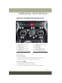
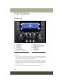
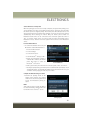
AUTOMATIC TEMPERATURE CONTROLS (ATC)
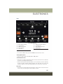
Automatic Temperature Controls (ATC)
1
2
3
4
5
6
7
—
—
—
—
—
—
—
Driver Temperature Control
A/C Control
MAX Front Defrost Control
Blower Control
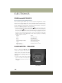
LED Blower Speed Indicator
AUTO Control
Passenger Temperature Control
8 — Passenger Temperature Display
9 — SYNC Control
10 — Rear Defroster
11 — Mode Control
12 — Climate On/Off Control
13 — Air Recirculation Control
14 — Driver Temperature Display
Automatic Operation
• Push the AUTO button.
• Select the desired temperature by rotating temperature control knobs.
• The system will maintain the set temperature automatically.
Air Recirculation
• Use Recirculation for maximum A/C operation.
• For window defogging, turn the recirculation off.
• Recirculation is not allowed in defrost, floor, defrost/floor (mix) modes.
43
OPERATING YOUR VEHICLE
Max Defrost
• Push the MAX Defrost button to change the current airflow setting to Defrost
mode. Performing this function will cause the ATC to change to manual mode, the
blower speed will increase to full, the A/C compressor is turned ON, the temperature controls are set to (HI), defrost mode is selected, rear defroster is turned ON,
and the air recirculation is turned OFF.
• If the MAX Defrost mode is turned OFF, the climate system will return to the
previous setting.
SYNC
• Push the SYNC button to synchronize the passenger temperature setting with the
driver temperature setting.
• Changing the passenger temperature setting while in Sync will automatically exit
this feature.
Mode Buttons
• The airflow distribution modes can be adjusted so air comes from the instrument
panel, floor, de-mist, and defrost outlets. One, two or all modes may be selected at
any one time.
Heated Mirrors
• The mirrors are heated to melt frost or ice. This feature is activated whenever you
turn on the rear window defroster.
ELECTRIC PARK BRAKE (EPB)
Your vehicle is equipped with a new Electric Park Brake System (EPB) that offers
greater convenience. The EPB switch is located in the center console.
To apply the park brake manually, pull up
on the switch momentarily. The BRAKE
warning lamp in the instrument cluster
and an indicator on the switch will illuminate.
Park Brake Switch
44
OPERATING YOUR VEHICLE
To release the park brake manually, the ignition switch must be in RUN. Then put
your foot on the brake pedal and push the park brake switch down momentarily. Once
the park brake is fully disengaged, the BRAKE warning lamp and the switch indicator
will extinguish.
The park brake can also be automatically released. With the engine running and the
transmission in gear, release the brake pedal and depress the throttle pedal. For
safety reasons, your seat belt must also be fastened.
NOTE:
• You may hear a slight whirring sound from the back of the vehicle while the
parking brake engages or disengages.
• If your foot is on the brake pedal while you are engaging or disengaging the parking
brake, you may notice a small amount of brake pedal movement.
• The new Auto Park Brake feature can be used to apply the park brake automatically every time you park the vehicle. Auto Park Brake can be enabled and disabled
in the Settings menu in Uconnect® or in “Safe Hold” conditions.
• The parking brake can be engaged even when the ignition switch is OFF, however,
it can only be disengaged when the ignition switch is in the ON/RUN position.
• Safehold is a new feature that will automatically apply the park brake under
certain conditions. The EPB monitors the status of the driver’s seat belt, driver’s
door and pedal positions to determine if the driver may have exited while the
vehicle is still capable of moving and will then automatically apply the park brake
to prevent the vehicle from rolling.
• The EPB fault lamp will illuminate if the EPB switch is held for longer than 20
seconds in either the released or applied position. The light will extinguish upon
releasing the switch.
• Refer to the Starting and Operating section of your vehicle’s Owner’s Manual on
the DVD for further details.
CAUTION!
If the Brake System Warning Light remains on with the parking brake released, a
brake system malfunction is indicated. Have the brake system serviced by an
authorized dealer immediately.
45
OPERATING YOUR VEHICLE
WARNING!
• Never use the PARK position as a substitute for the parking brake. Always apply
the parking brake fully when parked to guard against vehicle movement and
possible injury or damage.
• When leaving the vehicle, always remove the key fob from the ignition and lock
your vehicle. If equipped with Keyless Enter-N-Go, always make sure the
keyless ignition node is in “OFF” mode, remove the Key Fob from the vehicle
and lock the vehicle
• Never leave children alone in a vehicle, or with access to an unlocked vehicle.
Allowing children to be in a vehicle unattended is dangerous for a number of
reasons. A child or others could be seriously or fatally injured. Children should
be warned not to touch the parking brake, brake pedal or the transmission gear
selector.
• Do not leave the Key Fob in or near the vehicle (or in a location accessible to
children), and do not leave the ignition of a vehicle equipped with Keyless
Enter-N-Go™ in the ON/RUN mode. A child could operate power windows,
other controls, or move the vehicle.
• Be sure the parking brake is fully disengaged before driving; failure to do so can
lead to brake failure and a collision.
• Always fully apply the parking brake when leaving your vehicle, or it may roll
and cause damage or injury. Also be certain to leave the transmission in PARK.
Failure to do so may allow the vehicle to roll and cause damage or injury.
BLIND SPOT MONITORING (BSM)
The Blind Spot Monitoring (BSM) system uses two radar-based sensors, located
inside the rear bumper fascia, to detect highway licensable vehicles (automobiles,
trucks, motorcycles, etc.) that enter the blind spot zones from the rear/front/side of
the vehicle.
When the vehicle is started, the BSM warning light will momentarily illuminate in
both outside rear view mirrors to let the driver know that the system is operational.
The BSM system sensors operate when the vehicle is in any forward gear or REVERSE
and enters stand-by mode when the vehicle is in PARK.
46
OPERATING YOUR VEHICLE
The BSM detection zone covers approximately one lane width on both sides of the
vehicle, 10 ft (3 m). The zone length starts at the outside mirror and extends
approximately 20 ft (6 m) beyond the rear bumper of the vehicle. The BSM system
monitors the detection zones on both sides of the vehicle when the vehicle speed
reaches approximately 6 mph (10 km/h) or higher and will alert the driver of vehicles
in these areas.
NOTE:
• The BSM system does NOT alert the driver about rapidly approaching vehicles that
are outside the detection zones.
• If a trailer is connected to the vehicle, it is necessary to deactivate BSM system
manually by settings menu to avoid a miss-detection. Refer to “Uconnect® Settings” in
“Multimedia” in your Owner’s Manual on the DVD for further information.
The area on the rear fascia where the radar sensors are located must remain free of
snow, ice, and dirt/road contamination so that the BSM system can function properly.
Do not block the radar sensors located on the rear fascia with foreign objects (bumper
stickers, bicycle racks, etc.).
The BSM system notifies the driver of objects in the detection zones by illuminating
the BSM warning light located in the outside mirrors in addition to sounding an
audible (chime) alert and reducing the radio volume.
The BSM system monitors the detection zone from three different entry points (side,
rear, front) while driving to see if an alert is necessary. The BSM system will issue an
alert during these types of zone entries.
Entering From The Side
Vehicles that move into your adjacent lanes from either side of the vehicle.
Entering From The Rear
Vehicles that come up from behind your vehicle on either side and enter the rear
detection zone with a relative speed of less than 31 mph (50 km/h).
Overtaking Traffic
If you pass another vehicle slowly with a relative speed less than 15 mph (25 km/h)
and the vehicle remains in the blind spot for approximately 1.5 seconds, the warning
light will be illuminated. If the difference in speed between the two vehicles is
greater than 15 mph (25 km/h), the warning light will not illuminate.
The BSM system is designed not to issue an alert on stationary objects such as
guardrails, posts, walls, foliage, berms, etc. However, occasionally the system may
alert on such objects. This is normal operation and your vehicle does not require
service.
The BSM system will not alert you of objects that are traveling in the opposite
direction of the vehicle in adjacent lanes.
47
OPERATING YOUR VEHICLE
WARNING!
The Blind Spot Monitoring system is only an aid to help detect objects in the blind
spot zones. The BSM system is not designed to detect pedestrians, bicyclists, or
animals. Even if your vehicle is equipped with the BSM system, always check your
vehicles mirrors, glance over your shoulder, and use your turn signal before
changing lanes. Failure to do so can result in serious injury or death.
Rear Cross Path (RCP)
The Rear Cross Path (RCP) feature is intended to aid the driver when backing out of
parking spaces where their vision of oncoming vehicles may be blocked. Proceed
slowly and cautiously out of the parking space until the rear end of the vehicle is
exposed. The RCP system will then have a clear view of the cross traffic and if an
oncoming vehicle is detected, alert the driver.
RCP monitors the rear detection zones on both sides of the vehicle, for objects that
are moving toward the side of the vehicle with a minimum speed of approximately
1 mph (2 km/h), to objects moving a maximum of approximately 22 mph (35 km/h),
such as in parking lot situations.
NOTE:
In a parking lot situation, oncoming vehicles can be obscured by vehicles parked on
either side. If the sensors are blocked by other structures or vehicles, the system will
not be able to alert the driver.
When RCP is on and the vehicle is in REVERSE, the driver is alerted using both the
visual and audible alarms, including reducing the radio volume.
WARNING!
RCP is not a Back Up Aid system. It is intended to be used to help a driver detect
an oncoming vehicle in a parking lot situation. Drivers must be careful when
backing up, even when using RCP. Always check carefully behind your vehicle,
look behind you, and be sure to check for pedestrians, animals, other vehicles,
obstructions, and blind spots before backing up. Failure to do so can result in
serious injury or death.
Mode Of Operation
Three selectable modes of operation are available in the Uconnect® System. Refer to
“Uconnect® Settings” in “Multimedia” in your Owner’s Manual on the DVD for
further information.
48
OPERATING YOUR VEHICLE
Blind Spot Alert Lights Only
When operating in Blind Spot Alert mode, the BSM system will provide a visual alert
in the appropriate side view mirror based on a detected object. However, when the
system is operating in Rear Cross Path (RCP) mode, the system will respond with
both visual and audible alerts when a detected object is present. Whenever an
audible alert is requested, the radio is muted.
Blind Spot Alert Lights/Chime
When operating in Blind Spot Alert Lights/Chime mode, the BSM system will provide
a visual alert in the appropriate side view mirror based on a detected object. If the
turn signal is then activated, and it corresponds to an alert present on that side of the
vehicle, an audible chime will also be sounded. Whenever a turn signal and detected
object are present on the same side at the same time, both the visual and audible
alerts will be issued. In addition to the audible alert, the radio (if on) will also be
muted.
NOTE:
Whenever an audible alert is requested by the BSM system, the radio is also muted.
When the system is in RCP, the system will respond with both visual and audible
alerts when a detected object is present. Whenever an audible alert is requested, the
radio is also muted. Turn/hazard signal status is ignored; the RCP state always
requests the chime.
Blind Spot Alert Off
When the BSM system is turned off, there will be no visual or audible alerts from
either the BSM or RCP systems.
NOTE:
The BSM system will store the current operating mode when the vehicle is shut off.
Each time the vehicle is started the previously stored mode will be recalled and used.
Blind Spot Monitoring Fault Warnings
Sensor Blinded
In the case of a sensor blinded:
• BSM Mirror Warning Lights are turned on continuously.
• A chime will turn on.
• A instrument cluster message will display “Blind Spot Monitoring Unavailable - Wipe
Rear Bumper Corners.”
NOTE:
The rear bumper must be clean and free of any obstructing debris.
49
OPERATING YOUR VEHICLE
System Not Available
In the case of the system being temporary unavailable:
• BSM Mirror Warning Lights are turned on continuously.
• A chime will turn on.
• A instrument cluster message will display “Blind Spot Monitoring Temporary
Unavailable.”
In the case of the system being completely unavailable:
• A chime will turn on.
• A instrument cluster message will display “Blind Spot Monitoring Unavailable Service Required.”
NOTE:
Vehicle must be taken to the nearest authorized dealer for service.
FORWARD COLLISION WARNING (FCW) WITH
MITIGATION
Forward Collision Warning (FCW) With Mitigation Operation — If Equipped
The Forward Collision Warning (FCW) system with mitigation provides the driver with
audible warnings, visual warnings (within the EVIC/DID), and may apply a brake jerk
to warn the driver when it detects a potential frontal collision. The warnings and
limited braking are intended to provide the driver with enough time to react, avoid or
mitigate the potential collision.
NOTE:
• FCW monitors the information from the forward looking sensors as well as the
Electronic Brake Controller (EBC), to calculate the probability of a forward
collision. When the system determines that a forward collision is probable, the
driver will be provided with audible and visual warnings and may provide a brake
jerk warning.
• If the driver does not take action based upon these progressive warnings, then the
system will provide a limited level of active braking to help slow the vehicle and
mitigate the potential forward collision. If the driver reacts to the warnings by
braking and the system determines that the driver intends to avoid the collision by
braking but has not applied sufficient brake force, the system will compensate and
provide additional brake force as required.
Vehicles With A Manual Transmission: After the end of the intervention of automatic
braking, the engine could stall, unless the driver can depress the clutch pedal.
50
OPERATING YOUR VEHICLE
Vehicles With Automatic Transmission: After the end of the intervention of automatic
braking, the transmission may remain in last gear stored: therefore the car could
lurch forward, once the brakes release a few seconds later. If the Forward Collision
Warning with Mitigation event stops the vehicle completely, the system will hold the
vehicle at standstill for two seconds and then release the brakes.
If a Forward Collision Warning with Mitigation event begins at a speed below 20 mph
(32 km/h), the system may provide the maximum braking possible to mitigate the
potential forward collision. If the Forward Collision Warning with Mitigation event
stops the vehicle completely, the system will hold the vehicle at standstill for two
seconds and then release the brakes.
When the system determines a collision with the vehicle in front of you is no longer
probable, the warning message will be deactivated.
NOTE:
• The minimum speed for FCW activation is 4 mph (7 km/h).
• The maximum speed for FCW activation is 124 mph (200 km/h).
• The FCW alerts may be triggered on objects other than vehicles such as guard rails
or sign posts based on the course prediction. This is expected and is a part of
normal FCW activation and functionality.
• The FCW system is intended for on-road use only. If the vehicle is taken off-road,
the FCW system should be deactivated to prevent unnecessary warnings to the
surroundings.
• If the vehicle enters 4WD Low Range, the FCW system will be automatically
deactivated.
• The system is active only if the front seat belts are fastened.
WARNING!
Forward Collision Warning (FCW) is not intended to avoid a collision on its own, nor
can FCW detect every type of potential collision. The driver has the responsibility
to avoid a collision by controlling the vehicle via braking and steering. Failure to
follow this warning could lead to serious injury or death.
51
OPERATING YOUR VEHICLE
Turning FCW ON And OFF
The forward collision menu setting is located in the Uconnect® settings.
NOTE:
The default status of FCW is “Warning + Active Braking,” this allows the system to
warn you of a possible collision with the vehicle in front of you and enable the active
braking.
• Changing the FCW status to “Off” deactivates the system, so no warning or active
braking will be available in case of a possible collision
• Changing the FCW status to “Only warning” prevents the system from providing
limited active braking, or additional brake support if the driver is not braking
adequately in the event of a potential frontal collision, but maintains the audible
and visual warnings.
Changing the status of the system is only possible with the vehicle at a complete
stop.
NOTE:
The FCW system state is not kept in memory from one key cycle to the next. If the
system is turned OFF, it will turn On when the vehicle is restarted.
Changing FCW Sensitivity
By changing the settings on the menu of the Uconnect® system, you can change the
sensitivity of the system by choosing one of the following three options: "Near",
"Medium" or "Far".
The default option is "Medium". This setting provides that the system notify the driver
of a possible accident with the vehicle ahead of it when the latter is at a standard
distance, intermediate between the other two possible settings.
By setting the sensitivity of the system to "Far", the system will warn the driver of a
possible accident with the vehicle in front when the latter is at a greater distance,
giving you the chance to act on the brakes in a more limited and gradual. This setting
gives the driver the maximum possible time of reaction to prevent a possible
accident.
By changing the option to "Near", the system will warn the driver of a possible
accident with the vehicle ahead of it when the latter is a reduced distance. This
setting offers a reaction time to the driver lower than the settings "Medium" and "Far",
in the case of a potential accident, while a more dynamic driving of the car.
The setting of the sensitivity of the system is maintained in memory when the engine
is switched off.
52
OPERATING YOUR VEHICLE
FCW Limited Warning
If the EVIC/DID displays “FCW Limited Functionality” or “FCW Limited Functionality
Clean Front Windshield” momentarily, there may be a condition that limits FCW
functionality. Although the vehicle is still drivable under normal conditions, the
active braking may not be fully available. Once the condition that limited the system
performance is no longer present, the system will return to its full performance state.
If the problem persists, see your authorized dealer.
Service FCW Warning
If the system turns off, and the EVIC/DID displays:
• FCW Unavailable Service Required
This indicates there is an internal system fault. Although the vehicle is still drivable
under normal conditions, have the system checked by an authorized dealer.
“Wipe Front Radar Sensor In Front Of Vehicle” Warning
The “FCW Front Radar Sensor Temporarily Blocked” warning will display when
conditions temporarily limit system performance. This most often occurs at times of
poor visibility, such as in snow or heavy rain. The system may also become
temporarily blinded due to obstructions, such as mud, dirt or ice. In these cases, the
EVIC/DID will display “ FCW Front Radar Sensor Temporarily Blocked” and the
system will deactivate.
The “FCW Front Radar Sensor Temporarily Blocked” message can sometimes be
displayed while driving in highly reflective areas (i.e. tunnels with reflective tiles, or
ice and snow). The system will recover after the vehicle has left these areas. Under
rare conditions, when the radar is not tracking any vehicles or objects in its path this
warning may temporarily occur.
If weather conditions are not a factor, the driver should examine the sensor. It may
require cleaning or removal of an obstruction. The sensor is located behind the lower
grille. In absence of visible obstructions on the bumper, it could be necessary to wipe
off the radar directly on the surface, after having the radar cover removed. It’s
recommended that your authorized dealer perform’s this operation.
NOTE:
• If the “FCW Front Radar Sensor Temporarily Blocked” message occurs frequently
(e.g. more than once on every trip) without any snow, rain, mud, or other
obstruction, have the radar sensor realigned at your authorized dealer.
• Installing a snow plow, front-end protector, an aftermarket grille or modifying the
grille is not recommended. Doing so may block the sensor and inhibit FCW
operation.
53
OPERATING YOUR VEHICLE
Precautions While Driving With FCW
In certain driving conditions, such as:
• Driving in the vicinity of a curve
• Small vehicles and/or not aligned to the lane
• Lane changing of other vehicles
• Passing of vehicles in an oncoming intersection
The intervention of the system could be unexpected or delayed. The driver must
therefore always pay particular attention, while maintaining control of the car to drive
in complete safety.
Driving In The Vicinity Of A Curve
Entering or exiting a large curve, the system could detect the presence of a vehicle
that is in front of the car, but that does not preside in the same lane. In cases such
as this, the system might respond.
Small Vehicles And/Or Not Aligned To The Lane
The system is not able to detect the presence of vehicles that are in front of the car
but placed outside the field of action of the radar sensor and could therefore not react
in the presence of small vehicles such as bicycles or motorcycles.
Lane Changing Of Other Vehicles
Vehicles that suddenly change lane, while standing in the traffic lane of their car and
inside the field of action of the radar sensor may cause the intervention of the system.
Passing Of Vehicles In An Oncoming Intersection
The system could temporarily react to a vehicle that crossed the range of the radar
sensor, in an oncoming intersection.
LANESENSE
LaneSense Operation
The LaneSense system is operational at speeds above 37 mph (60 km/h) and below
112 mph (180 km/h). The LaneSense system uses a forward looking camera to
detect lane markings and measure vehicle position within the lane boundaries.
When both lane markings are detected and the driver unintentionally drifts out of the
lane (no turn signal applied), the LaneSense system provides a haptic warning in the
form of torque applied to the steering wheel to prompt the driver to remain within the
lane boundaries. If the driver continues to unintentionally drift out of the lane, the
LaneSense system provides a visual warning through the Electronic Vehicle Information Center (EVIC) or Driver Information Display (DID) to prompt the driver to remain
within the lane boundaries.
54
OPERATING YOUR VEHICLE
The driver may manually override the haptic warning by applying torque into the
steering wheel at any time.
When only a single lane marking is detected and the driver unintentionally drifts
across the lane marking (no turn signal applied), the LaneSense system provides a
visual warning through the EVIC/DID to prompt the driver to remain within the lane.
When only a single lane marking is detected, a haptic (torque) warning will not be
provided.
NOTE:
When operating conditions have been met, the LaneSense system will monitor if the
driver’s hands are on the steering wheel and provides an audible warning to the driver
when the driver’s hands are not detected on the steering wheel. The system will
cancel if the driver does not return their hands to the wheel.
Turning LaneSense ON Or OFF
The default status of LaneSense is “OFF”.
The LaneSense button is located on the switch panel below the Uconnect® display.
To turn the LaneSense system ON, push the LaneSense button
(LED turns on). A “Lane Sense On” message is shown in the
EVIC/DID.
To turn the LaneSense system OFF, push the LaneSense button
once (LED turns off).
NOTE:
The LaneSense system will retain the last system state ON or OFF from the last
ignition cycle when the ignition is changed to the ON/RUN position.
LaneSense Warning Message
The LaneSense system will indicate the current lane drift condition through the
Electronic Vehicle Information Center (EVIC) or Driver Information Display (DID).
3.5 EVIC Screen — If Equipped
When the LaneSense system is ON, the lane lines are gray when both of the lane
boundaries have not been detected and the LaneSense indicator is solid white.
55
OPERATING YOUR VEHICLE
Left Lane Departure — Only Left Lane Detected
• When the LaneSense system is ON, the LaneSense indicator is solid white when
only the left lane marking has been detected and the system is ready to provide
visual warnings in the EVIC if an unintentional lane departure occurs.
• When the LaneSense system senses the lane has been approached and is in a lane
departure situation, the left thick lane line flashes from white to gray, the left thin
line remains solid white and the LaneSense indicator changes from solid white to
flashing yellow.
NOTE:
The LaneSense system operates with the similar behavior for a right lane departure
when only the right lane marking has been detected.
Left Lane Departure — Both Lanes Detected
• When the LaneSense system is ON, the lane lines turn from gray to white to
indicate that both of the lane markings have been detected. The LaneSense
indicator is solid green when both lane markings have been detected and the
system is “armed” to provide visual warnings in the EVIC and a torque warning in
the steering wheel if an unintentional lane departure occurs.
• When the LaneSense system senses a lane drift situation, the left thick lane line
and the left thin line turn solid white. The LaneSense indicator changes from solid
green to solid yellow. At this time torque is applied to the steering wheel in the
opposite direction of the lane boundary.
For example: If approaching the left side of the lane, the steering wheel will turn to
the right.
• When the LaneSense system senses the lane has been approached and is in a lane
departure situation, the left thick lane line flashes from white to gray, the left thin
line remains solid white and the LaneSense indicator changes from solid yellow to
flashing yellow. At this time, torque is applied to the steering wheel in the opposite
direction of the lane boundary.
For example: If approaching the left side of the lane, the steering wheel will turn to
the right.
NOTE:
The LaneSense system operates with the similar behavior for a right lane departure.
7.0 DID Screen — If Equipped
When the LaneSense system is ON, the lane lines are gray when both of the lane
boundaries have not been detected and the LaneSense indicator is solid white.
56
OPERATING YOUR VEHICLE
Left Lane Departure — Only Left Lane Detected
• When the LaneSense system is ON, the LaneSense indicator is solid white when
only the left lane marking has been detected and the system is ready to provide
visual warnings in the DID if an unintentional lane departure occurs.
• When the LaneSense system senses the lane has been approached and is in a lane
departure situation, the left thick lane line flashes yellow (on/off), the left thin line
remains solid yellow and the LaneSense indicator changes from solid white to
flashing yellow.
NOTE:
The LaneSense system operates with the similar behavior for a right lane departure
when only the right lane marking has been detected.
Left Lane Departure — Both Lanes Detected
• When the LaneSense system is ON, the lane lines turn from gray to white to
indicate that both of the lane markings have been detected. The LaneSense
indicator is solid green when both lane markings have been detected and the
system is “armed” to provide visual warnings in the DID and a torque warning in
the steering wheel if an unintentional lane departure occurs.
• When the LaneSense system senses a lane drift situation, the left thick lane line
and left thin line turn solid yellow. The LaneSense indicator changes from solid
green to solid yellow. At this time torque is applied to the steering wheel in the
opposite direction of the lane boundary.
For example: If approaching the left side of the lane the steering wheel will turn to the
right.
• When the LaneSense system senses the lane has been approached and is in a lane
departure situation, the left thick lane line flashes yellow (on/off) and the left thin
line remains solid yellow. The LaneSense indicator changes from solid yellow to
flashing yellow. At this time torque is applied to the steering wheel in the opposite
direction of the lane boundary.
For example: If approaching the left side of the lane the steering wheel will turn to the
right.
NOTE:
The LaneSense system operates with the similar behavior for a right lane departure.
57
OPERATING YOUR VEHICLE
Changing LaneSense Status
The LaneSense system has settings to adjust the intensity of the torque warning and
the warning zone sensitivity (early/late) that you can configure through the
Uconnect® system screen.
NOTE:
• When enabled the system operates above 37 mph (60 km/h) and below 112 mph
(180 km/h).
• Use of the turn signal suppresses the warnings.
• The system will not apply torque to the steering wheel whenever a safety system
engages. (anti-lock brakes, traction control system, electronic stability control,
forward collision warning, etc.).
REAR PARK ASSIST
The Rear Park Assist system provides visual and audible indications of the distance
between the rear fascia and a detected obstacle when backing up, e.g. during a
parking maneuver.
Rear Park Assist will retain the last system state (enabled or disabled) from the last
ignition cycle when the ignition is changed to the MAR/RUN position.
Rear Park Assist can be active only when the shift lever is in REVERSE.
Rear Park Assist Sensors
The four Rear Park Assist sensors, located in the rear fascia/bumper, monitor the area
behind the vehicle that is within the sensors’ field of view. The sensors can detect
obstacles from approximately 12 in (30 cm) up to 59 in (150 cm) from the rear
fascia/bumper in the horizontal direction, depending on the location, type and
orientation of the obstacle.
Chime
By shifting the vehicle in REVERSE and in the case of the presence of a rear obstacle,
an acoustic signal that varies with the distance of the obstacle from the bumper is
activated.
The frequency of the acoustic signal:
• Increases with the distance between car and object decreases.
• Becomes continuous when the distance that separates the car from the obstacle
is less than approximately 12 inches (30 cm), while terminates immediately if the
distance to the obstacle increases.
• Remains constant if the distance between car and obstacle remains unchanged.
If this situation occurs for the side sensors, the signal is stopped after approximately three seconds to avoid, for example, it activates in case of maneuver along
a wall.
58
OPERATING YOUR VEHICLE
When the system emits a beeping sound, the volume of the Uconnect® system, if
turned on, is automatically lowered by Rear Park Assist.
Detection Distances
If the sensors detect more obstacles, it is taken into account only what is the shorter
distance.
Instrument Cluster Display
Rear Park Assist is displayed on the instrument cluster only if you have selected the
item "beep and display" inside the "Settings" menu of the Uconnect® system.
If an obstacle is detected in the center rear region, the display will show a single solid
arc in the center rear region and will produce a one-half second tone. As the vehicle
moves closer to the obstacle, the display will show the single arc moving closer to the
vehicle and the sound tone will change from slow, to fast, to continuous.
If an obstacle is detected in the left and/or right rear region, the display will show a
single flashing arc in the left and/or right rear region and will produce a fast sound
tone. As the vehicle moves closer to the obstacle, the display will show the single arc
moving closer to the vehicle and the tone will change from fast to continuous.
In general, the car is closest to the obstacle when the display shows only a flashing
arc and the chime becomes continuous.
The color on the display depends on the distance and location of the obstacle.
Enabling And Disabling Rear Park Assist
Rear Park Assist can be enabled and disabled with the Rear Park Assist switch.
When the Rear Park Assist switch is pressed to disable the system, the instrument
cluster will display the “PARK ASSIST OFF” message for approximately five seconds.
Refer to “Electronic Vehicle Information Center (EVIC)” or “Driver Information
Display (DID)” in “Getting To Know Your Instrument Panel” in your owner’s manual
on the DVD for further information. When the shift lever is moved to REVERSE and
the system is disabled, the EVIC/DID will display the “PARK ASSIST OFF” message
for as long as the vehicle is in REVERSE.
The Rear Park Assist switch LED will be ON when Rear Park Assist is disabled or
requires service. The Rear Park Assist switch LED will be OFF when the system is
enabled. If the Rear Park Assist switch is pushed, and requires service, the Rear Park
Assist switch LED will blink momentarily, and then the LED will be ON.
Rear Park Assist will remember the previous state when the vehicle is switch off.
CAUTION!
After turning off the ignition, the ParkSense® remains in this setting until the next
key cycle, even in the case of changing the setting of starting MAR/RUN to
STOP/OFF and then again in MAR/RUN.
59
OPERATING YOUR VEHICLE
Service The Rear Park Assist System
During vehicle start up, when the Rear Park Assist System has detected a faulted
condition, the instrument cluster will actuate a single chime, once per ignition cycle,
and it will display the “PARK ASSIST UNAVAILABLE WIPE REAR SENSORS” or the
“PARK ASSIST UNAVAILABLE SERVICE REQUIRED” message. Refer to “Electronic
Vehicle Information Center (EVIC) or Driver Information Display (DID)” in your
owner’s manual on the DVD for further information. When the shift lever is moved to
REVERSE and the system has detected a faulted condition, the EVIC/DID will display
the "PARK ASSIST UNAVAILABLE WIPE REAR SENSORS" or "PARK ASSIST
UNAVAILABLE SERVICE REQUIRED" message for as long as the vehicle is in
REVERSE. Under this condition, Rear Park Assist will not operate.
If “PARK ASSIST UNAVAILABLE WIPE REAR SENSORS” appears in the Electronic
Vehicle Information Center (EVIC) or Driver Information Display (DID) make sure the
outer surface and the underside of the rear fascia/bumper is clean and clear of snow,
ice, mud, dirt or other obstructions and then cycle the ignition. If the message
continues to appear, see an authorized dealer.
If “PARK ASSIST UNAVAILABLE SERVICE REQUIRED” appears in the EVIC/DID,
see an authorized dealer.
Park Assist System Usage Precautions
NOTE:
• Ensure that the outer surface and the underside of the rear bumper is clean and
clear of snow, ice, mud, dirt or other obstruction to keep the Rear Park Assist
system operating properly.
• Jackhammers, large trucks, and other vibrations could affect the performance of
Rear Park Assist.
• Clean the Rear Park Assist sensors regularly, taking care not to scratch or damage
them. The sensors must not be covered with ice, snow, slush, mud, dirt or debris.
Failure to do so can result in the system not working properly. The Rear Park Assist
system might not detect an obstacle behind the fascia/bumper, or it could provide
a false indication that an obstacle is behind the fascia/bumper.
• Objects such as bicycle carriers, etc., must not be placed within 12 inches (30
cm) from the rear fascia/bumper while driving the vehicle. Failure to do so can
result in the system misinterpreting a close object as a sensor problem, causing a
failure indication to be displayed in the instrument cluster.
60
OPERATING YOUR VEHICLE
CAUTION!
• Rear Park Assist is only a parking aid and it is unable to recognize every
obstacle, including small obstacles. Parking curbs might be temporarily
detected or not detected at all. Obstacles located above or below the sensors
will not be detected when they are in close proximity.
• The vehicle must be driven slowly when using Rear Park Assist in order to be
able to stop in time when an obstacle is detected. It is recommended that the
driver looks over his/her shoulder when using Rear Park Assist.
WARNING!
• Drivers must be careful when backing up even when using the Rear Park Assist
system. Always check carefully behind your vehicle, look behind you, and be
sure to check for pedestrians, animals, other vehicles, obstructions, and blind
spots before backing up. You are responsible for safety and must continue to
pay attention to your surroundings. Failure to do so can result in serious injury
or death.
• Before using the Rear Park Assist System, it is strongly recommended that the
ball mount and hitch ball assembly is disconnected from the vehicle when the
vehicle is not used for towing. Failure to do so can result in injury or damage to
vehicles or obstacles because the hitch ball will be much closer to the obstacle
than the rear fascia when the warning display turns on the single flashing arc
and sounds the continuous tone. Also, the sensors could detect the ball mount
and hitch ball assembly, depending on its size and shape, giving a false
indication that an obstacle is behind the vehicle.
If it’s necessary to keep the trailer hitch and hitch ball assembly mounted for a long
period, it is possible to filter out the trailer hitch and hitch ball assembly presence in
sensor field of view. The filtering operation must be performed only by an authorized
dealer.
61
OPERATING YOUR VEHICLE
REAR BACK UP CAMERA
The Rear Back Up Camera that allows you to see an on-screen image of your vehicle's
rear surroundings when the shift lever is put into REVERSE. The image will be
displayed on the touchscreen display along with a note to “check entire surroundings” across the top of the screen. After five seconds this note will disappear. The
camera is located above the rear license plate.
When the vehicle is shifted out of REVERSE (with camera delay turned OFF),
the rear camera mode is exited and the
navigation or audio screen appears again.
When the vehicle is shifted out of REVERSE (with camera delay turned ON),
the camera image will continue to be
displayed for up to 10 seconds after
shifting out of REVERSE unless the vehicle speed exceeds 8 mph (13 km/h),
the vehicle is shifted into PARK or the
ignition is switched to the STOP/OFF position.
Parking Camera
A touchscreen button to disable the camera is available when the vehicle is not in
REVERSE. Display of the camera image after shifting out of REVERSE can be
disabled via Uconnect® Settings.
When enabled, active guide lines are overlaid on the image to illustrate the width of
the vehicle and its projected backup path based on the steering wheel position.
When enabled, fixed guide lines are overlaid on the image to illustrate the width of
the vehicle.
Different colored zones indicate the distance to the rear of the vehicle.
The following table shows the approximate distances for each zone:
Zone
Red
Yellow
Green
Distance to the rear of the vehicle
0 - 1 ft (0 - 30 cm)
1 ft - 3 ft (30 cm - 1 m)
3 ft or greater (1 m or greater)
NOTE:
If snow, ice, mud, or any foreign substance builds up on the camera lens, clean the
lens, rinse with water, and dry with a soft cloth. Do not cover the lens.
62
OPERATING YOUR VEHICLE
WARNING!
Drivers must be careful when backing up even when using the Rear Back Up
Camera. Always check carefully behind your vehicle, and be sure to check for
pedestrians, animals, other vehicles, obstructions, or blind spots before backing
up. You are responsible for the safety of your surroundings and must continue to
pay attention while backing up. Failure to do so can result in serious injury or
death.
CAUTION!
• To avoid vehicle damage, Rear Back Up Camera should only be used as a
parking aid. The Rear Back Up Camera is unable to view every obstacle or
object in your drive path.
• To avoid vehicle damage, the vehicle must be driven slowly when using the
Rear Back Up Camera to be able to stop in time when an obstacle is seen. It is
recommended that the driver look frequently over his/her shoulder when using
the Rear Back Up Camera.
MY SKY SUN ROOF — IF EQUIPPED
Removable Roof
The roof consists of front and rear panels that can be removed independently.
On some vehicles the front panel can be power operated refer to “Power My Sky” in
this section.
CAUTION!
The panels are able to withstand the snow. However, it is recommended that you
remove excessive layers of snow that have accumulated or damage to the panels
may occur.
Power My Sky — If Equipped
Open/Close The Front Panel
The power My Sky switches are located on the overhead console. The switches are
used to open and close the front panel.
To retract the front panel to the open position, push the Open/Close button.
From the fully open position, pull the Open/Close switch: the front panel will close
completely.
63
OPERATING YOUR VEHICLE
Venting The Front Panel
To vent the front panel push and release the vent switch.
During the vent operation any push on the Open/Close switch will stop the closing of
the panel.
NOTE:
If the My Sky is in open position, the vent switch must be held until the panel vents.
Anti-Pinch Feature
The front panel of the retractable roof is equipped with a anti-pinch safety system
that is able to detect the presence of an obstacle during the opening and closing
motion of the panel.
When this event occurs, the front panel stops and reverses immediately.
NOTE:
With both panels removed the retractable roof cannot be opened or closed.
Removing And Installing Panels
NOTE:
• Remove the panels only when the vehicle is stationary.
• The rear panel can be removed only when the front panel is completely closed or
removed.
64
OPERATING YOUR VEHICLE
Removing Panels
1. Front panel must be in the closed position to remove panel.
2. From inside of the passenger compartment, insert the supplied key into the latch
key hole.
Supplied Key
Latch Key Hole
65
OPERATING YOUR VEHICLE
3. Rotate and keep the key turned to the
symbol to release the lock and pull the
panel handle down and away from the
stowed position, unlocking the panel.
Rotating Supplied Key
Unlocking Panel Handle
4. Remove the key from the Latch Key
Hole.
Removing Key
66
OPERATING YOUR VEHICLE
5. Remove the panel(s).
6. Place the panel(s) inside of the provided bag for storage in the cargo
area.
NOTE:
An air deflector is available on the Jeep
accessory line. This deflector may be
used to avoid the “tunnel effect” inside
the vehicle, if the front panel is removed.
Push Panel Up
Removing Panel
67
OPERATING YOUR VEHICLE
Installing Panel
1. From outside the vehicle, place the panel(s) on the slides.
Installing Panel
2. Gently slide the front panel forward, or the rear panel backwards.
Installing Panel
68
OPERATING YOUR VEHICLE
3. Align the colored guide tabs to ensure
the panel(s) close properly. Front
panel is labeled with yellow guide
tabs. Rear panel is labeled with blue
guide tabs.
Guide Tabs
4. From inside the vehicle, pull the
handle down and toward the stowed
position, locking it into place.
Closing Panel Handle
69
OPERATING YOUR VEHICLE
5. Make sure that the panel has been
properly refitted. From inside the passenger compartment, push upward on
the panel from the bottom, in order to
verify that it is properly latched to the
clamping locks.
Panel Locked
Bag For Housing Panels — If Equipped
After the panels have been removed, store the roof panels inside of the bag located
inside the storage compartment.
NOTE:
It is recommended to do this procedure outside of the car.
For proper housing, proceed as follows:
1. Open the Roof Panel Bag and lift the panel dividers toward the outside.
2. Place the first panel into the bag, fold the panel dividers and place the second
panel into the bag.
3. Close the bag and place it on the inside the cargo area.
4. Open the clips provided in the bag. Anchor them firmly at the tie-down hooks
located in the cargo area.
NOTE:
• Do not load objects that weigh over 165 pounds (75 kg) on top of the roof panel
bag.
• The bag is washable. Refer to the documentation that is supplied with the bag.
70
OPERATING YOUR VEHICLE
Emergency Open/Close
If the Power My Sky switch fails, the retractable roof can be operated manually as
follows:
1. Remove the protective cap located on the inner lining.
2. Remove the Allen Key or My Sky Key that is supplied in the tool bag in the cargo
area.
3. Insert the Allen Key or My Sky Key into the key hole and turn it clockwise to open
the roof or counter-clockwise to close.
CAUTION!
• When refitting panels, be careful to avoid fingers, scarves, ties and items of
clothing from getting caught under the panels themselves.
• Do not open the roof in the presence of snow or ice. There is risk of damage.
Wind Buffeting
Wind buffeting can be described as the perception of pressure on the ears or a
helicopter-type sound in the ears. Your vehicle may exhibit wind buffeting with the
windows down, or the sunroof in certain open or partially open positions. This is a
normal occurrence and can be minimized. If the buffeting occurs with the rear
windows open, open the front and rear windows together to minimize the buffeting.
If the buffeting occurs with the sunroof open, adjust the sunroof opening to minimize
the buffeting or open any window.
71
ELECTRONICS
YOUR VEHICLE'S SOUND SYSTEM
1. Uconnect® Phone Button pg. 126
2. Uconnect® Voice Command Button pg. 133
3. Phone Hang Up Button
4. Left Steering Wheel Audio Controls (Located Behind The Steering Wheel) pg. 137
5. Right Steering Wheel Audio Controls (Located Behind The Steering Wheel) pg. 137
6. Volume Knob/Audio Mute Button
72
ELECTRONICS
7. Uconnect® 6.5AN Radio pg. 103
8. Back Button
9. Tune/Scroll Knob – Browse/Enter Button
10. USB Port pg. 108
11. AUX Jack pg. 108
12. Front Power Outlet pg. 147
73
ELECTRONICS
IDENTIFYING YOUR RADIO
Uconnect® 3.0
• 3.0” Display
• Two buttons on the faceplate on either
side of the display
Uconnect® 3.0
Uconnect® 5.0
• 5.0” Full Color Touchscreen Display
• Bluetooth® Connectivity/Bluetooth®
Streaming Audio
Uconnect® 5.0
Uconnect® 6.5AN
• 6.5” Full Color Touchscreen Display
• HD Radio button visible on right side
of the screen (if equipped)
• Bluetooth® Connectivity/Bluetooth®
Streaming Audio
Uconnect® 6.5AN
74
ELECTRONICS
Uconnect® ACCESS
Uconnect® Access — If Equipped (Available On Uconnect® 6.5AN — U.S.
Residents Only)
WARNING!
ALWAYS drive safely with your hands on the steering wheel. You have full
responsibility and assume all risks related to the use of the Uconnect features and
applications in this vehicle. Only use Uconnect when it is safe to do so. Failure to
do so may result in an accident involving serious injury or death.
Uconnect® Access enhances your ownership and driving experience by connecting
your vehicle with a built-in cellular connection. With Uconnect® Access, you can:
• Place a call to a local 9-1-1 Operator for emergency assistance.
• Remotely lock/unlock your doors and start your vehicle from virtually anywhere,
using the Uconnect® Access App from your smartphone. You can also do so by
logging into Mopar Owner Connect, or by calling Uconnect® Care. (Vehicle must be
within the United States and have network coverage).
• Turn your vehicle into a WiFi Hotspot and connect your devices to the internet.
• Receive text or email notifications if your vehicle's theft alarm goes off.
• Receive stolen vehicle assistance, using GPS technology to help authorities locate
your vehicle if it is stolen.
• Listen to your text messages or send free-form text messages with your voice while
keeping your hands on the wheel, using the Voice Texting feature. Requires a cell
phone that supports Bluetooth Message Access Profile (MAP).
• Search for places to eat, shop, relax and play with Yelp®, using your voice or
on-screen menu. Then navigate to them (navigation standard on Uconnect®
6.5AN).
• Get operator assistance using the ASSIST button on your Overhead Console.
Before you drive, familiarize yourself with the easy-to-use Uconnect® Access.
1. The ASSIST and 9-1-1 buttons are located in your Overhead Console. The ASSIST
button is used for contacting Roadside Assistance, Vehicle Care and Uconnect®
Care. The 9-1-1 button connects you to emergency services.
NOTE:
Vehicles sold in Canada and Mexico DO NOT have 9-1-1 Call system capabilities. 9-1-1
or other emergency line operators in Canada and Mexico may not answer or respond to
9-1-1 system calls.
2. The Uconnect® “Apps” button within the MORE menu. This is where you can
begin your registration process, manage your Apps and purchase WiFi on demand.
75
ELECTRONICS
3. The Uconnect® Voice Command and Uconnect® Phone buttons are located on the
left side of your steering wheel. These buttons let you use your voice to give
commands, make phone calls, send and receive text messages hands-free, enter
navigation destinations, and control your radio and media devices.
Included Trial Period For New Vehicles
Your new vehicle may come with an included trial period for use of the Uconnect®
Access Services starting at the date of vehicle purchase (date based on vehicle sales
notification from your dealer). To activate the trial, you must first register with
Uconnect® Access. After the trial period, if you wish to continue your Uconnect®
Access Services you can choose to purchase a subscription.
Features And Packages
• After the trial period, you can subscribe to continue your service by visiting the
Uconnect® Store located within the Mopar Owner Connect website
moparownerconnect.com. If you need assistance, U.S. residents can call
Uconnect® Care at 1-855-792-4241.
• For the latest information on packages and pricing information: U.S. residents
visit DriveUconnect.com.
Uconnect® Access Registration (Uconnect® 6.5AN, U.S. 48 Contiguous States,
Alaska And Hawaii)
To unlock the full potential of Uconnect® Access in your vehicle, you first need to
register with Uconnect® Access.
1. From the parked vehicle with the radio touchscreen powered on, select the MORE
button on the faceplate, then select the “Apps” button on the touchscreen.
NOTE:
Should you require assistance anytime during the registration process, simply call
Uconnect® Care at 1-855-792-4241.
2. Press “Start” on the reminder screen or select “Uconnect Registration” under the
“All Apps” or “Favorites Apps” tab on the Apps list.
3. The Uconnect® Access Registration App will open and display step-by-step
instructions to start your registration.
4. Enter your email address into the radio touchscreen.
5. A message will display on the touchscreen indicating your email submission was
accepted. In a few minutes, you will receive an email which will allow you to
register your vehicle for Uconnect® Access. You should open this email and begin
your Uconnect® Access registration within 72 hours.
76
ELECTRONICS
6. Check for an email from Uconnect® Access that contains your personalized
registration link. If you don't see it, check your spam or junk mail folder. Open the
email and click on the link to continue registering.
NOTE:
For security reasons, this link is valid for 72 hours from the time you’ve submitted
your email address into the radio touchscreen. If the link has expired, simply re-enter
your email address into the Uconnect® Registration App on the radio touchscreen to
receive another link. The secured registration link will take you through the
Uconnect® Access registration process step by step.
7. To unlock the full potential of Uconnect® Access in your vehicle, you will need to
create or validate an existing Mopar Owner Connect account previously (Owner
Center). Uconnect® along with Mopar Owner Connect have joined forces to create
one destination to manage all of your vehicle needs, from managing your
Uconnect® Access account, to tracking service history and finding recommended
accessories for your vehicle. If you already have a Mopar Owner Connect account,
log in to the website with your existing username/email and password. For
assistance with this web based registration process, call Uconnect® Care at
1-855-792-4241.
8. Once you are logged in to your Mopar Owner Connect account, you will create a
personal Uconnect® Security PIN. The Uconnect® Security PIN will be required
to authenticate you when accessing your account via Uconnect® Care or performing any remote services such as Remote Door Lock/Unlock, Remote Horn & Lights
or Starting and Stopping the engine.
9. If your vehicle qualifies for a trial package it will be presented. Simply agree to the
Uconnect® Terms of Service (checkbox) and then select the “Start Service”
button.
At this point your vehicle is registered with Uconnect® Access. Continue to set up Via
Mobile. Apps will be downloaded the next time you start your vehicle. If the Apps
have not appeared after 24 hours, please contact Uconnect® Care.
Download The Uconnect® Access App
The Uconnect® Access smartphone app allows you to remotely lock or unlock your
doors, start your engine (if equipped) and activate your horn and lights from virtually
anywhere. The smartphone app also features Via Mobile (if equipped) which uses
your smartphone’s data plan to access your personal Pandora®, iHeartRadio, Slacker
Radio and Aha™ by HARMAN accounts and control them using your vehicle
touchscreen.
The Uconnect® Access app is only compatible with select iPhone® and Android
smartphones. Visit UconnectPhone.com or call 1-877-855-8400 to confirm that
your smartphone is compatible with Uconnect®. Once you’ve confirmed your smartphone is compatible, Android and iPhone® users should visit their respective app
store and search for “Uconnect Access” to download the app.
77
ELECTRONICS
Renewing Subscriptions And Purchasing WiFi Hotspot (Uconnect® 6.5AN, U.S.
48 Contiguous States And Alaska)
Subscriptions, and WiFi Hotspot, can be purchased from the Uconnect® Store within
your vehicle, and online at Mopar Owner Connect. If you need help push the ASSIST
button in the overhead console, then select Uconnect® Care (or dial
1-855-792-4241).
Purchasing Online
You can renew your subscription to a package or purchase WiFi from the Mopar Owner
Connect website. You must first set up a Uconnect® Access Payment Account online.
Log into moparownerconnect.com
1. Log In to the Mopar Owner Connect website (moparownerconnect.com) with your
username/email and password.
2. Click on the “Shop” tab, then click on the Uconnect® Store.
3. From the Uconnect® Store, select the item you wish to purchase.
4. This will launch the selected item into purchase mode along with providing
additional information.
5. The Uconnect® Store will display a “Purchase Overview” message confirming the
financial details of your purchase. Click the “Purchase” key to continue.
6. The Uconnect® Store will ask you to “Confirm Payment” using your default
payment method on file in your Payment Account. Click the “Complete” key to
continue.
7. The Uconnect® Payment Account will then ask for your “Payment Account PIN,”
which you established when setting up your Uconnect® payment account. After
entering this four digit PIN, click the “Complete” key to make the purchase.
8. You will receive a confirmation message that your purchase has been submitted.
Click the “OK” button to end the process.
78
ELECTRONICS
Purchasing WiFi Hotspot While In Your Vehicle
You must set up a Uconnect® Access Payment Account online (log in to
moparownerconnect.com, go to Edit Profile, then Uconnect® Payment Account, to
set up and manage your Payment Account).
1. To purchase WiFi while in your vehicle, ensure the vehicle is running and in Park.
Push the MORE button on the faceplate, select “Apps,” then select WiFi within
the “Apps” menu. Follow the on-screen instructions. When asked for your
payment PIN, use the 4-digit PIN you established when setting up your payment
account on Mopar Owner Connect.
NOTE:
This may be different than the Uconnect® Security PIN you established for using
features such as Remote Vehicle Start. After purchasing WiFi, it may take up to 30
minutes (with the vehicle running) before the WiFi will be active in your vehicle.
2. Select WiFi again, then note the hotspot name. Select this network when
connecting devices to the hotspot. Also click on View/Edit Passphrase, then note
the security passphrase you will need to connect to the network on each device.
If your devices cannot see the WiFi Hotspot network after 30 minutes, please contact
Uconnect® Care by pushing the ASSIST button on the overhead console, or by calling
1-855-792-4241.
Using Uconnect® Access
Getting Started With Apps
Applications (Apps) and features in your Uconnect® Access system deliver services
that are customized for the driver and are certified by FCA US LLC. Two different
types are:
1. Built-In Features — use the built-in 3G Cellular Network on your Uconnect® 6.5AN
radio.
2. Uconnect® Access Via Mobile (if equipped) — Via Mobile uses the Uconnect®
Access app and your smartphone's data plan to access your personal Pandora®,
iHeartRadio, Aha™ by HARMAN and Slacker Radio accounts from the vehicle
and control them using the vehicle touchscreen. Customer’s data plan charges
will apply. Available on the Uconnect® 6.5AN Radio (if equipped).
79
ELECTRONICS
Get started with your Uconnect® Access apps by pushing the MORE button on the
faceplate and then the “Apps” button on the touchscreen. Available apps and
features are organized by the tabs on the left of the screen:
Favorite Apps — This is the default screen when you first press the “Apps” button on
the touchscreen, and is a good place to put the apps you use most frequently. To
make an App a “favorite,” press the “favorite” button on the touchscreen to the right
of the app until the star is illuminated making the App a favorite.
All Apps — Organizes your Uconnect® Access apps (when available).
Running Apps — Press this tab to see which apps are currently running.
Favorite Apps
1 — Favorite Apps Tab
80
2 — Favorite Button
ELECTRONICS
Maintaining Your Uconnect® Access Account
Reinstalling An App (Uconnect® 6.5AN)
You can easily correct many Application related issues you may be experiencing by
resetting the App back to the factory setting. From the vehicle’s radio touchscreen,
complete the following steps:
1. Push the MORE button on the faceplate then the “Apps” button on the
touchscreen and open the Uconnect® Store. Go to My Apps.
2. In My Apps, select “Settings,” then “Reinstall App.” Press “Continue.”
3. Your Apps have been successfully re-installed.
Canceling Your Subscription
Should you want to cancel your subscription, you can remove your account information using the same procedure contained in the Selling Your Vehicle section.
Selling Your Vehicle
When you sell your vehicle, we recommend that you remove your Uconnect® Access
Account information from the vehicle. You can do this using the radio touchscreen in
the vehicle or on the Mopar Owner Connect website (moparownerconnect.com).
Removing your account information cancels your subscription and makes your
vehicle factory-ready for a new owner/subscriber.
1. From your vehicle’s radio touchscreen, select “Uconnect® Store” from the Apps
Menu.
2. Select “My Apps,” then “Settings.” Press “Remove Uconnect® Account.”
3. Enter your Uconnect® Security PIN, and select “Continue.”
For additional information on Uconnect®:
• U.S. residents - visit DriveUconnect.com or call 1-877-855-8400.
• Canadian Residents - visit DriveUconnect.ca or call, 1-800-465-2001 (English)
or 1-800-387-9983 (French).
81
ELECTRONICS
Built-In Features (Uconnect® 6.5AN)
CAUTION!
• Ignoring the light/LED on the 9-1-1 button in the overhead console could mean
you may not have 9-1-1 Call service if needed. If the light/LED on the 9-1-1
button in the overhead console is illuminated, have an authorized dealer
service the 9-1-1 Call system immediately.
• The Occupant Restraint Controller (ORC) turns on the Air Bag Warning Light on
the instrument panel if a malfunction is detected in any part of the air bag
system. If the Air Bag Warning Light is illuminated, the air bag system may not
be working properly and the 9-1-1 system may not be able to send a signal to
a 9-1-1 operator. If the Air Bag Warning Light is illuminated, have an
authorized dealer service your vehicle immediately.
• If anyone in the vehicle could be in danger (e.g., fire or smoke is visible,
dangerous road conditions or location), do not wait for voice contact from a
9-1-1 operator. All occupants should exit the vehicle immediately and move to
a safe location.
• Do not add any aftermarket electrical equipment to the vehicle’s electrical
system. This may prevent your vehicle from sending a signal to initiate an
emergency call. To avoid interference that can cause the 9-1-1 Call system to
fail, never add aftermarket equipment (e.g., two-way mobile radio, CB radio,
data recorder, etc.) to your vehicle’s electrical system or modify the antennas
on your vehicle. IF YOUR VEHICLE LOSES BATTERY POWER FOR ANY
REASON (INCLUDING DURING OR AFTER AN ACCIDENT), THE UCONNECT
FEATURES, APPS AND SERVICES, AMONG OTHERS, WILL NOT OPERATE.
82
ELECTRONICS
1. Assist Call – The overhead console contains an ASSIST push button which (once
registered) automatically connects the vehicle occupants to one of these predefined destinations for immediate support:
• Roadside Assistance Call — If you
get a flat tire, or need a tow, you’ll
be connected to someone who can
help anytime. Additional fees may
apply. Additional information in
this section.
• Uconnect® Access Care — In vehicle support for Uconnect® Access
System, Apps and Features.
• Vehicle Care — Total support for
your FCA US LLC vehicle.
2. Emergency 9-1-1 Call (If Equipped) —
The overhead console contains a
ASSIST/9-1-1 Buttons
9-1-1 button that, when pressed, may
place a call from your vehicle to a 1 — 9-1-1 Button
local 9-1-1 operator to request help 2 — ASSIST Button
from local police, fire or ambulance
personnel. If this button is accidentally pushed, you will have 10 seconds to stop the call. To cancel, push the 9-1-1
Call button again or press the “cancel” button shown on the touchscreen. After
10 seconds has passed, the 9-1-1 call will be placed and only the 9-1-1 operator
can cancel it. The 9-1-1 Call button LED light in the overhead console will turn
green once a connection to a 9-1-1 operator has been made. The green LED light
will turn off once the 9-1-1 call is terminated. Have an authorized dealer service
the vehicle if the 9-1-1 Call button LED light in the overhead console is
continuously red. On equipped vehicles, this feature requires a functioning
electrical system and wireless coverage to function properly. If a connection is
made between a 9-1-1 operator and your vehicle, you understand and agree that 9-1-1
operators may, like any other 9-1-1 call, record conversations and sounds in and near
your vehicle upon connection.
3. Roadside Assistance (If Equipped) — If your vehicle is equipped with this feature
and within wireless range, you may be able to connect to Roadside Assistance by
pushing the “ASSIST” button in the overhead console. You will be presented with
Assist Care options. Make a selection by pressing the prompts displayed on the
radio. If Roadside Assistance is provided to your vehicle, you agree to be
responsible for any additional roadside assistance service costs that you may
incur. To provide Uconnect® Services to you, we may record and monitor your
conversations with Roadside Assistance, Uconnect® Care or Vehicle Care,
whether such conversations are initiated through the Uconnect® Services in your
vehicle, or via a landline or mobile telephone, and may share information
83
ELECTRONICS
obtained through such recording and monitoring in accordance with regulatory
requirements. You acknowledge, agree and consent to any recording, monitoring
or sharing of information obtained through any such call recordings.
4. Yelp® — Customers have the ability to search for nearby destinations or a point
of interest (POI) either by category or custom search by using keywords (for
example, “Italian restaurant”). Searching can be done by either voice or by using
the touchscreen keypad. Using the touchscreen, launch Yelp® by selecting the
“Apps” icon, press the “All Apps” tab, and then press “Yelp.” Using voice
recognition, push the Voice Command (VR) button on the steering wheel and say
“Launch Yelp®.”
5. Security Alarm Notification — The Security Alarm Notification feature notifies you
via email or text (SMS) message when the vehicle’s factory-installed security
alarm system has been set-off. There are a number of reasons why your alarm may
have been triggered, one of which could be that your vehicle was stolen. If so,
please see the details of the Stolen Vehicle Assistance service below. When you
register, Security Alarm Notification is automatically set to send you an email at
the mail address you provide should the alarm go off. You may also opt to have a
text message sent to your mobile device.
6. Stolen Vehicle Assistance — If your vehicle is stolen, contact local law enforcement immediately to file a stolen vehicle report. Once this report has been filed,
Uconnect® care can help locate your vehicle. The Uconnect® Care agent will ask
for the stolen vehicle report number issued by local law enforcement. Then, using
GPS technology and the built-in wireless connection within your vehicle, the
Uconnect® Care agent will be able to locate the stolen vehicle and work with law
enforcement to help recover it. (Vehicle must be within the United States, have
network coverage and must be registered with Uconnect® Access with an active
subscription that includes the applicable feature).
7. WiFi Hotspot — WiFi Hotspot is on-demand WiFi 3G connectivity that's built-in
and ready to go whenever you are. Once your vehicle is registered for Uconnect®
Access, you can purchase a Wifi Hotspot subscription at the Uconnect® Store.
After you've made your purchase, turn on your signal and connect your passengers
devices. It's never been easier to bring your home or office with you.
NOTE:
Your vehicle must have a working electrical system for any of the in vehicle
Uconnect® features to operate.
84
ELECTRONICS
Uconnect® Access Remote Features
If you own a compatible iPhone® or Android® powered device, the Uconnect® Access
App allows you to remotely lock or unlock your doors, start your engine or activate
your horn and lights from virtually anywhere (Vehicle must be within the United
States and have network coverage). You can download the App from Mopar Owner
Connect or from the App Store (iPhone) or Google Play store. Visit
UconnectPhone.com to determine if your device is compatible. For Uconnect®
Phone customer support and to determine if your device is compatible.
U.S. residents - visit UconnectPhone.com or call 1-877-855-8400
Remote Start — This feature provides the ability to start the engine on your vehicle,
without the keys and from virtually any distance. You can send a request to your
vehicle in one of two ways:
1. Using the Uconnect® Access App from a compatible smartphone.
2. From the Mopar Owner Connect website.
• After 15 minutes if you have not entered your vehicle with the key, the engine
will shut off automatically.
• You can also send a command to turn-off an engine that has been remote
started.
• This remote function requires your vehicle to be equipped with a factoryinstalled Remote Start system. To utilize this feature after the Uconnect®
Access App is downloaded, login with your user name and password.
NOTE:
Your four digit Uconnect® Security PIN is required to confirm the request.
• You can set-up notifications for your account to receive an email or text (SMS)
message every time a command is sent. Login to Mopar Owner Connect
(moparownerconnect.com) and click on Edit Profile to manage Uconnect®
Notifications.
Remote Door Lock/Unlock — This feature provides the ability to lock or unlock the door
on your vehicle, without the keys and from virtually any distance. You can send a
request to your vehicle in one of three ways:
1. Using the Uconnect® Access App from a compatible smartphone.
2. From the Mopar Owner Connect website.
3. By contacting the Uconnect® Care on the phone.
To use this feature after the Uconnect® Access App is downloaded, login using your
user name and password. You will need your four digit Uconnect® Security PIN to
confirm the request. Press the “closed lock” icon on your Uconnect® Access App to
lock the doors, and press the “open Lock” icon to unlock the driver’s door.
85
ELECTRONICS
You can set-up notifications for your account to receive an email or text (SMS)
message every time a command is sent. Login to Mopar Owner Connect
(moparownerconnect.com) and click on Edit Profile to manage Uconnect® Notifications.
Remote Horn And Lights — It’s easy to locate a vehicle in a dark, crowded or noisy
parking area by activating the horn and lights. It may also help if you need to draw
attention to your vehicle for any reason. You can send a request to your vehicle in one
of three ways:
1. Using the Uconnect® Access App from a compatible smartphone.
2. From the Mopar Owner Connect website.
3. By contacting the Uconnect® Care on the phone.
To use this feature after the Uconnect® Access App is downloaded, login using your
user name and password. You will need your four digit Uconnect® Security PIN to
confirm the request. You can set-up notifications for your account to receive an email
or text (SMS) message every time a command is sent. Login to Mopar Owner Connect
(moparownerconnect.com) and click on Edit Profile to manage Uconnect® Notifications.
Voice Texting — Want to dictate a personal message? Register with Uconnect®
Access to take advantage of a new, cloudbased Voice Texting service, an enhancement to Voice Text Reply.
Voice Texting allows you to compose a new text or reply to an incoming text message.
Before you attempt to use the Voice Texting feature, check to ensure you have the
following:
1. A paired, Bluetooth® enabled phone with the Message Access Profile (MAP). Not
all Bluetooth® enabled phones support MAP, including all iPhones® (Apple iOS).
Visit UconnectPhone.com for system and device compatibility information.
2. An active Uconnect® Access trial or paid subscription. Press the MORE button on
the faceplate and then the “Apps” button on the touchscreen to begin the
registration process.
3. Accept the “Allow MAP” profile request on your smart phone. (Please refer to
device manufacturer instructions for details).
To Send A Text Message:
1. Push the Uconnect® Phone Button
on the steering wheel.
2. Wait for the beep.
3. Say “Text.”
4. Uconnect® will prompt you “Say the phone number, or full name and phone type
of the contact you want to send a message to.”
86
ELECTRONICS
5. Wait for the beep and say a contact that is in your phonebook, or a mobile phone
number that you would like to send the message to.
6. Uconnect® will prompt you “Please say the message that you would like to send.”
(If you do not hear this prompt, you may not have an active subscription with
Uconnect® Access).
7. Wait for the beep, and then dictate any message up to 140 characters. If you
exceed 140 characters, you will hear the following prompt: “Message was too
long; your message will be truncated.”
8. Uconnect® will then repeat the message back to you.
9. Uconnect® will prompt you: “To add to your message, say “Continue;” To delete
the current message and start over, say “Start Over;” to send the current message,
say “Send;” to hear the message again, say “Repeat.”
10. If you are happy with your message and would like to send it, wait for the beep
and say “Send.”
11. Uconnect® will then say “Sending your message.”
Sample Commands For Voice Text Reply And Voice Texting
Example Command
Action
Send a message to specific contact in
“Text John Smith”
address book
Send 123 456 7890 a message from
“Text 123 456 7890”
your phonebook
See recent text messages listed by num“Show messages”
ber on Uconnect® screen
“Listen to/view (message number four, for Hear messages or read it on Uconnect®
example)”
screen
Send a voice text reply to a current mes“Reply”
sage
Forward current text to specific contact in
“Forward text/message to “John Smith”
address book
“Forward text/message to
Forward current text to specific phone
“123 456 7890”
number
87
ELECTRONICS
Uconnect® 3.0
Uconnect® 3.0 Radio
1
2
3
4
5
6
7
—
—
—
—
—
—
—
RADIO Button
INFO Button
MEDIA Button
A-B-C Button
Preset Buttons
SEEK Previous Button
Play/Pause — Mute Button
8 — SEEK Next Button
9 — ON/OFF Button/Volume Knob
10 — BROWSE/ENTER Button —
TUNE/SCROLL Knob
11 — AUDIO Button
12 — MENU Button
13 — BACK Button
Clock Setting
1. Push the Menu button at the bottom of the radio, and push the Enter/Browse
button for System Settings. Next, select the Time and Format setting and then
select Set Time by pushing the Enter/Browse button.
2. Adjust the hours or minutes by turning the Tune/Scroll knob, then pushing the
Enter/Browse button to move to the next entry. You can also select 12hr or 24hr
format by turning the Tune/Scroll knob, then pushing the Enter/Browse button on
the desired selection.
3. Once the time is set push the “Back” button to exit the time screen.
88
ELECTRONICS
Audio
• Push the AUDIO button on the radio faceplate.
The Audio Menu shows the following options for you to customize your audio settings.
Treble, Mid, Bass, Fade, Balance, Speed Adjusted Volume, Loudness
• Select the desired setting to adjust, then push the ENTER/BROWSE button. Turn
the TUNE/SCROLL knob to adjust the setting + or - 9. Push the “Back” button
when done.
Radio Operation
Seek Previous/Next Buttons
• Push to seek through radio stations in AM, FM or SXM bands.
• Hold either button to bypass stations without stopping.
Store Radio Presets
• The Presets are available for all Radio Modes, and are activated by pushing any of
the six Preset buttons.
• When you are receiving a station that you wish to commit into memory, push and
hold the desired numbered button for more than two seconds, or until you hear a
confirmation beep.
• The Radio stores up to 18 presets in each of the Radio modes. Push the A-B-C
button on the faceplate to select the A, B or C preset list.
USB/Audio Jack (AUX) Operation
To select a specific audio source, push the MEDIA button on the faceplate and select
from the following modes:
USB/iPod®
• USB/iPod® Mode is entered by either inserting a USB Jump Drive or iPod® cable
into the USB port or by pushing the MEDIA button located left of the display.
Audio Jack (AUX)
• The AUX allows a portable device such as an MP3 player or an iPod® to be plugged
into the radio and utilize the vehicle’s audio system, using a 3.5 mm audio cable,
to amplify the source and play through the vehicle’s speakers.
• The functions of the portable device are controlled using the device buttons, not
the buttons on the radio. The volume may be controlled using the radio or portable
device.
89
ELECTRONICS
Uconnect® 5.0
Uconnect® 5.0 Radio
1 — RADIO Button
2 — Display ON/OFF Control
3 — COMPASS Button
4 — MORE Functions Button
5 — BROWSE/ENTER Button —
TUNE/SCROLL Knob
6 — Back Button
7 — Mute Button
8 — On/Off Button – Volume Knob
9 — Uconnect® PHONE Button
10 — MEDIA Button
NOTE:
Do NOT attach any object to the touchscreen, doing so can result in damage to the
touchscreen.
Clock Setting
To start the clock setting procedure:
1. Push the MORE button on the faceplate.
2. Press the Settings button on the touchscreen, then press the “Clock and Date”
button.
3. Press the “Set Time” button on the touchscreen.
90
ELECTRONICS
4. Press the “Up” or “Down” arrows to adjust the hours or minutes, then select the
“AM” or “PM” button on the touchscreen. You can also select 12hr or 24hr
format by pressing the desired button on the touchscreen.
5. Once the time is set press the “Done” button on the touchscreen to exit the time
screen.
NOTE:
In the Clock Setting Menu you can also select Display Clock. Display Clock turns the
clock display in the status bar on or off.
Equalizer, Balance And Fade
1. Push the MORE button on the faceplate.
2. Press the “Settings” button on the touchscreen.
3. Scroll down and press the “Audio” button on the touchscreen to open the Audio
menu.
4. The Audio Menu shows the following options for you to customize your audio
settings.
Equalizer
• Press the “Equalizer” button on the touchscreen to adjust the Bass, Mid and
Treble. Use the “+” or “-” button on the touchscreen to adjust the equalizer to your
desired settings.
Balance/Fade
• Press the “Balance/Fade” button on the touchscreen to adjust the sound from the
speakers. Use the arrow buttons on the touchscreen to adjust the sound level from
the front and rear or right and left side speakers. Press the Center “C” button on
the touchscreen to reset the balance and fade to the factory setting.
Speed Adjusted Volume — If Equipped
• Press the “Speed Adjusted Volume” button on the touchscreen to select between
OFF, 1, 2 or 3. This will decrease the radio volume relative to a decrease in vehicle
speed.
Loudness
• Press the “Loudness” button on the touchscreen to select the Loudness feature.
When this feature is activated it improves sound quality at lower volumes.
Surround Sound — If Equipped
• Press the “Surround Sound” button on the touchscreen, select On or Off followed
by pressing the back arrow button on the touchscreen. When this feature is
activated, it provides simulated surround sound mode.
91
ELECTRONICS
Radio Operation
Radio Operation
1
2
3
4
—
—
—
—
Radio Station Preset
All Presets
Seek Next
Audio Settings
5
6
7
8
—
—
—
—
Station Information
Direct Tune
Radio Band
Seek Previous
Store Radio Presets Manually
The Radio stores up to 12 presets in each of the Radio modes. There are four visible
presets at the top of the radio screen. Pressing the “All” button on the touchscreen
on the radio home screen will display all of the preset stations for that mode.
To store a radio preset manually, follow the steps below:
1. Tune to the desired station.
2. Press and hold the desired numbered button on the touchscreen for more than
two seconds, or until you hear a confirmation beep.
Seek Next/Previous Buttons
• Press the up or down button to seek through radio stations in AM, FM or SXM
bands.
• Hold either button to bypass stations without stopping.
92
ELECTRONICS
SiriusXM Premier Over 160 Channels
Get every channel available on your satellite radio, and enjoy all you want, all in one
place. Hear commercial-free music plus sports, news, talk and entertainment. Get all
the premium programming, including Howard Stern, every NFL game, Oprah Radio®,
every MLB® and NHL® game, every NASCAR® race and more. And get 20+ Xtra
channels, including SiriusXM Latino, a selection of channels dedicated to Spanish
language programming.
• To access SiriusXM Satellite Radio, push the RADIO Button on the faceplate and
then the “SXM” button on the touchscreen.
SiriusXM services require subscriptions, sold separately after the 12-month trial
included with the new vehicle purchase. If you decide to continue your service at the
end of your trial subscription, the plan you choose will automatically renew and bill at
then-current rates until you call SiriusXM at 1-866-635-2349 for U.S. residents and
1-888-539-7474 for Canadian residents to cancel. See SiriusXM Customer Agreement
for complete terms at www.siriusxm.com and www.siriusxm.ca for Canadian residents.
All fees and programming subject to change. Our satellite service is available only to
those at least 18 and older in the 48 contiguous USA and D.C. Our Sirius satellite
service is also available in PR (with coverage limitations). Our Internet radio service
is available throughout our satellite service area and in AK and HI. © 2014 Sirius XM
Radio Inc. Sirius, XM and all related marks and logos are trademarks of Sirius XM
Radio Inc.
USB/Audio Jack (AUX)/Bluetooth® Operation
USB/iPod®
The USB/AUX Jack is located in the center of the instrument panel, below the
HVAC controls.
• USB/iPod® Mode is entered by either
inserting a USB Jump Drive or an
iPod® cable into the USB port or by
pushing the MEDIA button on the faceplate located below the display. Once
in Media Mode, press the “Source”
button on the touchscreen and select
USB/iPod®.
USB/Audio Jack (AUX)
1 — USB Port
2 — AUX/Audio Jack
NOTE:
The USB source will say "iPod" only when an apple product is connected to the USB
port.
• Push the MEDIA button on the faceplate, press the “Source” button on the
touchscreen then select USB/iPod® to change the mode to the USB device. If the
device is connected, music from your portable device will play through the
vehicle's speakers.
93
ELECTRONICS
Audio Jack (AUX)
The AUX jack allows a portable device, such as an MP3 player or an iPod®, to be
plugged into the radio and utilize the vehicle’s audio system, using a 3.5 mm audio
cable, to amplify the source and play through the vehicle speakers.
• Push the MEDIA button on the faceplate, press the “Source” button on the
touchscreen then select AUX to change the mode to AUX.
• The functions of the portable device are controlled using the device. However, the
volume may be controlled using the radio or portable device.
Bluetooth®
If using a Bluetooth® - equipped device, you may also be able to stream music to your
vehicle's sound system.
• Push the MEDIA button on the faceplate, press the “Source” button on the
touchscreen then select Bluetooth® to change the mode to Bluetooth®. If the
device is paired, music from your portable device will play through the vehicle's
speakers.
Uconnect® 5.0 Available Media Hubs
Uconnect® 5.0
Media Hub (USB, Remote USB Port Remote USB Port
AUX Ports)
(Fully Functional)
(Charging Only)
S
S
S = Standard Equipment
94
ELECTRONICS
Voice Text Reply (Not Compatible With iPhone®)
Once your Uconnect® system is paired with a compatible mobile device, the system
can announce a new incoming text message, and read it to your over the vehicle audio
system. You can reply to the message using Voice Recognition by selecting, or saying,
one of the 18 pre-defined messages.
Here’s How:
1. Push the Uconnect® Phone button
and wait for the beep, then say “reply.”
Uconnect® will give the following prompt: “Please say the message you would like
to send.”
2. Wait for the beep and say one of the pre-defined messages. (If you are not sure,
you can say “help”). Uconnect® will then read the pre-defined messages allowed.
3. As soon as you hear the message you would like to send, you can interrupt the list
of prompts by pushing the Uconnect® phone button and saying the phrase.
Uconnect® will confirm the message by reading it back to you.
4. Push the Phone button and say “Send.”
PRE-DEFINED VOICE TEXT REPLY RESPONSES
Yes.
Stuck in Traffic.
See you later.
No.
Start without me.
I’ll be Late.
Okay.
Where are you?
I will be <number> minutes late.
Call me.
Are you there yet?
I’ll call you later.
I need directions.
See you in <number> of
minutes.
I’m on my way.
Can’t talk right now.
I’m lost.
Thanks.
NOTE:
Voice texting reply and voice texting features require a compatible mobile device
enabled with Bluetooth® Message Access Profile (MAP). iPhone® and some other
smartphones do not currently support Bluetooth® MAP. Visit UconnectPhone.com for
system and device compatibility.
Want to dictate a personal message? You must first register with Uconnect® Access
(U.S. residents only) to take advantage of a new, cloud-based Voice Texting service,
an enhancement to Voice Text Reply.
95
ELECTRONICS
Uconnect® 5.0 VOICE RECOGNITION QUICK TIPS
Introducing Uconnect®
Start using Uconnect® Voice Recognition with these helpful quick tips. It provides
the key Voice Commands and tips you need to know to control your Uconnect® 5.0
system.
Key Features:
• Five-inch Color Touchscreen Display with AM/FM/USB/Bluetooth®
• Bluetooth with integrated voice control
Uconnect® 5.0
96
ELECTRONICS
Get Started
1. Visit UconnectPhone.com to check mobile device and feature compatibility and to
find phone pairing instructions.
2. Reduce background noise. Wind and passenger conversations are examples of
noise that may impact recognition.
3. Speak clearly at a normal pace and volume while facing straight ahead. The
microphone is positioned on the rearview mirror and aimed at the driver.
4. Each time you give a Voice Command, you must first press either the VR or Phone
button, wait until after the beep, then say your Voice Command.
5. You can interrupt the help message or system prompts by pressing the VR or
Phone button and saying a Voice Command from current category.
All you need to control your Uconnect® system with your voice are the buttons on your
steering wheel.
Uconnect® VR/Phone Buttons
1 — Push To Initiate Or To Answer A Phone Call, Send Or Receive A Text
2 — Push For Voice Recognition (VR)
3 — Push To End Call
97
ELECTRONICS
Basic Voice Commands
The basic Voice Commands below can be given at any point while using your
Uconnect® system.
Push the VR button
. After the beep, say:
• Cancel to stop a current voice session
• Help to hear a list of suggested Voice Commands
• Repeat to listen to the system prompts again
Notice the visual cues that inform you of your voice recognition system’s status. Cues
appear on the touchscreen.
Uconnect® 5.0 Visual Cues
98
ELECTRONICS
Radio
Use your voice to quickly get to the AM, FM or SiriusXM Satellite Radio stations you
would like to hear. (Subscription or included SiriusXM Satellite Radio trial required.)
Push the VR button
. After the beep, say:
• Tune to ninety-five-point-five FM
• Tune to Satellite Channel Hits 1
TIP: At any time, if you are not sure of what to say or want to learn a Voice Command,
push the VR button
and say “Help.” The system will provide you with a list of
commands.
Uconnect® 5.0 Radio
99
ELECTRONICS
Media
Push the VR button
. After the beep, say one of the following commands and
follow the prompts to switch your media source or choose an artist.
• Change source to Bluetooth®
• Change source to iPod®
• Change source to USB
• Play artist Beethoven; Play album Greatest Hits; Play song Moonlight Sonata; Play
genre Classical
TIP: Press the Browse button on the touchscreen to see all of the music on your
iPod® or USB device. Your Voice Command must match exactly how the artist,
album, song and genre information is displayed.
Uconnect® offers connections via USB, Bluetooth® and auxiliary ports (If Equipped).
Voice operation is only available for connected USB and iPod® devices.
Uconnect® 5.0 Media
100
ELECTRONICS
Phone
Making and answering hands-free phone calls is easy with Uconnect®. When the
Phonebook button is illuminated on your touchscreen, your system is ready.
U.S./Canadian residents can visit
• UconnectPhone.com to check mobile device and feature compatibility and to find
phone pairing instructions.
Push the Phone button
. After the beep, say one of the following commands…
• Call John Smith
• Dial 123-456-7890 and follow the system prompts
• Redial (call previous outgoing phone number)
• Call back (call previous incoming phone number)
TIP: When providing a Voice Command, press the Phone button
and say “Call,”
then pronounce the name exactly as it appears in your phone book. When a contact
has multiple phone numbers, you can say “Call John Smith work.”
Uconnect® 5.0 Phone
101
ELECTRONICS
Additional Information
© 2015 FCA US LLC. All rights reserved. Mopar, Mopar Owner Connect and
Uconnect are registered trademarks of FCA US LLC. Android is a trademark of Google
Inc. SiriusXM and all related marks and logos are trademarks of SiriusXM Radio Inc.
Yelp, Yelp logo, Yelp burst and related marks are registered trademarks of Yelp.
Uconnect® System Support:
• U.S. residents visit DriveUconnect.com or call: 1-877-855-8400
• Canadian residents visit DriveUconnect.ca or call: 1-800-465-2001 (English) or
1-800-387-9983 (French)
Mon. – Fri., 7:00 am – 12:00 am, ET
Sat., 8:00 am – 10:00 pm, ET
Sun., 9:00 am – 5:00 pm, ET
Uconnect® Access Services Support 1-855-792-4241. Please have your Uconnect®
Security PIN ready when you call.
102
ELECTRONICS
Uconnect® 6.5AN
At A Glance
Uconnect® 6.5AN Radio
1 — Display On/Off Control
2 — Settings Button
3 — Back Button
4 — BROWSE/ENTER Button —
TUNE/SCROLL Knob
5 — + MORE Functions Button
6 — Uconnect® PHONE Button
7 — Uconnect® Navigation (NAV)
Button
8 — MEDIA Button
9 — RADIO Button
10 — System On/Off Button – Volume Knob
11 — Mute Button
Displaying The Time
• If the time is not currently displayed on the radio or player main page press the
Settings button. In the Settings list, press the “Clock” button on the touchscreen
then press “On” or “Off” for Show Time in Status Bar.
103
ELECTRONICS
Setting The Time
Model 6.5AN synchronizes time automatically via GPS, so should not require any
time adjustment. If you do need to set the time manually, follow the instructions
below.
• For Model 6.5AN, turn the unit on, then press the time display at the top of the
screen, a pop-up will ask if you want to set the time. Press “Yes.”
• If the time is not displayed at the top of the screen, push the Settings button. In
the Settings screen, press the “Clock” button on the touchscreen, then select
“ON” for “Show Time Status.”
• Press “+” or “–” next to Set Time Hours and Set Time Minutes to adjust the time.
• If these features are not available, press “Off” for Sync with GPS.
• Press “X” to exit out of the Clock Setting screen.
Audio Settings
• Press the “Audio” button on the touchscreen to activate the Audio settings screen
to adjust Balance\Fade, Equalizer, and Speed Adjusted Volume.
• You can return to the Radio screen by pressing the “X” or back arrow located at the
top right.
Balance/Fade
• Press the “Balance/Fade” button on the touchscreen to Balance audio between
the front speakers or fade the audio between the rear and front speakers.
• Pressing the “Front,” “Rear,” “Left,” or “Right” buttons on the touchscreen or
press and drag the Speaker Icon to adjust the Balance/Fade.
Equalizer
• Press the “Equalizer” button on the touchscreen to activate the Equalizer screen.
• Press the “+” or “-” buttons on the touchscreen, or press and drag over the level
bar for each of the equalizer bands. The level value, which spans between plus or
minus 9, is displayed at the bottom of each of the Bands.
Speed Adjusted Volume — If Equipped
• Press the “Speed Adjusted Volume” button on the touchscreen to activate the
Speed Adjusted Volume screen. The Speed Adjusted Volume is adjusted by
pressing the “+” and “–” buttons or by pressing and dragging over the level bar.
This alters the automatic adjustment of the audio volume with variation to vehicle
speed.
Surround Sound — If Equipped
• Press the “Surround Sound” button on the touchscreen, select “On” or “Off”
followed by pressing the back arrow button on the touchscreen. When this feature
is activated, it provides simulated surround sound mode.
104
ELECTRONICS
Radio
Uconnect® 6.5AN Radio
1
2
3
4
5
—
—
—
—
—
Radio Station Presets
Toggle Presets
HD Radio Available
Audio Settings
Seek Next
6
7
8
9
—
—
—
—
Direst Tune Radio Stations
Seek Previous
Browse/Manage Presets
Radio Bands
• To access the Radio mode, press the RADIO button below the screen.
Selecting Radio Stations
• Press the desired radio band (AM, FM or SXM) button.
Seek Next/Seek Previous
• Press the up or down “Seek Arrow” buttons on the touchscreen for less than two
seconds to seek through radio stations.
• Press and hold either Seek Arrow button on the touchscreen for more than two
seconds to bypass stations without stopping. The radio will stop at the next
listenable station once the Seek Arrow button on the touchscreen is released.
Direct Tune
• Tune directly to a radio station by pressing the “Tune” button on the touchscreen
on the screen, and entering the desired station number.
105
ELECTRONICS
Store Radio Presets Manually
Your radio can store 36 total preset stations, 12 presets per band (AM, FM and SXM).
They are shown at the top of your radio screen. To see the 12 preset stations per band,
press the “Arrow” button on the touchscreen at the top right of the screen to toggle
between the two sets of six presets.
You can also see all presets for a band by pressing the "Browse" button on the
touchscreen. This browse screen lets you delete a preset and shows the station
frequency, name and genre.
To store a radio preset manually, follow the steps below:
1. Tune to the desired station.
2. Press and hold the desired numbered button on the touchscreen for more than
two seconds or until you hear a confirmation beep.
SiriusXM Premier Over 160 Channels
Get every channel available on your satellite radio, and enjoy all you want, all in one
place. Hear commercial-free music plus sports, news, talk and entertainment. Get all
the premium programming, including Howard Stern, every NFL game, Oprah Radio®,
every MLB® and NHL® game, every NASCAR® race and more. And get 20+ Xtra
channels, including SiriusXM Latino, a selection of channels dedicated to Spanish
language programming.
• To access SiriusXM Satellite Radio, press the “SXM” button on the main Radio
screen.
The following describes features that are available when in SiriusXM Satellite Radio
mode.
Seek Up/Seek Down
• Press the “Seek Arrow” buttons on the touchscreen for less than two seconds to
seek through channels in SXM mode.
• Press and hold either arrow button on the touchscreen for more than two seconds
to bypass channels without stopping. The radio will stop at the next listenable
channel once the arrow button on the touchscreen is released.
Direct Tune
• Tune directly to a SXM channel by pressing the “Tune” button on the touchscreen
on the screen, and entering the desired station number.
Traffic & Weather
Automatically tells you when Traffic & Weather for a favorite city is available, and
gives you the option to switch to that channel.
106
ELECTRONICS
Fav
Activates the favorites menu. You can add up to 50 favorite artists or songs. Just
press Add Fav Artist or Add Fav Song while the song is playing. You will then be
alerted any time one of these songs, or works by these artists, is playing on other
SiriusXM channels.
SiriusXM Parental Controls
• You can skip or hide certain channels from view if you do not want access to them.
Press the “Settings” button on the touchscreen, press the “SiriusXM Setup”
button on the touchscreen, then select Channel Skip. Press the box, check-mark,
next to the channel you want skipped. They will not show up in normal usage.
• SiriusXM also offers the option to permanently block selected channels. Call
(1-888-601-6297 for U.S. customers, 1-877-438-9677 for Canadian customers) and request the Family-Friendly Package.
Browse
Lets you browse the SiriusXM channel listing or Genre listing. Favorites, Game Zone,
Weather and Jump settings also provide a way to browse the SiriusXM channel list.
Browse Sub- Sub-Menu Description
Menu
All
Shows the channel listing.
Genre
Provides a list of all genres, and lets you jump to a channel within the
selected genre.
Presets
Lets you scroll the list of Preset satellite channels. Press the channel, or
press Enter on the Tune knob, to go to that channel. Press the trash can
icon to delete a preset. Your presets are also shown at the top of the main
Satellite Radio screen.
Favorites
Lets you manage artists and songs in the Favorites list and configure Alert
Settings to let you know when favorite songs or artists are playing on other
channels. Also, view a list of channels airing any of your Favorites.
Game Zone Provides alerts when your favorite sports teams are starting a game which
is being aired on other SiriusXM channels, or when their game score is
announced. You can select and manage your Teams list here, and
configure alerts.
Jump
Lets you select your favorite cities for Traffic & Weather information,
which is used by the Jump feature on the main satellite radio screen.
107
ELECTRONICS
Replay
Lets you replay up to 44 minutes of the content of the current SiriusXM channel.
Replay Option Option Description
Play/Pause
Press to Pause content playback. Press Pause/Play again to resume
playback.
Rewind/RW Rewinds the channel content in steps of five seconds. Press and hold to
rewind continuously, then release to begin playing content at that point.
Fast
Forwards the content, and works similarly to Rewind/RW. However, Fast
Forward/FW Forward/FW can only be used when content has been previously rewound.
Replay Time Displays the amount of time in the upper center of the screen by which
your content lags the Live channel.
Live
Resumes playback of Live content at any time while replaying rewound
content.
• SiriusXM services require subscriptions, sold separately after the 12-month trial
included with the new vehicle purchase. If you decide to continue your service at the
end of your trial subscription, the plan you choose will automatically renew and bill at
then-current rates until you call SiriusXM at 1-866-635-2349 for U.S. residents and
1-888-539-7474 for Canadian residents to cancel. See SiriusXM Customer Agreement
for complete terms at www.siriusxm.com for U.S. residents and www.siriusxm.ca for
Canadian residents. All fees and programming subject to change. Our satellite
service is available only to those at least 18 and older in the 48 contiguous USA
and D.C. Our Sirius satellite service is also available in PR (with coverage
limitations). Our Internet radio service is available throughout our satellite service
area and in AK and HI. © 2014 Sirius XM Radio Inc. Sirius, XM and all related
marks and logos are trademarks of Sirius XM Radio Inc.
MEDIA HUB – PLAYING iPod®/USB/MP3 DEVICES
There are many ways to play music from iPod®/MP3 players or USB devices through
your vehicle's sound system.
Audio Jack (AUX)
The AUX allows a portable device, such
as an MP3 player or an iPod®, to be
plugged into the radio and utilize the
vehicle’s sound system, using a 3.5 mm
audio cable, to amplify the source and
play through the vehicle speakers.
USB/Audio Jack (AUX)
• Press the MEDIA button, press “Se- 1 — USB Port
lect Source” and then choose “AUX” 2 — AUX/Audio Jack
source will change the mode to auxiliary device if the audio jack is connected, allowing the music from your portable device to be heard through the
vehicle's speakers. To activate the AUX, plug in the audio jack.
108
ELECTRONICS
• The functions of the portable device are controlled using the device buttons. The
volume may be controlled using the radio or portable device.
• To route the audio cable out of the center console, use the access cut out in the
front of the console.
USB Port
Connect your iPod® or compatible device using a USB cable into the USB Port. USB
Memory sticks with audio files can also be used. Then, audio from the device can be
played on the vehicles sound system while providing metadata (artist, track title,
album, etc.) information on the radio display.
When connected, the iPod®/compatible USB device can be controlled using the
radio or Steering Wheel Audio Controls to play, skip to the next or previous track,
browse, and list the contents.
The USB device battery charges when plugged into the USB port (if supported by the
specific device).
• To route the USB/iPod® cable out of the center console, use the access cut out.
NOTE:
• When connecting your iPod® device for the first time, the system may take several
minutes to read your music, depending on the number of files. For example, the
system will take approximately five minutes for every 1,000 songs loaded on the
device. Also during the reading process, the Shuffle and Browse functions will be
disabled. This process ensures the full use of your iPod® features and only
happens the first time it is connected. After the first time, the reading process of
your iPod® will take considerably less time unless changes are made or new songs
are added to the play list.
• The USB port supports certain Mini, Classic, Nano, Touch, and iPhone® devices. The
USB port also supports playing music from compatible external USB Mass Storage
Class memory devices. Some iPod® software versions may not fully support the USB
port features. Please visit Apple’s website for iPod® software updates.
Bluetooth® Streaming Audio
If equipped with Uconnect® Voice Command, your Bluetooth®-equipped iPod®
devices, cell phones or other media players, may also be able to stream music to your
vehicle's sound system. Your connected device must be Bluetooth®-compatible, and
paired with your system (see Uconnect® Phone for pairing instructions). You can
access the music from your connected Bluetooth® device by pressing the
“Bluetooth®” button on the touchscreen while in Media mode.
Uconnect® 6.5AN
Media Hub (USB, Remote USB Port Remote USB Port
AUX Ports)
(Fully Functional)
(Charging Only)
S
S
-
S = Standard Equipment
O = Optional Equipment
109
ELECTRONICS
iPod®/USB/AUX/Bluetooth® Controls
1 — Repeat Music Track
2 — Shuffle Music Tracks
3 — Music Track Information
4 — Currently Queue
5 — Browse Music
6 — Music Source
• The iPod®/USB/AUX/Bluetooth® controls are accessed by pressing the desired
button on the touchscreen displayed on the side of the screen and choosing
between AUX, iPod®, USB or Bluetooth®.
NOTE:
Uconnect® will usually automatically switch to the appropriate mode when something is first connected or inserted into the system.
110
ELECTRONICS
Uconnect® 6.5AN NAVIGATION
• Press the NAV button to access the Navigation feature.
Changing The Navigation Voice Prompt Volume
1. Press the "Settings" button on the touchscreen from the Nav Main Menu.
2. In the Settings menu, press the “Guidance” button on the touchscreen.
3. In the Guidance menu, adjust the Nav Volume by pressing the “+” or “–” buttons
on the touchscreen.
Uconnect® 6.5AN Navigation
1
2
3
4
—
—
—
—
Find A Destination
View Map
View Information
Emergency Assistance
5
6
7
8
—
—
—
—
Repeat Route Guidance Prompt
Detour Route
Stop Route
Navigation Settings
Finding Points Of Interest
• From the main Navigation menu, press the “Where To?” button on the touchscreen, then press the “Point of Interest” button on the touchscreen.
• Select a Category and then a subcategory, if necessary.
• Select your destination and press the “Yes” button on the touchscreen.
111
ELECTRONICS
Finding A Place By Spelling The Name
• From the Main Navigation Menu press the “Where to?” button on the touchscreen,
press the “Points of Interest” button on the touchscreen and then press the “Spell
Name” button on the touchscreen.
• Enter the name of your destination.
• Press the “List” button on the touchscreen.
• Select your destination and press the “Yes” button on the touchscreen.
Entering A Destination Address
• From the main Navigation menu press the “Where To?” button on the touchscreen, then press the “Address” button on the touchscreen.
• Follow the on-screen prompts (country, state/province, city, street) to enter the
address and press the “Yes” button on the touchscreen.
• Destination entry is not available while your vehicle is in motion. However, you can
also use Voice Command to enter an address while moving. See Voice Command
Tips for more information.
Setting Your Home Location
• Press the NAV button to access the Navigation system and the Main Navigation
menu.
• Press the “Where To?” button on the touchscreen, then press the “Go Home”
button on the touchscreen.
• You may enter your address directly, use your current location as your home
address, or choose from recently found locations.
• To delete your Home location (or other saved locations) so you can save a new
Home location, press the “Where To?” button on the touchscreen from the Main
Navigation menu, then press the “Go Home” button on the touchscreen, and in the
Yes screen press the “Options” button on the touchscreen. In the Options menu
press Clear Home. Set a new Home location by following the previous instructions.
112
ELECTRONICS
Go Home
A Home location must be saved in the system.
• From the Main Navigation menu, press the “Where To?” button on the touchscreen, then press the “Go Home” button on the touchscreen.
• Your route is marked with a blue line on the map. If you depart from the original
route, your route is recalculated. A speed limit icon could appear as you travel on
major roadways.
Navigation Map
1
2
3
4
—
—
—
—
Distance To Next Turn
Next Turn Street
Estimated Time Of Arrival
Your Location
5
6
7
8
—
—
—
—
Navigation Routing Options
Current Street Location
Navigation Main Menu
Zoom In/Out
Adding A Stop
To add a stop you must be navigating a route:
• Press the “Menu” button on the touchscreen to return to the Main Navigation
menu.
• Press the “Where To?” button on the touchscreen, then search for the extra stop.
When another location has been selected, you can choose to cancel your previous
route, add as the first destination or add as the last destination.
• Press the desired selection and press the “Yes” button on the touchscreen.
113
ELECTRONICS
Taking A Detour
To take a detour you must be navigating a route:
• Press the “Detour” button on the touchscreen.
NOTE:
If the route you are currently taking is the only reasonable option, the device might
not calculate a detour.
• For more information, see your Uconnect® 6.5AN Owner’s Manual Supplement.
Uconnect® 6.5A/6.5AN VOICE RECOGNITION QUICK TIPS
Introducing Uconnect®
Start using Uconnect® Voice Recognition with these helpful quick tips. It provides
the key Voice Commands and tips you need to know to control your Uconnect® 6.5AN
system.
Uconnect® 6.5AN
114
ELECTRONICS
Get Started
1. Visit UconnectPhone.com to check mobile device and feature compatibility and to
find phone pairing instructions.
2. Reduce background noise. Wind and passenger conversations are examples of
noise that may impact recognition.
3. Speak clearly at a normal pace and volume while facing straight ahead. The
microphone is positioned on the rearview mirror and aimed at the driver.
4. Each time you give a Voice Command, you must first press either the VR or Phone
button, wait until after the beep, then say your Voice Command.
5. You can interrupt the help message or system prompts by pressing the VR or
Phone button and saying a Voice Command from current category.
All you need to control your Uconnect® system with your voice are the buttons on your
steering wheel.
Uconnect® VR/Phone Buttons
1 — Push To Initiate Or To Answer A Phone Call, Send Or Receive A Text
2 — Push For Voice Recognition (VR)
3 — Push To End Call
115
ELECTRONICS
Basic Voice Commands
The basic Voice Commands below can be given at any point while using your
Uconnect® system.
Push the VR button
. After the beep, say:
• Cancel to stop a current voice session
• Help to hear a list of suggested Voice Commands
• Repeat to listen to the system prompts again
Notice the visual cues that inform you of your voice recognition system’s status. Cues
appear on the touchscreen.
Uconnect® 6.5A/6.5AN
116
ELECTRONICS
Radio
Use your voice to quickly get to the AM, FM or SiriusXM Satellite Radio® stations you
would like to hear. (Subscription or included SiriusXM Satellite Radio trial required.)
Push the VR button
. After the beep, say:
• Tune to ninety-five-point-five FM
• Tune to Satellite Channel Hits 1
TIP: At any time, if you are not sure of what to say or want to learn a Voice Command,
push the VR button
and say “Help.” The system will provide you with a list of
commands.
Uconnect® 6.5A/6.5AN Radio
117
ELECTRONICS
Media
Uconnect® offers connections via USB, Bluetooth® and auxiliary ports (if equipped).
Voice operation is only available for connected USB and iPod® devices.
Push the VR button
. After the beep, say one of the following commands and
follow the prompts to switch your media source or choose an artist.
• Change source to Bluetooth®
• Change source to iPod®
• Change source to USB
• Play artist Beethoven; Play album Greatest Hits; Play song Moonlight Sonata; Play
genre Classical
TIP: Press the Browse button on the touchscreen to see all of the music on your
iPod® or USB device. Your Voice Command must match exactly how the artist,
album, song and genre information is displayed.
Uconnect® 6.5A/6.5AN Media
118
ELECTRONICS
Phone
Making and answering hands-free phone calls is easy with Uconnect®. When the
Phonebook button is illuminated on your touchscreen, your system is ready.
U.S./Canadian residents can visit:
• UconnectPhone.com to check mobile device and feature compatibility and to find
phone pairing instructions.
Push the Phone button
. After the beep, say one of the following commands…
• Call John Smith
• Dial 123-456-7890 and follow the system prompts
• Redial (call previous outgoing phone number)
• Call back (call previous incoming phone number)
TIP: When providing a Voice Command, push the Phone button
and say “Call,”
then pronounce the name exactly as it appears in your phone book. When a contact
has multiple phone numbers, you can say “Call John Smith work.”
Uconnect® 6.5A/6.5AN Phone
119
ELECTRONICS
Navigation (6.5AN)
The Uconnect® navigation feature helps you save time and become more productive
when you know exactly how to get to where you want to go.
1. To enter a destination, push the VR button
. After the beep, say:
• Navigate to 800 Chrysler Drive Auburn Hills, Michigan.
2. Then follow the system prompts.
TIP: To start a POI search, push the VR button
nearest coffee shop.”
Uconnect® 6.5AN Navigation
120
. After the beep, say “Find
ELECTRONICS
Uconnect® Access — If Equipped (6.5AN)
An included trial and/or subscription is required to take advantage of the Uconnect®
Access services in the next section of this guide. To register with Uconnect® Access,
push the MORE button on the faceplate and then the “Apps” button on the
touchscreen to get started. Detailed registration instructions can be found on the
next page.
*Uconnect® Access is available only on equipped vehicles purchased within the
continental United States, Alaska and Hawaii. Services can only be used where
coverage is available; see coverage map for details.
CALL
9 11
9-1-1 Call
Theft Alarm Notification
Remote Door Lock/Unlock
Stolen Vehicle Assistance
Remote Vehicle Start**
Yelp® Search
Remote Horn and Lights
Voice Texting
Roadside Assistance Call
Wi-Fi Hotspot***
Text
**If vehicle is equipped.
***Extra charges apply.
121
ELECTRONICS
Register (6.5AN)
1. Press the pushing the MORE button on the faceplate and then the “Apps” button
on the 6.5-inch touchscreen.
2. If a pop-up message appears, press “Register” or go to the “Favorite Apps” or “All
Apps” menu and press “Uconnect® Registration.”
3. Read through the registration instructions. Enter and confirm your personal email
address. Then press “Send.”
4. Check your personal inbox for an email from Uconnect® Access.
5. Click on the link inside the email within 72 hours and complete the easy online
registration process to create a personal Mopar® Owner Connect account linked to
your vehicle.
Uconnect® 6.5AN Registration
122
ELECTRONICS
Mobile App (6.5AN)
Securely link your mobile device to your vehicle with the Uconnect® Access App.
Once you have downloaded the App, you may start your vehicle or lock it from
virtually any distance. (Vehicle must be properly equipped with factory-installed
Remote Start.)
Download the Uconnect® Access App to compatible Apple® or Android® mobile
devices. All you need to do is:
1. After registering with Uconnect® Access, log on to your Mopar® Owner Connect
account at moparownerconnect.com.
2. On the Dashboard page, enter your mobile phone number to receive a link to
download the App on your mobile device. Or, go to iTunes® or Google Play and
search for the Uconnect® Access App.
3. To activate the App, enter your Mopar Owner Connect user name and password
and log in. Your vehicle is then connected to your mobile device.
Mobile App
Voice Texting (6.5AN)
You must be registered with Uconnect® Access and have a compatible MAP –
enabled smartphone to use your voice to send a personalized text message. (Not
compatible with iPhone®.)
1. To send a message, push the Phone button
message to John Smith.”
. After the beep, say: “Send
123
ELECTRONICS
2. Listen to the prompt. After the beep, dictate the message you would like to send.
Wait for Uconnect® to process your message.
3. The Uconnect® system will repeat your message and provide a variety of options
to add to, delete, send or hear the message again. After the beep, tell Uconnect®
what you’d like to do. For instance, if you’re happy with your message, after the
beep, say “Send.”
TIP:
• Messages are limited to 140 characters.
• The Messaging button on the touchscreen must be illuminated to use the feature.
Yelp® (6.5AN)
Once registered with Uconnect® Access, you can use your voice to search for the
most popular places or things around you.
1. Push the VR button
. After the beep, say: Launch YELP®
2. Once the YELP® home screen appears on the touchscreen, push the VR button
, then say: YELP® search
3. Listen to the system prompts and after the beep, tell Uconnect® the place or
business that you’d like Uconnect® to find.
TIP: Once you perform a search, you can reorganize the results by selecting either the
Best Match, Rating or Distance tab on the top of the touchscreen display.
Yelp®
124
ELECTRONICS
SiriusXM Travel Link™ (6.5AN — US Market Only)
Need to find a gas station, view local movie listings, check a sports score or the 5 day weather forecast? SiriusXM Travel Link™ is a suite of services that brings a
wealth of information right to your Uconnect® 6.5AN system.
Push the VR button
. After the beep, say one of the following commands:
• Show fuel prices
• Show 5 - day weather forecast
• Show extended weather
TIP: Traffic alerts are not accessible with Voice Command.
SiriusXM Travel Link™
Additional Information
© 2015 FCA US LLC. All rights reserved. Mopar and Uconnect are registered
trademarks and Mopar Owner Connect is a trademark of FCA US LLC. Android is a
trademark of Google Inc. SiriusXM and all related marks and logos are trademarks of
SiriusXM Radio Inc. Yelp, Yelp logo, Yelp burst and related marks are registered
trademarks of Yelp.
Uconnect® System Support:
• DriveUconnect.com
• U.S residents call: 1-877-855-8400
• Canadian residents call: 1-800-465-2001 (English) or 1-800-387-9983
(French)
125
ELECTRONICS
Mon. – Fri., 7:00 am – 12:00 am, ET
Sat., 8:00 am – 10:00 pm, ET
Sun., 9:00 am – 5:00 pm, ET
Uconnect® Access Services Support 1-855-792-4241. Please have your Uconnect®
Security PIN ready when you call.
Uconnect® PHONE
Uconnect® Phone (Bluetooth® Hands Free Calling)
Uconnect® 5.0 Phone Menu
1 — Call/Redial/Hold
2 — Mobile Phone Signal Strength
3 — Currently Paired Mobile Phone
4 — Mobile Phone Battery Life
5 — Mute Microphone
6 — Transfer To/From Uconnect®
System
126
7 — Uconnect® Phone Settings Menu
8 — Text Messaging
9 — Direct Dial Pad
10 — Recent Call Log
11 — Browse Phone Book (Contains
911)
12 — End Call
ELECTRONICS
Uconnect® 6.5AN Phone Menu
1 — Favorite Contacts
2 — Mobile Phone Battery Life
3 — Currently Paired Mobile Phone
4 — Mobile Phone Signal Strength
5 — Mute Microphone
6 — Transfer To/From Uconnect®
System
7 — Conference Call*
8 — Manage Paired Mobile Phones
9 — Text Messaging**
10 — Direct Dial Pad
11 — Recent Call Log
12 — Browse Phone Book Entries
(Contains 911)
13 — End Call
14 — Call/Redial/Hold
* — Conference call feature only
available on GSM mobile devices
** — Text messaging feature not
available on all mobile phones (requires Bluetooth® MAP profile)
The Uconnect® Phone feature enables you to place and receive hands-free mobile
phone calls. Drivers can also place mobile phone calls using their voice or by using
the buttons on the touchscreen (see Voice Command section).
The hands-free calling feature is made possible through Bluetooth® technology —
the global standard that enables different electronic devices to connect to each other
wirelessly.
If the Uconnect® Phone Button
Uconnect® Phone features.
exists on your steering wheel, you then have the
127
ELECTRONICS
Refer to the Understand The Features Of Your Vehicle section of your vehicle's Owner's
Manual on the DVD for further details.
NOTE:
• The Uconnect® Phone requires a mobile phone equipped with the Bluetooth®
Hands-Free Profile, Version 1.0 or higher.
• Most mobile phones/devices are compatible with the Uconnect® system, however
some mobile phones/devices may not be equipped with all of the required features
to utilize all of the Uconnect® system features.
• For Uconnect® Customer Care:
• U.S. residents visit UconnectPhone.com or call 1-877-855-8400.
• Canadian Residents visit UconnectPhone.com or call, 1-800-465-2001 (English) or 1-800-387-9983 (French).
Pairing (Wirelessly Connecting) Your Mobile Phone To The Uconnect® System
Mobile phone pairing is the process of establishing a wireless connection between a
cellular phone and the Uconnect system.
NOTE:
• To use the Uconnect® Phone feature, you first must determine if your mobile
phone and software are compatible with the Uconnect® system. Please visit
UconnectPhone.com for complete mobile phone compatibility information.
• Mobile phone pairing is not available while the vehicle is in motion.
• A maximum of 10 mobile phones can be paired to the Uconnect® system.
Start Pairing Procedure On The Radio
Uconnect® 3.0:
1. Place the ignition in the ACC or ON position.
2. Press the “Phone” button on the faceplate.
• If there is no phones currently connected with the system, a pop-up will appear
asking if you would like to pair a mobile phone.
3. Select “Yes” to begin the pairing process.
4. Search for available devices on your Bluetooth® enabled mobile phone.
• Press the Settings button on your mobile phone.
• Select Bluetooth® and ensure it is enabled. Once enabled, the mobile phone
will begin to search for Bluetooth® connections.
128
ELECTRONICS
5. If No is selected, and you still would like to pair a mobile phone, press the
“Settings” button from the Uconnect® Phone main screen.
• Select “Paired Phones” then press the “Add Device” button on the touchscreen.
• Search for available devices on your Bluetooth® enabled mobile phone (see
below). When prompted on the phone, select “Uconnect” and accept the
connection request.
6. Uconnect® Phone will display an in progress screen while the system is connecting.
7. When your mobile phone finds the Uconnect® system, select “Uconnect.”
8. When prompted on the mobile phone, accept the connection request from
Uconnect® Phone.
NOTE:
Some mobile phones will require you to enter the PIN number.
9. When the pairing process has successfully completed, the system will prompt you
to choose whether or not this is your favorite phone. Selecting “Yes” will make this
phone the highest priority. This phone will take precedence over other paired
phones within range and will connect to the Uconnect® system automatically
when entering the vehicle. Only one mobile phone and/or one Bluetooth® audio
device can be connected to the Uconnect® system at a time. If “No” is selected,
simply select “Uconnect” from the mobile phone/audio device Bluetooth®
screen, and the Uconnect® system will reconnect to the Bluetooth® device.
Uconnect® 5.0:
1. Place the ignition in the ACC or ON
position.
2. Press the “Phone” button.
3. Select “Settings.”
4. Select “Paired Phones.”
5. Select “Add device.”
• Uconnect® Phone will display an
“In progress” screen while the system is connecting.
Uconnect® 5.0
129
ELECTRONICS
Uconnect® 6.5AN:
1. Place the ignition in the ACC or ON
position.
2. Press the “Phone” button in the Menu
Bar on the touchscreen.
3. Select “Settings.”
4. Select “Paired Phones.”
5. Select “Add device.”
• Uconnect® Phone will display an
“In progress” screen while the system is connecting.
Uconnect® 6.5AN
Pair Your iPhone®:
To search for available devices on your
Bluetooth® enabled iPhone®:
1. Press the Settings button.
2. Select Bluetooth®.
• Ensure the Bluetooth® feature is
enabled. Once enabled, the mobile
phone will begin to search for
Bluetooth® connections.
3. When your mobile phone finds the
system,
select
Uconnect®
“Uconnect.”
Bluetooth® On/Uconnect Device
Complete The iPhone® Pairing Procedure:
1. When prompted on the mobile phone,
accept the connection request from
Uconnect® Phone.
NOTE:
Some mobile phones will require you to
enter the PIN number.
Pairing Request
130
ELECTRONICS
Select The iPhone's Priority Level
When the pairing process has successfully completed, the system will prompt you to
choose whether or not this is your favorite mobile phone. Selecting “Yes” will make
this mobile phone the highest priority. This mobile phone will take precedence over
other paired mobile phones within range and will connect to the Uconnect® system
automatically when entering the vehicle. Only one mobile phone and/or one
Bluetooth® audio device can be connected to the Uconnect® system at a time. If
“No” is selected, simply select “Uconnect” from the mobile phone/audio device
Bluetooth® screen, and the Uconnect® system will reconnect to the Bluetooth®
device.
Pair Your Android Device:
• To search for available devices on your
Bluetooth® enabled Android Device:
1. Push the Menu button.
2. Select Settings.
3. Select Connections.
4. Turn Bluetooth® setting to “On.”
• Ensure the Bluetooth® feature is
enabled. Once enabled, the mobile
phone will begin to search for
Bluetooth® connections.
Uconnect® Device
5. Once your mobile phone finds the Uconnect® system, select “Uconnect.”
• You may be prompted by your mobile phone to download the phonebook, check
“Do Not Ask Again” to automatically download the phonebook. This is so you
can make calls by saying the name of your contact.
Complete The Android Pairing Procedure:
1. Confirm the passkey shown on the
mobile phone matches the passkey
shown on the Uconnect® system then
accept the Bluetooth® pairing request.
NOTE:
Some mobile phones require the PIN to
be entered manually, enter the PIN number shown on the Uconnect® screen.
Pairing Request
131
ELECTRONICS
Select The Android Mobile Phone's Priority Level
When the pairing process has successfully completed, the system will prompt you to
choose whether or not this is your favorite mobile phone. Selecting “Yes” will make
this mobile phone the highest priority. This mobile phone will take precedence over
other paired mobile phones within range and will connect to the Uconnect® system
automatically when entering the vehicle. Only one mobile phone and/or one
Bluetooth® audio device can be connected to the Uconnect® system at a time. If
“No” is selected, simply select “Uconnect” from the mobile phone/audio device
Bluetooth® screen, and the Uconnect® system will reconnect to the Bluetooth®
device.
You are now ready to make hands-free calls. Press the Uconnect® “Phone” button
on your steering wheel to begin.
NOTE:
Refer to UconnectPhone.com for additional information on mobile phone pairing and
for a list of compatible phones.
Common Phone Commands (Examples)
• “Call John Smith”
• “Call John Smith mobile”
• “Dial 1 248 555 1212”
• “Redial”
Mute (Or Unmute) Microphone During Call
• During a call, press the “Mute” button on the Phone main screen to mute and
unmute the call.
Transfer Ongoing Call Between Handset And Vehicle
• During an on-going call, press the “Transfer” button on the Phone main screen to
transfer an on-going call between handset and vehicle.
Phonebook
The Uconnect® system will automatically sync your phonebook from your paired
phone, if this feature is supported by your phone. Phonebook contacts are updated
each time that the phone is connected. If your phone book entries do not appear,
check the settings on your phone. Some phones require you to enable this feature
manually.
• Your phonebook can be browsed on the Uconnect® system touchscreen, but
editing can only be done on your phone. To browse, press the “Phone” button on
the touchscreen, then the “Phonebook” button on the touchscreen.
Favorite phonebook entries can be saved as Favorites for quicker access. Favorites
are shown at the top of the main phone screen.
132
ELECTRONICS
Voice Command Tips
• Speaking complete names (i.e; Call John Doe vs. Call John) will result in greater
system accuracy.
• You can “link” commands together for faster results. Say “Call John Doe, mobile,”
for example.
• If you are listening to available voice command options, you do not have to listen
to the entire list. When you hear the command that you need, push the
button on the steering wheel, wait for the beep and say your command.
Changing The Volume
• Start a dialogue by pushing the Phone button
example - "Help."
, then say a command for
• Use the radio VOLUME/MUTE rotary knob to adjust the volume to a comfortable
level while the Uconnect® system is speaking. Please note the volume setting for
Uconnect® is different than the audio system.
NOTE:
To access help, push the Uconnect® Phone button
say "help." Press the display or press either the Phone
say "cancel" to cancel the help session.
on the steering wheel and
or VR
button and
Incoming Text Messages
After pairing your Uconnect® system with a Bluetooth® enabled mobile device with
the Message Access Profile (MAP), the Uconnect® system can announce a new
incoming text message and read it to you over the vehicle’s audio system.
NOTE:
Only incoming text messages received during the current ignition cycle can be
viewed/read.
To enable incoming text messaging:
iPhone®
1. Press the settings button on the mobile phone.
2. Select Bluetooth®.
• Ensure Bluetooth is enabled, and the mobile phone is paired to the Uconnect®
system.
133
ELECTRONICS
3. Select
located under DEVICES next to Uconnect.
4. Turn “Show Notifications” to On.
Enable iPhone® Incoming Text Messages
Android Devices
1. Push the Menu button on the mobile phone.
2. Select Settings.
3. Select Connections.
4. Turn “Show Notifications” to On.
• A pop up will appear asking you to accept a request for permission to connect
to your messages. Select “Don’t ask again” and press OK.
NOTE:
All incoming text messages received during the current ignition cycle will be deleted from the Uconnect® system when
the ignition is turned to the Off position.
Enable Android Device Incoming Text
Messages
134
ELECTRONICS
Voice Text Reply (Not Compatible With iPhone®)
NOTE:
Voice texting reply and voice texting features require a compatible mobile device
enabled with Bluetooth® Message Access Profile (MAP). iPhone®, and some other
smartphones, may not entirely support Bluetooth® MAP. Visit UconnectPhone.com
for the latest system and device compatibility.
• Due to the extremely large number of mobile phone manufacturers, your mobile
device may not be listed. For further assistance, contact Uconnect Customer Care
@ 1-877-855-8400 for U.S. residents or, 1-800-465-2001 (English) /
1-800-387-9983 (French) for Canadian residents.
Once your Uconnect® system is paired with a compatible mobile device, the system
can announce a new incoming text message, and read it to your over the vehicle audio
system. You can reply to the message using Voice Recognition by selecting, or saying,
one of the 18 pre-defined messages.
Here’s How:
1. Push the Uconnect® Phone button
and wait for the beep, then say “reply.”
Uconnect® will give the following prompt: “Please say the message you would like
to send.”
2. Wait for the beep and say one of the pre-defined messages. (If you are not sure,
you can say “help”). Uconnect® will then read the pre-defined messages allowed.
3. As soon as you hear the message you would like to send, you can interrupt the list
of prompts by pushing the Uconnect® phone button and saying the phrase.
Uconnect® will confirm the message by reading it back to you.
4. Push the Phone button and say “Send.”
PRE-DEFINED VOICE TEXT REPLY RESPONSES
Yes.
Stuck in Traffic.
See you later.
No.
Start without me.
I’ll be Late.
Okay.
Where are you?
I will be <5, 10,
15,...etc.> minutes late.
Call me.
Are you there yet?
I’ll call you later.
I need directions.
See you in <5, 10,
15,...etc.> of minutes.
I’m on my way.
Can’t talk right now.
I’m lost.
Thanks.
Want to dictate a personal message?
• You must first register with Uconnect® Access (U.S. residents only) to take
advantage of a new, cloud-based Voice Texting service, an enhancement to Voice
Text Reply (Uconnect® 6.5AN systems ONLY).
135
ELECTRONICS
Helpful Tips And Common Questions To Improve Bluetooth® Performance
With Your Uconnect® System
Mobile Phone won’t reconnect to system after pairing:
• Set mobile phone to auto-connect or trusted device in mobile phone Bluetooth®
settings (Blackberry devices).
• Perform a factory reset on your mobile phone. Refer to your mobile phone
manufacturer or cellular provider for instructions.
• Many mobile phones do not automatically reconnect after being restarted (hard
reboot). Your mobile phone can still be connected manually. Close all applications
that may be operating (refer to mobile phone manufacturer’s instructions), and
follow “Pairing (Wirelessly Connecting) Your Mobile Phone To The Uconnect®
System.”
Mobile Phone won’t pair to system:
• Perform a hard reset in the mobile phone by removing the battery (if removable —
see your mobile phone’s owner manual).
• Delete pairing history in mobile phone and Uconnect system; usually found in
phone’s Bluetooth® connection settings.
• Verify you are selecting “Uconnect” in the discovered Bluetooth® devices on your
mobile phone.
• If your vehicle system generates a pin code the default is 0000.
Mobile Phonebook didn’t download:
• Check “Do not ask again,” then accept the “phonebook download” request on
your mobile phone.
• Up to 5,000 contact names with four numbers per contact will transfer to the
Uconnect® 6.5AN system phonebook.
• Up to 2,000 contact names with six numbers per contact will transfer to the
Uconnect® 5.0 system phonebook.
Text messaging won’t work:
• Check “Do not ask again,” then accept the “connect to your messages” request on
your mobile phone.
• Verify that your mobile phone has the Bluetooth® feature (Message Access
Profile).
Can’t make a conference call:
• CDMA (Code-Division Multiple Access) carriers do not support conference calling.
Refer to your mobile phone user’s manual for further information.
Making calls while connected to AUX:
• Plugging in your mobile phone to AUX while connected to Bluetooth® will disable
Hands-Free Calling. Do not make calls while your mobile phone is plugged into the
AUX jack.
136
ELECTRONICS
STEERING WHEEL AUDIO CONTROLS
The steering wheel audio controls are located on the rear surface of the steering
wheel.
Right Switch
• Push the switch up or down to increase or decrease the volume.
• Push the button in the center to
change modes AM/FM/CD/SXM/AUX or
USB port.
Left Switch
• Push the switch up or down to search
for the next listenable station.
• Push the button in the center to select
the next preset station (radio).
Steering Wheel Audio Controls
137
ELECTRONICS
ELECTRONIC VEHICLE INFORMATION CENTER
(EVIC) AND DRIVER INFORMATION DISPLAY (DID)
Your vehicle may be equipped with one of the following vehicle information systems:
• Electronic Vehicle Information Center (EVIC)
• Driver Information Display (DID)
The EVIC/DID features a driver interactive display that is located in the instrument cluster. Pushing the controls on the
left side of the steering wheel allows the
driver to select vehicle information and
Personal Settings. Refer to “Programmable Features” in this guide for further
information.
• Push the UP
button to scroll upward through the main menus and submenus (Speedometer, Vehicle Info,
Driver Assist, Fuel Economy, Trip, Audio, Messages, Screen Set Up).
• Push the DOWN
button to scroll
downward through the main menu and
submenus (Speedometer, Vehicle Info,
Driver Assist, Fuel Economy, Trip, Audio, Messages, Screen Set Up).
• Push the RIGHT
button to access
the information screens or submenu
screens of a main menu item.
EVIC/DID Controls
1 — Arrow Up/Down scroll through
menus and submenus
2 — Arrow Right/Left access
information/submenu screens
3 — OK button for Selecting and Resetting information
• Push the BACK/LEFT
button to access the information screens or submenu screens of a main menu item.
• Push the OK button to access/select the information screens or submenu screens
of a main menu item. Push and hold the OK arrow button for two seconds to reset
displayed/selected features that can be reset.
EVIC/DID Main Menu
The Main Menu is composed of several options that can be selected using the control
buttons above.
NOTE:
• The display mode of the menu items varies depending on the type of display.
• For some items, a submenu is provided.
• In the Uconnect® system, some items on the menu are not shown on the
instrument panel display.
138
ELECTRONICS
Menu Items
The Menu has the following options:
• Speedometer
• Vehicle Info
• Driver Assist
• Fuel Consumption
• Trip
• Audio
• Alerts
• Display Setup
• Vehicle Setup
Speedometer
Push and release the UP or DOWN arrow button until “Speedometer” is highlighted
in the EVIC or DID. Push the OK button to change the speedometer scale from MPH
to km/h (km/h to MPH).
Vehicle Info (Information About The Status Of The Car)
Push and release the UP or DOWN arrow button until "Vehicle Info" is highlighted in
the EVIC/DID. Push and release the RIGHT arrow button and Coolant Temp will be
displayed. Push the RIGHT or LEFT arrow button to scroll through the following
information displays:
• Tire Pressure
View the information relating to the TPMS system (if equipped).
• Engine Coolant Temperature
View the engine coolant temperature.
• Transmission Temperature
Display the temperature of the automatic transmission (if equipped).
• Engine Oil Temperature
View the engine oil temperature.
• Battery Voltage
View the voltage value (state of charge) of the battery.
Driver Assist
This menu item allows you to change the settings ("Notice LaneSense" and "Intensity
LaneSense") relating to the LaneSense system (if equipped).
139
ELECTRONICS
• Notice LaneSense
By selecting this function, you can select the "readiness" of LaneSense, choosing
between the options "Near," "Medium," or "Far."
• Intensity LaneSense
Using this function, you can select the force applied to the steering wheel to keep the
car in the roadway through the electrical drive system due to LaneSense.
Fuel Consumption
This menu item allows you to set the unit of measurement for the "Fuel Consumption
and Range."
• Average Consumption/Instantaneous Consumption
By selecting these options, you can choose the unit of measurement of the average
consumption and the instantaneous, choosing between "MPG" or "L/100 km" or
"km/L."
• Range
By selecting this option, you can choose the unit of measurement for Range,
choosing between “miles” or "km."
Trip
This menu item allows you to view information about the "Trip Computer."
The information displayed, for Trip A and for Trip B, are:
• Distance
(Miles or Km)
• Average Consumption
(MPG, or L/100 km or km/L)
• Travel Time
(Hour/Minute)
Audio (Viewing Audio Information)
This menu item allows you to view the instrument cluster display and the information
present on the display of the Uconnect® system.
The information displayed is:
• “Radio (AM or FM)”
View Radio Station Name (if equipped), frequency, and graphical icon
• "MP3”
Title display or number song playing
140
ELECTRONICS
• "USB"
Title display or number song playing
• "Ipod"
Display song title (if equipped)
See Phone
The instrument cluster display can also display the information concerning phone
mode.
The information that can be displayed is the connection status of the mobile phone
(phone connected or disconnected), the active telephone calls/incoming/on hold,
and the management of double calls (first incoming second waiting, etc.).
Alerts (Messages Stored)
This menu item allows you to display the information messages/malfunction stored.
Vehicles With Multi-Functional Display Reconfigurable
The background color of the display varies according to the priorities of the failure:
• Failed Messages with low priority
Displays in yellow
• Failed Messages with high priority
Displays in red
Display Setup (Edit Settings Cluster Display)
This menu item allows you to change the position of the information on the display.
Display Gears (Vehicles With Reconfigurable Multi-Functional Display And Automatic
Transmission)
By selecting this item, you can select the display mode, the particulars relating to the
automatic transmission, and choose between the following options:
• "Single digit"
The right side of the display will show the letter concerning the automatic transmission shift lever (P,N,R or D) position. After approximately two seconds, the letter will
be displayed in a central position.
• "Full PNRD"
(Default): The right side of the display the letters PNRD, the position assumed by the
shift lever will be highlighted in the display. During the operation in sequential mode
("AutoStick"), in place of the letter D, the gear will be will be displayed.
141
ELECTRONICS
In The Top Left/Top Right
The information relating to the following can be displayed:
• External temperature
• Compass (If Equipped)
• Date (Month/Day)
• Time (Hours/Minutes)
In the central area of the display, you can view all of the information listed above as
well as the following:
• Audio Information
• Speed Display (If Equipped)
• Date (Day/Month/Year)
• Range To Empty
• Menu Item
• Average Consumption
• Current Consumption
• Distance Traveled (Trip)
• Distance Traveled B (Trip B)
Restore Default Settings
Selecting this item, and you can reset and restore the default settings.
Vehicle Setup (Edit Settings Of The Car)
This menu item allows you to change the settings for the following:
• Display
• Units of measure
• Clock and Data
• Safety
• Safety and Assistance
• Lights
• Doors and Locks
• Compass (If Equipped)
Vehicles Equipped With Multifunctional Display Reconfigurable:
Menu items "Display" (you can select only the items "See Phone" and "See Navigation," "Security," and "Safety & Assistance" (only "Volume Alerts" is selectable) are
present.
All other entries are displayed and selected on the display of the Uconnect® system.
142
ELECTRONICS
“Display”
By selecting the "Display," you can access the following settings:
• Language: allows you to select the language in which to display the information/
warnings.
• See Phone: allows you to view, on the instrument cluster display, the information
relating to Phone mode displayed on the display of the Uconnect® system.
• See Navigation: allows you to view, on the instrument cluster display, information
relating to the navigation mode.
"Units Of Measure"
By selecting the item "Units of measure," you can select the unit of measure to use
for displaying various magnitudes.
Possible options are:
• US
• Metric
• Custom
"Clock & Data"
By selecting the item, "Clock & Data" you can adjust the clock.
Possible options are:
• Set Time: adjusting hours/minutes
• Set Format: adjusting the time format "12h" (12 hours) or "24h" (24 hours)
• Set Date: adjustment day/month/year
Safety
By selecting the item “Safety,” you can make the following adjustments:
• Speed Warning:
Set the vehicle speed limit (mph or km/h), which the driver is notified through a
visual and acoustic signaling (display of a message and a symbol on the display).
• Speed Belt Buzzer:
This function is only viewable when the Seat Belt Reminder (SBR) system is active.
• Hill Start Assist:
Activation/Deactivation of the Hill Start Assist system.
"Safety & Assistance"
By selecting the item "Safety & Assistance," you can make the following adjustments:
• FCW: a selection of operating modes of the system Forward Collision Warning Plus
• FCW Sensitivity: a selection of the "readiness" of intervention of the Forward
Collision Warning Plus system, based on the distance to the obstacle
143
ELECTRONICS
• ParkSense: a selection of the type of reporting provided by ParkSense
• Rear Parks. Vol.: selection of the volume of acoustic signals provided by
ParkSense
• ParkSense Vol.: a selection of the volume of acoustic signals provided by
ParkSense
• Front Parks. Vol.: selection of the volume of the beeps provided by ParkSense
• Side Dist. Warn. Vol. (If equipped) : a selection of the volume of the beeps of
SideSense system
• Side Dist. Warn. (if Equipped) : Select the type of reporting provided by SideSense
system
• Auto Wipers: enabling/disabling the automatic operation of wipers in the event of
rain
• LaneSense Warn.: a selection of the "readiness" of intervention of LaneSense
• LaneSense Force: selection of the force to be applied to the steering wheel to put
the car in the roadway through the system of electrical drive, in case of operation
of the system LaneSense
• Buzzer Volume
• Maintenance Brakes (If Equipped): activation of the procedure to carry out
braking system maintenance
• Auto Park Brake (If Equipped): enable/disable auto-insertion of the Electric
Parking Brake
"Lights"
By selecting the item "Lights," you can make the following adjustments:
• Headlight Off Delay: setting the delay for headlight shutoff after engine shutoff
• Lights in the opening: activation of the direction indicators when opening the
doors
• Headlight Sensor: adjusting the sensitivity of headlight brightness
• Auto. High Beam: activation/deactivation of the automatic main beam headlights
(If Equipped)
• Daytime Lights: activation/deactivation of daytime running lights
• Cornering lights: activation/deactivation of cornering lights (If Equipped)
"Doors & Safety"
By selecting the item "Doors & Safety," you can make the following adjustments:
• Auto Door Lock: activation/deactivation of the automatic locking of the doors with
the vehicle moving
• Auto Unlock On Exit: automatic unlocking of the doors when exiting the vehicle
• Flash Light with Lock: activation of the direction indicators when closing the doors
• Sound Horn With Lock: activation/deactivation of the horn when pushing the
LOCK button on the RKE. The options are "Off," "First Push,” and "Second Push."
144
ELECTRONICS
• Horn With Remote Start: activation/deactivation of the horn at the Remote
Starting of the engine with the RKE.
• Unlock On First Push Of Key Fob (vehicles without Passive Entry): allows you to
choose whether to unlock all the doors or only the driver's side door on the first
push of the UNLOCK button on the RKE
• Remote Door Unlock: allows you to open the driver door only on the first push of
the UNLOCK button on the RKE
• Passive Entry (If Equipped) : activation of the automatic locking of the doors
"Compass"
By selecting the item "Compass," you can view and change the following settings:
• Calibration
• Variance
Calibration
The compass calibrates itself automatically, so you may not need any initial
calibration. It is required to confirm the calibration by pushing the OK button and
drive in one or more 360° turns (in an area free from large metal or metallic objects).
The compass will now function normally.
Variance
Compass Variance is the difference between Magnetic North and Geographic North.
To compensate for the differences, the variance should be set for the zone where the
vehicle is driven, per the zone map. Once properly set, the compass will automatically compensate for the differences and provide the most accurate compass
heading.
NOTE:
Keep magnetic materials away from the top of the instrument panel, such as iPod's,
Mobile Phones, Laptops, and Radar Detectors. This is where the compass module is
located, and it can cause interference with the compass sensor, and it may give false
readings.
145
ELECTRONICS
PROGRAMMABLE FEATURES
Uconnect® Customer Programmable Features
The Uconnect® system allows you to access Customer Programmable feature
settings such as Display, Units, Voice, Clock, Safety & Driving Assistance, Lights,
Doors & Locks, Engine Off Options, Audio, Phone/Bluetooth®, SiriusXM Setup,
System Information, Restore Default Settings, Clear Personal Data, and Compass
(Uconnect® 5.0) through buttons on the touchscreen.
button on the faceplate, then
• For the Uconnect 5.0 system, push the More
button on the touchscreen. For the Uconnect 6.5 system,
press the “Settings”
button located on the right side of the display. When making
push the Settings
a selection, scroll up or down until the preferred setting is highlighted, then press
and release the preferred setting until the selection is highlighted showing that
setting has been selected. Depending on the vehicles options, the following
feature settings are available:
•
•
•
•
•
•
•
•
Display
Units
Voice
Clock
Safety & Driving Assistance
Lights
Doors & Locks
Engine Off Options
•
•
•
•
•
•
•
Audio
Phone/Bluetooth®
SiriusXM Setup
System Information
Restore Default Settings
Clear Personal Data
Compass (Uconnect® 5.0)
POWER INVERTER — IF EQUIPPED
There is a 115 Volt, 150 Watt power
inverter outlet located on the back of the
center console. This outlet can power
cellular phones, electronics and other
low power devices requiring power up to
150 Watts.
• To turn on the power outlet, simply
plug in the device. The outlet automatically turns off when the device is
unplugged.
Power Inverter
146
ELECTRONICS
NOTE:
The power inverter is designed with built-in overload protection. If the power rating
of 150 Watts is exceeded, the power inverter will automatically shut down. Once the
electrical device has been removed from the outlet, the inverter should automatically
reset. If the power rating exceeds approximately 170 Watts, the power inverter may
have to be reset manually. To reset the inverter manually, unplug the device and plug
it in again. To avoid overloading the circuit, check the power ratings on electrical
devices prior to using the inverter.
WARNING!
To Avoid Serious Injury or Death DO NOT:
• insert any objects into the receptacles
• touch with wet hands
Close the lid when not in use. If this outlet is mishandled, it may cause an electric
shock and failure.
POWER OUTLET
There are two 12 Volt (13 Amp) power outlets in this vehicle, one located under the
HVAC controls and one located in the drivers side rear cargo area. These power
outlets can power mobile phones, electronics and other low power devices.
• This power outlet is located in front of the shift lever.
Instrument Panel Power Outlet
147
ELECTRONICS
• This power outlet is located in the drivers side rear cargo area.
Rear Cargo Power Outlet
NOTE:
• Do not exceed the maximum power of 160 Watts (13 Amps) at 12 Volts. If the 160
Watt (13 Amp) power rating is exceeded, the fuse protecting the system will need
to be replaced.
• Power outlets are designed for accessory plugs only. Do not insert any other object
in the power outlet as this will damage the outlet and blow the fuse. Improper use
of the power outlet can cause damage not covered by your new vehicle warranty.
Engine Compartment Fuses
148
ELECTRONICS
F18 Fuse 20A Yellow Rear Cargo Power Outlet.
F94 Fuse 15A Blue Instrument Panel
Power Outlet.
Body Computer Fuses
149
OFF-ROAD CAPABILITIES
FOUR WHEEL DRIVE — JEEP ACTIVE DRIVE (4WD)
AND JEEP ACTIVE DRIVE LOW (4WD LOW)
Your vehicle may be equipped with a Power Transfer Unit (PTU). This system is
automatic with no driver inputs or additional driving skills required. Under normal
driving conditions, the front wheels provide most of the traction. If the front wheels
begin to lose traction, power is shifted automatically to the rear wheels. The greater
the front wheel traction loss, the greater the power transfer to the rear wheels.
Additionally, on dry pavement under heavy throttle input (where one may have no
wheel spin), torque will be sent to the rear in a preemptive effort to improve vehicle
launch and performance characteristics.
CAUTION!
All wheels must have the same size and type tires. Unequal tire sizes must not be
used. Unequal tire size may cause failure of the power transfer unit.
Four Wheel Drive (4x4)
The four wheel drive (4WD) is fully automatic in normal driving mode.
NOTE:
It is not possible to carry out the change of mode when the car exceeds the speed of
75 mph (120 km/h).
Enabling Four Wheel Drive (4x4)
The buttons for the activation of four wheel drive are located on the device
Selec-Terrain™ and allow you to select the following:
• 4WD LOCK
• 4WD LOW — (Trailhawk models only)
150
OFF-ROAD CAPABILITIES
Active Drive Control — If Equipped
The Power Transfer Unit (PTU) is locked
to ensure immediate availability of
torque to the rear drive axles. This feature
is selectable in AUTO mode and automatic in the other driving mode. 4WD
LOCK can be enabled by the following
ways:
• When the 4WD LOCK button is
pressed.
• When the Selec-Terrain™ switch is
rotated from AUTO to any other offroad modes.
Active Drive With Low Control — (Trailhawk
models only)
Selec-Terrain™ Switch
The 4WD LOW mode helps to improve the
off-road performance in all modes. To
enable 4WD Low please follow the steps
below:
Enabling 4WD LOW
With the vehicle stationary, the ignition in
the MAR/RUN or with the engine running, shift the transmission into DRIVE,
REVERSE or NEUTRAL and press the
button once 4WD LOW. The EVIC/DID
will display the message "4WD LOW"
once the shift is complete.
NOTE:
The lights on the Selec-Terrain™ switch
may blink until the shift is complete.
Selec-Terrain™ Switch (Trailhawk)
Disabling 4WD LOW
To disable the 4WD LOW mode, the vehicle must be stationary and the transmission
shifted into NEUTRAL. Press the 4WD LOW button once.
151
OFF-ROAD CAPABILITIES
SELEC-TERRAIN™
Selec-Terrain™ combines the capabilities of the vehicle control systems, along with
driver input, to provide the best performance for all terrains.
Mode Selection Guide
Rotate the Selec-Terrain™ knob to select the desired mode.
• AUTO: This four-wheel drive operation
is a continuous operation, is fully automatic and can be used on and off
road. This mode balances traction to
ensure maneuverability and acceleration improvement compared to a car
with two wheel drive. This mode also
reduces fuel consumption, since it allows the disconnect of the drive shaft
where conditions permit.
• SNOW: This mode allows you to have
greater stability under conditions of
bad weather. For use on and off road on
surfaces with poor traction, such as
Selec-Terrain™ Switch
roads covered with snow. When in
SNOW mode (depending on certain
operating conditions), the transmission may use second gear (rather than
first gear) during launches, to minimize wheel slippage.
• SAND: For off-road driving or use on
surfaces with poor traction, such as
sandy bottoms. The transmission is set
to provide maximum traction.
• MUD: For off-road driving or use on
surfaces with poor traction, such as
roads covered by mud or wet grass.
• ROCK (Trailhawk only): This mode is
only available in 4WD LOW range. The
Selec-Terrain™ Switch (Trailhawk)
device sets the vehicle to maximize
traction and allow the highest steering
capacity for off-road surfaces. This mode gives you the maximum performance
off-road. Use for low speed obstacles such as large rocks, deep ruts, etc.
NOTE:
• Rock mode is only available on the vehicles equipped with the Off-Road package.
• Activate the Hill Descent Control or Selec Speed Control for steep downhill
control. See “Electronic Brake Control System” in this section for further
information.
152
UTILITY
CARGO AREA FEATURES
Cargo Load Floor
The vehicle is equipped with a load floor that can be adjusted as needed.
Position 1 (Floor Flush):
This position allows you to make the load floor flat for ease of loading/unloading
objects from the cargo area. This position also makes it possible to use the space
below as another compartment for storing fragile or smaller objects.
Position 2 (Elevated Position):
When the rear seatbacks and front passenger seat is folded flat, it will allow for
loading objects of long dimensions. It is recommended to use this position only
during the actual transporting of the objects.
Table Tilt Load
In addition to the two positions described above, the load floor can also be placed in
a tilted position (slanted toward the rear seatbacks as to ease the access to the
underlying zone of the luggage compartment (e.g. to pick up the spare tire or the Tire
Service Kit).
Place the load floor in a way that it rests at the supports 1 and 2 on the sides of the
cargo area.
The load floor provides securing of any cargo inside this position, so that the cargo
will slide in the case of sudden braking.
TRAILER TOWING
Trailer Towing Weights (Maximum Trailer Weight Ratings)
The following chart provides the maximum trailer weight ratings towable for your
given drivetrain.
1.4L Turbo Engine
Trailer towing is not recommended.
Engine
Max. GTW (Gross Trailer Wt.)
Max. Tongue Wt. (See Note)
2.4L
2,000 lbs (900 kg)
200 lbs (90 kg)
Refer to local laws for maximum trailer towing speeds.
NOTE: The trailer tongue weight must be considered as part of the combined weight of occupants and cargo and should never exceed the weight referenced on the Tire and Loading
Information placard. Refer to “Tire Safety Information” in “Starting And Operating” for further information.
153
UTILITY
RECREATIONAL TOWING
Towing This Vehicle Behind Another Vehicle
FOUR-WHEEL
DRIVE (4WD)
MANUAL/
AUTOMATIC
MANUAL
AUTOMATIC
TRANSMISSION TRANSMISSION
TRANSMISSION
NOT ALLOWED NOT ALLOWED NOT ALLOWED
NOT ALLOWED NOT ALLOWED NOT ALLOWED
OK
OK
NOT ALLOWED
BEST METHOD BEST METHOD
OK
FRONT WHEEL DRIVE (FWD)
TOWING CONDITION
WHEELS OFF
THE GROUND
Flat Tow
NONE
REAR
FRONT
ALL
Dolly Tow
On Trailer
NOTE:
• When recreational towing your vehicle, always follow applicable state and provincial laws. Contact state and provincial Highway Safety offices for additional
details.
• You must ensure that the Auto Park Brake feature is disabled before towing this
vehicle, to avoid inadvertent Electric Park Brake engagement. The Auto Park Brake
feature is enabled or disabled via the customer programmable features in the
Uconnect Settings.
Recreational Towing
Models With Front-Wheel Drive (FWD)
Recreational towing is allowed ONLY if the front wheels are OFF the ground. This may
be accomplished using a tow dolly (front wheels off the ground) or vehicle trailer (all
four wheels off the ground). If using a tow dolly, follow this procedure:
• Properly secure the dolly to the tow vehicle, following the dolly manufacturer's
instructions.
• Drive the front wheels onto the tow dolly.
• Apply the Electronic Parking Brake (EPB). Place the transmission in PARK. Turn
the engine OFF.
• Properly secure the front wheels to the dolly, following the dolly manufacturer's
instructions.
• Turn the ignition to the MAR/RUN position, but do not start the engine.
• Press and hold the brake pedal.
• Release the Electric Park Brake (EPB).
• Turn the ignition OFF, remove the key, and release the brake pedal.
154
UTILITY
CAUTION!
• DO NOT flat tow this vehicle. Damage to the drivetrain will result. If this vehicle
requires towing, make sure the drive wheels are OFF the ground.
• Ensure that the Electric Park Brake is released, and remains released, while
being towed.
• Towing this vehicle in violation of the above requirements can cause severe
transmission damage. Damage from improper towing is not covered under the
New Vehicle Limited Warranty.
Models With Four-Wheel Drive (4WD)
Recreational towing (with all four wheels on the ground, or using a towing dolly) is
NOT ALLOWED. This vehicle may be towed on a flatbed or vehicle trailer provided all
four wheels are OFF the ground.
CAUTION!
Towing this vehicle with ANY of its wheels on the ground can cause severe
transmission and/or power transfer unit damage. Damage from improper towing is
not covered under the New Vehicle Limited Warranty.
155
WHAT TO DO IN EMERGENCIES
ROADSIDE ASSISTANCE
Dial toll-free 1-800-521-2779 for U.S. Residents or 1-800-363-4869 for Canadian
Residents.
• Provide your name, vehicle identification number, license plate number, and your
location, including the telephone number from which you are calling.
• Briefly describe the nature of the problem and answer a few simple questions.
• You will be given the name of the service provider and an estimated time of arrival.
If you feel you are in an “unsafe situation”, please let us know. With your consent,
we will contact local police or safety authorities.
INSTRUMENT CLUSTER WARNING LIGHTS
- Low Fuel Warning Light
This warning light indicates when the fuel level reaches approximately 2.0 gal (7.8 L).
This light will turn on and a single chime will sound.
- Charging System Light
This light shows the status of the electrical charging system. If the charging system
light remains on, it means that the vehicle is experiencing a problem with the
charging system.
We recommend you do not continue driving if the charging system light is on. Have
the vehicle serviced immediately.
- Oil Pressure Warning Light
This light indicates engine oil pressure sensor failure. If the light turns on while
driving, stop the vehicle and shut off the engine as soon as possible. A chime will
sound for four minutes when this light turns on.
We recommend you do not operate the vehicle or engine damage will occur. Have the
vehicle serviced immediately.
- Anti-Lock Brake (ABS) Light
This light monitors the Anti-Lock Brake System (ABS). The light will turn on when the
ignition switch is turned to the MAR/RUN position and may stay on for as long as four
seconds.
If the ABS light remains on or turns on while driving, it indicates that the Anti-Lock
portion of the brake system is not functioning and that service is required. However,
the conventional brake system will continue to operate normally if the BRAKE
warning light is not on.
If the ABS light is on, the brake system should be serviced as soon as possible to
restore the benefits of Anti-Lock brakes. If the ABS light does not turn on when the
ignition switch is turned to the MAR/RUN position, have the light inspected by an
authorized dealer.
156
WHAT TO DO IN EMERGENCIES
- Air Bag Warning Light
This light will turn on for four to eight seconds as a bulb check when the ignition
switch is first turned to the MAR/RUN position. If the light is either not on during
starting, stays on, or turns on while driving, have the system inspected at an
authorized dealer as soon as possible. Refer to “Occupant Restraints” in “Safety” in
your Owner’s Manual on the DVD for further information.
NOTE:
The Air Bag System is designed to be maintenance free.
- Electronic Throttle Control (ETC) Light
This light informs you of a problem with the Electronic Throttle Control (ETC) system.
If a problem is detected, the light will come on while the engine is running. Cycle the
ignition key when the vehicle has completely stopped and the shift lever/gear selector
is placed in the PARK position; the light should turn off.
If the light remains lit with the engine running, your vehicle will usually be drivable.
However, see an authorized service center immediately. If the light is flashing when
the engine is running, immediate service is required and you may experience reduced
performance, an elevated/rough idle or engine stall and your vehicle may require
towing.
- Tire Pressure Monitoring System (TPMS) Light
Each tire, including the spare (if provided), should be checked monthly, when cold
and inflated to the inflation pressure recommended by the vehicle manufacturer on
the vehicle placard or tire inflation pressure label. (If your vehicle has tires of a
different size than the size indicated on the vehicle placard or tire inflation pressure
label, you should determine the proper tire inflation pressure for those tires.)
As an added safety feature, your vehicle has been equipped with a Tire Pressure
Monitoring System (TPMS) which display in the Electronic Vehicle Information
Center (EVIC) or Driver Information Display (DID) when one or more of your tires is
significantly under-inflated. Accordingly, when the low tire pressure EVIC or DID
display illuminates, you should stop and check your tires as soon as possible, and
inflate them to the proper pressure. Driving on a significantly under-inflated tire
causes the tire to overheat and can lead to tire failure. Under-inflation also reduces
fuel efficiency and tire tread life, and may affect the vehicle’s handling and stopping
ability.
IF THE LIGHT STARTS FLASHING INDICATING A LOW TIRE PRESSURE, ADJUST THE AIR
PRESSURE IN THE LOW TIRE TO THE AIR PRESSURE SHOWN ON THE VEHICLE PLACARD OR
TIRE INFLATION PRESSURE LABEL LOCATED ON THE DRIVER'S DOOR.
NOTE:
After inflation, the vehicle may need to be driven for 20 minutes before the flashing light
will turn off.
157
WHAT TO DO IN EMERGENCIES
Please note that the TPMS is not a substitute for proper tire maintenance, and it is
the driver’s responsibility to maintain correct tire pressure, even if under-inflation has
not reached the level to trigger illumination of the TPMS low EVIC or DID display.
Your vehicle has also been equipped with a TPMS malfunction indicator to indicate
when the system is not operating properly. The TPMS malfunction indicator is
combined with the low tire pressure telltale. When the system detects a malfunction,
the telltale will flash for approximately one minute and then remain continuously
illuminated. This sequence will continue each time the vehicle is restarted as long as
the malfunction exists.
When the malfunction indicator is illuminated, the system may not be able to detect
or signal low tire pressure as intended. TPMS malfunctions may occur for a variety of
reasons, including the installation of replacement or alternate tires or wheels on the
vehicle that prevent the TPMS from functioning properly. Always check the TPMS
malfunction telltale after replacing one or more tires or wheels on your vehicle, to
ensure that the replacement or alternate tires and wheels allow the TPMS to continue
to function properly.
NOTE:
Tire pressures change by approximately 1 psi (7 kPa) per 12° F (7° C) of air
temperature change. Keep this in mind when checking tire pressure inside a garage,
especially in the Winter. Example: If garage temperature is 68°F (20°C) and the
outside temperature is 32°F (0°C), then the cold tire inflation pressure should be
increased by 3 psi (21 kPa), which equals 1 psi (7 kPa) for every 12°F (7°C) for this
outside temperature condition.
CAUTION!
The TPMS has been optimized for the original equipment tires and wheels. TPMS
pressures and warning have been established for the tire size equipped on your
vehicle. Undesirable system operation or sensor damage may result when using
replacement equipment that is not of the same size, type, and/or style. Aftermarket wheels can cause sensor damage. Do not use tire sealant from a can, or
balance beads if your vehicle is equipped with a TPMS, as damage to the sensors
may result.
- Engine Temperature Warning Light
• This light warns of an overheated engine condition.
• If the light turns on and a warning chime sounds while driving, safely pull over and
stop the vehicle. If the A/C system is on, turn it off. Also, shift the transmission into
NEUTRAL and idle the vehicle. If the temperature reading does not return to
normal, turn the engine off immediately.
• We recommend that you do not operate the vehicle or engine damage will occur.
Have the vehicle serviced immediately.
158
WHAT TO DO IN EMERGENCIES
WARNING!
A hot engine cooling system is dangerous. You or others could be badly burned by
steam or boiling coolant.
-Transmission Temperature Warning Light
This light indicates that there is excessive transmission fluid temperature that might
occur with severe usage such as trailer towing. If this light turns on, stop the vehicle
and run the engine at idle, with the transmission in NEUTRAL, until the light turns
off. Once the light turns off, you may continue to drive normally.
CAUTION!
Continuous driving with the Transmission Temperature Warning Light illuminated
will eventually cause severe transmission damage or transmission failure.
WARNING!
If you continue operating the vehicle when the Transmission Temperature Warning
Light is illuminated you could cause the fluid to boil over, come in contact with hot
engine or exhaust components and cause a fire.
- Seat Belt Reminder Light
When the ignition switch is first turned to MAR/RUN, this light will turn on if the
driver’s seat belt is unbuckled, and a chime will sound. When driving, if the driver’s
seat belt remains unbuckled, the Seat Belt Reminder Light will illuminate, and the
chime will sound.
Please have your vehicle serviced immediately should the Seat Belt Reminder Light
remain on.
- Brake Warning Light
This light monitors various brake functions, including brake fluid level and parking
brake application. If the brake light turns on, it may indicate that the parking brake
is applied, that the brake fluid level is low, or that there is a problem with the
anti-lock brake system reservoir.
If the light remains on when the parking brake has been disengaged, and the fluid
level is at the full mark on the master cylinder reservoir, it indicates a possible brake
hydraulic system malfunction or that a problem with the Brake Booster has been
detected by the Anti-Lock Brake System (ABS)/Electronic Stability Control (ESC)
system. In this case, the light will remain on until the condition has been corrected.
If the problem is related to the brake booster, the ABS pump will run when applying
the brake, and a brake pedal pulsation may be felt during each stop.
159
WHAT TO DO IN EMERGENCIES
The dual brake system provides a reserve braking capacity in the event of a failure to
a portion of the hydraulic system. A leak in either half of the dual brake system is
indicated by the Brake Warning Light, which will turn on when the brake fluid level
in the master cylinder has dropped below a specified level. The light will remain on
until the cause is corrected.
Vehicles equipped with the Anti-Lock Brake System (ABS) are also equipped with
Electronic Brake Force Distribution (EBD). In the event of an EBD failure, the Brake
Warning Light will turn on along with the ABS Light. Immediate repair to the ABS
system is required.
Operation of the Brake Warning Light can be checked by turning the ignition switch
from the STOP/OFF position to the MAR/RUN position. The light should illuminate
for approximately two seconds. The light should then turn off unless the parking
brake is applied or a brake fault is detected. If the light does not illuminate, have the
light inspected by an authorized dealer.
The light also will turn on when the parking brake is applied with the ignition switch
in the MAR/RUN position.
NOTE:
This light shows only that the parking brake is applied. It does not show the degree
of brake application.
WARNING!
Driving a vehicle with the red brake light on is dangerous. Part of the brake system
may have failed. It will take longer to stop the vehicle. You could have a collision.
Have the vehicle checked immediately.
- Electronic Park Brake Failure Indicator
By placing the ignition in MAR position, the light turns on but should go out after a
few seconds. The light comes on when it detects a failure in electric parking brake.
The display shows the message dedicated. Please contact your authorized dealer as
soon as possible.
NOTE:
In this case, with heavy braking the rear wheels may lock early and increase the
possibility of skidding.
160
WHAT TO DO IN EMERGENCIES
- Malfunction Indicator Light (MIL)
The Malfunction Indicator Light (MIL) is part of an onboard diagnostic system called
OBD II that monitors engine and automatic transmission control systems. The light
will illuminate when the key is in the MAR/RUN position before engine start. If the
bulb does not come on when turning the key from STOP/OFF to MAR/RUN, have the
condition checked promptly.
Certain conditions, poor fuel quality, etc., may illuminate the light after engine start.
The vehicle should be serviced if the light stays on through several of your typical
driving cycles. In most situations, the vehicle will drive normally and will not require
towing.
CAUTION!
Prolonged driving with the Malfunction Indicator Light (MIL) on could cause
damage to the engine control system. It also could affect fuel economy and
driveability. If the MIL is flashing, severe catalytic converter damage and power
loss will soon occur. Immediate service is required.
WARNING!
A malfunctioning catalytic converter, as referenced above, can reach higher
temperatures than in normal operating conditions. This can cause a fire if you
drive slowly or park over flammable substances such as dry plants, wood,
cardboard, etc. This could result in death or serious injury to the driver, occupants
or others.
– SERV (Service) 4WD Indicator Light
If the light stays on or comes on during driving, it means that the 4WD system is not
functioning properly and that service is required. We recommend you drive to the
nearest service center and have the vehicle serviced immediately.
- Electronic Stability Control (ESC) Activation/Malfunction Indicator Light
If this indicator light flashes during acceleration, apply as little throttle as possible.
While driving, ease up on the accelerator. Adapt your speed and driving to the
prevailing road conditions. To improve the vehicle's traction when starting off in deep
snow, sand or gravel, it may be desirable to switch the ESC system off.
- Enhanced Accident Response System Warning Light
The light illuminates when there is a fuel system shut off.
- Enhanced Accident Response System Failure Warning Light
The light illuminates in case of failure of the Enhanced Accident Response System.
161
WHAT TO DO IN EMERGENCIES
INSTRUMENT CLUSTER INDICATOR LIGHTS
- Turn Signal Indicator
The arrows will flash with the exterior turn signals when the turn signal lever is
operated. A tone will chime, and a EVIC/DID message will appear if either turn signal
is left on for more than 1 mile (1.6 km).
NOTE:
If either indicator flashes at a rapid rate, check for a defective outside light bulb.
- High Beam Indicator
Indicates that headlights are on high beam.
- Front Fog Light Indicator
This indicator will illuminate when the front fog lights are on.
- Vehicle Security Light
This light will flash rapidly for approximately 4 seconds when the vehicle security
alarm is arming. The light will flash at a slower speed continuously after the alarm is
set. The security light will also come on for about three seconds when the ignition is
first turned on.
- Electronic Speed Control ON Indicator
This indicator will illuminate when the electronic speed control has been activated to
the “ON” position.
- Electronic Speed Control SET Indicator
This indicator will illuminate when the cruising speed has been set.
- Hill Descent Control Indicator — If Equipped
This indicator will illuminate when Hill Descent Control (HDC) has been selected
using the Hill Descent Control Switch.
- Park/Headlight ON Indicator
This indicator will illuminate when the park lights or headlights are turned on.
- Electronic Stability Control (ESC) OFF Indicator Light
This light indicates the Electronic Stability Control (ESC) is off.
- Windshield Washer Fluid Low Indicator
This indicator will illuminate when the windshield washer fluid is low.
162
WHAT TO DO IN EMERGENCIES
- Door Ajar Indicator
This indicator will illuminate when a door(s) is left ajar and not fully closed.
- Forward Collision Warning (FCW) OFF Indicator
NOTE:
• The default status of FCW is “On.” This allows the system to warn you of a possible
collision with the vehicle in front of you.
• The forward collision button is located on the switch panel below the Uconnect®
display.
• To turn the FCW system OFF, push the forward collision button once to turn the
system OFF (led turns on).
• Refer to “Electronic Speed Control ” in “Operating Your Vehicle” for further
information on Forward Collision Warning (FCW) operation and proper use.
- Liftgate Ajar Indicator — If Equipped
This indicator will illuminate when the liftgate is left ajar and not fully closed.
- OIL CHANGE REQUIRED
Your vehicle is equipped with an engine oil change indicator system. The Oil Change
telltale and message (Oil Change Required) will display in the EVIC/DID display for
approximately 10 seconds, after a single chime has sounded, to indicate the next
scheduled oil change interval. The engine oil change indicator system is duty-cycle
based, which means the engine oil change interval may fluctuate dependent upon
your personal driving style.
Unless reset, this message will continue to display each time you turn the ignition
switch to the MAR/RUN position for vehicles not equipped with Keyless Enter-N-Go,
or cycle the ignition to the ON/RUN position for vehicles equipped with Keyless
Enter-N-Go. To turn off the message temporarily, push and release the MENU button.
To reset the oil change indicator system (after performing the scheduled maintenance), refer to the following procedure:
Vehicles Equipped With Keyless Enter-N-Go
1. Without pushing the brake pedal, push the ENGINE START/STOP button and
cycle the ignition to the ON/RUN position (do not start the engine).
2. Fully depress the accelerator pedal, slowly, three times within 10 seconds.
3. Without pushing the brake pedal, push the ENGINE START/STOP button once to
return the ignition to the OFF/LOCK position.
163
WHAT TO DO IN EMERGENCIES
Vehicles Not Equipped With Keyless Enter-N-Go
1. Turn the ignition switch to the MAR/RUN position (do not start the engine).
2. Fully depress the accelerator pedal, slowly, three times within 10 seconds.
3. Turn the ignition switch to the STOP/OFF position.
NOTE:
If the indicator message illuminates when you start the engine, the oil change
indicator system did not reset. If necessary, repeat these steps.
IF YOUR ENGINE OVERHEATS
In any of the following situations, you can reduce the potential for overheating your
engine by taking the appropriate action.
• On the highways — slow down.
• In city traffic — while stopped, put transmission in NEUTRAL, but do not increase
engine idle speed.
CAUTION!
Driving with a hot cooling system could damage your vehicle. If the temperature
gauge reads “H,” pull over and stop the vehicle. Idle the vehicle with the air
conditioner turned off until the pointer drops back into the normal range. If the
pointer remains on the “H” and you hear continuous chimes, turn the engine off
immediately and call for service.
NOTE:
There are steps that you can take to slow down an impending overheat condition:
• If your air conditioner (A/C) is on, turn it off. The A/C system adds heat to the
engine cooling system and turning the A/C off can help remove this heat.
• You can also turn the temperature control to maximum heat, the mode control to
floor and the blower control to high. This allows the heater core to act as a
supplement to the radiator and aids in removing heat from the engine cooling
system.
WARNING!
You or others can be badly burned by hot engine coolant (antifreeze) or steam from
your radiator. If you see or hear steam coming from under the hood, do not open
the hood until the radiator has had time to cool. Never try to open a cooling system
pressure cap when the radiator or coolant bottle is hot.
164
WHAT TO DO IN EMERGENCIES
TIRE SERVICE KIT STORAGE
The Tire Service Kit is located in the rear storage compartment inside a storage
container. Located inside the container are a screwdriver and the emergency fuel
funnel. To access the Tire Service Kit open the lift gate and remove the load floor.
Tire Service Kit — If Equipped
If a tire is punctured, you can make a first
emergency repair using the Tire Service
Kit located in the rear storage compartment inside the storage container.
Tire punctures of up to 1/4 inch (6 mm)
can be repaired; the kit can be used in all
weather conditions. Do not remove the
foreign object from the punctured tire,
i.e., screw or nail.
Remove the Tire Service Kit from the
vehicle, take it out from the bag and
place it near the punctured tire. Screw
the clear flexible filling tube to the tire
valve.
Tire Service Kit Components
1 — Power Plug (located on bottom
side of Tire Service Kit)
2 — Sealant Hose (Clear)
3 — Power Button
4 — Pressure Gauge
5 — Sealant Bottle
165
WHAT TO DO IN EMERGENCIES
WARNING!
• Do not attempt to seal a tire on the side of the vehicle closest to traffic. Pull far
enough off the road to avoid the danger of being hit when using the Tire Service
Kit.
• Do not use Tire Service Kit or drive the vehicle under the following circumstances:
• If the puncture in the tire tread is approximately 1/4 inch (6 mm) or larger.
• If the tire has any sidewall damage.
• If the tire has any damage from driving with extremely low tire pressure.
• If the tire has any damage from driving on a flat tire.
• If the wheel has any damage.
• If you are unsure of the condition of the tire or the wheel.
• Keep Tire Service Kit away from open flames or heat source.
• A loose Tire Service Kit thrown forward in a collision or hard stop could
endanger the occupants of the vehicle. Always stow the Tire Service Kit in the
place provided. Failure to follow these warnings can result in injuries that are
serious or fatal to you, your passengers, and others around you.
• Take care not to allow the contents of Tire Service Kit to come in contact with
hair, eyes, or clothing. Tire Service Kit sealant is harmful if inhaled, swallowed,
or absorbed through the skin. It causes skin, eye, and respiratory irritation.
Flush immediately with plenty of water if there is any contact with eyes or skin.
Change clothing as soon as possible, if there is any contact with clothing.
• Tire Service Kit Sealant solution contains latex. In case of an allergic reaction
or rash, consult a physician immediately. Keep Tire Service Kit out of reach of
children. If swallowed, rinse mouth immediately with plenty of water and drink
plenty of water. Do not induce vomiting! Consult a physician immediately.
Insert the power plug into the vehicle power outlet socket. Start the vehicle engine.
Push the Tire Service Kit power button to the “I” position. The electric compressor
will be turned on, sealant and air will inflate the tire.
Minimum 26 psi (1.8 bar) of pressure should be reached within 20 minutes. If the
pressure has not been reached turn off and remove the Tire Service Kit, drive the
vehicle 30 feet (10 meters) back and forth, to better distribute the sealant inside the
tire.
Attach the clear flexible filling tube of the compressor directly to the tire valve and
repeat the inflation process.
When the correct pressure has been reached, start driving the vehicle to uniformly
distribute the sealant inside the tire. After 10 minutes, stop and check the tire
pressure. If the pressure is below 19 psi (1.3 bar), do not drive the vehicle, as the tire
is too damaged, contact the nearest Authorized Dealer.
166
WHAT TO DO IN EMERGENCIES
WARNING!
Tire Service Kit is not a permanent flat tire repair. Have the tire inspected and
repaired or replaced after using Tire Service Kit. Do not exceed 65 mph
(110 km/h) until the tire is repaired or replaced. Failure to follow this warning can
result in injuries that are serious or fatal to you, your passengers, and others
around you. Have the tire checked as soon as possible at an Authorized Dealer.
If the pressure is at 19 psi (1.3 bar) or above repeat the inflation process to reach the
correct tire pressure and continue driving.
Peel off the warning label from the bottle and place it on the dashboard as a reminder
to the driver that the tire has been treated with Tire Service Kit.
WARNING!
The metal end fitting from Power Plug may get hot after use, so it should be
handled carefully.
NOTE:
Replace the sealant canister prior to the expiration date at your authorized dealer.
Tire Service Kit Expiration Date Location
WARNING!
Store the sealant canister in its special compartment, away from sources of heat.
Failure to follow this WARNING may result in sealant canister rupture and serious
injury or death.
167
WHAT TO DO IN EMERGENCIES
JACKING AND TIRE CHANGING
WARNING!
• Do not attempt to change a tire on the side of the vehicle close to moving
traffic. Pull far enough off the road to avoid the danger of being hit when
operating the jack or changing the wheel.
• Being under a jacked-up vehicle is dangerous. The vehicle could slip off the
jack and fall on you. You could be crushed. Never put any part of your body
under a vehicle that is on a jack. If you need to get under a raised vehicle, take
it to a service center where it can be raised on a lift.
• Never start or run the engine while the vehicle is on a jack.
• The jack is designed to be used as a tool for changing tires only. The jack
should not be used to lift the vehicle for service purposes. The vehicle should
be jacked on a firm level surface only. Avoid ice or slippery areas.
Jack Location/Spare Tire Stowage
The jack and tools are located in the rear storage compartment if equipped, inside a
special container.
1. Open the liftgate.
2. Lift the access cover using the load
floor pull strap.
3. Remove the fastener securing the
spare tire.
4. Remove the chocks.
5. Remove the jack and wheel bolt
wrench.
6. Remove the spare tire.
Jack And Tools
WARNING!
A loose tire or jack thrown forward in a collision or hard stop could endanger the
occupants of the vehicle. Always stow the jack parts and the spare tire in the
places provided. Have the deflated (flat) tire repaired or replaced immediately.
168
WHAT TO DO IN EMERGENCIES
Preparations For Jacking
1. Park the vehicle on a firm level surface as far from the edge of the roadway as
possible. Avoid icy or slippery areas.
WARNING!
Do not attempt to change a tire on the side of the vehicle close to moving traffic,
pull far enough off the road to avoid being hit when operating the jack or changing
the wheel.
2. Turn on the Hazard Warning flasher.
3. Set the Electric Park Brake.
4. Place the shift lever into PARK (automatic transmission) or REVERSE (manual
transmission).
5. Turn the ignition off to the STOP/OFF position.
6. Chock both the front and rear of the wheel diagonally opposite of the jacking
position. For example, if changing the right front tire, chock the left rear wheel.
NOTE:
Passengers should not remain in the vehicle when the vehicle is being jacked.
169
WHAT TO DO IN EMERGENCIES
Jacking Instructions
WARNING!
Carefully follow these tire changing warnings to help prevent personal injury or
damage to your vehicle:
• Always park on a firm, level surface as far from the edge of the roadway as
possible before raising the vehicle.
• Turn on the Hazard Warning flasher.
• Chock the wheel diagonally opposite the wheel to be raised.
• Apply the parking brake and place an automatic transmission in PARK.
• Never start or run the engine with the vehicle on a jack.
• Do not let anyone sit in the vehicle when it is on a jack.
• Do not get under the vehicle when it is on a jack. If you need to get under a
raised vehicle, take it to a service center where it can be raised on a lift.
• Only use the jack in the positions indicated and for lifting this vehicle during
a tire change.
• If working on or near a roadway, be extremely careful of motor traffic.
• To assure that spare tires, flat or inflated, are securely stowed, spares must be
stowed with the valve stem facing the ground.
Jack Warning Label
CAUTION!
Do not attempt to raise the vehicle by jacking on locations other than those
indicated in the Jacking Instructions for this vehicle.
1. Remove the spare tire, jack, and wheel bolt wrench.
2. If equipped with wheels where the center cap covers the wheel bolts, use the
wheel bolt wrench to pry the center cap off carefully before raising the vehicle.
3. Before raising the vehicle, use the wheel bolt wrench to loosen, but not remove,
the wheel bolts on the wheel with the flat tire. Turn the wheel bolts counterclockwise one turn while the wheel is still on the ground.
170
WHAT TO DO IN EMERGENCIES
4. Place the jack underneath the lift area that is closest to the flat tire. Turn the jack
screw clockwise to firmly engage the jack saddle with the lift area of the sill
flange, centering the jack saddle inside the cutout in the sill cladding.
Jacking Locations
Front Jacking Location
Rear Jacking Location
171
WHAT TO DO IN EMERGENCIES
5. Raise the vehicle just enough to remove the flat tire.
WARNING!
Raising the vehicle higher than necessary can make the vehicle less stable. It
could slip off the jack and hurt someone near it. Raise the vehicle only enough to
remove the tire.
6. Remove the wheel bolts and tire.
7. Mount the spare tire.
CAUTION!
Be sure to mount the spare tire with the valve stem facing outward. The vehicle
could be damaged if the spare tire is mounted incorrectly.
NOTE:
• Your vehicle may be equipped with a
compact spare tire or a limited —
use spare tire. For further information refer to “Tires — General Information” in “Maintaining And Caring
For Your Vehicle” in your Owner’s
Manual on the DVD.
• For vehicles so equipped, do not
attempt to install a center cap or
wheel cover on the compact spare.
172
Mounting Spare Tire
WHAT TO DO IN EMERGENCIES
8. Install the wheel bolts with the threaded end of the wheel bolt toward the wheel.
Lightly tighten the wheel bolts.
WARNING!
To avoid the risk of forcing the vehicle off the jack, do not fully tighten the wheel
bolts until the vehicle has been lowered. Failure to follow this warning may result
in serious injury.
9. Lower the vehicle to the ground by turning the jack handle counterclockwise.
10. Finish tightening the wheel bolts. Push down on the wrench while at the end of
the handle for increased leverage. Tighten the wheel bolts in a star pattern until
each wheel bolt has been tightened twice. The correct torque specification for
the wheel bolts is 63 Ft-Lbs (86 Nm) for steel wheels and 89 Ft-Lbs (120 Nm)
for aluminum wheels. If in doubt about the correct tightness, have them
checked with a torque wrench by your authorized dealer or at a service station.
11. Securely stow the jack, tools, chocks and flat tire.
WARNING!
A loose tire or jack thrown forward in a collision or hard stop could endanger the
occupants of the vehicle. Always stow the jack parts and the spare tire in the
places provided. Have the deflated (flat) tire repaired or replaced immediately.
Road Tire Installation
1. Mount the road tire on the axle.
2. Install the remaining wheel bolts with the threaded end of the wheel bolt toward
the wheel. Lightly tighten the wheel bolts.
WARNING!
To avoid the risk of forcing the vehicle off the jack, do not tighten the lug nuts fully
until the vehicle has been lowered. Failure to follow this warning may result in
serious injury.
173
WHAT TO DO IN EMERGENCIES
3. Lower the vehicle to the ground by turning the jack handle counterclockwise.
4. Finish tightening the wheel bolts. Push down on the wrench while at the end of
the handle for increased leverage. Tighten the wheel bolts in a star pattern until
each wheel bolt has been tightened twice. The correct torque specification for the
wheel bolts is 63 Ft-Lbs (86 Nm) for steel wheels and 89 Ft-Lbs (120 Nm) for
aluminum wheels. If in doubt about the correct tightness, have them checked
with a torque wrench by your authorized dealer or at a service station.
5. Lower the jack until it is free. Remove the wheel chocks. Stow the jack and tools
back in the proper storage location. Release the Electric Park Brake before driving
the vehicle.
6. After 25 miles (40 km) check the wheel bolt torque with a torque wrench to
ensure that all wheel bolts are properly seated against the wheel.
JUMP STARTING
If your vehicle has a discharged battery it can be jump-started using a set of jumper
cables and a battery in another vehicle or by using a portable battery booster pack.
Jump starting can be dangerous if done improperly so please follow the procedures
in this section carefully.
NOTE:
When using a portable battery booster pack follow the manufacturer’s operating
instructions and precautions.
CAUTION!
Do not use a portable battery booster pack or any other booster source with a
system voltage greater than 12 Volts or damage to the battery, starter motor,
alternator or electrical system may occur.
WARNING!
Do not attempt jump starting if the battery is frozen. It could rupture or explode
and cause personal injury.
174
WHAT TO DO IN EMERGENCIES
Preparations For Jump Start
The battery in your vehicle is located in the front of the engine compartment, behind
the left headlight assembly.
NOTE:
The positive battery post is covered with a
protective cap. Lift up on the cap to gain
access to the positive battery post.
Battery Posts
1 — Positive Battery Post
2 — Negative Battery Post
WARNING!
• Take care to avoid the radiator cooling fan whenever the hood is raised. It can
start anytime the ignition switch is ON. You can be injured by moving fan
blades.
• Remove any metal jewelry such as rings, watch bands and bracelets that could
make an inadvertent electrical contact. You could be seriously injured.
• Batteries contain sulfuric acid that can burn your skin or eyes and generate
hydrogen gas which is flammable and explosive. Keep open flames or sparks
away from the battery.
Proceed as follows:
1. Set the Electric Park Brake, shift the automatic transmission into PARK (manual
transmission in NEUTRAL) and turn the ignition to STOP/OFF.
2. Turn off the heater, radio, and all unnecessary electrical accessories.
3. If using another vehicle to jump start the battery, park the vehicle within the
jumper cables reach, set the parking brake and make sure the ignition is
STOP/OFF.
175
WHAT TO DO IN EMERGENCIES
WARNING!
Do not allow vehicles to touch each other as this could establish a ground
connection and personal injury could result.
Jump Starting Procedure
WARNING!
Failure to follow this jump-starting procedure could result in personal injury or
property damage due to battery explosion.
CAUTION!
Failure to follow these procedures could result in damage to the charging system
of the booster vehicle or the discharged vehicle.
Connecting The Jumper Cables
1. Connect the positive (+) end of the jumper cable to the positive (+) post of the
discharged vehicle.
2. Connect the opposite end of the positive (+) jumper cable to the positive (+) post
of the booster battery.
3. Connect the negative (-) end of the jumper cable to the negative (-) post of the
booster battery.
4. Connect the opposite end of the negative (-) jumper cable to a good engine ground
(exposed metal part of the discharged vehicle’s engine) away from the battery and
the fuel injection system.
WARNING!
Do not connect the jumper cable to the negative (-) post of the discharged battery.
The resulting electrical spark could cause the battery to explode and could result
in serious injury. Only use the specific ground point, do not use any other exposed
metal parts.
5. Start the engine in the vehicle that has the booster battery, let the engine idle a
few minutes, and then start the engine in the vehicle with the discharged battery.
6. Once the engine is started, remove the jumper cables in the reverse sequence:
Disconnecting The Jumper Cables
1. Disconnect the negative (-) end of the jumper cable from the engine ground of the
vehicle with the discharged battery.
2. Disconnect the opposite end of the negative (-) jumper cable from the negative (-)
post of the booster battery.
176
WHAT TO DO IN EMERGENCIES
3. Disconnect the positive (+) end of the jumper cable from the positive (+) post of
the booster battery.
4. Disconnect the opposite end of the positive (+) jumper cable from the positive (+)
post of the vehicle with the discharged battery.
If frequent jump starting is required to start your vehicle you should have the battery
and charging system inspected at your authorized dealer.
CAUTION!
Accessories plugged into the vehicle power outlets draw power from the vehicle’s
battery, even when not in use (i.e., cellular devices, etc.). Eventually, if plugged in
long enough without engine operation, the vehicle’s battery will discharge sufficiently to degrade battery life and/or prevent the engine from starting.
FREEING A STUCK VEHICLE
If your vehicle becomes stuck in mud, sand or snow, it can often be moved using a
rocking motion. Turn the steering wheel right and left to clear the area around the
front wheels. For vehicles with automatic transmission, push and hold the lock
button on the shift lever. Then shift back and forth between DRIVE and REVERSE
(with automatic transmission) or 2ND GEAR and REVERSE (with manual transmission), while gently pressing the accelerator.
Use the least amount of accelerator pedal pressure that will maintain the rocking
motion without spinning the wheels or racing the engine.
For Vehicles With Automatic Transmission:
Shifts between DRIVE and REVERSE can only be achieved at wheel speeds of 5 mph
(8 km/h) or less. Whenever the transmission remains in NEUTRAL for more than two
seconds, you must press the brake pedal to engage DRIVE or REVERSE.
NOTE:
Push the "ESC Off" switch (if necessary), to place the Electronic Stability Control
(ESC) system in "Partial Off" mode, before rocking the vehicle. Refer to “Electronic
Brake Control” in “Starting And Operating” for further information. Once the vehicle
has been freed, push the "ESC Off" switch again to restore "ESC On" mode.
177
WHAT TO DO IN EMERGENCIES
CAUTION!
• Racing the engine or spinning the wheels may lead to transmission overheating
and failure. Allow the engine to idle with the transmission in NEUTRAL for at
least one minute after every five rocking-motion cycles. This will minimize
overheating and reduce the risk of clutch or transmission failure during
prolonged efforts to free a stuck vehicle.
• When “rocking” a stuck vehicle by shifting between DRIVE/2nd gear and
REVERSE, do not spin the wheels faster than 15 mph (24 km/h), or drivetrain
damage may result.
• Revving the engine or spinning the wheels too fast may lead to transmission
overheating and failure. It can also damage the tires. Do not spin the wheels
above 30 mph (48 km/h) while in gear (no transmission shifting occurring).
WARNING!
Fast spinning tires can be dangerous. Forces generated by excessive wheel speeds
may cause damage, or even failure, of the axle and tires. A tire could explode and
injure someone. Do not spin your vehicle's wheels faster than 30 mph (48 km/h)
or for longer than 30 seconds continuously without stopping when you are stuck
and do not let anyone near a spinning wheel, no matter what the speed.
EMERGENCY TOW HOOKS
If your vehicle is equipped with tow hooks, there will be one in the rear and two
mounted on the front of the vehicle. The rear hook will be located on the driver's side
of the vehicle.
NOTE:
For off-road recovery, it is recommended to use both of the front tow hooks to
minimize the risk of damage to the vehicle.
Vehicles Equipped With RKE Transmitter With An Integrated Vehicle Key
Turn the ignition key to the MAR/RUN and then STOP/OFF position, without
removing it. By extracting the key this will automatically engage the steering wheel
lock. Place the transmission into NEUTRAL.
Vehicles With Keyless Enter-N-Go™
Place the ignition in the RUN and subsequently on STOP, without opening the door.
During towing remember that not having the aid of the power brakes and the
electromechanical power steering, greater force is needed in applying the brakes and
steering of the vehicle.
178
WHAT TO DO IN EMERGENCIES
WARNING!
• Do not use a chain for freeing a stuck vehicle. Chains may break, causing
serious injury or death.
• Stand clear of vehicles when pulling with tow hooks. Tow straps may become
disengaged, causing serious injury.
CAUTION!
Tow hooks are for emergency use only, to rescue a vehicle stranded off road. Do not
use tow hooks for tow truck hookup or highway towing. You could damage your
vehicle.
SHIFT LEVER OVERRIDE
If a malfunction occurs and the shift lever cannot be moved out of the PARK position,
you can use the following procedure to temporarily move the shift lever:
1. Turn the engine OFF.
2. Apply the Electric Park Brake.
3. Carefully separate the shift lever bezel and boot assembly from the center
console.
4. Push and maintain firm pressure on
the brake pedal.
5. Insert a small screwdriver or similar
tool down into the shift lever override
access hole (at the right front corner
of the shift lever assembly), and push
and hold the override release lever
down.
6. Move the shift lever to the NEUTRAL
position.
7. The vehicle may then be started in
NEUTRAL.
8. Reinstall the shift lever bezel.
Shift Lever Bezel Location
179
WHAT TO DO IN EMERGENCIES
TOWING A DISABLED VEHICLE
This section describes procedures for towing a disabled vehicle using a commercial
towing service.
FWD MODELS
Towing
Condition
Flat Tow
Wheel
Lift or
Dolly Tow
Flatbed
Wheels
OFF the
Ground
NONE
Rear
FOUR WHEEL DRIVE
AUTOMATIC
TRANSMISSION
MANUAL TRANSMISSION
AUTOMATIC/MANUAL
TRANSMISSION 4X4
NOT ALLOWED
NOT ALLOWED
NOT ALLOWED
NOT ALLOWED
NOT ALLOWED
NOT ALLOWED
Front
OK
OK
NOT ALLOWED
ALL
BEST METHOD
BEST METHOD
OK
Proper towing or lifting equipment is required to prevent damage to your vehicle. Use
only tow bars and other equipment designed for this purpose, following equipment
manufacturer’s instructions. Use of safety chains is mandatory. Attach a tow bar or
other towing device to main structural members of the vehicle, not to bumpers or
associated brackets. State and local laws regarding vehicles under tow must be
observed.
NOTE:
• Vehicles with a discharged battery or total electrical failure when the Electric Park
Brake (EPB) is engaged, will need a wheel dolly or jack to raise the rear wheels off
the ground when moving the vehicle onto a flatbed.
• You must ensure that the Auto Park Brake feature is disabled before towing this
vehicle, to avoid inadvertent Electric Park Brake engagement. The Auto Park Brake
feature is enabled or disabled via the customer programmable features in the
Uconnect Settings.
If you must use the accessories (wipers, defrosters, etc.) while being towed, the
ignition must be in the MAR/RUN position. If the key fob is unavailable, or the
vehicle’s battery is discharged, refer to “Shift Lever Override” in this section for
instructions on shifting the transmission out of PARK so that the vehicle can be
moved.
CAUTION!
• Do not use sling type equipment when towing. Vehicle damage may occur.
• When securing the vehicle to a flat bed truck, do not attach to front or rear
suspension components. Damage to your vehicle may result from improper
towing.
180
WHAT TO DO IN EMERGENCIES
VERSIONS WITH FRONT WHEEL DRIVE (FWD)
Versions with a manual gearbox
It is recommended to tow the car with all four wheels OFF the ground on the floor of
a rescue vehicle.
These versions can be towed even on the floor (all wheels on the ground) with the
transmission in neutral, but for short distances (about 15 km / 9.3 miles) and at
reduced speed (maximum 25 km/h / 16 mph).
Versions with automatic transmission
It is recommended to tow the car with all four wheels OFF the ground on the floor of
a rescue vehicle.
In the event that is not available a wrecker with floor, the car should be towed with the
front wheels off the ground (using a cart or a special equipment which allows the
lifting of the front wheels).
CAUTION!
Towing of cars without complying with the above requirements can cause serious
damage to the transmission.
Four-Wheel Drive (4WD)
The manufacturer requires towing with all four wheels OFF the ground. Acceptable
methods are to tow the vehicle on a flatbed, or with one end of the vehicle raised and
the opposite end on a towing dolly.
CAUTION!
• DO NOT tow this vehicle with ANY of its wheels on the ground. Damage to the
drivetrain will result.
• Front or rear wheel lifts must not be used. Internal damage to the transmission
or power transfer unit will occur if a front or rear wheel lift is used when towing.
• Towing this vehicle in violation of the above requirements can cause severe
transmission and/or power transfer unit damage. Damage from improper
towing is not covered under the New Vehicle Limited Warranty.
181
MAINTAINING YOUR VEHICLE
HOOD
Opening
Two latches must be released to open the hood.
Pull the hood release lever located under the drivers side of the instrument panel.
Move to the outside of the vehicle and push the safety latch release lever toward the
passenger side of the vehicle. The hood release lever is located behind the center
front edge of the hood.
Remove the support rod from the locking tab and insert it into the seat located on the
underside of the hood.
Closing
Hold up the hood with one hand and with the other hand remove the support rod from
its seat and reinsert it into the locking tab.
Lower the hood to approximately 6 inches (15 cm) from the engine compartment and
drop it. Make sure that the hood is completely closed.
182
MAINTAINING YOUR VEHICLE
CAUTION!
To prevent possible damage, do not slam the hood to close it. Lower the hood until
it is open approximately 6 inches (15 cm), and then drop it. This should secure
both latches. Never drive your vehicle unless the hood is fully closed, with both
latches engaged.
WARNING!
Be sure the hood is fully latched before driving your vehicle. If the hood is not fully
latched, it could open when the vehicle is in motion and block your vision. Failure
to follow this warning could result in serious injury or death.
183
MAINTAINING YOUR VEHICLE
ENGINE COMPARTMENT — 1.4L TURBO
1. Engine Air Filter
2. Engine Oil Dipstick
3. Engine Oil Fill
4. Brake Fluid Reservoir
184
MAINTAINING YOUR VEHICLE
5. Battery
6. Power Distribution Center (Fuses)
7. Washer Fluid Reservoir
8. Engine Coolant Reservoir
185
MAINTAINING YOUR VEHICLE
ENGINE COMPARTMENT — 2.4L
1. Engine Air Filter
2. Engine Oil Dipstick
3. Engine Oil Fill
4. Brake Fluid Reservoir
186
MAINTAINING YOUR VEHICLE
5. Battery
6. Power Distribution Center (Fuses)
7. Washer Fluid Reservoir
8. Engine Coolant Reservoir
187
MAINTAINING YOUR VEHICLE
FLUID CAPACITIES
U.S
Fuel (Approximate)
1.4L Turbo/2.4L Engine
12.7 Gallons
Engine Oil With Filter
1.4L Turbo Engine (SAE 5W-40 Synthetic,
API Certified)
4.0 Quarts
2.4L Engine (SAE 0W-20, API Certified)
5.5 Quarts
Cooling System *
1.4L Turbo Engine (MOPAR® Antifreeze/
Engine Coolant 10 Year/150,000 Mile Formula)
5.5 Quarts
2.4L Engine (MOPAR® Antifreeze/Engine
Coolant 10 Year/150,000 Mile Formula)
6.8 Quarts
* Includes heater and coolant recovery bottle filled to MAX level.
Metric
48 Liters
3.8 Liters
5.2 Liters
5.2 Liters
6.5 Liters
FLUIDS, LUBRICANTS, AND GENUINE PARTS
Engine
Component
Engine Coolant
Engine Oil – 1.4L Turbo Engine
Engine Oil – 2.4L Engine
Engine Oil Filter
Spark Plugs
Fuel Selection – 1.4L Turbo Engine
Fuel Selection – 2.4L Engine
188
Fluid, Lubricant, or Genuine Part
We recommend you use MOPAR®
Antifreeze/Coolant 10 Year/150,000 Mile
Formula OAT (Organic Additive Technology) or equivalent meeting the requirements of FCA Material Standard
MS.90032.
We recommend you use SAE 5W-40 API
Certified Synthetic Engine Oil, meeting the
requirements of FCA US Material Standard
MS-12991 such as MOPAR, Pennzoil, and
Shell Helix. Refer to your engine oil filler
cap for correct SAE grade.
We recommend you use SAE 0W-20 API
Certified Engine Oil, meeting the requirements of FCA US Material Standard MS6395 such as MOPAR, Pennzoil, and Shell
Helix. Refer to your engine oil filler cap for
correct SAE grade.
We recommend you use a MOPAR Engine
Oil Filter.
We recommend you use MOPAR Spark
Plugs.
91 Octane Recommended, 87 Octane Acceptable, 0-10% Ethanol
87 Octane, 0-10% Ethanol
MAINTAINING YOUR VEHICLE
Chassis
Component
Manual Transmission – If Equipped
Automatic Transmission – If Equipped
Power Transfer Unit (PTU) – If Equipped
Rear Differential (RDM) – If Equipped
Brake Master Cylinder
Fluid, Lubricant, or Genuine Part
We recommend you use MOPAR® C Series
Manual & Dual Dry Clutch Transmission
Fluid.
Use only MOPAR® ZF 8&9 Speed ATF™
Automatic Transmission Fluid, or equivalent. Failure to use the correct fluid may
affect the function or performance of your
transmission.
We recommended you use of synthetic lubricant SAE 75W-90 API GL5
We recommended you use of synthetic lubricant SAE 75W-90 API GL5
We recommend you use MOPAR® DOT 4. If
DOT 4 brake fluid is not available, then
DOT 3 is acceptable.
MAINTENANCE PROCEDURES
For information on the maintenance procedures for your vehicle, please refer to
“Maintenance Procedures” in “Maintaining Your Vehicle” in your Owner’s Manual or
applicable supplement on the DVD for further details.
MAINTENANCE SCHEDULE
Your vehicle is equipped with an automatic oil change indicator system. The oil
change indicator system will remind you that it is time to take your vehicle in for
scheduled maintenance.
Based on engine operation conditions, the oil change indicator message will
illuminate in the instrument cluster. This means that service is required for your
vehicle. Operating conditions such as frequent short-trips, trailer tow and extremely
hot or cold ambient temperatures will influence when the “Change Oil” or “Oil
Change Required” message is displayed. Severe Operating Conditions can cause the
change oil message to illuminate as early as 3,500 miles (5,600 km) since last reset.
Have your vehicle serviced as soon as possible, within the next 500 miles (805 km).
Your authorized dealer will reset the oil change indicator message after completing
the scheduled oil change. If a scheduled oil change is performed by someone other
than your authorized dealer, the message can be reset by referring to the steps
described under “Electronic Vehicle Information Center (EVIC)/Driver Information
Display (DID)” in “Getting To Know Your Instrument Panel” in your Owner’s Manual
on the DVD for further information.
NOTE:
Under no circumstances should oil change intervals exceed 10,000 miles
(16,000 km) or one year, whichever comes first.
189
MAINTAINING YOUR VEHICLE
Severe Duty All Models
Change Engine Oil at 4,000 miles (6,500 km) if the vehicle is operated in a dusty
and off road environment. This type of vehicle use is considered Severe Duty.
NOTE:
The Oil Change Indicator will not illuminate under these conditions.
Once A Month Or Before A Long Trip:
• Check engine oil level.
• Check windshield washer fluid level.
• Check the tire inflation pressures and look for unusual wear or damage.
• Check the fluid levels of the coolant reservoir, and brake master cylinder reservoir,
and fill as needed.
• Check function of all interior and exterior lights.
Required Maintenance Intervals.
At Every Oil Change Interval As Indicated By Oil Change Indicator System:
Change oil and filter.
Inspect battery and clean and tighten terminals as required.
Inspect brake pads, shoes, rotors, drums, and hoses.
Inspect engine cooling system protection and hoses.
Check and adjust hand brake.
Inspect exhaust system.
Inspect engine air filter if using in dusty or off-road conditions.
Refer to the “Maintenance Chart” on the following page for the required maintenance
intervals.
190
•
•
Check and, if necessary, top up fluid
levels (brakes/hydraulic clutch, windshield washer, battery, engine coolant, etc.).
Check engine control system operation (via diagnostic tool).
•
•
Check windshield/rear window wiper
blade position/wear.
Check operation of windshield washer
system and adjust jets if necessary.
Visually inspect condition of: exterior
bodywork, underbody protection,
pipes and hoses (exhaust - fuel system - brakes), rubber elements
(boots, sleeves, bushings, etc.).
•
Check operation of lighting system
(headlamps, direction indicators, hazard warning lights, luggage compartment, passenger compartment, glove
compartment, instrument panel warning lights, etc.).
•
•
•
•
•
•
•
•
•
•
•
•
•
•
•
•
•
•
•
•
•
•
•
•
•
•
•
•
•
•
•
•
•
•
•
•
•
•
•
•
•
•
•
•
•
•
•
•
•
•
•
•
•
•
•
•
•
•
•
•
•
•
•
•
•
•
•
•
•
•
•
•
Or Kilometers
•
10,000
16,000
•
32,000
•
48,000
•
64,000
•
80,000
•
96,000
Check tire condition/wear and adjust
pressure, if necessary, check TIREKIT
expiration date (if provided).
15
14
13
12
20,000
11
30,000
10
40,000
9
50,000
8
60,000
7
70,000
112,000
6
80,000
128,000
5
90,000
144,000
4
100,000
160,000
3
110,000
176,000
2
120,000
192,000
1
130,000
208,000
Years
140,000
224,000
Mileage or time passed (whichever
comes first)
150,000
240,000
Maintenance Chart
MAINTAINING YOUR VEHICLE
191
192
•
Replace engine air filter. (#)
Replace spark plugs (2.4L engine).
(**)
•
Inspect the rear differential fluid
level.
Replace spark plugs (1.4L Turbo engine). (**)
•
•
Inspect the PTU fluid level.
Change engine oil and replace oil filter (*).
Inspect and replace PCV valve if necessary.
Replace the accessory drive belt.
•
•
•
Check the tension of the accessory
drive belt.
•
•
•
•
•
Visual inspect the condition of the
accessory drive belt.
Check the front suspension, tie rods,
CV joints and replace if necessary.
•
Visually check the condition and wear
of the front and rear brakes.
•
•
•
•
•
•
•
•
•
•
•
•
•
•
•
•
•
•
•
•
•
•
•
•
•
•
•
•
•
•
•
•
•
•
•
•
•
•
•
Or Kilometers
•
10,000
16,000
•
32,000
•
48,000
•
64,000
•
80,000
•
96,000
•
112,000
Check cleanliness of hood and tailgate locks and cleanliness and lubrication of linkages.
15
14
13
20,000
12
30,000
11
40,000
10
50,000
9
60,000
8
70,000
7
80,000
128,000
6
90,000
144,000
5
100,000
160,000
4
110,000
176,000
3
120,000
192,000
2
130,000
208,000
1
140,000
224,000
Years
150,000
240,000
Mileage or time passed (whichever
comes first)
MAINTAINING YOUR VEHICLE
•
•
70,000
○
•
80,000
•
○
90,000
30,000
20,000
•
•
•
○
•
•
○
•
•
•
•
•
○
(*) The oil and oil filter replacement must be carried out when indicated by a warning light or message on the instrument panel, or
in any case should not exceed 1 year or 10,000 miles (16,000 km).
(#) The engine air cleaner should be inspected at every oil change if used in dusty areas.
• Mandatory service
○ Recommend replacement
Replace the timing belt (1.4L Turbo
Engine).
Flush and replace the engine coolant
at 10 years or 150,000 miles
(240,000 km) whichever comes first.
Change the manual transmission fluid
if using your vehicle for any of the
following: trailer towing, heavy loading, taxi, police, delivery service
(commercial service), off-road, desert
operation or more than 50% of your
driving is at sustained speeds during
hot weather, above 90°F (32°C).
60,000
•
10,000
16,000
•
50,000
○
32,000
Or Kilometers
40,000
•
48,000
○
64,000
•
80,000
•
6
96,000
○
7
112,000
Replace cabin filter.
8
128,000
Replace brake fluid every two years.
15
14
13
12
11
10
9
144,000
5
100,000
160,000
4
110,000
176,000
3
120,000
192,000
2
130,000
208,000
1
140,000
224,000
Years
150,000
240,000
Mileage or time passed (whichever
comes first)
MAINTAINING YOUR VEHICLE
193
194
• You can be badly injured working on or around a motor vehicle. Do only service work for which you have the knowledge and the
right equipment. If you have any doubt about your ability to perform a service job, take your vehicle to a competent mechanic.
• Failure to properly inspect and maintain your vehicle could result in a component malfunction and effect vehicle handling and
performance. This could cause an accident.
WARNING!
• Contact your authorized dealer if you have any questions.
• Strictly comply with the spark plug replacement interval given in the “Maintenance Schedule” for spark plug replacement.
• Only use spark plugs of the same make and type which are specially certified for such engines (refer to “Engine Information” in
“Technical Data” for further information).
(**) The spark plug change is distance based only, yearly intervals do not apply. The following are essential to ensure correct operation
and prevent serious damage to the engine:
MAINTAINING YOUR VEHICLE
10,000 Miles
(16,000 km) or
1 Years
20,000 Miles
(32,000 km) or
2 Years
30,000 Miles
(48,000 km) or
3 Years
40,000 Miles
(64,000 km) or
4 Years
50,000 Miles
(80,000 km) or
5 Years
60,000 Miles
(96,000 km) or
6 Years
70,000 Miles
(112,000 km) or
7 Years
80,000 Miles
(128,000 km) or
8 Years
Odometer
MAINTENANCE RECORD
Date
Signature, Authorized Service Center
90,000 Miles
(144,000 km) or
9 Years
100,000 Miles
(160,000 km) or
10 Years
110,000 Miles
(176,000 km) or
11 Years
120,000 Miles
(192,000 km) or
12 Years
130,000 Miles
(208,000 km) or
13 Years
140,000 Miles
(224,000 km) or
14 Years
150,000 Miles
(240,000 km) or
15 Years
Odometer
Date
Signature, Authorized Service Center
MAINTAINING YOUR VEHICLE
195
MAINTAINING YOUR VEHICLE
FUSES
WARNING!
• When replacing a blown fuse, always use an appropriate replacement fuse with
the same amp rating as the original fuse. Never replace a fuse with another
fuse of higher amp rating. Never replace a blown fuse with metal wires or any
other material. Failure to use proper fuses may result in serious personal injury,
fire and/or property damage.
• Before replacing a fuse, make sure that the ignition is off and that all the other
services are switched off and/or disengaged.
• If the replaced fuse blows again, contact an authorized dealer.
• If a general protection fuse for safety systems (air bag system, braking system),
power unit systems (engine system, gearbox system) or steering system blows,
contact an authorized dealer.
Engine Compartment Fuses/Distribution Unit
The engine compartment fuse panel is located on the left side of the engine
compartment.
Refer to your Owner’s Manual on the DVD for further fuse information
Engine Compartment Fuse Location
Cavity
F01
Maxi Fuse
70 Amp Tan
F02
70 Amp Tan
196
Cartridge Fuse
–
–
Micro Fuse
–
–
Description
Module Body
Computer
Module Body
Computer, Rear
Distribution
Units
MAINTAINING YOUR VEHICLE
Cavity
F03
Maxi Fuse
–
Cartridge Fuse
20 Amp Blue
Micro Fuse
–
F04
–
30 Amp Pink
–
F05
70 Amp Tan
–
–
F06
20 Amp Yellow
–
–
F07
–
–
F08
40 Amp Orange
– 1.4 Without
A/C
50 Amp Red –
1.4 With A/C
And All 2.4
Models
–
30 Amp Pink
–
F09
–
–
5 Amp Tan
F10
F11
–
–
–
–
F14
–
–
15 Amp Blue
10 Amp Red –
1.4 Engines
25 Amp Clear –
2.4 Engines
7.5 Amp Brown
F14
–
–
5 Amp Tan
F15
40 Amp Orange
–
–
F16
–
–
5 Amp Tan
F17
–
–
F18
–
–
10 Amp Red –
1.4 Engines
15 Amp Blue –
2.4 Engines
20 Amp Yellow
Description
Controller Power
Supply Body
Computer
Brake Control
Electronics
Module
Electric PowerAssisted Steering
Engine Cooling
fan
Engine Cooling
fan
Automatic
Transmission,
GSM
Control Module
Engine
Horn
Supply Secondary Loads
Heater "Blow
By"
Pump Power
"After Run"
Brake Control
Module Pump
Engine Control
Module Power,
Automatic
Transmission
Supply Primary
Loads
12V Rear Cargo
Outlet Ignition
Powered
197
MAINTAINING YOUR VEHICLE
Cavity
F19
Maxi Fuse
–
Cartridge Fuse
–
Micro Fuse
7.5 Amp Brown
F20
–
–
5 Amp Tan
F21
F22
–
–
–
–
15 Amp Blue
20 Amp Yellow
F23
–
–
30 Amp Green
F24
–
–
15 Amp Blue
F30
–
–
F83
–
40 Amp Green
20 Amp Yellow
(Customer Installed)
–
F84
–
–
30 Amp Green
F87
–
–
5 Amp Tan
F88
–
–
7.5 Amp Brown
F89
–
–
30 Amp Green
F90
–
–
5 Amp Tan
Description
Air Conditioner
Compressor
Electronic
Power FourWheel Drive
Fuel Pump
Power Control
Module Engine
Heated Windshield – If
Equipped
Electronic Unit
Supply Automatic Transmission
12V Rear Cargo
Outlet Constant
Battery Powered
Air Conditioning
Fan
Power Supply
All Wheel Drive
Shift Lever Automatic Transmission
Heated Outside
Mirrors
Heated Rear
Window
IBS Sensor
(Battery State
Of Charge)
Body Computer Fuse Center
The controller is located at the left side of the steering column at the bottom of the
instrument panel.
For the fuse replacement see your authorized dealer.
198
Cavity
F31
Mini Fuse
7.5 Amp Brown
F33
20 Amp Yellow
Description
Flashes/Electrical Movement
Front Seats/Fan Air Conditioning
Power Window Front (Driver
Side)
MAINTAINING YOUR VEHICLE
Cavity
F34
Mini Fuse
20 Amp Yellow
F36
15 Amp Blue
F37
10 Amp Red
F38
F42
F43
F47
F48
20 Amp Yellow
7.5 Amp Brown
20 Amp Yellow
20 Amp Yellow
20 Amp Yellow
F49
7.5 Amp Brown
F50
F51
7.5 Amp Brown
7.5 Amp Brown
F53
7.5 Amp Brown
F94
15 Amp Blue
Description
Power Window Front (Passenger
Side)
Supply Uconnect® System, Air
Conditioning, Alarm, Power Folding Outside Mirrors, USB Port
System Power Forward Collision
Warning Plus, All Wheel Drive
(AWD), IPC
Central Locking
Power Under Lock and Key
Bi-directional Pump Washer
Power Rear Window (Driver Side)
Power Rear Window (Passenger
Side)
Supply ParkSense, Spot Lights
Front Dome, Mirror, Electric Motor Retractable Roof, Heated
Front Seats, Stabilizer Battery,
ESC System, ESL
Supply Air Bag
Alarm Power, Front Courtesy
Light, Air Conditioning Compressor, Brake Pedal Switch (NC),
Plaque Automatic Transmission,
Compass, Rear Camera, Leveling
Headlights, Air Conditioning
Supply IPC/Starter Device/
System Keyless Enter-N-Go™
Power Socket
199
MAINTAINING YOUR VEHICLE
Rear Cargo Fuse/Relay Distribution Unit
To access the fuses, remove the access door from the left rear panel of the rear cargo
area.
The fuses may be contained in two units. fuse holder No. 1 is located closest to the
rear of the vehicle and fuse holder No. 2 (if equipped with trailer towing) is located
closest to the front of the vehicle.
Fuse Holder No. 1
Cavity
F1
F2
F3
F4
Mini Fuse
30 Amp Blue
20 Amp Yellow
20 Amp Yellow
7.5 Amp Brown
F5
F6
30 Amp Green
7.5 Amp Brown
F7
30 Amp Green
F8
20 Amp Yellow
Description
Power Inverter
HIFI Audio System
MY SKY
Lumbar Adjustment Front
Seat (Driver Side)
Power Seat (Driver Side)
Power Seat (Driver Side
And Passenger Side)
Lumbar Adjustment Front
Seats (Driver Side And
Passenger Side)
Heating Front Seats
On the controller there is also a 20 amp fuse for the sun visor of the retractable roof.
Fuse Holder No. 2
200
Cavity
F1
Mini Fuse
10 Amp Red
F5
15 Amp Blue
F6
15 Amp Blue
Description
Controller Exterior Lighting
On Trailer
Controller Exterior Lighting
Lights (Drivers Side)
Controller Exterior Lighting
Lights (Passenger Side)
MAINTAINING YOUR VEHICLE
ADDING FUEL
The Capless Fuel System uses a flapper placed at the filler pipe of the fuel tank; it
opens and closes automatically upon insertion/extraction of the fuel nozzle.
The Capless Fuel System is designed so that it prevents the filling of an incorrect type
of fuel.
Opening The Door
For filling proceed as follows:
• Open the door, by pushing and releasing on the indentation point indicated by the
arrow.
• Insert the fuel nozzle in the filler pipe
and proceed with filling the fuel tank.
• Before removing the nozzle, wait at
least 10 seconds to allow the fuel to
flow inside of the tank.
• Pull the nozzle from the filler pipe and
then close the door.
Emergency Refueling Procedure
If the vehicle is out of fuel proceed as
follows:
• Open the liftgate and remove the
emergency fuel fill funnel located in
the cargo area.
Fuel Filler Door
• Open the fuel door.
• Insert the emergency fuel fill funnel in the filler pipe and proceed to fill the fuel
tank.
• Remove the emergency fuel fill funnel, and close the door.
• Store the emergency fuel fill funnel in
the cargo area.
Fueling With Emergency Fuel Fill Funnel
201
MAINTAINING YOUR VEHICLE
WARNING!
• Do not to affix objects/plugs to the end of the filler neck other than is provided
on the car.
• The use of objects/plugs do not comply with the vehicle and may cause
pressure increases inside the tank, creating dangerous conditions.
• Do not approach the neck of the tank with open flames or lit cigarettes its an
extreme fire hazard. Also, avoid close contact with the filler pipe with your face,
do not inhale harmful vapors.
• Do not use your mobile phone in the vicinity of the pump fuel nozzle, it can be
a possible risk of fire.
TIRE PRESSURES
Check the inflation pressure of each tire, including the spare tire (if equipped), at
least monthly and inflate to the recommended pressure for your vehicle.
The tire pressures recommended for your vehicle are found on the “Tire and Loading
Information” label located on the driver’s side door opening or B pillar.
NOTE:
Refer to the Owner's Manual on the DVD
or the Tire Information Supplement located in your Owners Information kit for
more information regarding tire warnings
and instructions.
Tire And Loading Information Location
(Example)
202
MAINTAINING YOUR VEHICLE
WARNING!
• Overloading of your tires is dangerous. Overloading can cause tire failure,
affect vehicle handling, and increase your stopping distance. Use tires of the
recommended load capacity for your vehicle. Never overload them.
• Improperly inflated tires are dangerous and can cause collisions. Underinflation increases tire flexing and can result in over-heating and tire failure.
Over-inflation reduces a tire’s ability to cushion shock. Objects on the road and
chuck holes can cause damage that results in tire failure. Unequal tire
pressures can cause steering problems. You could lose control of your vehicle.
Over-inflated or under-inflated tires can affect vehicle handling and can fail
suddenly, resulting in loss of vehicle control. Always drive with each tire
inflated to the recommended cold tire inflation pressure.
SPARE TIRES — IF EQUIPPED
NOTE:
For vehicles equipped with Tire Service Kit instead of a spare tire, please refer to “Tire
Service Kit” in “What To Do In Emergencies” on your DVD for further information.
CAUTION!
Because of the reduced ground clearance, do not take your vehicle through an
automatic car wash with a compact or limited-use temporary spare installed.
Damage to the vehicle may result.
Spare Tire Matching Original Equipped Tire And Wheel — If Equipped
Your vehicle may be equipped with a spare tire and wheel equivalent in look and
function to the original equipment tire and wheel found on the front or rear axle of
your vehicle. This spare tire may be used in the tire rotation for your vehicle. If your
vehicle has this option, refer to an authorized tire dealer for the recommended tire
rotation pattern.
Compact Spare Tire — If Equipped
The compact spare is for temporary emergency use only. You can identify if your
vehicle is equipped with a compact spare by looking at the spare tire description on
the Tire and Loading Information Placard located on the driver’s side door opening or
on the sidewall of the tire. Compact spare tire descriptions begin with the letter “T”
or “S” preceding the size designation. Example: T145/80D18 103M.
T, S = Temporary Spare Tire
Since this tire has limited tread life, the original equipment tire should be repaired
(or replaced) and reinstalled on your vehicle at the first opportunity.
203
MAINTAINING YOUR VEHICLE
Do not install a wheel cover or attempt to mount a conventional tire on the compact
spare wheel, since the wheel is designed specifically for the compact spare tire. Do
not install more than one compact spare tire and wheel on the vehicle at any given
time.
WARNING!
Compact spares are for temporary emergency use only. With these spares, do not
drive more than 50 mph (80 km/h). Temporary use spares have limited tread life.
When the tread is worn to the tread wear indicators, the temporary use spare tire
needs to be replaced. Be sure to follow the warnings, which apply to your spare.
Failure to do so could result in spare tire failure and loss of vehicle control.
Full Size Spare — If Equipped
The full size spare is for temporary emergency use only. This tire may look like the
originally equipped tire on the front or rear axle of your vehicle, but it is not. This
spare tire may have limited tread life. When the tread is worn to the tread wear
indicators, the temporary use full size spare tire needs to be replaced. Since it is not
the same as your original equipment tire, replace (or repair) the original equipment
tire and reinstall on the vehicle at the first opportunity.
Limited-Use Spare — If Equipped
The limited-use spare tire is for temporary emergency use only. This tire is identified
by a label located on the limited-use spare wheel. This label contains the driving
limitations for this spare. This tire may look like the original equipped tire on the front
or rear axle of your vehicle, but it is not. Installation of this limited-use spare tire
affects vehicle handling. Since it is not the same as your original equipment tire,
replace (or repair) the original equipment tire and reinstall on the vehicle at the first
opportunity.
WARNING!
Limited-use spares are for emergency use only. Installation of this limited-use
spare tire affects vehicle handling. With this tire, do not drive more than the speed
listed on the limit-use spare wheel. Keep inflated to the cold tire inflation
pressures listed on your Tire and Loading Information Placard located on the
driver’s side B-Pillar or the rear edge of the driver’s side door. Replace (or repair)
the original equipment tire at the first opportunity and reinstall it on your vehicle.
Failure to do so could result in loss of vehicle control.
204
MAINTAINING YOUR VEHICLE
WHEEL AND WHEEL TRIM CARE
All wheels and wheel trim, especially aluminum and chrome plated wheels, should
be cleaned regularly with a mild soap and water to prevent corrosion.
To remove heavy soil and/or excessive brake dust, use MOPAR® Wheel Cleaner or
equivalent or select a non-abrasive, non-acidic cleaner.
CAUTION!
Do not use scouring pads, steel wool, a bristle brush, or metal polishes. Do not use
oven cleaner. These products may damage the wheel's protective finish. Avoid
automatic car washes that use acidic solutions or harsh brushes that may damage
the wheel's protective finish. Only MOPAR Wheel Cleaner or equivalent is
recommended.
BULB REPLACEMENT
Interior Bulbs
Lamps
Front Courtesy Light
Front Courtesy Lights (Sun Visors)
Rear Dome Light (Models Without Retractable roof)
Rear Interior Lights (Models With Retractable roof)
Interior Lights
Dome Light (Glove Box)
Bulb Number
C5W
C5W
C5W
C5W
W5W
W5W
Exterior Bulbs
Lamps
Low Beam/High Beam Headlamps
Front Position/Daytime Running Lights
(DRL)
Front Direction Indicator Lamps
Front Fog Lamps
Side Indicators (Front And Side View
Mirror)
Tail/Brake Lights/Turn Indicators
Center High Mounted Stop Lamp
(CHMSL)
Reverse
License Plate Lamp
Bulb Number
H13
P21/5W
PY21W
H11
WY5W
P21W
LED (Serviced at an Authorized Dealer)
W16W
W5W
205
CUSTOMER ASSISTANCE
FCA US LLC CUSTOMER CENTER
P.O. Box 21–8004 Auburn Hills, MI 48321–8004 Phone: 1-877-426-5337
FCA CANADA INC. CUSTOMER CENTER
P.O. Box 1621 Windsor, Ontario N9A 4H6 Phone: 1-800-465-2001 (English)
Phone: 1-800-387-9983 (French)
ASSISTANCE FOR THE HEARING IMPAIRED
To assist customers who have hearing difficulties, the manufacturer has installed
special TDD (Telecommunication Devices for the Deaf) equipment at its customer
center. Any hearing or speech impaired customer, who has access to a TDD or a
conventional teletypewriter (TTY) in the United States, can communicate with the
manufacturer by dialing 1-800-380-CHRY. Canadian residents with hearing difficulties that require assistance can use the special needs relay service offered by Bell
Canada. For TTY teletypewriter users, dial 711 and for Voice callers, dial
1-800-855-0511 to connect with a Bell Relay Service operator.
WARNING!
Engine exhaust, some of its constituents, and certain vehicle components contain, or emit, chemicals known to the State of California to cause cancer and birth
defects, or other reproductive harm. In addition, certain fluids contained in
vehicles and certain products of component wear contain, or emit, chemicals
known to the State of California to cause cancer and birth defects, or other
reproductive harm.
PUBLICATIONS ORDERING
• If you are the first registered retail owner of your vehicle, you may obtain a
complimentary printed copy of the Owner's Manual, Navigation/Uconnect® Manuals or Warranty Booklet. United States customers may visit the Jeep Contact Us
page at www.jeep.com scroll to the bottom of the page and select the “Contact Us”
link, then select the “Owner’s Manual and Glove Box Material” from the left menu.
You may also obtain a complimentary copy by calling 1-877-426-5337 (U.S.) or
1-800-387-1143 (Canada).
206
CUSTOMER ASSISTANCE
• Replacement User Guide kits or DVDs or, if you prefer, additional printed copies
of the Owner's Manual, Warranty Booklet or Radio Manuals may be purchased by
visiting www.techauthority.com or by calling 1-877-890-4038 (U.S.) or
1-800-387-1143 (Canada). Visa, Master Card, American Express and Discover
orders are accepted. If you prefer mailing your order, please call the above
numbers for an order form.
NOTE:
• A street address is required when ordering manuals (no P.O. Boxes).
• The Owner's Manual and User Guide electronic files are also available on the
Chrysler, Jeep, Ram Truck, Dodge and SRT websites.
• Click on the “For Owners” tab, select “Owner/Service Manuals”, then select your
desired model year and vehicle from the drop down lists.
REPORTING SAFETY DEFECTS IN THE UNITED
STATES
If you believe that your vehicle has a defect that could cause a collision or cause
injury or death, you should immediately inform the National Highway Traffic Safety
Administration (NHTSA) in addition to notifying the manufacturer.
If NHTSA receives similar complaints, it may open an investigation, and if it finds
that a safety defect exists in a group of vehicles, it may order a recall and remedy
campaign. However, NHTSA cannot become involved in individual problems between you, your authorized dealer and the manufacturer.
To contact NHTSA, you may either call the Auto Safety Hotline toll free at
1-888-327-4236 (TTY: 1-800-424-9153), or go to http://www.safercar.gov; or write
to: Administrator, NHTSA, 1200 New Jersey Avenue, SE., West Building,
Washington, D.C. 20590. You can also obtain other information about motor vehicle
safety from http://www.safercar.gov.
In Canada
If you believe that your vehicle has a safety defect, you should contact the Customer
Service Department immediately. Canadian customers who wish to report a safety
defect to the Canadian government should contact Transport Canada, Motor Vehicle
Defect Investigations and Recalls at 1-800-333-0510 or go to
http://www.tc.gc.ca/roadsafety/.
French Canadian customers who wish to report a safety defect to the Canadian
government should contact Transport Canada, Motor Vehicle Defect Investigations
and Recalls at 1-800-333-0510 or go to http://www.tc.gc.ca/securiteroutiere/.
207
MOPAR® ACCESSORIES
AUTHENTIC ACCESSORIES BY MOPAR®
• The following highlights just some of the many Authentic Jeep Accessories by
MOPAR® featuring a fit, finish, and functionality specifically for your Jeep
Renegade.
• In choosing Authentic Accessories you gain far more than expressive style,
premium protection, or extreme entertainment, you also benefit from enhancing
your vehicle with accessories that have been thoroughly tested and factoryapproved.
• For the full line of Authentic Jeep Accessories by Mopar®, visit your local
dealership or online at mopar.com for U.S. residents and mopar.ca for Canadian
residents.
NOTE:
All parts are subject to availability.
EXTERIOR:
• Spare Tire Kit
• Wheels
• Wheel Locks
INTERIOR:
• Premium Floor Mats
• Katzkin Leather Interiors
• Slush Mats
ELECTRONICS:
• MOPAR® Web (WiFi)
• Heater Kit — Battery
Blanket
CARRIERS:
• Hitch-mount Bike Carriers
• Roof Top Cargo Basket
MOPAR PERFORMANCE:
• Cat-back Exhaust
208
• Front End Cover
• Splash Guards
• Trailer Hitch
• Body Graphics
• Skid Plates
• Air Deflectors
• Door Sill Guards
• Bright Pedal Kit
• Molded Cargo Tray
• Camping Tent
• Park Distance Sensors
• Heated Windshield
Washer Solvent
• Rear View Camera
• Electronic Vehicle Tracking System
• Sport Utility Bars
• Roof-mount Bike Carrier
• Roof-mount Ski and
Snowboard Carrier
• Roof Cargo Box Carrier
• Cold Air Intake
FAQ’s
FREQUENTLY ASKED QUESTIONS
GETTING STARTED
How do I install my LATCH Equipped Child Seat? pg. 23
ELECTRONICS
Which radio is in my vehicle?
• Uconnect® 3.0 pg. 88
• Uconnect® 5.0 pg. 90
• Uconnect® 6.5AN pg. 103
How do I activate the Audio Jack?
• Uconnect® 3.0 pg. 89
• Uconnect® 5.0 pg. 93
• Uconnect® 6.5AN pg. 108
How do I set the clock on my radio?
• Uconnect® 3.0 pg. 88
• Uconnect® 5.0 pg. 90
• Uconnect® 6.5AN pg. 103
How do I use the Navigation feature?
• Uconnect® 6.5AN pg. 111
How do I pair my cell phone via Bluetooth® with the Uconnect® Hands-Free Voice
Activation System? pg. 128
How do I improve the Bluetooth® performance of my Uconnect® System? pg. 136
OFF-ROAD CAPABILITIES
How do I shift into different four-wheel drive selections? pg. 150
UTILITY
How do I know how much I can tow with my Jeep Renegade? pg. 153
209
FAQ’s
WHAT TO DO IN EMERGENCIES
What do I do if my TPMS warning light is blinking? pg. 157
How do I change a flat tire? pg. 168
How do I Jump-Start my vehicle? pg. 174
MAINTAINING YOUR VEHICLE
Where is my Fuse Block located? pg. 196
What type of oil do I use? pg. 188
How often should I change my engine’s oil? pg. 189
What should my tire pressure be set at? pg. 202
210
INDEX
Access
Uconnect . . . . . . . . . . . . . .75
Access, Uconnect . . . . . . . . . . .75
Adding Engine Coolant (Antifreeze) . .189
Adding Fuel . . . . . . . . . . . . . .201
Adding Washer Fluid . . . . . . . . .189
Air Bag
Advanced Front Air Bag . . . . . .19
Advance Front Air Bag . . . . . .18
Air Bags . . . . . . . . . . . . . . .18
Air Bag Warning Light . . . .18, 157
Driver Knee Air Bag . . . . . . . .20
Front Air Bag . . . . . . . . . . . .18
Passenger Knee Air Bag . . . . . .20
Rollover . . . . . . . . . . . . . . .18
Side Air Bags . . . . . . . . . . . .20
Side Impact Curtains . . . . . . .20
Side Impacts . . . . . . . . . . . .18
Air Cleaner, Engine (Engine Air Cleaner
Filter) . . . . . . . . . . . . . . . .189
Air Conditioner Maintenance . . . .189
Air Conditioning Refrigerant . . . . .189
Air Conditioning System . . . . . . .189
Alarm
Arm The System . . . . . . . . . .13
Disarm The System . . . . . . . .13
Vehicle Security Alarm . . . . . .13
Alarm, Panic . . . . . . . . . . . . . .11
Alarm (Security Alarm) . . . . .13, 162
Antifreeze (Engine Coolant) . .188, 189
Disposal . . . . . . . . . . . . . .189
Anti-Lock Brake System (ABS) . . .156
APP
Uconnect Access . . . . . . . . . .77
Appearance Care . . . . . . . . . . .189
Assistance Towing . . . . . . . . . .156
Audio Systems (Radio) . . . . . .72, 92
Automatic Headlights . . . . . . . . .35
Automatic Transmission
Adding Fluid . . . . . . . . . . .189
Fluid Type . . . . . . . . . . . .189
Axle Fluid . . . . . . . . . . . . . . .189
Axle Lubrication. . . . . . . . . . . .189
Battery . . . . . . . . . . . . . .
Charging System Light . .
Blind Spot Monitoring . . . . .
Body Mechanism Lubrication .
.
.
.
.
.
.
.
.
.189
.156
. .46
.189
Brake Fluid . . . . . . . . . . . . .
Brakes . . . . . . . . . . . . . . . .
Brake System . . . . . . . . . . . .
Fluid Check . . . . . . . . . . .
Master Cylinder . . . . . . . .
Warning Light . . . . . . . . .
Break-In Recommendations, New
Vehicle . . . . . . . . . . . . . .
.189
.189
.189
.189
.189
.159
. .34
Camera, Rear . . . . . . . . . . . . . .62
Canada . . . . . . . . . . . . . . . . .207
Capacities, Fluid . . . . . . . . . . .188
Caps, Filler
Oil (Engine) . . . . . . . . . . . .189
Car Washes . . . . . . . . . . . . . .189
Change Oil Indicator . . . . . . . . .163
Changing A Flat Tire . . . . . . . . .168
Charging System Light . . . . . . . .156
Check Engine Light (Malfunction Indicator Light). . . . . . . . . . . . .161
Child Restraint . . . . . . . . . . . . .22
Child Restraints
Center Seat LATCH . . . . . . . . .23
Lower Anchors And Tethers For Children . . . . . . . . . . . . . .22, 24
Using The Top Tether Anchorage . .24
Cleaning
Wheels . . . . . . . . . . . . . .189
Windshield Wiper Blades . . . .189
Climate Control
Automatic . . . . . . . . . . . . . .43
Manual . . . . . . . . . . . . . . .42
Clock. . . . . . . . . . . . . . . . . . .90
Clock Setting . . . . . . . . . . . . . .90
Cluster Warning/Indicator Lights
Air Bag Warning Light . . . . . .157
Brake Warning Light . . . . . . .159
Electronic Park Brake Failure
Indicator . . . . . . . . . . . . . .160
Electronic Speed Control ON
Indicator . . . . . . . . . . . . . .162
Electronic Speed Control SET Indicator . . . . . . . . . . . . . . . .162
Front Fog Light Indicator . . . .162
High Beam Indicator . . . . . .162
Park/Headlight ON Indicator . .162
Seat Belt Reminder Light . . . .159
Turn Signal Indicator . . . . . .162
211
INDEX
Vehicle Security Light . . . . . .162
Clutch . . . . . . . . . . . . . . . . .189
Clutch Fluid . . . . . . . . . . . . . .189
Compact Spare Tire. . . . . . . . . .203
Cooling System . . . . . . . . . . . .189
Adding Coolant (Antifreeze) . .189
Coolant Capacity . . . . . . . . .188
Coolant Level . . . . . . . . . . .189
Disposal Of Used Coolant . . . .189
Drain, Flush, And Refill . . . . .189
Inspection . . . . . . . . . . . .189
Points To Remember . . . . . .189
Pressure Cap . . . . . . . . . . .189
Selection Of Coolant
(Antifreeze) . . . . . . . .188, 189
Corrosion Protection . . . . . . . . .189
Customer Assistance . . . . . .206, 207
Customer Programmable
Features . . . . . . . . . . . . . .146
Daytime Running Lights . . . . . . . .35
Defects, Reporting . . . . . . . . . .207
Defroster, Rear Window . . . . . . . .37
Dimmer Switch, Headlight . . . . . .37
Disabled Vehicle Towing . . . .156, 180
Disarming, Security System . . . . . .13
Disposal
Antifreeze (Engine Coolant) . . .189
Driver Cockpit . . . . . . . . . . . . . .6
Driver's Seat Back Tilt . . . . . . . . .27
Electric Park Brake. . . . . . . . . . .44
Electric Parking Brake . . . . . . . . .44
Electronics
Your Vehicle's Sound System . . .72
Electronic Speed Control (Cruise
Control). . . . . . . . . . . . . . . .39
Electronic Throttle Control Warning
Light . . . . . . . . . . . . . . . .157
Electronic Vehicle Information Center
(EVIC) . . . . . . . . . . . . .62, 138
Emergency, In Case Of
Brake Warning Light . . . . . . .159
Jacking . . . . . . . . . . . . . .168
Jump Starting . . . . . . . . . .174
Overheating . . . . . . . . . . . .164
Tow Hooks . . . . . . . . . . . .178
Towing . . . . . . . . . . .156, 180
212
Engine
Air Cleaner . . . . . . . . . . . .189
Break-In Recommendations . . .34
Checking Oil Level . . . . . . . .189
Compartment . . . . . . . .184, 186
Coolant (Antifreeze) . . . . . . .188
Cooling . . . . . . . . . . . . . . .189
Jump Starting . . . . . . . . . .174
Malfunction Indicator (Check Engine) . . . . . . . . . . . . . . . .161
Oil . . . . . . . . . . . . . .188, 189
Oil Filler Cap . . . . . . . . . . .189
Oil Selection . . . . . . . .188, 189
Overheating . . . . . . . . . . . .164
Exhaust System . . . . . . . . . . . .189
Exterior Lighting . . . . . . . . . . . .34
Exterior Lights . . . . . . . . . . . . .34
FAQ. . . . . . . . . . . . . . . . . . .209
Filters
Air Cleaner . . . . . . . . . . . .189
Engine Oil . . . . . . . . .188, 189
Engine Oil Disposal . . . . . . .189
Flashers
Turn Signal . . . . . . . . .37, 162
Flash-To-Pass . . . . . . . . . . . . . .36
Fluid, Brake . . . . . . . . . . . . . .189
Fluid Capacities. . . . . . . . . . . .188
Fluids, Lubricants And Genuine
Parts . . . . . . . . . . . . . . . .188
Fog Lights . . . . . . . . . . . .35, 162
Folding Rear Seat . . . . . . . . . . .30
Forward Collision Warning . . . . . . .50
Freeing A Stuck Vehicle . . . . . . .177
Frequently Asked Questions . . . . .209
Fuel
Adding . . . . . . . . . . . . . .201
Octane Rating . . . . . . . . . .188
Specifications . . . . . . . . . .188
Tank Capacity . . . . . . . . . .188
Gear Select Lever Override. . . . . .179
General Maintenance. . . . . . . . .189
Glass Cleaning . . . . . . . . . . . .189
Hands-Free Phone (Uconnect) . . .126
Headlights
Automatic . . . . . . . . . . . . .35
INDEX
Cleaning . . . . . . . . . . . . .189
Delay . . . . . . . . . . . . . . . .36
High Beam/Low Beam Select
Switch . . . . . . . . . . . . . . .37
Lights On Reminder . . . . . . . .36
Passing . . . . . . . . . . . . . . .36
Switch . . . . . . . . . . . . . . .34
Time Delay . . . . . . . . . . . . .36
Head Restraints . . . . . . . . . . . .26
Head Rests . . . . . . . . . . . . . . .26
Heated Mirrors . . . . . . . . . . .42, 44
High Beam Indicator . . . . . . . . .162
High Beam/Low Beam Select (Dimmer)
Switch . . . . . . . . . . . . . . . .37
Hood Prop . . . . . . . . . . . . . . .182
Hood Release . . . . . . . . . . . . .182
Identifying Your Radio . . . . . . . . .74
Instrument Cluster . . . . . . . . . . . .8
Instrument Cluster Warning
Lights . . . . . . . . . . . . . . . .162
Instrument Panel Cover . . . . . . .189
Instrument Panel Lens Cleaning . .189
Interior And Instrument Lights . . . . .7
Interior Appearance Care. . . . . . .189
Intermittent Wipers (Delay Wipers) . .37
Introduction . . . . . . . . . . . . . . .3
In Vehicle Features
Uconnect Access . . . . . . . . . .82
Inverter Outlet (115V) . . . . . . . .146
Inverter, Power . . . . . . . . . . . .146
iPod/USB/MP3 Control
Bluetooth Streaming Audio . . .126
Jacking Instructions . . . . . . . . .170
Jack Location . . . . . . . . . . . . .168
Jack Operation . . . . . . . . .168, 170
Jump Starting . . . . . . . . . . . . .174
Key Fob . . . . . . . .
Arm The Alarm . .
Disarm The Alarm
Keyless Enter-N-Go. .
Key Fob . . . . . .
Lock/Unlock . . .
Passive Entry . . .
Remote Control . .
.
.
.
.
.
.
.
.
.
.
.
.
.
.
.
.
.
.
.
.
.
.
.
.
. . .
. . .
. . .
. . .
. . .
.14,
. . .
. . .
. . .10
. . .13
. . .13
. . .14
. . .14
15, 16
. . .14
. . .14
Lane Change And Turn Signals . . . .37
LaneSense . . . . . . . . . . . . . . .54
Lap/Shoulder Belts . . . . . . . . . . .17
Liftgate Window Wiper/Washer . . . .37
Lights
Automatic Headlights . . . . . . .35
Daytime Running . . . . . . . . .35
Dimmer Switch, Headlight . . . .37
Engine Temperature Warning . .158
Fog . . . . . . . . . . . . . .35, 162
Headlights . . . . . . . . . . . . .34
Headlights On Reminder . . . . .36
Headlight Switch . . . . . . . . .34
High Beam . . . . . . . . . . . . .37
High Beam Indicator . . . . . .162
High Beam/Low Beam Select . .37
Hill Descent Control
Indicator . . . . . . . . . . . . .162
Instrument Cluster . . . . . . . .34
Lights On Reminder . . . . . . . .36
Low Fuel . . . . . . . . . . . . .156
Passing . . . . . . . . . . . . . . .36
Security Alarm . . . . . . . . . .162
Turn Signal . . . . . . . . . . . . .37
Lubrication, Body . . . . . . . . . . .189
Maintenance Free Battery . . . . . .189
Maintenance, General . . . . . . . .189
Maintenance Procedures. . . . . . .189
Maintenance Record . . . . . . . . .195
Maintenance Schedule . . . . . . . .189
Malfunction Indicator Light (Check
Engine) . . . . . . . . . . . . . . .161
Master Cylinder (Brakes) . . . . . . .189
Mirrors
Heated . . . . . . . . . . . . .42, 44
MOPAR Accessories . . . . . . . . .208
Navigation . . . . . . . . . . . . . . .111
New Vehicle Break-In Period . . . . .34
Octane Rating, Gasoline (Fuel) . . .188
Oil Change Indicator . . . . . . . . .163
Oil, Engine . . . . . . . . . . .188, 189
Capacity . . . . . . . . . . . . . .188
Change Interval . . . . . . . . .189
Checking . . . . . . . . . . . . .189
Disposal . . . . . . . . . . . . . .189
213
INDEX
Filter . . . . . . . . . . . .188, 189
Filter Disposal . . . . . . . . . .189
Materials Added To . . . . . . .189
Recommendation . . . . .188, 189
Viscosity . . . . . . . . . .188, 189
Oil Filter, Selection . . . . . . . . . .189
Outlet
Power . . . . . . . . . . . . . . .147
Overheating, Engine . . . . . . . . .164
Paint Care . . . . . . . . . . . . .
Panic Alarm . . . . . . . . . . . .
Parking Brake . . . . . . . . . . .
ParkSense System, Rear. . . . .
Phone, Hands-Free (Uconnect) .
Phone (Uconnect) . . . . . . . .
Placard, Tire And Loading
Information. . . . . . . . . . .
Power
Inverter . . . . . . . . . . . .
Outlet (Auxiliary Electrical
Outlet) . . . . . . . . . . . .
Preparation For Jacking . . . . .
Programmable Electronic
Features . . . . . . . . . . . .
Purchase Apps
Uconnect Access . . . . . . .
.
.
.
.
.
.
.189
. .11
. .44
. .58
.126
.126
. .202
. .146
. .147
. .169
. .146
. . .78
Radio
Presets . . . . . . . . . . . .92, 105
Radio Operation . . . . . . . . . . . .92
Radio (Sound Systems) . . . . . . . .92
Rear Camera . . . . . . . . . . . . . .62
Rear Cross Path. . . . . . . . . . . . .48
Rear ParkSense System . . . . . . . .58
Rear Seat, Folding . . . . . . . . . . .30
Rear Window Defroster. . . . . . . . .37
Rear Wiper/Washer . . . . . . . . . . .37
Recreational Towing . . . . . . . . .154
Refrigerant. . . . . . . . . . . . . . .189
Reminder, Lights On . . . . . . . . . .36
Remote Keyless Entry (RKE)
Arm The Alarm . . . . . . . . . . .13
Disarm The Alarm . . . . . . . . .13
Remote Starting System . . . . . . . .12
Reporting Safety Defects. . . . . . .207
Restraint, Head . . . . . . . . . . . . .26
214
Roll Over Warning . . . . . . . . . . . .5
Schedule, Maintenance . . . . . . .189
Seat Belt Maintenance . . . . . . . .189
Seat Belts . . . . . . . . . . . . . . . .17
Adjustable Shoulder Belt . . . . .17
Pretensioners . . . . . . . . . . .17
Seat Belt Warning . . . . . . . . .18
Seats. . . . . . . . . . . . . . . . . . .27
Adjustment . . . . . . . . . . . . .27
Head Restraints . . . . . . . . . .26
Rear Folding . . . . . . . . . . . .30
Seatback Release . . . . . . . . .27
Tilting . . . . . . . . . . . . . . . .27
Security Alarm . . . . . . . . . . . .162
Arm The System . . . . . . . . . .13
Disarm The System . . . . . . . .13
Security Alarm . . . . . . . . . . .13
Selection Of Coolant (Antifreeze) . .188
Shift Lever Override . . . . . . . . .179
Signals, Turn . . . . . . . . . . .37, 162
Spare Tire . . . . . . . . . . . .203, 204
Spark Plugs . . . . . . . . . . . . . .188
Specifications
Fuel (Gasoline) . . . . . . . . . .188
Oil . . . . . . . . . . . . . . . . .188
Speed Control (Cruise Control) . . . .39
Starting
Remote . . . . . . . . . . . . . . .12
Steering
Tilt Column . . . . . . . . . . . . .33
Wheel, Heated . . . . . . . . . . .32
Wheel, Tilt . . . . . . . . . . . . .33
Steering Wheel Audio Controls . . .137
Stuck, Freeing. . . . . . . . . . . . .177
Supplemental Restraint System - Air
Bag . . . . . . . . . . . . . . . . . .18
Telescoping Steering Column . . . . .33
Tether Anchor, Child Restraint . . . .25
Text Messaging . . . . . . . . . .95, 135
Tilt Steering Column . . . . . . . . . .33
Time Delay, Headlight . . . . . . . . .36
Tires . . . . . . . . . . . . . . . . . .203
Air Pressure . . . . . . . . . . .202
Changing . . . . . . . . . . . . .168
Compact Spare . . . . . . . . . .203
General Information . . . . . . .203
INDEX
Jacking . . . . . . . . . . . . . .168
Pressure Warning Light . . . . .157
Spare Tire . . . . . . . . .203, 204
Tire Service Kit . . . . . . . . . . . .165
Tow Hooks, Emergency . . . . . . . .178
Towing . . . . . . . . . . . . . . . . .153
Disabled Vehicle . . . . . . . . .180
Guide . . . . . . . . . . . . . . .153
Recreational . . . . . . . . . . .154
Weight . . . . . . . . . . . . . . .153
Trailer Towing . . . . . . . . . . . . .153
Trailer Towing Guide . . . . . . . . .153
Trailer Weight . . . . . . . . . . . . .153
Transfer Case
Fluid . . . . . . . . . . . . . . . .189
Transmission
Fluid . . . . . . . . . . . . . . . .189
Maintenance . . . . . . . . . . .189
Turn Signals . . . . . . . . . . .37, 162
Uconnect
Access . . . . . . . . . . . . . . . .75
Using Access . . . . . . . . . . . .79
Uconnect 3.0 . . . . . . . . . . . . . .88
Uconnect 5.0 . . . . . . . . . . .90, 92
Uconnect 6.5AN . . . . . . . . . . .103
Uconnect Access . . . . . . . . . . . .75
APP . . . . . . . . . . . . . . . . .77
In Vehicle Features . . . . . . . . .82
Purchase Apps . . . . . . . . . . .78
Uconnect Phone . . . . . . . . . . .132
Uconnect Voice
ommand. . . . . . . . .96, 114, 132
Using Access
Uconnect . . . . . . . . . . . . . .79
Vehicle Security Alarm Disarming . .13
Voice Command . . . . . .96, 114, 132
Voice Recognition
System (VR) . . . . . .96, 114, 132
Warning, Roll Over . . . . . . . . . . . .5
Warnings And Cautions . . . . . . . .21
Washer
Adding Fluid . . . . . . . . . . .189
Washing Vehicle. . . . . . . . . . . .189
Wheel And Wheel Trim . . . . . . . .189
Wheel And Wheel Trim Care . .189, 205
Wind Buffeting . . . . . . . . . . . . .71
Windshield Washers
Fluid . . . . . . . . . . . . . . . .162
Windshield Wiper Blades . . . . . .189
Wiper Blade Replacement . . . . . .189
Wipers, Intermittent . . . . . . . . . .37
Wrecker Towing . . . . . . . . . . . .180
215
NOTES
216
If you are the first registered retail owner of
your vehicle, you may obtain a complimentary
printed copy of the Owner’s Manual, Navigation/
Uconnect Manuals or Warranty Booklet by calling
1-877-426-5337 (U.S.) or 1-800-387-1143 (Canada)
or by contacting your dealer.
This guide has been prepared to help you get quickly
acquainted with your new Jeep and to provide a
®
convenient reference source for common questions.
However, it is not a substitute for your Owner’s Manual.
For complete operational instructions, maintenance
procedures and important safety messages, please consult
your Owner’s Manual, Navigation/Uconnect Manuals and
other Warning Labels in your vehicle.
Not all features shown in this guide may apply to your
vehicle. For additional information on accessories to help
personalize your vehicle, visit www.mopar.com (U.S.),
www.mopar.ca (Canada) or your local Jeep dealer.
The driver’s primary responsibility is the safe operation of the vehicle.
Driving while distracted can result in loss of vehicle control, resulting in
a collision and personal injury. FCA US LLC strongly recommends that
the driver use extreme caution when using any device or feature that
may take their attention off the road. Use of any electrical devices, such
as cellular telephones, computers, portable radios, vehicle navigation
or other devices, by the driver while the vehicle is moving is dangerous
and could lead to a serious collision. Texting while driving is also
dangerous and should never be done while the vehicle is moving. If you
find yourself unable to devote your full attention to vehicle operation,
pull off the road to a safe location and stop your vehicle. Some states or
provinces prohibit the use of cellular telephones or texting while driving.
It is always the driver’s responsibility to comply with all local laws.
Important:
Driving and Alcohol:
This User Guide is intended to familiarize you with the important features
of your vehicle. The DVD enclosed contains your Owner’s Manual,
Navigation/Uconnect Manuals, Warranty Booklets, Tire Warranty and
Roadside Assistance (new vehicles purchased in the U.S.) or Roadside
Assistance (new vehicles purchased in Canada) in electronic format.
We hope you find it useful. Replacement DVD kits may be purchased by
visiting www.techauthority.com.
Drunken driving is one of the most frequent causes of collisions. Your
driving ability can be seriously impaired with blood alcohol levels far below
the legal minimum. If you are drinking, don’t drive. Ride with a designated
non-drinking driver, call a cab, a friend, or use public transportation.
WAR N I NG !
Driving after drinking can lead to a collision. Your perceptions are
less sharp, your reflexes are slower, and your judgment is impaired
when you have been drinking. Never drink and then drive.
1981792_15c_Renegade_UG_062415.indd 2
6/24/15 4:56 PM
USER GUIDE
Jeep.com (U.S.)
Jeep.ca (Canada)
Download a FREE electronic copy of the
Owner’s Manual and Warranty Booklet by visiting:
www.jeep.com/en/owners/manuals or www.jeep.com/en/warranty (U.S.);
www.owners.mopar.ca/en (Canada).
© 2015 FCA US LLC. All Rights Reserved.
Jeep and Renegade are registered trademarks of FCA US LLC.
15BU-926-AA
Renegade
Third Edition
User Guide
1981792_15c_Renegade_UG_062415.indd 1
2015
Renegade
6/24/15 4:56 PM