1
VIPER
USER
GUIDE
DOWNLOAD A FREE ELECTRONIC
COPY OF THE OWNER’S MANUAL AND
WARRANTY BOOKLET BY VISITING:
www.MOPAROWNERCONNECT.COM/OC/US/EN-US (U.S.)
www.OWNERS.MOPAR.CA/EN (CANADA)
© 2015 FCA US LLC. All rights reserved. Dodge and Viper
are registered trademarks of FCA US LLC.
16ZD-926-AA
Viper
1888387_16a_Viper_UG_051215.indd 1
First Edition
User Guide
5/12/15 10:45 AM
If you are the first registered retail owner of your vehicle,
you may obtain a complimentary printed copy of
the Owner’s Manual, Navigation/Uconnect Manuals or
Warranty Booklet by calling 1-855-778-8326 (U.S.) or
1-800-387-1143 (Canada) or by contacting your dealer.
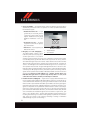
IMPORTANT
This User Guide is intended to familiarize you with the important
features of your vehicle. The DVD enclosed contains your Owner’s Manual,
Navigation/Uconnect Manuals, Warranty Booklets, Tire Warranty and
Roadside Assistance (new vehicles purchased in the U.S.) or Roadside
Assistance (new vehicles purchased in Canada) in electronic format. We
hope you find it useful. Replacement DVD kits may be purchased
by visiting www.techauthority.com.
The driver’s primary responsibility
moving is dangerous and could lead
is the safe operation of the vehicle.
to a serious collision. Texting while
Driving while distracted can result
driving is also dangerous and should
in loss of vehicle control, resulting
never be done while the vehicle is
in a collision and personal injury.
moving. If you find yourself unable
FCA US LLC strongly recommends
to devote your full attention to
that the driver use extreme caution
vehicle operation, pull off the road
when using any device or feature
to a safe location and stop your
that may take their attention off the
vehicle. Some states or provinces
road. Use of any electrical devices,
prohibit
such
telephones or texting while driving.
as
cellular
computers,
telephones,
portable
radios,
vehicle navigation or other
devices, by the driver
while the vehicle is
the
use
of
cellular
It is always the driver’s responsibility
to comply with all local laws.
DRIVESRT.COM (U.S.)
DRIVESRT.CA (CANADA)
DRIVING AND ALCOHOL
Drunken driving is one of the most frequent
This guide has been prepared to help you
get quickly acquainted with your new SRT
and to provide a convenient reference
source for common questions. However, it
is not a substitute for your Owner’s Manual.
For
complete
operational
instructions,
maintenance procedures and important
safety
messages,
Owner’s
please
Manual,
consult
your
Navigation/Uconnect
Manuals, and other Warning Labels in
your vehicle.
Not all features shown in this guide
may
apply
to
your
vehicle.
For
causes of accidents. Your driving ability can
be seriously impaired with blood alcohol
levels far below the legal minimum. If you
are drinking, don’t drive. Ride with a
designated non-drinking driver, call a cab,
a friend, or use public transportation.
WARNING!
Driving after drinking can lead to an
accident. Your perceptions are less sharp,
your reflexes are slower, and your judgment
is impaired when you have been drinking.
Never drink and then drive.
additional information on accessories to
help
personalize
www.mopar.com
(Canada)
or
your
vehicle,
(U.S.),
your
local
visit
www.mopar.ca
SRT
high
performance dealer.
1888387_16a_Viper_UG_051215.indd 2
5/12/15 10:45 AM
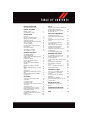
TABLE OF CONTENTS
INTRODUCTION/WELCOME
WELCOME FROM FCA US LLC
UTILITY
....... 2
CONTROLS AT A GLANCE
DRIVER COCKPIT . . . . . . . . . . . . . . . 4
INSTRUMENT CLUSTER . . . . . . . . . . . 6
GETTING STARTED
KEY FOB . . . . . . . . . . . . . . . . . . . . . 8
ENGINE STARTING/STOPPING . . . . . . . 9
VEHICLE SECURITY ALARM . . . . . . . . 10
SEAT BELT SYSTEMS . . . . . . . . . . . . 11
SUPPLEMENTAL RESTRAINT SYSTEM
(SRS) — AIR BAGS . . . . . . . . . . . . . 12
CHILD RESTRAINTS . . . . . . . . . . . . 21
NON-ADJUSTABLE HEAD RESTRAINTS . . . 24
FRONT SEATS . . . . . . . . . . . . . . . . 25
ADJUSTABLE PEDALS . . . . . . . . . . . 27
ADJUSTABLE FOOT REST . . . . . . . . . . 28
TILT STEERING COLUMN . . . . . . . . . 28
OPERATING YOUR VEHICLE
SRT ENGINE BREAK-IN
RECOMMENDATIONS . . . . . . . . . . .
TURN SIGNALS/WIPER/WASHER/HIGH
BEAMS LEVER . . . . . . . . . . . . . . .
HEADLIGHT SWITCH . . . . . . . . . . .
ELECTRONIC SPEED CONTROL . . . . .
LAUNCH MODE . . . . . . . . . . . . . . .
ELECTRONIC CONTROL DAMPING
SYSTEM . . . . . . . . . . . . . . . . . . .
ELECTRONIC STABILITY CONTROL
(ESC) . . . . . . . . . . . . . . . . . . . . .
MANUAL TRANSMISSION 1 TO 4 SKIP
SHIFT . . . . . . . . . . . . . . . . . . . .
ADDING FUEL . . . . . . . . . . . . . . .
AUTOMATIC TEMPERATURE CONTROL
(ATC) . . . . . . . . . . . . . . . . . . . . .
PARKVIEW REAR BACK UP CAMERA —
IF EQUIPPED . . . . . . . . . . . . . . . .
TRAILER TOWING WEIGHTS (MAXIMUM
TRAILER WEIGHT RATINGS) . . . . . . . 109
RECREATIONAL TOWING (BEHIND
MOTORHOME, ETC.) . . . . . . . . . . . . 109
WHAT TO DO IN EMERGENCIES
ROADSIDE ASSISTANCE . . . . . . .
INSTRUMENT CLUSTER WARNING
LIGHTS . . . . . . . . . . . . . . . .
INSTRUMENT CLUSTER INDICATOR
LIGHTS . . . . . . . . . . . . . . . .
IF YOUR ENGINE OVERHEATS . . .
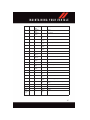
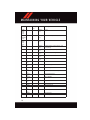
TIRE SERVICE KIT . . . . . . . . . .
JUMP-STARTING PROCEDURES . .
TOWING A DISABLED VEHICLE . .
FREEING A STUCK VEHICLE . . . .
ENHANCED ACCIDENT RESPONSE
SYSTEM (EARS) . . . . . . . . . . . .
EVENT DATA RECORDER (EDR) . .
. . . 110
. . . 110
.
.
.
.
.
.
.
.
.
.
.
.
.
.
.
.
.
.
114
115
116
121
123
124
. . . 125
. . . 125
MAINTAINING YOUR VEHICLE
. 29
.
.
.
.
30
31
32
34
. 35
. 36
. 37
. 37
. 40
. 42
ELECTRONICS
YOUR VEHICLE'S SOUND SYSTEM . . . . 44
YOUR RADIO . . . . . . . . . . . . . . . . . 46
UCONNECT ACCESS . . . . . . . . . . . . . 46
UCONNECT 8.4AN . . . . . . . . . . . . . . 58
UCONNECT 8.4AN VOICE RECOGNITION
QUICK TIPS . . . . . . . . . . . . . . . . . . 71
UCONNECT PHONE . . . . . . . . . . . . . 91
STEERING WHEEL AUDIO CONTROLS . . . 100
DRIVER INFORMATION DISPLAY (DID) . . . 101
PERFORMANCE PAGES . . . . . . . . . . 103
PROGRAMMABLE FEATURES . . . . . . . 104
UNIVERSAL GARAGE DOOR OPENER
(HomeLink) . . . . . . . . . . . . . . . . . 105
POWER OUTLETS . . . . . . . . . . . . . 108
TO OPEN AND CLOSE THE HOOD . . .
ENGINE COMPARTMENT — 8.4L . . .
FLUID CAPACITIES . . . . . . . . . . .
FLUIDS, LUBRICANTS, AND GENUINE
PARTS . . . . . . . . . . . . . . . . . . .
MAINTENANCE PROCEDURES . . . . .
MAINTENANCE SCHEDULES . . . . . .
FUSES . . . . . . . . . . . . . . . . . . .
TIRES — GENERAL INFORMATION . .
REPLACEMENT BULBS . . . . . . . . .
. 126
. 128
. 130
.
.
.
.
.
.
130
131
132
136
139
143
CONSUMER ASSISTANCE
FCA US LLC CUSTOMER CENTER . . .
FCA CANADA INC. CUSTOMER
CENTER . . . . . . . . . . . . . . . . . .
ASSISTANCE FOR THE HEARING
IMPAIRED . . . . . . . . . . . . . . . . .
PUBLICATIONS ORDERING . . . . . . .
REPORTING SAFETY DEFECTS IN THE
UNITED STATES . . . . . . . . . . . . .
. 144
. 144
. 144
. 144
. 145
MOPAR® ACCESSORIES
AUTHENTIC ACCESSORIES BY
MOPAR . . . . . . . . . . . . . . . . . . . 146
FREQUENTLY ASKED QUESTIONS
FREQUENTLY ASKED QUESTIONS . . . . 147
INDEX . . . . . . . . . . . . . . . . . . . . . 148
INTRODUCTION/WELCOME
WELCOME FROM FCA US LLC
Congratulations on selecting your new FCA US LLC (“FCA US”) vehicle. Be assured that
it represents precision workmanship, distinctive styling, and high quality - all essentials
that are traditional to our vehicles.
Your new FCA US vehicle has characteristics to enhance the driver's control under some
driving conditions. These are to assist the driver and are never a substitute for attentive
driving. They can never take the driver's place. Always drive carefully.
Your new vehicle has many features for the comfort and convenience of you and your
passengers. Some of these should not be used when driving because they take your eyes
from the road or your attention from driving. Never text while driving or take your eyes more
than momentarily off the road.
This guide illustrates and describes the operation of features and equipment that are
either standard or optional on this vehicle. This guide may also include a description of
features and equipment that are no longer available or were not ordered on this vehicle.
Please disregard any features and equipment described in this guide that are not available
on this vehicle. FCA US reserves the right to make changes in design and specifications
and/or make additions to or improvements to its products without imposing any obligation
upon itself to install them on products previously manufactured.
This User Guide has been prepared to help you quickly become acquainted with the
important features of your vehicle. It contains most things you will need to operate and
maintain the vehicle, including emergency information.
The DVD includes a computer application containing detailed Owner's information which
can be viewed on a personal computer or MAC computer. The multimedia DVD also
includes videos which can be played on any standard DVD player (including the Uconnect
Touchscreen Radios if equipped with DVD player capabilities). Additional DVD operational information is located on the back of the DVD sleeve.
For complete owner information, refer to your Owner's Manual on the DVD in the owner’s
kit provided at the time of new vehicle purchase. For your convenience, the information
contained on the DVD may also be printed and saved for future reference.
FCA US is committed to protecting our environment and natural resources. By converting
from paper to electronic delivery for the majority of the user information for your vehicle,
together we greatly reduce the demand for tree-based products and lessen the stress on
our environment.
2
INTRODUCTION/WELCOME
VEHICLES SOLD IN CANADA
With respect to any vehicles sold in Canada, the name FCA US LLC shall be deemed to be
deleted and the name FCA Canada Inc. used in substitution (excluding legal lines).
WARNING!
• Pedals that cannot move freely can cause loss of vehicle control and increase the
risk of serious personal injury.
• Always make sure that objects cannot fall into the driver foot well while the vehicle
is moving. Objects can become trapped under the brake pedal and accelerator
pedal causing a loss of vehicle control.
• Failure to properly follow floor mat installation or mounting can cause interference
with the brake pedal and accelerator pedal operation causing loss of control of the
vehicle.
• Never leave children alone in a vehicle, or with access to an unlocked vehicle.
Allowing children to be in a vehicle unattended is dangerous for a number of
reasons. A child or others could be seriously or fatally injured. Children should be
warned not to touch the parking brake, brake pedal or the transmission gear
selector.
• Do not leave the Key Fob in or near the vehicle, or in a location accessible to
children, and do not leave the ignition of a vehicle equipped with Keyless
Enter-N-Go in the ACC or ON/RUN mode. A child could operate power windows,
other controls, or move the vehicle.
• Never use the “PARK” position as a substitute for the parking brake. Always apply
the parking brake fully when parked to guard against vehicle movement and
possible injury or damage.
• Refer to your Owner's Manual on the DVD for further details.
USE OF AFTERMARKET PRODUCTS (ELECTRONICS)
The use of aftermarket devices including cell phones, MP3 players, GPS systems, or
chargers may affect the performance of on-board wireless features including Keyless
Enter-N-Go and Remote Start range. If you are experiencing difficulties with any of your
wireless features, try disconnecting your aftermarket devices to see if the situation
improves. If your symptoms persist, please see an authorized dealer.
When it comes to service, remember that your authorized dealer knows your vehicle best,
has factory-trained technicians and genuine MOPAR® parts, and cares about your
satisfaction.
3
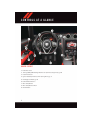
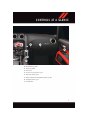
C O N T R O L S AT A G L A N C E
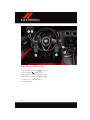
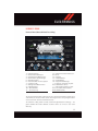
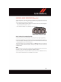
DRIVER COCKPIT
1. Power Door Locks
2. Turn Signal/Wiper/Washer/High Beams Lever (behind steering wheel) pg. 30
3. Instrument Cluster
4. Ignition Start/Stop Button (behind steering wheel) pg. 9
5. Identifying Your Radio pg. 46
6. Power Window Switches
7. Glove Compartment
8. Glove Compartment Switch
9. Hazard Button
4
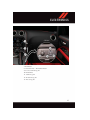
C O N T R O L S AT A G L A N C E
10. Power Outlet pg. 108
11. Emergency Brake
12. Shift Lever
13. Electronic Speed Control pg. 32
14. Adjustable Pedals pg. 27
15. Driver Information Display (DID) Controls pg. 101
16. Headlight Switch pg. 31
17. Power Mirrors
5
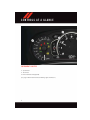
C O N T R O L S AT A G L A N C E
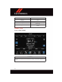
INSTRUMENT CLUSTER
1. Speedometer
2. Tachometer
3. Driver Information Display (DID)
(See page 110 for Instrument Cluster Warning Lights information.)
6
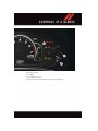
C O N T R O L S AT A G L A N C E
4. Oil Pressure Gauge
5. Fuel Gauge
6. Fuel Filler Door Location
(See page 114 for Instrument Cluster Indicator Lights information.)
7
GETTING STARTED
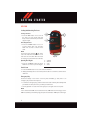
KEY FOB
Locking And Unlocking The Doors
Locking The Doors
• Push the LOCK button once to lock all
the doors. The turn signal lights will
flash, and the horn will chirp to acknowledge the signal.
Unlocking The Doors
• Push the UNLOCK button once to unlock the driver’s door only and twice
within five seconds to unlock all the
doors.
NOTE:
will illumiThe Door Unlock Indicator
nate in the instrument cluster when one or
both doors are unlocked. When the doors
are locked, the indicator will not illuminate.
Opening The Liftgate
• Push the LIFTGATE button two times
within five seconds to open the liftgate.
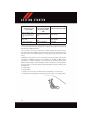
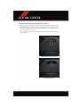
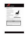
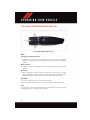
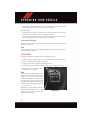
Key Fob
1 — Liftgate
2 — Unlock
3 — Lock
4 — Panic
Panic Alarm
1. Push the PANIC button once to turn the Panic Alarm on.
2. Wait approximately three seconds and push the button a second time to turn the Panic
Alarm off.
Emergency Key
Should the battery in the vehicle or the Key Fob transmitter go dead, there is an
emergency key located in the Key Fob.
• To remove the emergency key, slide the button at the back of the Key Fob sideways with
your thumb and then pull the key out with your other hand.
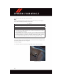
• The Key Cylinder is located in the rear applique to the right of the license plate.
NOTE:
In the event that the FOB does not start the vehicle ("FOB not Found" message), use the
FOB nose (furthest point from key ring) and push the start button. FOB replaces the finger.
8
GETTING STARTED
WARNING!
• Always apply the parking brake fully when parked to guard against vehicle movement and possible injury or damage.
• Never leave children alone in a vehicle, or with access to an unlocked vehicle.
Allowing children to be in a vehicle unattended is dangerous for a number of
reasons. A child or others could be seriously or fatally injured. Children should be
warned not to touch the parking brake, brake pedal or the transmission gear
selector.
• Do not leave the Key Fob in or near the vehicle, or in a location accessible to
children, and do not leave the ignition of a vehicle equipped with Keyless
Enter-N-Go in the ACC or ON/RUN mode. A child could operate power windows,
other controls, or move the vehicle
ENGINE STARTING/STOPPING
Starting
1. Fully apply the parking brake.
2. Push the clutch pedal to the floor.
3. Place the shift lever in NEUTRAL.
4. Push the red ENGINE START/STOP button located on the instrument panel.
Release the button when the engine
starts.
NOTE:
The engine will not start unless the clutch
pedal is pushed to the floor.
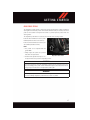
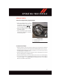
Stopping
Start/Stop Button
1. Bring the vehicle to a complete stop.
2. Fully apply the parking brake.
3. Push the clutch pedal to the floor.
4. Place the shift lever in NEUTRAL/1st Gear.
5. Push the ENGINE START/STOP button once. The ignition switch will return to the OFF
position.
9
GETTING STARTED
VEHICLE SECURITY ALARM
The Vehicle Security Alarm monitors the vehicle doors for unauthorized entry and the
ignition for unauthorized operation. While the Vehicle Security Alarm is armed, interior
switches for door locks and decklid release are disabled. If something triggers the alarm,
the Vehicle Security Alarm will provide the following audible and visible signals: the horn
will pulse, the park lamps and/or turn signals will flash, and the Vehicle Security Light in
the instrument cluster will flash.
To Arm:
Follow these steps to arm the Vehicle Security Alarm:
• Push LOCK on the interior power door lock switch with the driver and/or passenger door
open.
• Push the LOCK button on the Remote Keyless Entry (RKE) transmitter.
• The Vehicle Security Light in the instrument cluster will flash for 16 seconds. This
shows that the Vehicle Security Alarm is arming. During this period, if a door is opened,
the ignition is cycled to ON/RUN, or the power door locks are unlocked in any manner,
the Vehicle Security Alarm will automatically disarm.
NOTE:
• During the 16-second arming period, if a door is opened or the ignition is cycled to
ON/RUN, the Vehicle Security Alarm will automatically disarm.
• Once armed, the Vehicle Security Alarm disables the unlock switch on the driver door
trim panel and passenger door trim panel.
• Using the key to open the liftgate while the Vehicle Security Alarm is armed will not
trigger the theft alarm.
To Disarm:
The Vehicle Security Alarm can be disarmed using any of the following methods:
• Push the UNLOCK button on the Remote Keyless Entry (RKE) transmitter.
• Cycle the vehicle ignition system out of the OFF position.
10
GETTING STARTED
SEAT BELT SYSTEMS
Lap/Shoulder Belts
• All seating positions in your vehicle are equipped with lap/shoulder belts.
• Be sure everyone in your vehicle is in a seat and using a seat belt properly.
• Position the lap belt so that it is snug and lies low across your hips, below your
abdomen. To remove slack in the lap belt portion, pull up on the shoulder belt. To loosen
the lap belt if it is too tight, tilt the latch plate and pull on the lap belt. A snug seat belt
reduces the risk of sliding under the seat belt in a collision.
• Position the shoulder belt across the shoulder and chest with minimal, if any slack so
that it is comfortable and not resting on your neck. The retractor will withdraw any slack
in the shoulder belt.
Seat Belt Pretensioner
• The front seat belt system is equipped with pretensioning devices that are designed to
remove slack from the seat belt in the event of a collision.
• A deployed pretensioner or a deployed air bag must be replaced immediately.
WARNING!
• In a collision, you and your passengers can suffer much greater injuries if you are
not properly buckled up. You can strike the interior of your vehicle or other
passengers, or you can be thrown out of the vehicle. Always be sure you and others
in your vehicle are buckled up properly.
• A shoulder belt placed behind you will not protect you from injury during a collision.
You are more likely to hit your head in a collision if you do not wear your shoulder
belt. The lap and shoulder belt are meant to be used together.
• A seat belt that is too loose will not protect you properly. In a sudden stop, you could
move too far forward, increasing the possibility of injury. Wear your seat belt snugly.
• A frayed or torn seat belt could rip apart in a collision and leave you with no
protection. Inspect the seat belt system periodically, checking for cuts, frays, or
loose parts. Damaged parts must be replaced immediately. Do not disassemble or
modify the system. Seat belt assemblies must be replaced after a collision.
11
GETTING STARTED
SUPPLEMENTAL RESTRAINT SYSTEM (SRS) — AIR BAGS
Air Bag System Components
Your vehicle may be equipped with the following air bag system components:
• Occupant Restraint Controller (ORC)
• Air Bag Warning Light
• Steering Wheel and Column
• Instrument Panel
• Knee Impact Bolsters
• Advanced Front Air Bags
• Supplemental Side Air Bags
• Front and Side Impact Sensors
• Seat Belt Pretenioners
• Seat Belt Buckle Switch
• Seat Track Position Sensors
• Occupant Classification System
Advanced Front Air Bags
• This vehicle has Advanced Front Air Bags for both the driver and front passenger as a
supplement to the seat belt restraint systems. The Advanced Front Air Bags will not
deploy in every type of collision.
• Advanced Front Air Bags are designed to provide additional protection by supplementing the seat belts. Advanced Front Air Bags are not expected to reduce the risk of injury
in rear, side, or rollover collisions.
• The Advanced Front Air Bags will not deploy in all frontal collisions, including some
that may produce substantial vehicle damage — for example, some pole collisions,
truck underrides, and angle offset collisions.
• On the other hand, depending on the type and location of impact, Advanced Front Air
Bags may deploy in crashes with little vehicle front-end damage but that produce a
severe initial deceleration.
• Because air bag sensors measure vehicle deceleration over time, vehicle speed and
damage by themselves are not good indicators of whether or not an air bag should have
deployed.
• Seat belts are necessary for your protection in all collisions, and also are needed to help
keep you in position, away from an inflating air bag.
• After any collision, the vehicle should be taken to an authorized dealer immediately.
• Do not drive your vehicle after the air bags have deployed. If you are involved in another
collision, the air bags will not be in place to protect you.
12
GETTING STARTED
• If it is necessary to modify the air bag system for persons with disabilities, contact your
authorized dealer.
• Refer to the Owner's Manual on the DVD for further details regarding the Supplemental
Restraint System (SRS).
Occupant Classification System (OCS) – Front Passenger Seat
This vehicle is equipped with a right front passenger Occupant Classification System
(“OCS”) that is designed to activate or deactivate the Passenger Advanced Front Air Bag
depending on the occupant’s seated weight.
It is designed to deactivate the Passenger Advanced Front Air Bag for an unoccupied seat
and for occupants whose seated weight classifies them in a category other than a properly
seated adult. This could be a child, teenager, or even an adult.
The Occupant Classification System (OCS) consists of the following:
• Occupant Restraint Controller (ORC)
• Occupant Classification Module (OCM) and Sensor located in the front passenger seat
• Passenger Air Bag Disabled (PAD) Indicator Light – an amber light located in the center
of the instrument panel
• Air Bag Warning Light
The OCS may deactivate the deployment of the Passenger Advanced Front Air Bag if the
OCS estimates that:
• The front passenger seat is unoccupied or has very light objects in it.
• The front passenger seat is occupied by a rear-facing child restraint.
• The front passenger seat is occupied by a child, including a child seated in a
forward-facing child restraint or booster seat.
• The front passenger seat is occupied by a small passenger, including a child or small
adult.
• The front passenger is not properly seated or his or her weight is taken off of the seat
for a period of time.
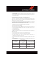
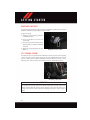
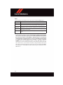
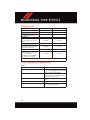
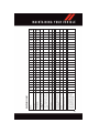
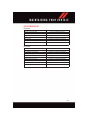
Front Passenger Seat
Occupant Status
Unoccupied Seat*
Grocery bags, heavy briefcases, and other relatively
light objects
Rear-facing child restraint**
Front Passenger Advanced Air Bag Disabled
Indicator Light (“PAD”)
Status
NOT ILLUMINATED
Front Passenger Air Bag Output
DEACTIVATED
“PASSENGER AIR BAG
OFF”
DEACTIVATED
“PASSENGER AIR BAG
OFF”
DEACTIVATED
13
GETTING STARTED
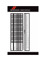
Front Passenger Seat
Occupant Status
Child, including a child
seated in a forward-facing
child restraint or booster
seat**
Small adult
Properly seated adult
Front Passenger Advanced Air Bag Disabled
Indicator Light (“PAD”)
Status
“PASSENGER AIR BAG
OFF”
“PASSENGER AIR BAG
OFF”
NOT ILLUMINATED
Front Passenger Air Bag Output
DEACTIVATED
DEACTIVATED
ACTIVATED
* When the front passenger seat is empty or when very light objects are placed on the seat,
the Passenger Advanced Front Air Bag will not deploy even though the PAD System
Indicator Light is NOT illuminated.
**It is possible for a child to be classified as an adult, allowing the deployment of the
Passenger Advanced Front Air Bag. Never allow children to ride in the front passenger seat
and never install a child restraint system, including a rear-facing child restraint, in this
vehicle.
The OCM uses input from the Sensor to determine the front passenger’s most probable
classification. The OCM communicates this information to the ORC. The ORC uses the
classification to determine whether it should activate or deactivate the Passenger
Advanced Front Air Bag. In order for the OCS to operate as designed, it is important for the
front passenger to be seated properly and properly wearing the seat belt. Properly seated
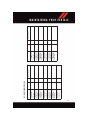
passengers are:
• Sitting upright.
• Facing forward.
• Sitting in the center of the seat with their feet comfortably on or near the floor.
• Sitting with their back against the seat back and the seat back in an upright position.
Seated Properly
14
GETTING STARTED
Passenger Advanced Front Air Bag Disabled (PAD) Indicator Light
2
The Passenger Advanced Front Air Bag (PAD) Indicator Light (an amber light located in
the center of the instrument panel) tells the driver and front passenger when the
Passenger Advanced Front Air Bag is deactivated. The PAD Indicator light illuminates the
words “PASSENGER AIR BAG OFF” to show that the Passenger Advanced Front Air Bag
will not deploy during a collision. When the front passenger seat is empty or when very
light objects are placed on the seat, the Passenger Advanced Front Air Bag will not deploy
even though the PAD indicator light is NOT illuminated.
The PAD indicator light should not be illuminated when an adult passenger is properly
seated in the front passenger seat. The driver and adult passenger should verify that the
PAD Indicator Light is not illuminated when an adult is riding in the front passenger seat.
If an adult is not seated properly, the Passenger Advanced Front Air Bag may deactivate
and the PAD Indicator Light will be illuminated.
The PAD Indicator Light should be illuminated and the Passenger Advanced Front Air Bag
should be deactivated for most properly seated and restrained children in the passenger
seat and for most properly installed child restraint systems. However, under certain
conditions, even with a properly installed child restraint system, the PAD Indicator Light
may not be illuminated, even though the Passenger Advanced Front Air Bag is deactivated. This can occur if the child restraint is lighter than the lightest weight necessary to
illuminate the PAD Indicator Light. NEVER assume the Passenger Advanced Front Air Bag
is deactivated unless the PAD Indicator Light is illuminated with the words “PASSENGER
AIR BAG OFF.”
If an adult passenger is seated in the front passenger seat and the PAD Indicator Light is
illuminated, the passenger may be sitting improperly. Follow the steps below to allow the
OCS to detect the adult passenger’s seated weight to activate the Passenger Advanced
Front Air Bag:
1. Turn off the vehicle and have the adult passenger step out of the vehicle.
2. Remove any extra materials from the passenger seat, such as cushions, pads, seat
covers, seat massagers, blankets, extra clothing, etc.
3. Place the seatback in the full upright position.
4. Have the adult passenger sit in the center of the seat, with the passenger’s feet
comfortably on or near the floor, and with their back against the seatback.
5. Restart the vehicle and have the passenger remain in this seated position for two to
three minutes after restarting the vehicle.
15
GETTING STARTED
WARNING!
If the PAD Indicator Light remains illuminated for an adult passenger, have an
authorized dealer service the air bag system immediately. Failure to do so may cause
serious injury or death. If the PAD Indicator Light is illuminated with the words
“PASSENGER AIR BAG OFF,” the Passenger Advanced Front Air Bag will not deploy in
the event of a collision.
Lighter Weight Passengers (Including Small Adults)
When a lighter weight passenger, including a small adult occupies the passenger seat, the
Passenger Advanced Front Air Bag may be deactivated. Therefore, the Passenger Advanced Front Air Bag may or may not be activated for a lighter weight passenger, including
a small adult (depending on size) who is seated in the passenger seat. This does not mean
that the OCS is working improperly.
The driver and passenger must always use the PAD Indicator Light as a determination of
whether the Passenger Advanced Front Air Bag is activated or deactivated. If the PAD
Indicator Light is illuminated with the words “PASSENGER AIR BAG OFF” when an adult
is in the front passenger seat, have the passenger reposition his or her body in the seat
until the PAD Indicator Light goes out.
If the PAD Indicator Light is illuminated with the words “PASSENGER AIR BAG OFF” the
Passenger Advanced Front Air Bag will not inflate in the event of a collision.
Do not decrease OR increase the front passenger’s seated weight on the front passenger seat
The front passenger’s seated weight must be properly positioned on the front passenger
seat. Failure to do so may result in serious injury or death. The OCS determines the most
probable classification of the occupant that it detects. The OCS will detect the front
passenger’s decreased or increased seated weight, which may result in deactivation or
activation of the Passenger Advanced Front Air Bag in a collision. This does not mean that
the OCS is working improperly. Decreasing the front passenger’s seated weight on the front
passenger seat may result in deactivation of the Passenger Advanced Front Air Bag
causing serious injury or death. Increasing the front passenger’s seated weight on the front
passenger seat may result in activation of the Passenger Advanced Front Air Bag.
Examples of improper front passenger seating include:
• The front passenger’s weight is transferred to another part of the vehicle (like the door,
arm rest or instrument panel).
• The front passenger leans forward, sideways or turns to face the rear of the vehicle.
• The front passenger’s seatback is not in the full upright position.
• The front passenger carries or holds an object while seated (e.g., backpack, box, etc.).
• Objects are lodged under the front passenger seat.
• Objects are lodged between the front passenger seat and center console.
• Accessories that may change the seated weight on the front passenger seat are
attached to the front passenger seat.
• Anything that may decrease or increase the front passenger’s seated weight.
16
GETTING STARTED
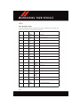
The OCS determines the front passenger’s most probable classification. If an occupant in
the front passenger seat is seated improperly, the occupant may provide an output signal
to the OCS that is different from the occupant’s properly seated weight input, for example:
Not Seated Properly
Not Seated Properly
Not Seated Properly
Not Seated Properly
17
GETTING STARTED
The Air Bag Warning Light
front passenger seat status.
will illuminate whenever the OCS is unable to classify the
A malfunction in the OCS may affect the operation of the air bag system. If the Air Bag
Warning Light
does not come on, or stays on after you start the vehicle, or it comes
on as you drive, take the vehicle to an authorized dealer for service immediately.
WARNING!
• Ignoring the Air Bag Warning Light in your instrument panel could mean you won’t
have the air bags to protect you in a collision. If the light does not come on as a bulb
check when the ignition is first turned on, stays on after you start the vehicle, or if
it comes on as you drive, have an authorized dealer service the air bag system
immediately.
• Placing an object on the floor under the front passenger seat may prevent the OCS
from working properly, which may result in serious injury or death in a collision. Do
not place any objects on the floor under the front passenger seat.
• If there is a fault present in the OCS, both the PAD Indicator Light and the Air Bag
Warning Light will illuminate to show that the Passenger Advanced Front Air Bag is
deactivated. Should this occur, the Passenger Advanced Front Air Bag will remain
deactivated until the fault is cleared. This indicates that you should take the vehicle
to an authorized dealer for service immediately.
The passenger seat assembly contains critical OCS components that may affect Passenger Advanced Front Air Bag inflation. In order for the OCS to properly classify the seated
weight of a front seat passenger, the OCS components must function as designed.
Do not make any modifications to the front passenger seat components, assembly, or to
the seat cover. If the seat, trim cover, or cushion needs service for any reason, take the
vehicle to your authorized dealer. Only FCA US LLC approved seat accessories may be
used.
The following requirements must be strictly followed:
• Do not modify the front passenger seat assembly or components in any way.
• Do not use prior or future model year seat covers or cushions not designated by FCA US
LLC for the specific model being repaired. Always use the correct seat cover and
cushion specified for the vehicle.
• Do not replace the seat cover or cushion with an aftermarket seat cover or cushion.
• Do not add a secondary seat cover or mat.
• At no time should any supplemental restraint system (SRS) component or SRS related
component or fastener be modified or replaced with any part except those which are
approved by FCA US LLC.
18
GETTING STARTED
WARNING!
• Relying on the air bags alone could lead to more severe injuries in a collision. The
air bags work with your seat belt to restrain you properly. In some collisions, the air
bags won't deploy at all. Always wear your seat belts even though you have air bags.
• Being too close to the steering wheel or instrument panel during Advanced Front Air
Bag deployment could cause serious injury, including death. Air bags need room to
inflate. Sit back, comfortably extending your arms to reach the steering wheel or
instrument panel.
• No objects should be placed over or near the air bag on the instrument panel or
steering wheel because any such objects could cause harm if the vehicle is in a
collision severe enough to cause the air bag to inflate.
Supplemental Side Air Bags
• This vehicle is equipped with Supplemental Door-Integrated Side Air Bag Inflatable
Curtains (SABICs). The SABICs are located in the door trim below the side windows.
The trim covering the SABICs is labeled SRS AIRBAG or AIRBAG.
• The SABICs may help reduce the risk of partial or complete ejection of vehicle
occupants through side windows in certain side impact events.
• SABICs are designed to activate in certain side impacts. The Occupant Restraint
Controller (“ORC”) determines whether the deployment of the SABIC in a particular
impact event is appropriate, based on the severity and type of collision. Vehicle damage
by itself is not a good indicator of whether or not SABICs should have deployed.
WARNING!
• Relying on the SABICs alone could lead to more severe injuries in a collision. The
SABICs work with your seat belt to restrain you properly. In some collisions, SABICs
won’t deploy at all. Always wear your seat belt even though you have SABICs.
• SABICs need room to inflate. Do not lean against the door or window. Sit upright in
the center of the seat.
• Being too close to the SABICs during deployment could cause you to be severely
injured or killed.
• This vehicle is equipped with left and right Supplemental Door-Integrated Side Air
Bag Inflatable Curtains (SABICs). Do not stack luggage or other cargo up high
enough to block the deployment of the SABICs. The door trim below the side
windows where the SABIC and its deployment path are located, should remain free
from any obstructions.
19
GETTING STARTED
Enhanced Accident Response System
In the event of an impact, if the communication network remains intact, and the power
remains intact, depending on the nature of the event, the ORC will determine whether to
have the Enhanced Accident Response System perform the following functions:
• Cut off fuel to the engine.
• Flash hazard lights as long as the battery has power or until the hazard light button is
pushed. The hazard lights can be deactivated by pushing the hazard light button.
• Turn on the interior lights, which remain on as long as the battery has power.
• Unlock the power door locks.
Enhanced Accident Response System Reset Procedure
In order to reset the Enhanced Accident Response System functions after an event, the
ignition switch must be changed from ignition START or ON/RUN to ignition OFF.
Carefully check the vehicle for fuel leaks in the engine compartment and on the ground
near the engine compartment and fuel tank before resetting the system and starting the
engine.
Air Bag Warning Light
• The air bags must be ready to inflate for your protection in a collision. The Occupant
Restraint Controller (ORC) monitors the internal circuits and interconnecting wiring
associated with air bag system electrical components.
• The ORC monitors the readiness of the electronic parts of the air bag system whenever
the ignition switch is in the START or ON/RUN position. If the ignition switch is in the
OFF position or in the ACC position, the air bag system is not on and the air bags will
not inflate.
• The ORC turns on the Air Bag Warning Light in the instrument panel for approximately
four to eight seconds for a self-check when the ignition switch is first turned to the
ON/RUN position. After the self-check, the Air Bag Warning Light will turn off. If the
ORC detects a malfunction in any part of the system, it turns on the Air Bag Warning
Light, either momentarily or continuously. A single chime will sound to alert you if the
light comes on again after initial startup.
• If the Air Bag Warning Light in the instrument panel is not on during the four to eight
seconds when the ignition switch is first turned to the ON/RUN position, stays on, or
turns on while driving, have the vehicle serviced by an authorized service center
immediately.
NOTE:
If the speedometer, tachometer, or any engine related gauges are not working, the
Occupant Restraint Controller (ORC) may also be disabled. In this condition the air bags
may not be ready to inflate for your protection. Have an authorized dealer service the air
bag system immediately.
20
GETTING STARTED
Event Data Recorder (EDR)
This vehicle is equipped with an event data recorder (EDR). The main purpose of an EDR
is to record, in certain crash or near crash-like situations, such as an air bag deployment
or hitting a road obstacle, data that will assist in understanding how a vehicle’s systems
performed. The EDR is designed to record data related to vehicle dynamics and safety
systems for a short period of time, typically 30 seconds or less. The EDR in this vehicle is
designed to record such data as:
• How various systems in your vehicle were operating;
• Whether or not the driver and passenger safety belts were buckled/fastened;
• How far (if at all) the driver was depressing the accelerator and/or brake pedal; and,
• How fast the vehicle was traveling.
These data can help provide a better understanding of the circumstances in which crashes
and injuries occur.
NOTE:
EDR data are recorded by your vehicle only if a non-trivial crash situation occurs; no data
are recorded by the EDR under normal driving conditions and no personal data (e.g.,
name, gender, age, and crash location) are recorded. However, other parties, such as law
enforcement, could combine the EDR data with the type of personally identifying data
routinely acquired during a crash investigation.
To read data recorded by an EDR, special equipment is required, and access to the vehicle
or the EDR is needed. In addition to the vehicle manufacturer, other parties, such as law
enforcement, that have the special equipment, can read the information if they have
access to the vehicle or the EDR.
CHILD RESTRAINTS
Children 12 years or younger should ride properly buckled up in a rear seat, if available.
According to crash statistics, children are safer when properly restrained in the rear seats
rather than in the front.
Every state in the United States and all Canadian provinces require that small children
ride in proper restraint systems. This is the law, and you can be prosecuted for ignoring it.
NOTE:
• For additional information, refer to www.Seatcheck.org or call 1-866-SEATCHECK
(1-866-732-8243 ).
• Canadian residents should refer to Transport Canada’s website for additional information: http://www.tc.gc.ca/eng/motorvehiclesafety/safedrivers-childsafety-index-53.htm
21
GETTING STARTED
Installing the Child Restraint Using the Vehicle Seat Belts
• The front passenger seating position is equipped with a Switchable Automatic Locking
Retractor (ALR) that is designed to keep the lap portion of the seat belt tight around the
child restraint. Any seat belt system will loosen with time, so check the belt occasionally, and pull it tight if necessary.
• There is a tether strap anchor located behind the child tether access cover behind the
passenger seat.
Child Tether Anchorage Access Cover
Child Tether Anchorage
22
GETTING STARTED
Tether Anchorage Weight Limit
Always use the tether anchor when using the seat belt to install a forward facing child
restraint, up to the recommended weight limit of the child restraint.
To Install A Child Seat Using An ALR:
1. Pull enough of the seat belt webbing from the retractor to pass it through the belt path
of the child restraint. Do not twist the belt webbing in the belt path.
2. Slide the latch plate into the buckle until you hear a “click.”
3. Pull on the webbing to make the lap portion tight against the child seat.
4. To lock the seat belt, pull down on the shoulder part of the belt until you have pulled
all the seat belt webbing out of the retractor. Then, allow the webbing to retract back
into the retractor. As the webbing retracts, you will hear a clicking sound. This means
the seat belt is now in the Automatic Locking mode.
5. Try to pull the webbing out of the retractor. If it is locked, you should not be able to pull
out any webbing. If the retractor is not locked, repeat the last step.
6. Finally, pull up on any extra webbing to tighten the lap portion around the child
restraint while you push the child restraint rearward and downward into the vehicle
seat.
7. If the child restraint has a top tether strap and the seating position has a top tether
anchorage, connect the tether strap to the anchorage and tighten the tether strap. See
below for directions to attach a tether anchor.
8. Test that the child restraint is installed tightly by pulling back and forth on the child
seat at the belt path. It should not move more than 1 inch (25.4 mm) in any direction.
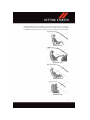
Installing the Top Tether Strap with the Vehicle Seat Belt:
When installing a forward-facing child restraint, always secure the top tether strap, up to
the tether anchor weight limit, when the child restraint is installed with the vehicle seat
belt.
Tether Strap Installation
There is a tether strap anchor located behind the child tether access cover behind the
passenger seat. To attach a child restraint tether strap to the anchor:
1. Move the seat forward.
2. Move the seatback to its full forward position.
3. Remove the child tether access cover by prying either side with a screwdriver or similar
tool, as shown.
NOTE:
While the child tether is in use, keep the access cover in a safe place so that it can be
replaced after use of the child tether.
23
GETTING STARTED
4. Pass the child restraint tether hook through either opening in the seatback underneath
the head restraint.
5. Attach the tether hook to the anchor loop.
6. Move the seat to its farthest rearward position. Apply body pressure to the seat to be
sure the seat adjusters have latched.
7. Return the seatback to an upright position.
8. Remove slack from the tether strap according to the child restraint manufacturer’s
directions.
WARNING!
• In a collision, an unrestrained child, even a tiny baby, can become a projectile
inside the vehicle. The force required to hold even an infant on your lap could
become so great that you could not hold the child, no matter how strong you are.
The child and others could be severely injured or killed. Any child riding in your
vehicle should be in a proper restraint for the child's size.
• Never place a rear-facing child restraint in front of an air bag. A deploying Passenger
Advanced Front Air Bag can cause death or serious injury to a child 12 years or
younger, including a child in a rear-facing child restraint.
• Only use a rear-facing child restraint in a vehicle with a rear seat.
• Improper installation of a child restraint to the LATCH anchorages can lead to
failure of an infant or child restraint. The child could be severely injured or killed.
Follow the manufacturer’s directions exactly when installing an infant or child
restraint.
• An incorrectly anchored tether strap could lead to increased head motion and
possible injury to the child. Use only the anchor positions directly behind the child
seat to secure a child restraint top tether strap.
• If your vehicle is equipped with a split rear seat, make sure the tether strap does not
slip into the opening between the seatbacks as you remove slack in the strap.
NON-ADJUSTABLE HEAD RESTRAINTS
The non-adjustable head restraints are form fitted into the upper structure of the seatback
and are designed to reduce the risk of injury by restricting head movement in the event of
a rear impact. The seatback should be properly adjusted to an upright position where the
head restraint is positioned as close as possible to the back of your head.
WARNING!
Be certain that the seatback is locked securely into position. Otherwise, the seat will
not provide the proper stability for passengers. An improperly latched seatback could
cause serious injury.
24
GETTING STARTED
FRONT SEATS
Power Seats
On models equipped with power seats, the
power seat switch is located on the outboard side of the seat near the floor.
Adjusting The Seat Forward Or Rearward
The seat can be adjusted both forward and
rearward. Push the seat switch forward or
rearward. The seat will move in the direction of the switch. Release the switch when
the desired position has been reached.
Power Seat Switches
Adjusting The Seat Up Or Down
1 — Power Recline Switch
The height of the seats can be adjusted up 2 — Power Seat Switch
or down. Pull upward or push downward on
the seat switch, the seat will move in the
direction of the switch. Release the switch when the desired position is reached.
Reclining The Seatback Forward Or Rearward
The seatback can be reclined both forward and rearward. Push the power seat recliner
switch forward or rearward, the seatback will move in the direction of the switch. Release
the switch when the desired position has been reached.
WARNING!
• Adjusting a seat while driving may be dangerous. Moving a seat while driving could
result in loss of control which could cause a collision and serious injury or death.
• Seats should be adjusted before fastening the seat belts and while the vehicle is
parked. Serious injury or death could result from a poorly adjusted seat belt.
• Do not ride with the seatback reclined so that the shoulder belt is no longer resting
against your chest. In a collision you could slide under the seat belt, which could
result in serious injury or death.
CAUTION!
Do not place any article under a power seat or impede its ability to move as it may cause
damage to the seat controls. Seat travel may become limited if movement is stopped
by an obstruction in the seat’s path.
25
GETTING STARTED
Manual Seats
Forward And Rearward Adjustment
The adjusting bar is at the front of the seat,
near the floor. Pull the bar upward to move
the seat forward or rearward. Release the
bar once the seat is in the desired position.
Then, using body pressure, move forward
and rearward on the seat to be sure that the
seat adjusters have latched.
Seat Height Adjustment
The seat height adjustment lever is located
on the outboard side of the seat. Pull upward on the lever to raise the seat height or
push downward on the lever to lower the
seat height.
Recliner Adjustment
Seat Adjustments
1 — Seat Adjustment Bar
2 — Recline Lever
3 — Height Adjustment Lever
The recliner lever is located on the outboard
side of the seat. To recline the seat, lean forward slightly, pull the recliner lever upward,
lean backward until the seat is in the desired position, and release the lever. To return the
seat to its full upright position, lean forward, pull the recliner lever upward and hold it until
the seat returns to its full upright position.
WARNING!
• Adjusting a seat while driving may be dangerous. Moving a seat while driving could
result in loss of control which could cause a collision and serious injury or death.
• Seats should be adjusted before fastening the seat belts and while the vehicle is
parked. Serious injury or death could result from a poorly adjusted seat belt.
• Do not ride with the seatback reclined so that the shoulder belt is no longer resting
against your chest. In a collision you could slide under the seat belt, which could
result in serious injury or death.
26
GETTING STARTED
ADJUSTABLE PEDALS
The adjustable pedals system is designed to allow a greater range of driver comfort for
steering wheel tilt and seat position. This feature allows the brake, accelerator, and clutch
pedal to move toward or away from the driver to provide improved position with the
steering wheel.
The adjustable pedal switch is located to the left side of the steering column.
Push the switch forward to move the pedals
forward (toward the front of the vehicle).
Push the switch rearward to move the pedals rearward (toward the driver).
NOTE:
• The pedals can be adjusted with the
ignition OFF.
• Always adjust the pedals to a position
that allows full pedal travel.
Adjustable Pedal Switch
• Further small adjustments may be necessary to find the best possible seat/pedal position.
CAUTION!
Do not place any article under the adjustable pedals or impede its ability to move as it
may cause damage to the pedal controls. Pedal travel may become limited if movement
is stopped by an obstruction in the adjustable pedal's path.
WARNING!
Do not adjust the pedals while the vehicle is moving. You could lose control and have
an accident. Always adjust the pedals while the vehicle is parked.
27
GETTING STARTED
ADJUSTABLE FOOT REST
This feature allows the driver to adjust the foot rest forward or backward and to rotate it
upward or downward to allow for greater driving comfort.
To adjust the pedal:
1. Adjust the seat and steering column to a
comfortable position.
2. Using a socket wrench, loosen the nut
on the pedal.
3. Slide the pedal either forward or backward and rotate it upward or downward
as desired.
4. Tighten the nut, being careful not to over
tighten it.
Adjustable Foot Rest Location
TILT STEERING COLUMN
The tilt release lever is located below the multifunction lever on the left side of the steering
column. To tilt the column, simply pull the release lever rearward toward you and then
move the steering wheel upward or downward as desired. When the column is in the
desired position, push the release lever forward to lock the column firmly in place.
Tilt Steering Column Lever
WARNING!
Do not adjust the steering column while driving. Adjusting the steering column while
driving or driving with the steering column unlocked, could cause the driver to lose
control of the vehicle. Failure to follow this warning may result in serious injury or
death.
28
O P E R AT I N G Y O U R V E H I C L E
SRT ENGINE BREAK-IN RECOMMENDATIONS
SRT Engine Break-In Recommendations: The following tips will be helpful in obtaining
optimum performance and maximum durability for your new SRT Vehicle.
Despite modern technology and World Class manufacturing methods, the moving parts of
the vehicle must still wear in with each other. This wearing in occurs mainly during the first
500 miles (805 km) and continues through the first oil change interval.
It is recommended for the operator to observe the following driving behaviors during the
new vehicle break-in period:
0 to 100 miles (0 to 161 km):
• Do not allow the engine to operate at idle for an extended period of time.
• Depress the accelerator pedal slowly and not more than halfway to avoid rapid
acceleration.
• Avoid aggressive braking.
• Drive with the engine speed less than 3,500 RPM.
• Maintain vehicle speed below 55 mph (88 km/h) and observe local speed limits.
100 to 300 miles (161 to 483 km):
• Depress the accelerator pedal slowly and not more than halfway to avoid rapid
acceleration in lower gears (1st to 3rd gears).
• Avoid aggressive braking.
• Drive with the engine speed less than 5,000 RPM.
• Maintain vehicle speed below 70 mph (112 km/h) and observe local speed limits.
300 to 500 miles (483 to 805 km):
• Exercise the full engine rpm range, shifting manually (paddles or gear shift) at higher
rpms when possible.
• Do not perform sustained operation with the accelerator pedal at wide open throttle.
• Maintain vehicle speed below 85 mph (136 km/h) and observe local speed limits.
For the first 1500 mi (2414 km):
• Do not participate in track events, sport driving schools, or similar activities during the
first 1500 mi (2414 km).
NOTE:
Check engine oil with every refueling and add if necessary. Oil and fuel consumption may
be higher through the first oil change interval.
29
O P E R AT I N G Y O U R V E H I C L E
TURN SIGNALS/WIPER/WASHER/HIGH BEAMS LEVER
Turn Signal/Wiper/Washer/High Beam Lever
Wipers
Intermittent, Low And High Operation
• Rotate the end of the lever to the first detent position for one of five intermittent
settings, the second detent for low wiper operation and the third detent for high wiper
operation.
Washer Operation
• Push the end of the lever inward to the second detent and hold for as long as spray is
desired.
Mist Feature
• When a single wipe to clear off road mist or spray from a passing vehicle is needed,
push the washer knob, located on the end of the multifunction lever, inward to the first
detent and release. The wipers will cycle one time and automatically shut off.
High Beams
• Push the lever away from you to activate the high beams.
A high beam symbol will illuminate in the cluster to indicate the high beams are on.
NOTE:
For safe driving, turn off the high beams when oncoming traffic is present to prevent
headlight glare and as a courtesy to other motorists.
30
O P E R AT I N G Y O U R V E H I C L E
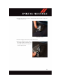
HEADLIGHT SWITCH
Automatic Headlights/Parking Lights/Headlights
• Rotate the headlight switch, located on
the instrument panel to the left of the
steering wheel, to the first detent from the
and to
off position for parking light
.
the second detent for headlight
• Rotate the headlight switch to “AUTO”
for AUTO headlights.
• When set to AUTO, the system automatically turns the headlights on or off based
on ambient light levels.
Headlight Switch
1 — Rotate Headlight Switch
2 — Rotate Dimmer
Instrument Panel Dimmer
• Rotate the dimmer control to the extreme bottom position to fully dim the instrument
panel lights and prevent the interior lights from illuminating when a door is opened.
• Rotate the dimmer control up to increase the brightness of the instrument panel when
the parking lights or headlights are on.
• Rotate the dimmer control up to the next detent position to fully brighten the odometer
when the parking lights or headlights are on.
• Rotate the dimmer control up to the last detent position to turn on the interior lighting.
• The touchscreen dimming is programmable through the Uconnect system. Refer to
“Uconnect Settings ” in “Understanding Your Instrument Panel” in the Owner's
Manual on the DVD for further details.
31
O P E R AT I N G Y O U R V E H I C L E
ELECTRONIC SPEED CONTROL
When engaged, the Electronic Speed Control takes over accelerator operations at speeds
greater than 25 mph (40 km/h).
The Electronic Speed Control buttons are located on the right side of the steering wheel.
NOTE:
In order to ensure proper operation, the
Electronic Speed Control System has been
designed to shut down if multiple speed
control buttons are pushed at the same
time. If this occurs, the Electronic Speed
Control System can be reactivated by
pushing the Electronic Speed Control ON/
OFF button and resetting the desired vehicle set speed.
To Activate
Push the ON/OFF button to activate the
Electronic Speed Control. The Cruise Indicator Light in the Driver Information Display
(DID) will illuminate. To turn the system off,
push the ON/OFF button a second time.
The Cruise Indicator Light will turn off. The
system should be turned off when not in
use.
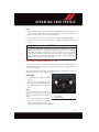
Electronic Speed Control Switches
1 — Push Cancel
2 — Push On/Off
3 — Push Resume/Accel
4 — Push Set/Decel
WARNING!
Leaving the Electronic Speed Control system on when not in use is dangerous. You
could accidentally set the system or cause it to go faster than you want. You could lose
control and have an accident. Always leave the system OFF when you are not using it.
To Set A Desired Speed
Turn the Electronic Speed Control ON. When the vehicle has reached the desired speed,
push the SET (-) button and release. Release the accelerator and the vehicle will operate
at the selected speed.
NOTE:
The vehicle should be traveling at a steady speed and on level ground before pushing
the SET (-) button.
32
O P E R AT I N G Y O U R V E H I C L E
To Deactivate
A soft tap on the brake pedal, pushing the CANCEL button, manually accelerating 10 mph
(16 km/h) above the set speed or normal brake pressure while slowing the vehicle will
deactivate the Electronic Speed Control without erasing the set speed memory.
Pushing the ON/OFF button or turning the ignition switch OFF erases the set speed
memory.
To Resume Speed
To resume a previously set speed, push the RES (+) button and release. Resume can be
used at any speed above 20 mph (32 km/h).
To Vary The Speed Setting
To Increase Speed
When the Electronic Speed Control is set, you can increase speed by pushing the RES (+)
button.
The drivers preferred units can be selected through the instrument panel settings if
equipped. Refer to “Understanding Your Instrument Panel” in the Owner’s Manual on the
DVD for more information. The speed increment shown is dependent on the selected
speed unit of U.S. (mph) or Metric (km/h):
U.S. Speed (mph)
• Pushing the RES (+) button once will result in a 1 mph increase in set speed. Each
subsequent tap of the button results in an increase of 1 mph.
• If the button is continually pushed, the set speed will continue to increase until the
button is released, then the new set speed will be established.
Metric Speed (km/h)
• Pushing the RES (+) button once will result in a 1 km/h increase in set speed. Each
subsequent tap of the button results in an increase of 1 km/h.
• If the button is continually pushed, the set speed will continue to increase until the
button is released, then the new set speed will be established.
To Decrease Speed
When the Electronic Speed Control is set, you can decrease speed by pushing the SET (-)
button.
The drivers preferred units can be selected through the instrument panel settings if
equipped. Refer to “Understanding Your Instrument Panel” in the Owner’s Manual on the
DVD for more information. The speed decrement shown is dependant on the selected
speed unit of U.S. (mph) or Metric (km/h):
U.S. Speed (mph)
• Pushing the SET (-) button once will result in a 1 mph decrease in set speed. Each
subsequent tap of the button results in a decrease of 1 mph.
33
O P E R AT I N G Y O U R V E H I C L E
• If the button is continually pushed, the set speed will continue to decrease until the
button is released, then the new set speed will be established.
Metric Speed (km/h)
• Pushing the SET (-) button once will result in a 1 km/h decrease in set speed. Each
subsequent tap of the button results in a decrease of 1 km/h.
• If the button is continually pushed, the set speed will continue to decrease until the
button is released, then the new set speed will be established.
To Accelerate For Passing
Push the accelerator as you would normally. When the pedal is released, the vehicle will
return to the set speed.
NOTE:
If the accelerated speed goes above 10 mph (16 km/h) of the set speed, the Electronic
Speed Control will deactivate.
LAUNCH MODE
This system maximizes acceleration traction for straight line racing.
1. Bring the vehicle to complete stop on a level track surface with the engine running.
2. Set the steering wheel for straight ahead driving.
3. Fully depress the clutch and select the first gear position.
4. Push and release the “LAUNCH” button (located on the steering wheel controls).
5. Rapidly press the accelerator pedal to
the floor within one second.
NOTE:
If the cluster launch DID message indicates
all conditions are correct for launch and the
throttle is pressed to the floor quickly
(within approximately 1/2 second) the system will hold the engine speed to a preset
speed (below the engine rev limiter speed).
6. Release the clutch aggressively. Do not
ride the clutch.
Release the accelerator pedal to deactivate
launch control. Pushing the launch control
button or actuating the brakes will also
deactivate launch control.
34
LAUNCH Button
O P E R AT I N G Y O U R V E H I C L E
NOTE:
• Launch Mode brings the engine to optimum launch RPM and waits for the driver to
release the clutch. Launch Mode then uses engine throttle only to achieve controlled
wheelslip for maximum acceleration through first gear.
• Launch Mode can be used in any of the Electronic Stability Control (ESC) Modes.
• Launch Mode should not be used within the first 500 miles (805 km) of engine
break-in.
WARNING!
Launch Mode is intended for off-highway or off-road use only and should not be used
on any public roadways. It is recommended that this feature be used in a controlled
environment, and within the limits of the law. The capabilities of the vehicle as
measured by the performance pages must never be exploited in a reckless or dangerous
manner, which can jeopardize the user’s safety or the safety of others. Only a safe,
attentive, and skillful driver can prevent accidents.
ELECTRONIC CONTROL DAMPING SYSTEM
This vehicle may be equipped with an Electronic Controlled Dampening system. This
system reduces body roll and pitch in many driving situations including cornering,
acceleration and braking.
This system allows for a street suspension damping setting or a firmer race suspension
damping setting. There are two modes of operation:
STREET MODE
• This mode will give a sporty, but comfortable ride.
• This mode is driver selectable when the
vehicle is placed in STREET mode (push
the “STREET” button on the Instrument
Panel).
NOTE:
The suspension mode will lock and stay in
whatever the driver selects even when the
ignition is turned off and the vehicle restarted.
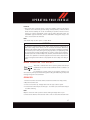
Mode Buttons
1 — RACE Button
2 — STREET Button
• This mode is intended for a smoother
ride on the various types of pavement
and road conditions while still providing
damping levels appropriate extreme capabilities.
35
O P E R AT I N G Y O U R V E H I C L E
RACE MODE
• Race mode is driver selectable when the vehicle is placed in RACE mode (push the
“RACE” button on the Instrument Panel).
• This mode is for track use only and will supply maximum grip to the tires.
• When RACE mode is enabled, a shock symbol with “RACE” next to it will light up in the
instrument cluster.
NOTE:
The RACE setting will provide a firmer ride.
ELECTRONIC STABILITY CONTROL (ESC)
The ESC corrects for oversteering and understeering the vehicle by applying the brake of
the appropriate wheel. Engine power may also be reduced to assist in counteracting the
condition of oversteer or understeer and help the vehicle maintain the desired path.
In full on mode ESC utilizes sensors in the vehicle to determine the path that the driver
intends to steer the vehicle and compares it to the actual path of the vehicle. When the
actual path does not match the intended path, the ESC applies the brake of the
appropriate wheel to assist in counteracting the condition of oversteer or understeer.
Electronic Stability Control (ESC) Operating Modes
The ESC system may have five available operating modes:
ESC On
• This is the normal operating mode for the ESC system. Whenever the vehicle is started,
the ESC system will be in this mode. The ESC On mode should be used for most driving
situations. The ESC should only be turned OFF for specific reasons as noted in the
following paragraphs.
ESC Full Off
• The ESC Off mode is intended for off-highway or off-road use only and should not be
used on any public roadways. In this mode, all TCS and ESC stability features are
turned OFF. To enter the “Full Off” mode, push and hold the “ESC” switch for five
seconds while the vehicle is stopped with the engine running. After five seconds, a
chime will sound, the “ESC Activation/Malfunction Indicator Light” will illuminate, and
the “ESC OFF” message will display in the vehicle cluster (left of the odometer). The
“ESC OFF” message may appear in the Driver Information Display (DID). To turn ESC
ON again, momentarily push the “ESC” switch.
Sport Mode
• Sport mode has reduced traction control and reduced stability control. To enter the
“Sport Mode” mode, push the “ESC” switch once (located on the steering wheel). The
“ESC SPORT” light will illuminate, and the “ESC SPORT” message will display in the
vehicle cluster (left of the odometer).
Track Mode
• Track Mode has no traction control and has reduced stability control. To enter the “Track
Mode” mode, push the “ESC” switch twice. The “ESC TRACK” light will illuminate, and
the “ESC TRACK” message will display in the vehicle cluster (left of the odometer).
36
O P E R AT I N G Y O U R V E H I C L E
Rain Mode
• Rain mode offers increased traction control and stability control for low traction
conditions such as wet roads, dry roads during cold temperatures, or when the driver
wants enhanced stability due to lack of familiarity or experience with the vehicle’s
response. To enter the “Rain Mode” mode, push the “ESC” switch three times. The
“ESC RAIN” light will illuminate, and the “ESC RAIN” message will display in the
vehicle cluster (left of the odometer).
NOTE:
Some models may not offer “Sport” or “Track” Mode.
WARNING!
The Electronic Stability Control System (ESC) cannot prevent the natural laws of
physics from acting on the vehicle, nor can it increase the traction afforded by
prevailing road conditions. ESC cannot prevent all accidents, including those resulting
from excessive speed in turns, driving on very slippery surfaces, or hydroplaning. ESC
also cannot prevent accidents resulting from loss of vehicle control due to inappropriate driver input for the conditions. Only a safe, attentive, and skillful driver can prevent
accidents. The capabilities of an ESC equipped vehicle must never be exploited in a
reckless or dangerous manner which could jeopardize the user’s safety or the safety of
others.
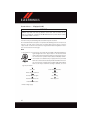
MANUAL TRANSMISSION 1 TO 4 SKIP SHIFT
Skip 1
Shift 2
3 5 R
6
Skip Shift is enabled when vehicle speed is greater than 16 mph
(26 km/h) but less than 18 mph (29 km/h) and the accelerator is at
20% or less.
For optimal fuel economy, under low acceleration conditions, your
vehicle will only allow you to shift from first gear to fourth gear. Additionally, the skip shift
message will appear in the tachometer.
ADDING FUEL
1. Press the fuel filler door release switch (located in the driver's door map pocket).
2. Open the fuel filler door.
3. There is no fuel filler cap. A flapper door inside the pipe seals the system.
4. Insert the fuel nozzle fully into the filler pipe – the nozzle opens and holds the flapper
door while refueling.
NOTE:
Only the correct size nozzle opens the latches allowing the flapper door to open.
5. Fill the vehicle with fuel – when the fuel nozzle “clicks” or shuts off the fuel tank is full.
37
O P E R AT I N G Y O U R V E H I C L E
6. Remove the fuel nozzle and close the fuel door.
NOTE:
A funnel is provided (located in the trunk in the spare tire area) to open the flapper
door to allow for emergency refueling with a gas can.
CAUTION!
To avoid fuel spillage and overfilling, do not “top off” the fuel tank after filling.
WARNING!
• Never have any smoking materials lit in or near the vehicle when the fuel door is
open or the tank is being filled.
• Never add fuel when the engine is running. This is in violation of most state and
federal fire regulations and may cause the “Malfunction Indicator Light” to turn on.
• A fire may result if fuel is pumped into a portable container that is inside of a vehicle.
You could be burned. Always place fuel containers on the ground while filling.
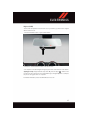
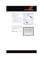
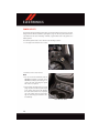
EMERGENCY FUEL FILLER DOOR RELEASE
If you are unable to open the fuel filler door, use the fuel filler door emergency release
procedure by following the proceeding steps:
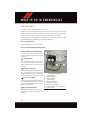
1. Open the liftgate.
2. Locate the carpet access door (on the right side inner trim panel of the trunk).
Carpet Access Door
38
O P E R AT I N G Y O U R V E H I C L E
3. Pull the edge of the access door on the right side inner trim panel to expose the
emergency release cable.
Opening Access Door
4. Pull the emergency release cable to release the fuel door.
5. Return the emergency release cable to
the original position (inside the inner
trim panel) and push the carpet back
into the original position.
Emergency Release Cable
39
O P E R AT I N G Y O U R V E H I C L E
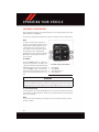
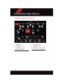
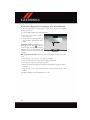
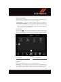
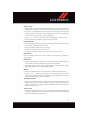
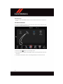
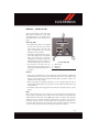
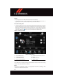
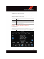
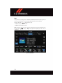
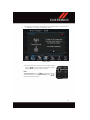
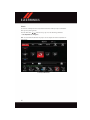
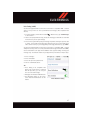
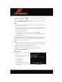
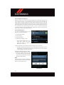
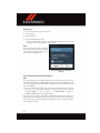
AUTOMATIC TEMPERATURE CONTROL (ATC)
Automatic Climate Controls Touchscreen
1 — MAX A/C Button
2 — A/C Button
3 — Air Recirculation Button
4 — AUTO Button
5 — Front Defroster Button
6 — Rear Defroster Button
40
7 — Mode Control Buttons
8 — Blower Control Buttons
9 — OFF Button
10 — Temperature Control Down Button
11 — Temperature Control Up Button
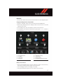
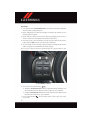
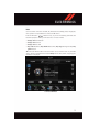
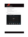
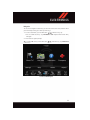
O P E R AT I N G Y O U R V E H I C L E
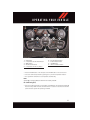
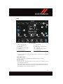
Climate Control Knobs
1 — A/C Button
2 — Temperature Control Down Button
3 — OFF Button
4 — Blower Control Knob
5 — Temperature Control Up Button
6 — Front Defroster Button
7 — Rear Defroster Button
8 — AUTO Button
9 — Air Recirculation Button
• Press the AUTO button on the faceplate or the AUTO button on the touchscreen.
• Select the desired temperature by pushing the up or down temperature buttons.
• The system will maintain the set temperature automatically.
NOTE:
At Wide Open Throttle (WOT) the A/C will momentarily shut Off.
Air Conditioning (A/C)
• If the air conditioning button is pressed while in AUTO mode, the system will exit AUTO
mode and stay in A/C. The mode and blower will be set at the closest mode and blower
position that the system was operating in AUTO.
41
O P E R AT I N G Y O U R V E H I C L E
Air Recirculation
/ Max A/C
• Rotate the Temperature Control to the MAX A/C position to automatically turn on both
Air Conditioning and Recirculation.
• For window defogging, turn the recirculation button off.
• Recirculation is not allowed in defrost/floor (mix) modes for approximately five
minutes. Recirculation is allowed in floor mode.
PARKVIEW REAR BACK UP CAMERA — IF EQUIPPED
Your vehicle may be equipped with the ParkView Rear Back Up Camera that allows you to
see an on-screen image of the rear surroundings of your vehicle whenever the shift
lever/gear selector is put into REVERSE. The ParkView camera is located on the rear of the
vehicle above the rear license plate. The image will be displayed in the touchscreen
display along with a caution note to “check entire surroundings” across the top of the
screen. After five seconds this note will disappear.
NOTE:
The ParkView Rear Back Up Camera has programmable modes of operation that may be
selected through the Uconnect System. Refer to “Uconnect Settings” in “Understanding
Your Instrument Panel” in the Owner’s Manual on the DVD for further information.
If your vehicle is equipped with the Camera Delay feature and it is turned ON, the rear
camera image will be displayed for up to 10 seconds when the vehicle is shifted out of
REVERSE unless the forward vehicle speed exceeds 8 mph (13 km/h), the transmission
is shifted into "PARK" or the vehicle's ignition is cycled to the OFF position.
When the Vehicle is shifted out of REVERSE (with camera delay turned OFF) the rear
camera mode is exited and the last touchscreen appears again.
The active guide lines are overlaid on the image to illustrate the width of the vehicle and
its projected backup path based on the steering wheel position.
Different colored zones indicate the distance to the rear of the vehicle.
Zone
Red
Yellow
Green
42
Distance to the rear of the vehicle
0 - 1 ft (0 - 30 cm)
1 ft - 6.5 ft (30 cm - 2 m)
6.5 ft or greater (2 m or greater)
O P E R AT I N G Y O U R V E H I C L E
WARNING!
Drivers must be careful when backing up even when using the ParkView Rear Back Up
Camera. Always check carefully behind your vehicle, and be sure to check for
pedestrians, animals, other vehicles, obstructions, or blind spots before backing up.
You are responsible for the safety of your surroundings and must continue to pay
attention while backing up. Failure to do so can result in serious injury or death.
CAUTION!
• To avoid vehicle damage, ParkView should only be used as a parking aid. The
ParkView camera is unable to view every obstacle or object in your drive path.
• To avoid vehicle damage, the vehicle must be driven slowly when using ParkView to
be able to stop in time when an obstacle is seen. It is recommended that the driver
look frequently over his/her shoulder when using ParkView.
NOTE:
If snow, ice, mud, or any foreign substance builds up on the camera lens, clean the lens,
rinse with water, and dry with a soft cloth. Do not cover the lens.
43
ELECTRONICS
YOUR VEHICLE'S SOUND SYSTEM
1. Uconnect Voice Command
2. Uconnect Phone
Button pg. 72
Button pg. 91
3. Steering Wheel Audio Controls (Left) pg. 100
4. Steering Wheel Audio Controls (Right) pg. 100
5. Volume Knob — Audio Mute Button
6. Screen Off Button
44
ELECTRONICS
7. Back Button
8. Tune/Scroll Knob — Browse/Enter Button
9. Uconnect 8.4 Radio pg. 46
10. Power Outlet
11. USB Port pg. 65
12. SD Card Slot pg. 65
13. Aux Jack pg. 65
45
ELECTRONICS
YOUR RADIO
Uconnect 8.4AN
• 8.4” Touchscreen
• Navigation with 3D City and Terrain
Modeling Standard
• HD Button will be visible on right side of
screen when viewing AM or FM (U.S.
Market Only)
• SiriusXM Travel Link feature listed
within Apps
Uconnect 8.4AN
UCONNECT ACCESS
Uconnect Access — If Equipped (U.S. Residents Only)
WARNING!
• ALWAYS obey traffic laws and pay attention to the road. Some Uconnect Access
services, including 9-1-1 and Assist, will NOT work without an operable 1X
(voice/data) or 3G (data) network connection.
• ALWAYS drive safely with your hands on the steering wheel. You have full responsibility and assume all risks related to the use of the Uconnect features and
applications in this vehicle. Only use Uconnect when it is safe to do so. Failure to
do so may result in an accident involving serious injury or death.
NOTE:
Your vehicle may be transmitting data as authorized by the subscriber.
Uconnect Access enhances your ownership and driving experience by connecting your
vehicle to an operable 1X (voice/data) or 3G (data) network. When connected to an
operable 1X (voice/data) or 3G (data) network, you can:
• Place a call to a local 9-1-1 Operator for emergency assistance.
• Remotely lock/unlock your doors and start your vehicle from virtually anywhere, using
the Uconnect Access App from your device. You can also do so by logging into Mopar
Owner Connect, or by calling Uconnect Care when your vehicle has an operable 1X
(voice/data) or 3G (data) network connection. Services can only be used where coverage
is available; see coverage map for details.
46
ELECTRONICS
• Turn your vehicle into a WiFi Hotspot and connect your devices to the internet.
• Receive text or email notifications if your vehicle's theft alarm goes off.
• Receive stolen vehicle assistance, using GPS technology to help authorities locate your
vehicle if it is stolen.
• Listen to your text messages or send free-form text messages with your voice while
keeping your hands on the wheel, using the Voice Texting feature. Requires a device
that supports Bluetooth Message Access Profile (MAP).
• Search for places to eat, shop, relax and play with Yelp, using your voice or on-screen
menu. Then navigate to them (navigation standard on Uconnect 8.4AN).
• Get operator assistance using the ASSIST button on your interior rearview mirror.
Before you drive, familiarize yourself with the easy-to-use Uconnect Access.
1. The ASSIST and 9-1-1 buttons are located on your rearview mirror. The ASSIST button
is used for contacting Roadside Assistance, Vehicle Care and Uconnect Care. The
9-1-1 button connects you to emergency services.
NOTE:
• Vehicles sold in Canada and Mexico DO NOT have 9-1-1 call system capabilities.
9-1-1 or other emergency line operators in Canada and Mexico may not answer or
respond to 9-1-1 system calls.
• Vehicles sold in Canada and Mexico DO NOT have Assist call system capabilities.
” button on the touchscreen. This is where you can begin
2. The Uconnect “Apps
your registration process, manage your Apps and purchase WiFi on demand.
3. The Uconnect Voice Command and Uconnect Phone buttons are located on the left
side of your steering wheel. These buttons let you use your voice to give commands,
make phone calls, send and receive text messages hands-free, enter navigation
destinations, and control your radio and media devices.
Included Trial Period For New Vehicles
Your new vehicle may come with an included trial period for use of the Uconnect Access
Services starting at the date of vehicle purchase (date based on vehicle sales notification
from your dealer). To activate the trial, you must first register with Uconnect Access. After
the trial period, if you wish to continue your Uconnect Access Services you can choose to
purchase a subscription.
Features And Packages
• After the trial period, you can subscribe to continue your service by visiting the
Uconnect Store located within the Mopar Owner Connect website
moparownerconnect.com. If you need assistance, U.S. residents can call Uconnect
Care at 1-855-792-4241 .
• For the latest information on packages and pricing information: U.S. residents visit
DriveUconnect.com.
47
ELECTRONICS
Uconnect Access Registration (U.S. 48 Contiguous States, Alaska And Hawaii)
To unlock the full potential of Uconnect Access in your vehicle, you first need to register
with Uconnect Access.
1. Push the ASSIST button on your rearview mirror.
2. Press the “Uconnect Care” button on
the touchscreen.
3. A helpful Uconnect Care Agent will register your vehicle and handle all of the
details.
Signing up is easy! Simply follow the steps
above. Or, press the “Apps
” button on
the touchscreen, then select the Uconnect
registration app to “Register By Web” and
complete the process using your device or
computer.
ASSIST Button
Why sign up for Uconnect Access? Here are just a few examples of things you’ll be able
to do:
• Know that help, if you need it, is only a button press away.
• Lock and unlock your vehicle doors from hundreds of miles away.
• Discover great, new places around you using Yelp.
• Dictate and send text messages by speaking out loud (all while keeping both hands on
the wheel!)
• Enjoy the best in music and entertainment from around the world with apps like
Pandora.
For further information please visit DriveUconnect.com.
48
ELECTRONICS
Download The Uconnect Access App
You’re only a few steps away from using remote commands and playing your favorite music
in your vehicle.
To link your internet radio accounts:
1. Download the Uconnect Access App on your device.
Mobile App
2. Press the Via Mobile icon on the navigation bar at the bottom of
the app.
3. Press the app you’d like to connect to your vehicle.
4. Enter your login information for the selected app and press
Link.
5. Next time you’re in your vehicle, enable Bluetooth, pair your
device and select the Via Mobile app you want to play from the
Uconnect touchscreen to stream your personalized music.
NOTE:
• You can also complete this process on the web. Simply visit
moparownerconnect.com log in and click Set Up Via Mobile Profile (under Quick
Links).
• Once you download the app to your compatible device, you will also be able to
lock/unlock its doors from virtually anywhere.
49
ELECTRONICS
Via Mobile Apps — If Equipped
• Aha by HARMAN — Aha by HARMAN makes it easy to instantly access your favorite
Web content on the go. Choose from over 40,000+ stations spanning internet radio,
personalized music, news, entertainment, hotels, weather, audiobooks, Facebook,
Twitter, and more.
• iHeartRadio — iHeartRadio provides instant access to more than 1,500 live radio
stations from across the country and allows listeners to create custom music stations
inspired by their favorite artists or songs.
• Pandora — Pandora gives people the music and comedy they love anytime, anywhere.
Personalized stations launch instantly, with the input of a favorite artist, track,
comedian, or genre.
• Slacker Radio — Enjoy millions of songs and hundreds of handcrafted stations.
NOTE:
For detailed information on how to use Via Mobile apps visit the
Mopar Owner Connect website (moparownerconnect.com) and log
in using the username and password you set up when registering
for Uconnect Access.
Via Mobile
Renewing Subscriptions And Purchasing WiFi Hotspot (U.S. 48 Contiguous
States, Alaska And Hawaii)
Subscriptions, and WiFi Hotspot, can be purchased from the Uconnect Store within your
vehicle, and online at Mopar Owner Connect. If you need help push the ASSIST button on
the rearview mirror, then select Uconnect Care (or dial 1-855-792-4241 ).
NOTE:
You must set up a Uconnect Access Payment Account online (log in to
moparownerconnect.com, go to Edit Profile, then Uconnect Payment Account, to set up
and manage your Payment Account).
50
ELECTRONICS
Getting Started With Apps
Applications (Apps for short) in your Uconnect Access system are designed to deliver the
features and services that you want. There are two basic categories:
1. Built-In Features — use the 1X (voice/data) or 3G (data) network on your 8.4AN radio.
2. Uconnect Access Via Mobile — use the Uconnect Access App and your device's data
plan to access your personal Pandora, iHeartRadio, Aha and Slacker accounts from the
vehicle and control them using the touchscreen. Customer's data plan charges will
apply. Available on Uconnect 8.4AN Radios.
Apps Main Menu
Press the “Apps
” button on the touchscreen to open the Apps main menu, in this
screen you will be able to access all of your available Apps. To access an App directly,
press the corresponding button on the touchscreen and you will be directed to that App.
To view the rest our your Apps, press the page forward or page back button.
Uconnect Apps
1 — Apps Button
2 — Page Back Button
App Manager
Press the “App Manager” button to access the following categories:
Favorite Apps — This is the default screen when you first press the “App Manager” button
on the touchscreen, and is a good place to put the apps you use most frequently. To make an
App a “favorite”, press the “Settings” button on the touchscreen to the right of the App.
51
ELECTRONICS
All Apps — All of your available Apps will reside in the “All Apps” folder.
Running Apps — Press this tab to see which apps are currently running.
Maintaining Your Uconnect Access Account
Selling Your Vehicle
When you sell your vehicle, we recommend that you remove your Uconnect Access
Account information from the vehicle. You can do this on the Mopar Owner Connect
website (moparownerconnect.com). Removing your account information cancels your
subscription and makes your vehicle factory-ready for a new owner/subscriber.
For additional information on Uconnect:
• U.S. residents - visit DriveUconnect.com or call 1-877-855-8400 (24 hours a day 7
days a week).
• Canadian Residents - visit DriveUconnect.ca or call, 1-800-465-2001 (English) or
1-800-387-9983 (French).
Mon. – Fri., 8:00 am – 8:00 pm, ET
Sat., 9:00 am – 5:00 pm, ET
Sun., Closed
52
ELECTRONICS
Built-In Features
WARNING!
• ALWAYS obey traffic laws and pay attention to the road. Some Uconnect Access
services, including 9-1-1 and Assist, will NOT work without an operable 1X
(voice/data) or 3G (data) network connection.
• ALWAYS drive safely with your hands on the steering wheel. You have full responsibility and assume all risks related to the use of the Uconnect features and
applications in this vehicle. Only use Uconnect when it is safe to do so. Failure to
do so may result in an accident involving serious injury or death.
• Ignoring the rearview mirror light could mean you may not have 9-1-1 Call service
if needed. If the rearview mirror light is illuminated, have an authorized dealer
service the 9-1-1 Call system immediately.
• The Occupant Restraint Controller (ORC) turns on the Air Bag Warning Light on the
instrument panel if a malfunction is detected in any part of the airbag system. If the
Air Bag Warning Light is illuminated, the air bag system may not be working
properly and the 9-1-1 system may not to send a signal to a 9-1-1 operator if an air
bag is deployed. If the Air Bag Warning Light is illuminated, have an authorized
dealer service your vehicle immediately.
• If anyone in the vehicle could be in danger (e.g., fire or smoke is visible, dangerous
road conditions or location), do not wait for voice contact from a 9-1-1 operator. All
occupants should exit the vehicle immediately and move to a safe location.
• The 9-1-1 Call system is embedded into the vehicle’s electrical system. Do not add
aftermarket electrical equipment to the vehicle’s electrical system. This may
prevent your vehicle from sending a signal to initiate an emergency call. To avoid
interference that can cause the 9-1-1 Call system to fail, never add aftermarket
equipment (e.g., two-way mobile radio, CB radio, data recorder, etc.) to your
vehicle’s electrical system or modify the antennas on your vehicle.
• IF YOUR VEHICLE LOSES BATTERY POWER FOR ANY REASON (INCLUDING
DURING OR AFTER AN ACCIDENT), the Uconnect features, apps and services,
among others, will not operate.
NOTE:
Your vehicle may be transmitting data as authorized by the subscriber.
53
ELECTRONICS
1. Assist Call (8.4AN) — The rearview mirror contains an ASSIST push button which
automatically connects the vehicle occupants to one of these predefined destinations
for immediate support:
• Roadside Assistance Call — If you
get a flat tire, or need a tow, you’ll be
connected to someone who can help
anytime. Additional fees may apply.
Additional information in this section.
• Uconnect Access Care — In vehicle
support for Uconnect Access System,
Apps and Features.
• Vehicle Care — Total support for your
FCA US LLC vehicle.
ASSIST/9-1-1 Buttons
1 — ASSIST Button
2. Emergency 9-1-1 Call (If Equipped) —
2 — 9-1-1 Button
The rearview mirror contains a 9-1-1
button that, when pressed, may place a
call from your vehicle to a local 9-1-1
operator to request help from local police, fire or ambulance personnel. If this button
is accidentally pressed, you will have 10 seconds to stop the call. To cancel, press the
9-1-1 Call button again or press the “Cancel” button shown on the touchscreen. After
10 seconds has passed, the 9-1-1 call will be placed and only the 9-1-1 operator can
cancel it. The LED light on the rearview mirror will turn green once a connection to a
9-1-1 operator has been made. The green LED light will turn off once the 9-1-1 call is
terminated. Have an authorized dealer service the vehicle if the rearview mirror light is
continuously red. On equipped vehicles, this feature requires a functioning electrical
system and an operable 1X (voice/data) or 3G (data) network connection to function
properly. If a connection is made between a 9-1-1 operator and your vehicle, you
understand and agree that 9-1-1 operators may, like any other 9-1-1 call, record
conversations and sounds in and near your vehicle upon connection.
3. Roadside Assistance (If Equipped) — If your vehicle is equipped with this feature and
has an operable 1X (voice/data) or 3G (data) network connection, you may be able to
connect with Roadside Assistance by pressing the "ASSIST" button on the rearview
mirror. You will be presented with Assist Care options. Make a selection by pressing the
prompts displayed on the radio. If Roadside Assistance is provided to your vehicle, you
agree to be responsible for any additional roadside assistance service costs that you
may incur. In order to provide Uconnect Services to you, we may record and monitor
your conversations with Roadside Assistance, Uconnect Care or Vehicle Care, whether
such conversations are initiated through the Uconnect Services in your vehicle, your
device or via a landline device, and may share information obtained through such
recording and monitoring in accordance with regulatory requirements. You acknowledge, agree and consent to any recording, monitoring or sharing of information
obtained through any such call recordings.
54
ELECTRONICS
4. Yelp — Customers have the ability to search for nearby destinations or a point of
interest (POI) either by category or custom search by using keywords (for example,
“Italian restaurant”). Searching can be done by either voice or by using the touchscreen keypad. Using the touchscreen, launch Yelp by selecting the “Apps” icon.
Press the “All Apps” tab, and then press “Yelp.” To use voice recognition, push the VR
button on the steering wheel and say “launch Yelp,” then follow the instructions on the
Teleprompter.
5. Security Alarm Notification — The Security Alarm Notification feature notifies you via
email or text (SMS) message when the vehicle’s factory-installed security alarm system
has been set-off. There are a number of reasons why your alarm may have been
triggered, one of which could be that your vehicle was stolen. If so, please see the
details of the Stolen Vehicle Assistance service below. When you register, Security
Alarm Notification is automatically set to send you an email at the mail address you
provide should the alarm go off. You may also opt to have a text message sent to your
device.
6. Stolen Vehicle Assistance — If your vehicle is stolen, contact local law enforcement
immediately to file a stolen vehicle report. Once this report has been filed, Uconnect
care can help locate your vehicle. The Uconnect Care agent will ask for the stolen
vehicle report number issued by local law enforcement. Then, using GPS technology
and the built-in wireless connection within your vehicle, the Uconnect Care agent will
be able to locate the stolen vehicle and work with law enforcement to help recover it.
Your vehicle must be within the United States, have network coverage and must be
registered with Uconnect Access with an active subscription that includes the
applicable feature.
7. WiFi Hotspot — WiFi Hotspot is an in-vehicle feature that connects your device to an
operable 1X (voice/data) or 3G (data) network using Uconnect Access and is ready to
go where ever you are. Once your vehicle is registered for Uconnect Access, you can
purchase a Wifi Hotspot subscription at the Uconnect Store. After you've made your
purchase, turn on your signal and connect your passengers devices. It's never been
easier to bring your home or office with you.
WARNING!
NEVER use the WiFi Hotspot when you are driving the vehicle. As the driver, you should
only use the WiFi Hotspot when the vehicle is parked in a safe location. Failure to do so
may result in an accident involving serious injury or death.
NOTE:
Your vehicle must have a working electrical system for any of the in vehicle Uconnect
features to operate.
55
ELECTRONICS
Uconnect Access Remote Features
If you own a compatible iPhone or Android powered device, the Uconnect Access App
allows you to remotely lock or unlock your doors or activate your horn and lights from
virtually anywhere. Your vehicle must have an operable 1X (voice/data) or 3G (data)
network connection). Services can only be used where coverage is available; see coverage
map for details. You can download the App from Mopar Owner Connect or from the App
Store (iPhone) or Google Play store. Visit UconnectPhone.com to determine if your device
is compatible. For Uconnect Phone customer support and to determine if your device is
compatible.
U.S. residents - visit UconnectPhone.com or call 1-877-855-8400
Remote Door Lock/Unlock — This feature provides the ability to lock or unlock the door on
your vehicle, without the keys and from virtually any distance. You can send a request to
your vehicle in one of three ways:
1. Using the Uconnect Access App from a compatible device.
2. From the Mopar Owner Connect website.
3. By contacting the Uconnect Care on the phone.
To use this feature after the Uconnect Access App is downloaded, login using your user
name and password. You will need your four digit Uconnect Security PIN to confirm the
request. Press the “closed lock” icon on your Uconnect Access App to lock the doors, and
press the “open Lock” icon to unlock the driver’s door.
You can set-up notifications for your account to receive an email or text (SMS) message
every time a command is sent. Login to Mopar Owner Connect (moparownerconnect.com)
and click on Edit Profile to manage Uconnect Notifications.
Remote Horn And Lights — It’s easy to locate a vehicle in a dark, crowded or noisy parking
area by activating the horn and lights. It may also help if you need to draw attention to your
vehicle for any reason. You can send a request to your vehicle in one of three ways:
1. Using the Uconnect Access App from a compatible device.
2. From the Mopar Owner Connect website.
3. By contacting the Uconnect Care on the phone.
To use this feature after the Uconnect Access App is downloaded, login using your user
name and password. You will need your four digit Uconnect Security PIN to confirm the
request. You can set-up notifications for your account to receive an email or text (SMS)
message every time a command is sent. Login to Mopar Owner Connect
(moparownerconnect.com) and click on Edit Profile to manage Uconnect Notifications.
Voice Texting — Want to dictate a personal message? Register with Uconnect Access to
take advantage of a new, cloudbased Voice Texting service, an enhancement to Voice Text
Reply.
56
ELECTRONICS
Voice Texting allows you to compose a new text or reply to an incoming text message.
Before you attempt to use the Voice Texting feature, check to ensure you have the
following:
1. A paired, Bluetooth enabled device with the Message Access Profile (MAP). Not all
Bluetooth enabled devices support MAP, including all iPhones (Apple iOS). Visit
UconnectPhone.com for system and device compatibility information.
2. An active Uconnect Access trial or paid subscription. Press the “Apps
the touchscreen to begin the registration process.
” button on
3. Accept the “Allow MAP” profile request on your device. (Please refer to device
manufacturer instructions for details).
To Send A Text Message:
1. Push the Uconnect Phone Button
on the steering wheel.
2. Wait for the beep.
3. Say “Text.”
4. Uconnect will prompt you “Say the phone number, or full name and phone type of the
contact you want to send a message to.”
5. Wait for the beep and say a contact that is in your phonebook, or a mobile phone
number that you would like to send the message to.
6. Uconnect will prompt you “Please say the message that you would like to send.” (If you
do not hear this prompt, you may not have an active subscription with Uconnect Access).
7. Wait for the beep, and then dictate any message up to 140 characters. If you exceed
140 characters, you will hear the following prompt: “Message was too long; your
message will be truncated.”
8. Uconnect will then repeat the message back to you.
9. Uconnect will prompt you: “To add to your message, say “Continue”; To delete the
current message and start over, say “Start Over”; to send the current message, say
“Send”; to hear the message again, say “Repeat”.
10. If you are happy with your message and would like to send it, wait for the beep and
say “Send”.
11. Uconnect will then say “Sending your message.”
Sample Commands For Voice Text Reply And Voice Texting
Example Command
“Text John Smith”
“Text 123 456 7890”
“Show messages”
Action
Send a message to specific contact in
address book
Send 123 456 7890 a message from your
phonebook
See recent text messages listed by number
on Uconnect screen
57
ELECTRONICS
Example Command
“Listen to/view (message number four, for
example)”
“Reply”
Action
Hear messages or read it on Uconnect
screen
Send a voice text reply to a current message
Forward current text to specific contact in
“Forward text/message to “John Smith”
address book
Forward current text to specific phone
“Forward text/message to “123 456 7890”
number
UCONNECT 8.4AN
Uconnect 8.4AN AT A GLANCE
Uconnect 8.4AN Radio Screen
CAUTION!
Do NOT attach any object to the touchscreen, doing so can result in damage to the
screen.
58
ELECTRONICS
Setting The Time
• Model 8.4AN synchronizes time automatically via GPS, so it should not require any
time adjustment. If you do need to set the time manually, follow the instructions below.
• If the time is not displayed at the top of the screen, press the “Apps” button then the
“Settings” button on the touchscreen. In the Settings screen, press the “Clock” button
on the touchscreen, then check or uncheck this option.
• Press “+” or “–” next to Set Time Hours and Set Time Minutes to adjust the time.
• If these features are not available, uncheck the Sync Time box.
Background Themes
• Screen background themes are selectable from a pre-loaded list of themes. If you’d like
to set a theme, follow the instructions below.
• Press the “Settings” button on the touchscreen.
• Press the “Display” button on the touchscreen.
• Then press “Set Theme” button on the touchscreen and select a theme.
Audio Settings
Press the “Settings” button, then “Audio” button on the touchscreen to Adjust the
settings below:
Balance/Fade
• Press the “Balance/Fade” button on the touchscreen to Balance audio between the
front speakers or fade the audio between the rear and front speakers.
• Pressing the “Front,” “Rear,” “Left,” or “Right” buttons on the touchscreen or press
and drag the Speaker Icon to adjust the Balance/Fade.
Equalizer
• Press the “Equalizer” button on the touchscreen to activate the Equalizer screen.
• Press the “+” or “–” buttons on the touchscreen, or press and drag over the level bar
for each of the equalizer bands. The level value, which spans between plus or minus 9,
is displayed at the bottom of each of the Bands.
Speed Adjusted Volume
• Press the “Speed Adjusted Volume” button on the touchscreen to activate the Speed
Adjusted Volume screen. The Speed Adjusted Volume is adjusted by pressing the
volume level indicator. This alters the automatic adjustment of the audio volume with
variation to vehicle speed.
Surround Sound
• Press the “Surround Sound” button on the touchscreen, select On or Off followed by
pressing the “arrow back” button on the touchscreen. When this feature is activated, it
provides simulated surround sound mode.
59
ELECTRONICS
Aux Volume Offset
• Press the “Aux Volume Offset” button on the touchscreen and choose a level from –3
to +3.
PERSONALIZED MENU BAR
The Uconnect features and services in the main menu bar are easily changed for your
convenience. Simply follow these steps:
Uconnect 8.4AN Main Menu
1. Press the “Apps
” button to open the App screen.
2. Press and hold, then drag the selected App to replace an existing shortcut in the main
menu bar.
3. The replaced shortcut will now be an active App/shortcut on the main menu bar.
60
ELECTRONICS
RADIO
Uconnect 8.4AN Radio
1 — Radio Station Presets
2 — Toggle Between Presets
3 — Status Bar
4 — View Small Navigation Map
5 — HD Radio
6 — Main Category Bar
7 — Audio Settings
8 — Seek Up
9 — Direct Tune To A Radio Station
10 — Seek Down
11 — Browse And Manage Presets
12 — Radio Bands
• To access the Radio mode, press the “Radio” button on the touchscreen at the lower
left of the screen.
Selecting Radio Stations
• Press the desired radio band (AM, FM or SXM) button on the touchscreen.
Seek Up/Seek Down
• Press the Seek up or down arrow buttons on the touchscreen for less than two seconds
to seek through radio stations.
• Press and hold either arrow button on the touchscreen for more than two seconds to
bypass stations without stopping. The radio will stop at the next listenable station once
the arrow button on the touchscreen is released.
61
ELECTRONICS
Direct Tune
• Tune directly to a radio station by pressing the “Tune” button on the screen, and
entering the desired station number.
Store Radio Presets Manually
Your radio can store 36 total preset stations, 12 presets per band (AM, FM and SXM). They
are shown at the top of your radio screen. To see the 12 preset stations per band, press the
arrow button on the touchscreen at the top right of the screen to toggle between the two
sets of six presets.
To store a radio preset manually, follow the steps below:
1. Tune to the desired station.
2. Press and hold the desired numbered button on the touchscreen for more than two
seconds or until you hear a confirmation beep.
HD Radio
• HD Radio operates similar to conventional radio except it allows broadcasters to
transmit a high-quality digital signal.
• With an HD radio receiver, the listener is provided with a clear sound that enhances the
listening experience. HD radio can also transmit data such as song title or artist.
SiriusXM PREMIER OVER 160 CHANNELS
Get every channel available on your satellite radio, and enjoy all you want, all in one place.
Hear commercial-free music plus sports, news, talk and entertainment. Get all the
premium programming, including Howard Stern, every NFL game, Oprah Radio, every
MLB and NHL game, every NASCAR race, Martha Stewart and more. And get 20+ extra
channels, including SiriusXM Latino, offering 20 channels of commercial free music,
news, talk, comedy, sports and more dedicated to Spanish language programming.
• To access SiriusXM Satellite Radio, press the “SXM” button on the touchscreen on the
main Radio screen.
The following describes features that are available when in SiriusXM Satellite Radio
mode:
Seek Up/Seek Down
• Press the Seek arrow buttons on the touchscreen for less than two seconds to seek
through channels in SXM mode.
• Press and hold either arrow button on the touchscreen for more than two seconds to
bypass channels without stopping. The radio will stop at the next listenable channel
once the arrow button on the touchscreen is released.
Direct Tune
• Tune directly to a SXM channel by pressing the “Tune” button on the touchscreen on
the screen, and entering the desired station number.
62
ELECTRONICS
Jump
• Automatically tells you when Traffic & Weather for a favorite city is available, and gives
you the option to switch to that channel. Press “Jump” to activate the feature. After
listening to Traffic and Weather, press “Jump” again to return to the previous channel.
Fav
• Activates the favorites menu. You can add up to 50 favorite artists or songs. Just press
“Add Fav Artist” or “Add Fav Song” while the song is playing. You will then be alerted
any time one of these songs, or works by these artists, is playing on other SiriusXM
channels.
SiriusXM Parental Controls
• You can skip or hide certain channels from view if you do not want access to them.
Press the “Apps” button on the touchscreen, then the “Settings” button on the
touchscreen, next press the “Sirius Setup” button on the touchscreen, then select
Channel Skip. Press the box check-mark next to the channel you want skipped. They
will not show up in normal usage.
• SiriusXM also offers the option to permanently block selected channels. Call
(1-888-601-6297 for U.S. customers, 1-877-438-9677 for Canadian customers) and
request the Family-Friendly Package.
Browse
Lets you browse the SiriusXM channel listing or Genre listing. Favorites, Game Zone,
Weather and Jump settings also provide a way to browse the SiriusXM channel list.
Browse
Sub-Menu
All
Genre
Presets
Favorites
Game Zone
Jump
Sub-Menu Description
Shows the channel listing.
Provides a list of all genres, and lets you jump to a channel within the selected
genre.
Lets you scroll the list of Preset satellite channels. Press the channel, or press
Enter on the Tune knob, to go to that channel. Press the trash can icon to
delete a preset. Your presets are also shown at the top of the main Satellite
Radio screen.
Lets you manage artists and songs in the Favorites list and configure Alert
Settings to let you know when favorite songs or artists are playing on other
channels. Also, view a list of channels airing any of your Favorites.
Provides alerts when your favorite sports teams are starting a game which is
being aired on other SiriusXM channels, or when their game score is announced. You can select and manage your Teams list here, and configure
alerts.
Lets you select your favorite cities for Traffic & Weather information, which is
used by the Jump feature on the main satellite radio screen.
63
ELECTRONICS
Replay
Lets you replay up to 44 minutes of the content of the current SiriusXM channel.
Replay Option Option Description
Play/Pause
Press to Pause content playback. Press Pause/Play again to resume playback.
Rewind/RW Rewinds the channel content in steps of five seconds. Press and hold to
rewind continuously, then release to begin playing content at that point.
Fast
Forwards the content, and works similarly to Rewind/RW. However, Fast
Forward/FW Forward/FW can only be used when content has been previously rewound.
Replay Time Displays the amount of time in the upper center of the screen by which your
content lags the Live channel.
Live
Resumes playback of Live content at any time while replaying rewound
content.
• SiriusXM services require subscriptions, sold separately after the 12-month trial
included with the new vehicle purchase. If you decide to continue your service at the
end of your trial subscription, the plan you choose will automatically renew and bill at
then-current rates until you call SiriusXM at 1-866-635-2349 for U.S. residents and
1-888-539-7474 for Canadian residents to cancel. See SiriusXM Customer Agreement
for complete terms at www.siriusxm.com (US residents) or siriusxm.ca (Canadian
residents). All fees and programming subject to change. Our satellite service is
available only to those at least 18 and older in the 48 contiguous USA and D.C. Our
Sirius satellite service is also available in PR (with coverage limitations). Our Internet
radio service is available throughout our satellite service area and in AK and HI. ©2015
Sirius XM Radio Inc. Sirius, XM and all related marks and logos are trademarks of Sirius
XM Radio Inc.
64
ELECTRONICS
MEDIA HUB — USB/MP3/SD CARD
There are many ways to play music from
MP3 players, USB devices, or SD Cards
through your vehicle's sound system. Press
your Media button on the touchscreen to
begin.
Audio Jack (AUX)
• The AUX allows a device to be plugged
into the radio and utilize the vehicle’s
sound system, using a 3.5 mm audio
cable, to amplify the source and play
through the vehicle speakers.
• Pressing the “AUX” button on the touchscreen will change the mode to auxiliary
device if the audio jack is connected,
allowing the music from your device to be
heard through the vehicle's speakers. To
activate the AUX, plug in the audio jack.
• The functions of the device are controlled using the device buttons. The volume may be controlled using the radio or
the device.
Uconnect Media Hub
1 — SD Card Slot
2 — AUX Jack
3 — USB Port
USB Port
• Connect your compatible device using a USB cable into the USB Port. USB Memory
sticks with audio files can also be used. Audio from the device can be played on the
vehicles sound system while providing metadata (artist, track title, album, etc.)
information on the radio display.
• When connected, the compatible USB device can be controlled using the radio or
Steering Wheel Audio Controls to play, skip to the next or previous track, browse, and
list the contents.
• The battery charges when plugged into the USB port (if supported by the specific
device).
NOTE:
When connecting your device for the first time, the system may take several minutes to
read your music, depending on the number of files. For example, the system will take
approximately five minutes for every 1,000 songs loaded on the device. Also during the
reading process, the Shuffle and Browse functions will be disabled. This process is
needed to ensure the full use of your features and only happens the first time it is
connected. After the first time, the reading process of your device will take considerably
less time unless changes are made or new songs are added to the playlist.
65
ELECTRONICS
SD Card
• Play songs stored on an SD card inserted into the SD card slot.
• Song playback can be controlled using the radio or Steering Wheel Audio Controls to
play, skip to the next or previous track, browse, and list the contents.
Bluetooth Streaming Audio
• If equipped with Uconnect Voice Command, your Bluetooth-equipped device may also
be able to stream music to your vehicle's sound system. Your connected device must be
Bluetooth-compatible and paired with your system (see Uconnect Phone for pairing
instructions). You can access the music from your connected Bluetooth device by
button on the touchscreen while in Media mode.
pressing the Bluetooth
USB/SD Card/AUX CONTROLS
USB/SD Card/AUX Controls
1 — Repeat Music Track
2 — Music Track And Time
3 — Shuffle Music Tracks
4 — Music Track Information
5 — Show Songs Currently In Cue To
Be Played
6 — Browse Music By
7 — Music Source
The controls are accessed by pressing the desired button on the touchscreen and choosing
between AUX, USB, Bluetooth or SD Card.
NOTE:
Uconnect will automatically switch to the appropriate mode when something is first
connected or inserted into the system.
66
ELECTRONICS
NAVIGATION
• Press the “Nav” button on the touchscreen in the menu bar to access the Navigation system.
Changing The Navigation Voice Prompt Volume
1. Press the “View Map” button on the touchscreen from the Nav Main Menu.
2. With the map displayed, press the “Settings” button on the touchscreen in the lower
right area of the screen.
3. In the Settings menu, press the “Guidance” button on the touchscreen.
4. In the Guidance menu, adjust the Nav Volume by pressing the “+” or “–” buttons on
the touchscreen.
Uconnect 8.4AN Navigation
1 — Find A Destination
2 — View Map
3 — Information
4 — Emergency
5 — Navigation Settings
6 — Stop A Route
7 — Detour A Route
8 — Repeat Route Guidance Prompt
Finding Points Of Interest
• From the main Navigation menu, press the “Where To?” button on the touchscreen,
then press the “Points of Interest” button on the touchscreen.
• Select a Category and then a subcategory, if necessary.
• Select your destination and press the “Yes” button on the touchscreen.
67
ELECTRONICS
Finding A Place By Spelling The Name
• From the Main Navigation Menu press the “Where to?” button on the touchscreen,
press the “Points of Interest” button on the touchscreen, then press the “Spell Name”
button on the touchscreen.
• Enter the name of your destination.
• Press the “List” button on the touchscreen.
• Select your destination and press the “Yes” button on the touchscreen.
One-Step Voice Destination Entry
• Enter a navigation destination without taking your hands off the wheel.
button on the steering wheel, wait for
• Just press the Uconnect Voice Command
the beep and say something like, "Find Address 800 Chrysler Drive Auburn Hills MI."
NOTE:
Destination entry is not available while your vehicle is in motion. However, you can also
use Voice Commands to enter an address while moving. Refer to Common Navigation
Voice Commands in the Uconnect Voice Command section.
Setting Your Home Location
• Press the “Nav” button on the touchscreen in the menu bar to access the Navigation
system and the Main Navigation menu.
• Press the “Where To?” button on the touchscreen, then press the “Go Home” button on
the touchscreen.
• You may enter your address directly, use your current location as your home address, or
choose from recently found locations.
• To delete your Home location (or other saved locations) so you can save a new Home
location, press the “Where To?” button on the touchscreen from the Main Navigation
menu, then press the “Go Home” button on the touchscreen, and in the Yes screen
press the “Options” button on the touchscreen. In the Options menu press the “Clear
Home” button on the touchscreen. Set a new Home location by following the previous
instructions.
68
ELECTRONICS
Go Home
A Home location must be saved in the system.
• From the Main Navigation menu, press the “Where To?” button on the touchscreen,
then press the “Go Home” button on the touchscreen.
Uconnect 8.4AN Map
1 — Distance To Next Turn
2 — Next Turn Street
3 — Estimated Time Of Arrival
4 — Zoom In And Out
5 — Your Location On The Map
6 — Navigation Main Menu
7 — Current Street Location
8 — Navigation Routing Options
Your route is marked with a blue line on the map. If you depart from the original route, your
route is recalculated. A speed limit icon could appear as you travel on major roadways.
Adding A Stop
To add a stop you must be navigating a route.
• Press the “Menu” button on the touchscreen to return to the Main Navigation menu.
• Press the “Where To?” button on the touchscreen, then search for the extra stop. When
another location has been selected, you can choose to cancel your previous route, add
as the first destination or add as the last destination.
• Press the desired selection and press the “Yes” button on the touchscreen.
69
ELECTRONICS
Taking A Detour
To take a detour you must be navigating a route.
• Press the “Detour” button on the touchscreen.
NOTE:
If the route you are currently taking is the only reasonable option, the device may not
calculate a detour. For more information, see your Uconnect User's Manual.
SiriusXM TRAFFIC (US Market Only)
Don't Drive Through Traffic. Drive Around It.
Avoid congestion before you reach it. By enhancing your vehicle's navigation system with
the ability to see detailed traffic information, you can pinpoint traffic incidents, determine
average traffic speed and estimate travel time along your route. Since the service is
integrated with a vehicle's navigation system, SiriusXM Traffic can help drivers pick the
fastest route based on traffic conditions.
• Detailed information on traffic speed, accidents, construction, and road closings.
• Traffic information from multiple sources, including police and emergency services,
cameras and road sensors.
• Coast-to-coast delivery of traffic information.
• View conditions for points along your route and beyond. Available in over 130 markets.
SiriusXM Travel Link (US Market Only)
In addition to delivering over 130 channels of the best sports, entertainment, talk, and
commercial-free music, SiriusXM offers premium data services that work in conjunction
with compatible navigation systems. SiriusXM Travel Link brings a wealth of useful
information into your vehicle and right to your fingertips.
• Fuel Prices — Check local gas and diesel prices in your area and route to the station of
your choice.
• Movie Listings — Check local movie theatres and listings in your area and route to the
theater of your choice.
• Sports Scores — In-game and final scores as well as weekly schedules.
• Weather — Check variety of local and national weather information from radar maps to
current and 5-day forecast.
SiriusXM Travel Link feature is completely integrated into your vehicle. A few minutes
after you start your vehicle, Travel Link information arrives and updates in the background.
You can access the information whenever you like, with no waiting.
70
ELECTRONICS
To access SiriusXM Travel Link, press “Apps” button on the touchscreen, then press the
“SiriusXM Travel Link” button on the touchscreen.
NOTE:
SiriusXM Travel Link requires a subscription, sold separately after the five (5) year trial
subscription included with your vehicle purchase.
SiriusXM Travel Link is only available in the United States.
Fuel Prices
Movie Listings
Sports Scores
Weather
Check local gas and diesel prices in your area and route to the station of
your choice.
Check local movie theatres and listings in your area and route to the
theater of your choice.
In-game and final scores as well as weekly schedules.
Check variety of local and national weather information from radar maps
to current and 5-day forecast.
UCONNECT 8.4AN VOICE RECOGNITION QUICK TIPS
Introducing Uconnect
Start using Uconnect Voice Recognition with these helpful quick tips. It provides the key
Voice Commands and tips you need to know to control your Uconnect 8.4AN system.
You will see the
icon on your touchscreen with your Uconnect system.
Uconnect 8.4AN
71
ELECTRONICS
Get Started
1. U.S. residents can visit UconnectPhone.com to check device and feature compatibility
and to find device pairing instructions.
2. Reduce background noise. Wind and passenger conversations are examples of noise
that may impact recognition.
3. Speak clearly at a normal pace and volume while facing straight ahead. The microphone is positioned on the rearview mirror and aimed at the driver.
4. Each time you give a Voice Command, you must first push either the VR or Phone
button, wait until after the beep, then say your Voice Command.
5. You can interrupt the help message or system prompts by pushing the VR or Phone
button and saying a Voice Command from current category.
All you need to control your Uconnect system with your voice are the buttons on your
steering wheel.
Uconnect® VR/Phone Buttons
1. Uconnect Voice Recognition Button
a. Short Press: Push and release VR button to begin Radio, Climate, Navigation, and
other embedded functions. After you hear the single beep, say a command.
b. Long Press: Push and hold VR button then release for Siri functions. After you hear
the familiar Siri "double beep," say a command.
2. Uconnect Phone Button
receive a text
72
, Push to initiate, answer, or end a phone call, send or
ELECTRONICS
Basic Voice Commands
The basic Voice Commands below can be given at any point while using your Uconnect
system.
Push the VR button
. After the beep, say:
• Cancel to stop a current voice session
• Help to hear a list of suggested Voice Commands
• Repeat to listen to the system prompts again
Notice the visual cues that inform you of your voice recognition system’s status. Cues
appear on the touchscreen.
Uconnect 8.4AN
73
ELECTRONICS
Radio
Use your voice to quickly get to the AM, FM or SiriusXM Satellite Radio stations you would
like to hear. (Subscription or included SiriusXM Satellite Radio trial required.)
Push the VR button
. After the beep, say:
• Tune to ninety-five-point-five FM
• Tune to Satellite Channel Hits 1
TIP: At any time, if you are not sure of what to say or want to learn a Voice Command, push
the VR button
and say “Help.” The system will provide you with a list of
commands.
Uconnect 8.4AN Radio
74
ELECTRONICS
Media
Uconnect offers connections via USB, SD, Bluetooth and auxiliary ports (If Equipped).
Voice operation is only available for connected USB devices.
Push the VR button
. After the beep, say one of the following commands and
follow the prompts to switch your media source or choose an artist.
• Change source to Bluetooth
• Change source to iPod
• Change source to USB
• Play artist Beethoven; Play album Greatest Hits; Play song Moonlight Sonata; Play
genre Classical
TIP: Press the Browse button on the touchscreen to see all of the music on your USB
device. Your Voice Command must match exactly how the artist, album, song and genre
information is displayed.
Uconnect 8.4AN Media
75
ELECTRONICS
Phone
Making and answering hands-free phone calls is easy with Uconnect. When the Phonebook button is illuminated on your touchscreen, your system is ready.
U.S. residents can visit:
• UconnectPhone.com for device compatibility and pairing instructions.
Canadian residents can visit:
• UconnectPhone.com for mobile phone compatibility and pairing instructions.
Push the Phone button
. After the beep, say one of the following commands…
• Call John Smith
• Dial 123-456-7890 and follow the system prompts
• Redial (call previous outgoing phone number)
• Call back (call previous incoming phone number)
TIP: When providing a Voice Command, push the Phone button
and say “Call,” then
pronounce the name exactly as it appears in your phone book. When a contact has
multiple phone numbers, you can say “Call John Smith work.”
Uconnect 8.4AN Phone
76
ELECTRONICS
Siri Eyes Free — If Equipped
Siri lets you use your voice to send messages, schedule meetings, place phone calls, and
more. Siri is full engagement because it understands what you say, knows what you mean,
and can even talk back. The system has been designed to help keep you focused by talking
to Siri as if it were a person which is just another way Siri helps you get things done
keeping your eyes on the road and hands on the steering wheel.
Operate the system by pushing and holding the Uconnect Voice Recognition (VR) button
on the steering wheel, this enables the driver to call people, select and play music, hear
and compose text messages, use maps and get directions, and much more.
Siri Eyes Free Available
77
ELECTRONICS
Getting Started
Ensure Siri is enabled on your iPhone.
Enable Siri
1 — Select Settings on your iPhone
2 — Select General
78
3 — Select Siri
4 — Enable Siri
ELECTRONICS
1. Pair your Siri enabled device to the vehicles sound system. Refer to “Uconnect Phone”
in “Electronics” for a detailed pairing procedure.
Pair Your iPhone
2. Push and Hold the Uconnect Voice Recognition (VR)
button
on the steering wheel. After you hear the
familiar Siri "double beep," say a command.
NOTE:
A push and release of the
button will start normal
embedded VR functions. The push and hold of the
button will start Siri functions.
79
ELECTRONICS
3. After the audible tone, begin speaking to Siri.
Examples of Siri commands and questions:
• “Will it be sunny tomorrow?”
• “What time is it in Michigan?”
• “Remind me to pick up the dry-cleaning tomorrow at 5 pm.”
• “Did the Red Wings win their last game?”
NOTE:
• Speak clearly at a normal pace and volume while facing straight ahead to ensure your
command is understood.
• Siri is available on iPhone 4S and later.
Siri Eyes Free
80
ELECTRONICS
Voice Text Reply
Uconnect will announce incoming text messages. Push the Phone button
Listen. (Must have compatible device paired to Uconnect system.)
1. Once an incoming text message is read to you, push the Phone button
beep, say: Reply.
and say
. After the
2. Listen to the Uconnect prompts. After the beep, repeat one of the pre-defined
messages and follow the system prompts.
Yes.
No.
Okay.
Call me.
I’ll call you later.
I’m on my way.
I’m lost.
PRE-DEFINED VOICE TEXT REPLY RESPONSES
Stuck in Traffic.
See you later.
Start without me.
I’ll be Late.
Where are you?
I will be <number> minutes
late.
Are you there yet?
I need directions.
See you in <number> minutes.
Can’t talk right now.
Thanks.
TIP: Your device must have the full implementation of the Message Access Profile (MAP)
to take advantage of this feature. For details about MAP, visit UconnectPhone.com for
U.S. residents. Apple iPhone iOS6 or later supports reading incoming text messages only.
To enable this feature on your Apple iPhone, follow these 4 simple steps:
1. Select “Settings”
2. Select “Bluetooth”
3. Select the (i) for the paired vehicle
4. Turn on “Show Notifications”
TIP: Voice Text Reply is not compatible
with iPhone, but if your vehicle is equipped
with Siri Eyes Free, you can use your voice
to send a text message.
iPhone Notification Setting
81
ELECTRONICS
Climate
Too hot? Too cold? Adjust vehicle temperatures hands-free and keep everyone comfortable
while you keep moving ahead.
Push the VR button
. After the beep, say one of the following commands:
• Set temperature to 70 degrees
TIP: Voice Command for Climate may only be used to adjust the interior temperature of
your vehicle.
Uconnect 8.4AN Climate
82
ELECTRONICS
Navigation
The Uconnect navigation feature helps you save time and become more productive when
you know exactly how to get to where you want to go.
1. To enter a destination, push the VR button
. After the beep, say:
• For the 8.4AN Uconnect, say: Find Address 800 Chrysler Drive Auburn Hills,
Michigan.
2. Then follow the system prompts.
TIP: To start a POI search, push the VR button
coffee shop.”
. After the beep, say “Find nearest
Uconnect 8.4AN Navigation
83
ELECTRONICS
Uconnect Access — If Equipped (8.4AN)
WARNING!
ALWAYS obey traffic laws and pay attention to the road. Some Uconnect Access
services, including 9-1-1 and Assist, will NOT work without an operable 1X (voice/data)
or 3G (data) network connection.
NOTE:
Your vehicle may be transmitting data as authorized by the subscriber.
An included trial and/or subscription is required to take advantage of the Uconnect Access
services in the next section of this guide. To register with Uconnect Access, press the
“Apps” button on the 8.4-inch touchscreen to get started. Detailed registration instructions can be found on the next page.
NOTE:
• If your vehicle is not connected to an operable 1X (voice/data) or 3G (data) network, the
signal strength bars on the “Apps” button on the touchscreen will
show a single bar and a prohibition symbol to indicate your vehicle is
not connected to an operable 1X (voice/data) or 3G (data) network.
• Uconnect Access is available only on equipped vehicles purchased
within the continental United States, Alaska and Hawaii. Vehicle is
not connected to an operable 1X (voice/data) or 3G (data) network.
Services can only be used where coverage is available; see coverage map for details.
CALL
9 11
9-1-1 Call
Stolen Vehicle Assistance
Remote Door Lock/Unlock
Yelp Search
Text
Remote Horn and Lights
Voice Texting
Roadside Assistance Call
Wi-Fi Hotspot***
Theft Alarm Notification
***Extra charges apply.
84
ELECTRONICS
Register (8.4AN)
To unlock the full potential of Uconnect Access in your vehicle, you first need to register
with Uconnect Access.
1. Push the ASSIST button on your rearview mirror.
2. Press the “Uconnect Care” button on the touchscreen.
3. A helpful Uconnect Care Agent will register your vehicle and handle all of the details.
Signing up is easy! Simply follow the steps above. Or, press the “Apps
” button on the
touchscreen, then select the Uconnect registration app to “Register By Web” to complete
the process using your device or computer.
For further information please visit www.driveuconnect.com
85
ELECTRONICS
Mobile App (8.4AN)
You’re only a few steps away from using remote commands and playing your favorite music
in your car.
To link your internet radio accounts:
1. Download the Uconnect Access App on your device.
2. Press the Via Mobile icon on the navigation bar at
the bottom of the app.
3. Press the app you’d like to connect to your vehicle.
4. Enter your login information for the selected app
and press Link.
5. Next time you’re in your vehicle, enable
Bluetooth, pair your device and select the Via
Mobile app you want to play from the Uconnect
touchscreen to stream your personalized music.
NOTE:
• You can also complete this process on the web.
Simply visit moparownerconnect.com log in and
click Set Up Via Mobile Profile (under Quick
Links).
• Once you download the app to your compatible
device, you will also be able to lock/unlock its
doors from virtually anywhere.
86
Mobile App
ELECTRONICS
Voice Texting (8.4AN)
You must be registered with Uconnect Access and have a compatible MAP – enabled
device to use your voice to send a personalized text message. (Not compatible with
iPhone.)
1. To send a message, push the Phone button
to John Smith.”
. After the beep, say: “Send message
2. Listen to the prompt. After the beep, dictate the message you would like to send. Wait
for Uconnect to process your message.
3. The Uconnect system will repeat your message and provide a variety of options to add
to, delete, send or hear the message again. After the beep, tell Uconnect what you’d
like to do. For instance, if you’re happy with your message, after the beep, say “Send.”
You must be registered with Uconnect Access and have a compatible MAP – enabled
smartphone to use your voice to send a personalized text message. For details about MAP,
visit UconnectPhone.com. Apple iPhone iOS6 or later supports reading incoming text
messages only. To enable this feature on your Apple iPhone, follow these 4 simple steps:
1. Select “Settings”
2. Select “Bluetooth”
3. Select the (i) for the paired vehicle
4. Turn on “Show Notifications”
TIP:
• Voice Texting is not compatible with
iPhone, but if your vehicle is equipped
with Siri Eyes Free, you can use your
voice to send a text message.
• Messages are limited to 140 characters.
• The Messaging button on the touchscreen must be illuminated to use the
feature.
iPhone Notification Setting
87
ELECTRONICS
Yelp (8.4AN)
Once registered with Uconnect Access, you can use your voice to search for the most
popular places or things around you.
1. Push the VR button
. After the beep, say: Launch YELP.
2. Once the YELP home screen appears on the touchscreen, push the VR button
then say: YELP search.
,
3. Listen to the system prompts and after the beep, tell Uconnect the place or business
that you’d like Uconnect to find.
TIP: Once you perform a search, you can reorganize the results by selecting either the
Best Match, Rating or Distance tab on the top of the touchscreen display.
Yelp
88
ELECTRONICS
SiriusXM Travel Link (8.4AN — US Market Only)
Need to find a gas station, view local movie listings, check a sports score or the 5 - day
weather forecast? SiriusXM Travel Link is a suite of services that brings a wealth of
information right to your Uconnect 8.4AN system.
Push the VR button
. After the beep, say one of the following commands:
• Show fuel prices
• Show 5 - day weather forecast
• Show extended weather
TIP: Traffic alerts are not accessible with Voice Command.
SiriusXM Travel Link
89
ELECTRONICS
Additional Information
© 2015 FCA US LLC. All rights reserved. Mopar, Mopar Owner Connect and Uconnect are
registered trademarks of FCA US LLC. Android is a trademark of Google Inc. SiriusXM and
all related marks and logos are trademarks of SiriusXM Radio Inc. Yelp, Yelp logo, Yelp
burst and related marks are registered trademarks of Yelp.
Uconnect System Support:
• U.S. residents visit DriveUconnect.com or call: 1-877-855-8400 (24 hours a day 7
days a week)
• Canadian residents visit DriveUconnect.ca or call: 1-800-465-2001 (English) or
1-800-387-9983 (French)
Mon. – Fri., 8:00 am – 8:00 pm, ET
Sat., 9:00 am – 5:00 pm, ET
Sun., Closed
Uconnect Access Services Support. 1-855-792-4241 Please have your Uconnect Security PIN ready when you call.
90
ELECTRONICS
UCONNECT PHONE
Uconnect Phone (Bluetooth Hands Free Calling)
Uconnect 8.4AN Phone Menu
1 — Favorite Contacts
2 — Mobile Phone Battery Life
3 — Currently Paired Mobile Phone
4 — Mobile Phone Signal Strength
5 — Mute Microphone
6 — Transfer To/From Uconnect System
7 — Conference Call*
8 — Manage Paired Mobile Phones
9 — Text Messaging**
10 — Direct Dial Pad
11 — Recent Call Log
12 — Browse Phone Book Entries (Contains 9-1-1)
13 — End Call
14 — Call/Redial/Hold
15 — Do Not Disturb
16 — Reply with Text Message
* — Conference call feature only available on GSM mobile devices
** — Text messaging feature not available on all mobile phones (requires
Bluetooth MAP profile)
The Uconnect Phone feature enables you to place and receive hands-free mobile phone
calls. Drivers can also place mobile phone calls using their voice or by using the buttons
on the touchscreen (see Voice Command section).
The hands-free calling feature is made possible through Bluetooth technology — the
global standard that enables different electronic devices to connect to each other
wirelessly.
91
ELECTRONICS
If the Uconnect Phone Button
Uconnect Phone features.
exists on your steering wheel, you then have the
Refer to the Understand The Features Of Your Vehicle section of your vehicle's Owner's
Manual on the DVD for further details.
NOTE:
• The Uconnect Phone requires a mobile phone equipped with the Bluetooth HandsFree Profile, Version 1.0 or higher.
• Most mobile phones/devices are compatible with the Uconnect system, however some
mobile phones/devices may not be equipped with all of the required features to utilize
all of the Uconnect system features.
• For Uconnect Customer Care:
• U.S. residents visit UconnectPhone.com or call 1-877-855-8400.
• Canadian Residents visit UconnectPhone.com or call, 1-800-465-2001 (English) or
1-800-387-9983 (French).
Pairing (Wirelessly Connecting) Your Mobile Phone To The Uconnect System
Mobile phone pairing is the process of establishing a wireless connection between a
cellular phone and the Uconnect system.
NOTE:
• To use the Uconnect Phone feature, you first must determine if your mobile phone and
software are compatible with the Uconnect system. Please visit UconnectPhone.com
for complete mobile phone compatibility information.
• Mobile phone pairing is not available while the vehicle is in motion.
• A maximum of 10 mobile phones can be paired to the Uconnect system.
Start Pairing Procedure On The Radio
Uconnect 8.4AN:
1. Place the ignition in the ACC or ON
position
2. Press the “Phone” button in the Menu
Bar on the touchscreen
3. Select “Settings”
4. Select “Paired Phones”
5. Select “Add device”
• Uconnect Phone will display an “In
progress” screen while the system is
connecting.
92
Uconnect 8.4AN
ELECTRONICS
Pair Your iPhone:
To search for available devices on your
Bluetooth enabled iPhone:
1. Press the Settings button
2. Select Bluetooth
• Ensure the Bluetooth feature is enabled. Once enabled, the mobile
phone will begin to search for
Bluetooth connections.
3. When your mobile phone finds the
Uconnect system, select “Uconnect.”
Bluetooth On/Uconnect Device
Complete The iPhone Pairing Procedure:
1. When prompted on the mobile phone,
accept the connection request from
Uconnect Phone.
NOTE:
Some mobile phones will require you to
enter the PIN number.
Pairing Request
93
ELECTRONICS
Select The iPhone's Priority Level
When the pairing process has successfully completed, the system will prompt you to
choose whether or not this is your favorite mobile phone. Selecting “Yes” will make this
mobile phone the highest priority. This mobile phone will take precedence over other
paired mobile phones within range and will connect to the Uconnect system automatically
when entering the vehicle. Only one mobile phone and/or one Bluetooth audio device can
be connected to the Uconnect system at a time. If “No” is selected, simply select
“Uconnect” from the mobile phone/audio device Bluetooth screen, and the Uconnect
system will reconnect to the Bluetooth device.
Pair Your Android Device:
To search for available devices on your
Bluetooth enabled Android Device:
1. Push the Menu button.
2. Select Settings
3. Select Connections
4. Turn Bluetooth setting to “On.”
• Ensure the Bluetooth feature is enabled. Once enabled, the mobile
phone will begin to search for
Bluetooth connections.
Uconnect Device
5. Once your mobile phone finds the Uconnect system, select “Uconnect”.
• You may be prompted by your mobile phone to download the phonebook, check “Do
Not Ask Again” to automatically download the phonebook. This is so you can make
calls by saying the name of your contact.
Complete The Android Pairing Procedure:
1. Confirm the passkey shown on the mobile phone matches the passkey shown
on the Uconnect system then accept the
Bluetooth pairing request.
NOTE:
Some mobile phones require the PIN to be
entered manually, enter the PIN number
shown on the Uconnect screen.
Pairing Request
94
ELECTRONICS
Select The Android Mobile Phone's Priority Level
When the pairing process has successfully completed, the system will prompt you to
choose whether or not this is your favorite mobile phone. Selecting “Yes” will make this
mobile phone the highest priority. This mobile phone will take precedence over other
paired mobile phones within range and will connect to the Uconnect system automatically
when entering the vehicle. Only one mobile phone and/or one Bluetooth audio device can
be connected to the Uconnect system at a time. If “No” is selected, simply select
“Uconnect” from the mobile phone/audio device Bluetooth screen, and the Uconnect
system will reconnect to the Bluetooth device.
You are now ready to make hands-free calls. Press the Uconnect “Phone” button
your steering wheel to begin.
on
NOTE:
Refer to UconnectPhone.com website for additional information on mobile phone pairing
and for a list of compatible phones.
Common Phone Commands (Examples)
• “Call John Smith”
• “Call John Smith mobile”
• “Dial 1 248 555 1212”
• “Redial”
Mute (Or Unmute) Microphone During Call
• During a call, press the “Mute” button on the Phone main screen to mute and unmute
the call.
Transfer Ongoing Call Between Handset And Vehicle
• During an on-going call, press the “Transfer” button on the Phone main screen to
transfer an on-going call between handset and vehicle.
Phonebook
The Uconnect system will automatically sync your phonebook from your paired phone, if
this feature is supported by your phone. Phonebook contacts are updated each time that
the phone is connected. If your phone book entries do not appear, check the settings on
your phone. Some phones require you to enable this feature manually.
• Your phonebook can be browsed on the Uconnect system touchscreen, but editing can
only be done on your phone. To browse, press the “Phone” button on the touchscreen,
then the “Phonebook” button on the touchscreen.
Favorite phonebook entries can be saved as Favorites for quicker access. Favorites are
shown at the top of the main phone screen.
95
ELECTRONICS
Voice Command Tips
• Speaking complete names (i.e; Call John Doe vs. Call John) will result in greater system
accuracy.
• You can “link” commands together for faster results. Say “Call John Doe, mobile,” for
example.
• If you are listening to available voice command options, you do not have to listen to the
button on the
entire list. When you hear the command that you need, push the
steering wheel, wait for the beep and say your command.
Changing The Volume
• Start a dialogue by pushing the Phone button
- "Help".
, then say a command for example
• Use the radio VOLUME/MUTE rotary knob to adjust the volume to a comfortable level
while the Uconnect system is speaking. Please note the volume setting for Uconnect is
different than the audio system.
NOTE:
To access help, push the Uconnect Phone button
"help." Press the display or press either the Phone
"cancel" to cancel the help session.
on the steering wheel and say
or VR
button and say
Using Do Not Disturb
With Do Not Disturb, you can disable notifications from incoming calls and texts, allowing
you to keep your eyes on the road and hands on the wheel. For your convenience there is
a counter display to keep track of your missed calls and text messages while you were
using Do Not Disturb.
Do Not Disturb can automatically reply with a text message, a call or both, when declining
an incoming call and send it to voicemail.
Automatic reply messages can be:
• “I am driving right now, I will get back to you shortly.”
• Create a custom auto reply message up to 160 characters.
While in Do Not Disturb, Conference Call can be selected so you can still place a second
call without being interrupted by incoming calls.
NOTE:
• Only the beginning of your custom message will be seen on the touchscreen.
• Reply with text message is not compatible with iPhones.
• Auto reply with text message is only available on phones that supporting Bluetooth
MAP.
96
ELECTRONICS
Incoming Text Messages
After pairing your Uconnect system with a Bluetooth enabled mobile device with the
Message Access Profile (MAP), the Uconnect system can announce a new incoming text
message and read it to you over the vehicle’s audio system.
NOTE:
Only incoming text messages received during the current ignition cycle can be viewed/
read.
To enable incoming text messaging:
iPhone
1. Press the settings button on the mobile phone.
2. Select Bluetooth.
• Ensure Bluetooth is enabled, and the mobile phone is paired to the Uconnect
system.
3. Select
located under DEVICES next to Uconnect.
4. Turn “Show Notifications” to On.
Enable iPhone Incoming Text Messages
97
ELECTRONICS
Android Devices
1. Push the Menu button on the mobile phone.
2. Select Settings.
3. Select Connections.
4. Turn “Show Notifications” to On.
• A pop up will appear asking you to accept a request for permission to connect to your
messages. Select “Don’t ask again” and press OK.
NOTE:
All incoming text messages received during
the current ignition cycle will be deleted
from the Uconnect system when the ignition is turned to the Off position.
Enable Android Device Incoming Text
Messages
Voice Text Reply (Not Compatible With iPhone)
NOTE:
Voice texting reply and voice texting features require a compatible mobile device enabled
with Bluetooth Message Access Profile (MAP). iPhone, and some other smartphones, may
not entirely support Bluetooth MAP. Visit UconnectPhone.com for the latest system and
device compatibility.
• Due to the extremely large number of mobile phone manufacturers, your mobile device
may not be listed. For further assistance, contact Uconnect Customer Care @
1-877-855-8400 for U.S. residents or, 1-800-465-2001 (English) /
1-800-387-9983 (French) for Canadian residents.
Once your Uconnect system is paired with a compatible mobile device, the system can
announce a new incoming text message, and read it to your over the vehicle audio system.
You can reply to the message using Voice Recognition by selecting, or saying, one of the
18 pre-defined messages.
98
ELECTRONICS
Here’s How:
and wait for the beep, then say “reply.”
• Push the Uconnect Phone button
Uconnect will give the following prompt: “Please say the message you would like to
send.” Wait for the beep and say one of the pre-defined messages. (If you are not sure,
you can say “help” at any time). Uconnect will then read the pre-defined messages
allowed. As soon as you hear the message you would like to send, you can interrupt the
list of prompts by pushing the Uconnect Phone button and saying the phrase.
Uconnect will confirm the message by reading it back to you. Push the Phone button
and say “Send.”
Yes.
No.
Okay.
Call me.
I’ll call you later.
I’m on my way.
I’m lost.
PRE-DEFINED VOICE TEXT REPLY RESPONSES
Stuck in Traffic.
See you later.
Start without me.
I’ll be Late.
Where are you?
I will be <5, 10, 15,...etc.>
minutes late.
Are you there yet?
I need directions.
Can’t talk right now.
See you in <5, 10,
15,...etc.> of minutes.
Thanks.
Want to dictate a personal message?
• You must first register with Uconnect Access (U.S. residents only) to take advantage of
a new, cloud-based Voice Texting service, an enhancement to Voice Text Reply
(Uconnect 8.4AN system ONLY).
Helpful Tips And Common Questions To Improve Bluetooth Performance With
Your Uconnect System
Mobile Phone won’t reconnect to system after pairing:
• Set mobile phone to auto-connect or trusted device in mobile phone Bluetooth settings
(Blackberry devices).
• Perform a factory reset on your mobile phone. Refer to your mobile phone manufacturer
or cellular provider for instructions.
• Many mobile phones do not automatically reconnect after being restarted (hard
reboot). Your mobile phone can still be connected manually. Close all applications that
may be operating (refer to mobile phone manufacturer’s instructions), and follow
“Pairing (Wirelessly Connecting) Your Mobile Phone To The Uconnect System”.
Mobile Phone won’t pair to system:
• Perform a hard reset in the mobile phone by removing the battery (if removable — see
your mobile phone’s owner manual).
• Delete pairing history in mobile phone and Uconnect system; usually found in phone’s
Bluetooth connection settings.
• Verify you are selecting “Uconnect” in the discovered Bluetooth devices on your mobile
phone.
• If your vehicle system generates a pin code the default is 0000.
99
ELECTRONICS
Mobile Phonebook didn’t download:
• Check “Do not ask again,” then accept the “phonebook download” request on your
mobile phone.
• Up to 5,000 contact names with four numbers per contact will transfer to the
Uconnect 8.4AN system phonebook.
Text messaging won’t work:
• Check “Do not ask again,” then accept the “connect to your messages” request on your
mobile phone.
• Verify that your mobile phone has the Bluetooth feature (Message Access Profile).
Can’t make a conference call:
• CDMA (Code-Division Multiple Access) carriers do not support conference calling.
Refer to your mobile phone user’s manual for further information.
Making calls while connected to AUX:
• Plugging in your mobile phone to AUX while connected to Bluetooth will disable
Hands-Free Calling. Do not make calls while your mobile phone is plugged into the AUX
jack.
STEERING WHEEL AUDIO CONTROLS
The steering wheel audio controls are located on the rear surface of the steering
wheel.
Right Switch
• Push the switch up or down to increase
or decrease the volume.
• Push the button in the center to change
modes AM/FM/SAT.
Left Switch
• Push the switch up or down to search for
the next listenable station or select the
next or previous track.
• Push the button in the center to select
the next preset radio station.
100
Steering Wheel Audio Controls
ELECTRONICS
DRIVER INFORMATION DISPLAY (DID)
• The DID features a driver interactive display that is located in the instrument
cluster. Pushing the controls on the left
side of the steering wheel allows the
driver to select vehicle information and
Personal Settings. Refer to “Programmable Features” in this guide for additional information.
button to scroll
• Push the UP arrow
upward through the main menus (Tach,
Mph/Kmh, Vehicle Info, Fuel Economy,
Trip A, Trip B, Audio, Stored Messages,
Screen Setup, Performance, Diagnostics, Hibernation) and sub menus.
• Push the DOWN arrow
button to
scroll downward through the main
menus and sub menus.
DID Controls
• Push the RIGHT arrow
button for access to main menus, sub menus or to select a
personal setting in the setup menu.
• Push the LEFT arrow
button to scroll back to a previous menu or sub menu.
NOTE:
Pushing the LEFT arrow will override the DID five second “pop up” messages and return
you to the menu screen.
Compass Calibration
This compass is self-calibrating, which eliminates the need to set the compass manually.
When the vehicle is new, the compass may appear erratic, and the cluster will display
dashes (- -) until the compass is calibrated.
You may also calibrate the compass by completing one or more 360 degree turns (in an
area free from large metal or metallic objects) until the dashes (- -) displayed in the DID
turns off. The compass will now function normally.
101
ELECTRONICS
DID Selectable Menu Items
• The DID can be used to select and configure which vehicle information is displayed. To
or DOWN
button once for each
step to each main menu feature push the UP
step. A step from the last item in the list will cause the first item in the feature list to
be displayed. The following features are in the Main menu:
• Tach
• Mph/Kmh
• Vehicle Info
• Fuel Economy
• Trip A
• Trip B
• Audio
• Stored Messages
• Screen Set Up
• Performance
• Hibernate
NOTE:
For features in the DID that can be reset (Average Fuel Economy), the DID prompts a
reset with a RIGHT arrow button graphic and the word RESET next to it.
Key Fob Programmable Features
The following features may also be programmed by using the Key Fob transmitter or the
ignition and driver's door lock switch. Refer to “Uconnect Settings” in “Understanding
Your Instrument Panel” in the Owner’s Manual on the DVD for further information.
NOTE:
Pushing the LOCK button while you are inside the vehicle will activate the Vehicle Security
Alarm. Opening a door with the Vehicle Security Alarm activated will cause the alarm to
sound. Push the UNLOCK button to deactivate the Vehicle Security Alarm.
Unlock On First Press
To unlock either the driver's side, or all doors, on the first press of the UNLOCK button:
• Push and hold the LOCK button for at least four seconds, but no longer than 10
seconds. Then, push and hold the UNLOCK button while still holding the LOCK button.
• Release both buttons at the same time.
Auto Unlock Doors On Exit
To have all of the vehicle doors unlock when any door is opened:
• Enter your vehicle and close all the doors, and fasten your seat belt.
• Cycle the ignition switch between the LOCK and ON position four times, ending in the
LOCK position (do not start the engine).
• Push the power door UNLOCK switch to unlock the doors. A single chime will indicate
that programming is complete.
102
ELECTRONICS
Sound Horn With Lock
To turn the horn chirp on or off when the doors are locked:
• Push the LOCK button and PANIC button at the same time for at least four seconds,
but no longer than 10 seconds.
• Release both buttons at the same time.
Flashing Lights With Lock
The turn signal lights flash when the doors are locked, which can be turned on or off. To
turn this feature on or off:
• Push and hold the UNLOCK button and the LOCK button at the same time for at least
four seconds, but no longer than 10 seconds.
• Release both buttons at the same time.
PERFORMANCE PAGES
DID Performance Features
The DID can be used to program the following Performance Features. Push the UP or DOWN
button until Performance Features displays, then push the RIGHT arrow button. Scroll
through the settings using the UP or DOWN buttons. Push the RIGHT arrow button to
change the setting. Push the LEFT arrow button to scroll back to a previous menu or sub
menu.
• 0-60 Time
• Braking Distance
• 1/4 Mile
• 1/8 Mile
• G-Force Instant
• G-Force Peak
Performance Feature DID Controls
103
ELECTRONICS
Uconnect SRT Performance Pages
• To access the SRT Performance Pages, press the “Apps” button on the touchscreen
then select “Performance Pages.” Press the UP or DOWN button on the touchscreen to
cycle through the features.
The Performance Pages include the following:
•
•
•
•
Home
Timers
G-Force
Gauges 1
•
•
•
Gauges 2
Engine
Options
PROGRAMMABLE FEATURES
Uconnect Customer Programmable Features
The Uconnect system allows you to access Customer Programmable feature settings such
as Display, Voice, Clock, Safety & Driving Assistance, Lights, Doors & Locks, Engine Off
Options, Audio, Phone / Bluetooth, SiriusXM Setup, Restore Settings, Clear Personal
Data, and System Information through buttons on the touchscreen.
• Press the “Apps” button on the touchscreen, then press the “Settings” button on the
touchscreen to access the Settings screen. When making a selection, scroll up or down
until the preferred setting is highlighted, then press and release the preferred setting
until a check-mark appears next to the setting, showing that setting has been selected.
The following feature settings are available:
• Display
• Voice
• Clock
• Safety & Driving Assistance
• Lights
• Doors & Locks
• Engine Off Options
104
• Audio
• Phone / Bluetooth
• SiriusXM Setup
• Restore Settings
• Clear Personal Data
• System Information
ELECTRONICS
UNIVERSAL GARAGE DOOR OPENER (HomeLink)
HomeLink replaces up to three hand-held transmitters that operate devices such as
garage door openers, motorized gates, lighting or home security systems. The HomeLink
unit is powered by your vehicles 12 Volt battery.
• The HomeLink buttons that are located in the overhead console or sunvisor designate
the three different HomeLink channels.
• The HomeLink indicator is located above the center button.
HomeLink Universal Garage Door Opener
Before You Begin Programming HomeLink
Ensure that your vehicle is parked outside of the garage before you begin programming.
For efficient programming and accurate transmission of the radio-frequency signal, it is
recommended that a new battery be placed in the hand-held transmitter of the device that
is being programmed to the HomeLink system.
To erase the channels, place the ignition switch into the ON/RUN position, then push and
hold the two outside HomeLink buttons (I and III) for up to 20 seconds or until the red
indicator flashes.
NOTE:
Erasing all channels should only be performed when programming HomeLink for the first
time. Do not erase channels when programming additional buttons.
If you have any problems, or require assistance, please call toll-free 1-800-355-3515 or,
on the Internet at HomeLink.com for information or assistance.
105
ELECTRONICS
Programming A Rolling Code
NOTE:
For programming Garage Door Openers that were manufactured after 1995. These Garage
Door Openers can be identified by the “LEARN” or “TRAIN” button located where the
hanging antenna is attached to the Garage Door Opener. It is NOT the button that is
normally used to open and close the door. The name and color of the button may vary by
manufacturer.
1. Place the ignition switch into the ON/RUN position.
2. Place the hand-held transmitter 1 to 3 inches (3 to 8 cm) away from the HomeLink
button you wish to program while keeping the HomeLink indicator light in view.
3. Push and hold the HomeLink button you want to program while you push and hold the
hand-held transmitter button.
4. Continue to hold both buttons and observe the indicator light. The HomeLink indicator
will flash slowly and then rapidly after HomeLink has received the frequency signal
from the hand-held transmitter. Release both buttons after the indicator light changes
from slow to rapid.
5. At the garage door opener motor (in the garage), locate the “LEARN” or “TRAINING”
button. This can usually be found where the hanging antenna wire is attached to the
garage door opener motor. Firmly push and release the “LEARN” or “TRAINING”
button.
NOTE:
You have 30 seconds in which to initiate the next step after the LEARN button has been
pushed.
6. Return to the vehicle and push the programmed HomeLink button twice (holding the
button for two seconds each time). If the device is plugged in and activates,
programming is complete.
NOTE:
If the device does not activate, push the button a third time (for two seconds) to complete
the training.
7. To program the remaining two HomeLink buttons, repeat each step for each remaining
button. DO NOT erase the channels.
106
ELECTRONICS
Programming A Non-Rolling Code
NOTE:
For programming Garage Door Openers manufactured before 1995.
1. Turn the ignition switch to the ON/RUN position.
2. Place the hand-held transmitter 1 to 3 inches (3 to 8 cm) away from the HomeLink
button you wish to program while keeping the HomeLink indicator light in view.
3. Push and hold the HomeLink button you want to program while you push and hold the
hand-held transmitter button.
4. Continue to hold both buttons and observe the indicator light. The HomeLink indicator
will flash slowly and then rapidly after HomeLink has received the frequency signal
from the hand-held transmitter. Release both buttons after the indicator light changes
from slow to rapid.
5. Push and hold the programmed HomeLink button and observe the indicator light. If
the indicator light stays on constantly, programming is complete and the garage door
(or device) should activate when the HomeLink button is pushed.
6. To program the two remaining HomeLink buttons, repeat each step for each remaining
button. DO NOT erase the channels.
Using HomeLink
To operate, push and release the programmed HomeLink button. Activation will now occur
for the programmed device (i.e., garage door opener, gate operator, security system, entry
door lock, home/office lighting, etc.,). The hand-held transmitter of the device may also be
used at any time.
WARNING!
• Your motorized door or gate will open and close while you are programming the
universal transceiver. Do not program the transceiver if people or pets are in the
path of the door or gate.
• Do not run your vehicle in a closed garage or confined area while programming the
transceiver. Exhaust gas from your vehicle contains Carbon Monoxide (CO) which is
odorless and colorless. Carbon Monoxide is poisonous when inhaled and can cause
you and others to be severely injured or killed.
107
ELECTRONICS
POWER OUTLETS
The auxiliary 12 Volt (13 Amp) power outlets can provide power for in-vehicle accessories
designed for use with the standard “cigar lighter” plug. The 12 Volt power outlets have a
cap attached to the outlet indicating “12V DC”, together with either a key symbol or a
battery symbol.
The auxiliary power outlets can be found in the following locations:
• To the right of the shifter on the console.
Front 12V Power Outlet
• Rear area of the center console.
NOTE:
• Do not exceed the maximum power of
160 Watt (13 Amp) at 12 Volts. If the
160 Watt (13 Amp) power rating is exceeded, the fuse protecting the system
will need to be replaced.
• Power outlets are designed for accessory
plugs only. Do not insert any other object
in the power outlet as this will damage
the outlet and blow the fuse. Improper
use of the power outlet can cause damage not covered by your new vehicle limited warranty.
Rear 12V Power Outlet
108
UTILITY
TRAILER TOWING WEIGHTS (MAXIMUM TRAILER WEIGHT
RATINGS)
Trailer towing with this vehicle is not recommended.
RECREATIONAL TOWING (BEHIND MOTORHOME, ETC.)
Towing This Vehicle Behind Another Vehicle (Flat Towing With All Four Wheels
On The Ground)
Towing Condition
Flat Tow
Dolly Tow
On Trailer
Wheels OFF The Ground
None
Front
Rear
All
Manual Transmission
NOT ALLOWED
NOT ALLOWED
NOT RECOMMENDED
OK
NOTE:
If the vehicle requires towing, make sure all four wheels are off the ground.
CAUTION!
Towing this vehicle in violation of the above requirements can cause severe transmission damage. Damage from improper towing is not covered under the New Vehicle
Limited Warranty.
109
W H AT T O D O I N E M E R G E N C I E S
ROADSIDE ASSISTANCE
Dial toll-free 1-800-521-2779 for U.S. Residents or 1-800-363-4869 for Canadian
Residents.
• Provide your name, vehicle identification number, license plate number, and your
location, including the telephone number from which you are calling.
• Briefly describe the nature of the problem and answer a few simple questions.
• You will be given the name of the service provider and an estimated time of arrival. If
you feel you are in an “unsafe situation”, please let us know. With your consent, we will
contact local police or safety authorities.
INSTRUMENT CLUSTER WARNING LIGHTS
– Low Fuel Warning Light
This warning light indicates when the fuel level reaches approximately 2.0 gal (7.8 L).
This light will turn on and a single chime will sound.
– Charging System Light
This light shows the status of the electrical charging system. If the charging system light
remains on, it means that the vehicle is experiencing a problem with the charging system.
We recommend you do not continue driving if the charging system light is on. Have the
vehicle serviced immediately.
– Oil Pressure Warning Light
This light indicates low engine oil pressure. If the light turns on while driving, stop the
vehicle and shut off the engine as soon as possible. A chime will sound when this light
turns on.
We recommend you do not operate the vehicle or engine damage will occur. Have the
vehicle serviced immediately.
– Anti-Lock Brake (ABS) Light
This light monitors the Anti-Lock Brake System (ABS).
If the light is not on during starting, stays on or turns on while driving, we recommend you
contact the nearest authorized dealer and have the vehicle serviced immediately.
– Air Bag Warning Light
If the light is not on during starting, stays on, or turns on while driving, have the vehicle
serviced by an authorized dealer immediately.
110
W H AT T O D O I N E M E R G E N C I E S
- Electronic Throttle Control (ETC) Indicator Light
• This light informs you of a problem with the Electronic Throttle Control (ETC) system.
• If a problem is detected, the light will come on while the engine is running. Cycle the
ignition when the vehicle has completely stopped and the shift lever is placed in the
NEUTRAL position; the light should turn off.
• If the light remains lit with the engine running, your vehicle will usually be drivable;
however, see an authorized service center immediately. If the light is flashing when the
engine is running, immediate service is required and you may experience reduced
performance, an elevated/rough idle or engine stall and your vehicle may require
towing.
– Tire Pressure Monitoring System (TPMS) Light
Each tire, including the spare (if provided), should be checked monthly when cold and
inflated to the inflation pressure recommended by the vehicle manufacturer on the
vehicle placard or tire inflation pressure label. (If your vehicle has tires of a different size
than the size indicated on the vehicle placard or tire inflation pressure label, you should
determine the proper tire inflation pressure for those tires).
As an added safety feature, your vehicle has been equipped with a tire pressure
monitoring system (TPMS) that illuminates a low tire pressure telltale when one or more
of your tires is significantly under-inflated. Accordingly, when the low tire pressure telltale
illuminates, you should stop and check your tires as soon as possible and inflate them to
the proper pressure. Driving on a significantly under-inflated tire causes the tire to
overheat and can lead to tire failure. Under-inflation also reduces fuel efficiency and tire
tread life and may affect the vehicle’s handling and stopping ability.
IF THE LIGHT STARTS FLASHING INDICATING A LOW TIRE PRESSURE, ADJUST THE
AIR PRESSURE IN THE LOW TIRE TO THE AIR PRESSURE SHOWN ON THE VEHICLE
PLACARD OR TIRE INFLATION PRESSURE LABEL LOCATED ON THE DRIVER'S DOOR.
NOTE:
AFTER INFLATION, THE VEHICLE MAY NEED TO BE DRIVEN FOR 20 MINUTES
BEFORE THE FLASHING LIGHT WILL TURN OFF.
Please note that the TPMS is not a substitute for proper tire maintenance, and it is the
driver’s responsibility to maintain correct tire pressure, even if under-inflation has not
reached the level to trigger illumination of the TPMS low tire pressure telltale.
Your vehicle has also been equipped with a TPMS malfunction indicator to indicate when
the system is not operating properly. The TPMS malfunction indicator is combined with
the low tire pressure telltale.
111
W H AT T O D O I N E M E R G E N C I E S
When the system detects a malfunction, the telltale will flash for approximately one
minute and then remain continuously illuminated. This sequence will continue upon
subsequent vehicle start-ups as long as the malfunction exists. When the malfunction
indicator is illuminated, the system may not be able to detect or signal low tire pressure
as intended. TPMS malfunctions may occur for a variety of reasons, including the
installation of replacement or alternate tires or wheels on the vehicle that prevent the
TPMS from functioning properly. Always check the TPMS malfunction telltale after
replacing one or more tires or wheels on your vehicle to ensure that the replacement or
alternate tires and wheels allow the TPMS to continue to function properly.
NOTE:
Tire pressures change by approximately 1 psi (7 kPa) per 12° F (7° C) of air temperature
change. Keep this in mind when checking tire pressure inside a garage, especially in the
Winter. Example: If garage temperature is 68°F (20°C), and the outside temperature is
32°F (0°C), then the cold tire inflation pressure should be increased by 3 psi (21 kPa),
which equals 1 psi (7 kPa) for every 12°F (7°C) for this outside temperature condition.
CAUTION!
The TPMS has been optimized for the original equipment tires and wheels. TPMS
pressures and warning have been established for the tire size equipped on your vehicle.
Undesirable system operation or sensor damage may result when using replacement
equipment that is not of the same size, type, and/or style. Aftermarket wheels can
cause sensor damage. Do not use tire sealant from a can, or balance beads if your
vehicle is equipped with a TPMS, as damage to the sensors may result.
– Engine Temperature Warning Light
This light warns of an overheated engine condition.
If the light turns on or flashes continuously while driving, safely pull over and stop the
vehicle. If the A/C system is on, turn it off. Also, shift the transmission into NEUTRAL and
idle the vehicle. If the temperature reading does not return to normal, turn the engine off
immediately.
We recommend that you do not operate the vehicle or engine damage will occur. Have the
vehicle serviced immediately.
WARNING!
A hot engine cooling system is dangerous. You or others could be badly burned by
steam or boiling coolant.
– Seat Belt Reminder Light
When the ignition switch is first turned to the ON/RUN position, this light will turn on for
four to eight seconds as a bulb check. During the bulb check, if the driver's seat belt is
unbuckled, a chime will sound. After the bulb check or when driving, if the driver or front
112
W H AT T O D O I N E M E R G E N C I E S
passenger seat belt remains unbuckled, the Seat Belt Indicator Light will flash or remain
on continuously. Refer to “Seat Belt Systems” in “Things To Know Before Starting” in your
Owner’s Manual on the DVD for further information.
– Brake Warning Light
This light monitors various brake functions, including brake fluid level and parking brake
application. If the brake light turns on, it may indicate that the parking brake is applied,
that the brake fluid level is low, or that there is a problem with the anti-lock brake system
reservoir.
If the light remains on when the parking brake has been disengaged, and the fluid level is
at the full mark on the master cylinder reservoir, it indicates a possible brake hydraulic
system malfunction or that a problem with the Brake Booster has been detected by the
Anti-Lock Brake System (ABS)/Electronic Stability Control (ESC) system. In this case, the
light will remain on until the condition has been corrected. If the problem is related to the
brake booster, the ABS pump will run when applying the brake, and a brake pedal
pulsation may be felt during each stop.
The dual brake system provides a reserve braking capacity in the event of a failure to a
portion of the hydraulic system. A leak in either half of the dual brake system is indicated
by the Brake Warning Light, which will turn on when the brake fluid level in the master
cylinder has dropped below a specified level. The light will remain on until the cause is
corrected.
Vehicles equipped with the Anti-Lock Brake System (ABS) are also equipped with
Electronic Brake Force Distribution (EBD). In the event of an EBD failure, the Brake
Warning Light will turn on along with the ABS Light. Immediate repair to the ABS system
is required.
Operation of the Brake Warning Light can be checked by turning the ignition switch from
the OFF position to the ON/RUN position. The light should illuminate for approximately
two seconds. The light should then turn off unless the parking brake is applied or a brake
fault is detected. If the light does not illuminate, have the light inspected by an authorized
dealer.
The light also will turn on when the parking brake is applied with the ignition switch in the
ON/RUN position.
NOTE:
This light shows only that the parking brake is applied. It does not show the degree of
brake application.
WARNING!
Driving a vehicle with the red brake light on is dangerous. Part of the brake system may
have failed. It will take longer to stop the vehicle. You could have a collision. Have the
vehicle checked immediately.
113
W H AT T O D O I N E M E R G E N C I E S
Malfunction Indicator Light (MIL)
Certain conditions, such as a poor fuel quality, etc., may illuminate the MIL after engine
start. The vehicle should be serviced if the light stays on through several typical driving
cycles. In most situations, the vehicle will drive normally and not require towing.
If the MIL flashes when the engine is running, serious conditions may exist that could lead
to immediate loss of power or severe catalytic converter damage. We recommend you do
not operate the vehicle. Have the vehicle serviced immediately.
– Electronic Stability Control (ESC) Indicator Light
The “ESC Indicator Light” in the instrument cluster will come on when the ignition switch
is turned to the ON/RUN position. It should go out with the engine running. If the “ESC
Indicator Light” comes on continuously with the engine running, a malfunction has been
detected in the ESC system.
If this light remains on after several ignition cycles, and the vehicle has been driven
several miles (kilometers) at speeds greater than 30 mph (48 km/h), we recommend you
drive to the nearest service center and have the vehicle serviced immediately.
INSTRUMENT CLUSTER INDICATOR LIGHTS
– Turn Signal Indicator
The arrows will flash with the exterior turn signals when the turn signal lever is operated.
A tone will chime, and a DID message will appear if either turn signal is left on for more
than 1 mile (1.6 km).
NOTE:
If either indicator flashes at a rapid rate, check for a defective outside light bulb.
– High Beam Indicator
Indicates that headlights are on high beam.
– Vehicle Security Light
This light will flash rapidly for approximately 15 seconds when the vehicle security alarm
is arming. The light will flash at a slower speed continuously after the alarm is set. The
security light will also come on for about three seconds when the ignition is first turned on.
– Electronic Speed Control SET Indicator
This indicator will illuminate when the cruising speed has been set.
114
W H AT T O D O I N E M E R G E N C I E S
– Electronic Stability Control (ESC) OFF Indicator Light
The ESC Off mode is intended for off-highway or off-road use only and should not be used
on any public roadways. In this mode, all TCS and ESC stability features are turned OFF.
To enter the “Full Off” mode, push and hold the “ESC” switch for five seconds while the
vehicle is stopped with the engine running. After five seconds, a chime will sound, the
“ESC OFF” Indicator Light” will illuminate, and the "ESC OFF" message will display in the
vehicle cluster (left of the odometer). The “ESC OFF” message may appear in the Driver
Information Display (DID). To turn ESC ON again, momentarily press the “ESC” switch.
– Door Ajar Indicator
This indicator will illuminate when a door(s) is left ajar and not fully closed.
IF YOUR ENGINE OVERHEATS
In any of the following situations, you can reduce the potential for overheating by taking
the appropriate action.
• On the highways — Slow down and use the highest gear possible.
• In city traffic — While stopped, put the transmission in NEUTRAL, but do not increase
engine idle speed.
• In city traffic — While moving, shift into the highest gear possible to reduce engine
RPM.
NOTE:
There are steps that you can take to slow down an impending overheat condition:
• If your air conditioner (A/C) is on, turn it off. The A/C system adds heat to the engine
cooling system and turning the A/C off can help remove this heat.
• You can also turn the temperature control to maximum heat, the mode control to floor
and the blower control to high. This allows the heater core to act as a supplement to the
radiator and aids in removing heat from the engine cooling system.
WARNING!
You or others can be badly burned by hot engine coolant (antifreeze) or steam from your
radiator. If you see or hear steam coming from under the hood, do not open the hood
until the radiator has had time to cool. Never try to open a cooling system pressure cap
when the radiator or coolant bottle is hot.
115
W H AT T O D O I N E M E R G E N C I E S
TIRE SERVICE KIT
Your vehicle may be equipped with a Tire Service Kit.
Small punctures up to 1/4” (6 mm) in the tire tread can be sealed with the Tire Service Kit.
Foreign objects (e.g., screws or nails) should not be removed from the tire. The Tire Service
Kit can be used in outside temperatures down to approximately -4°F (-20°C).
This kit will provide a temporary tire seal, allowing you to drive your vehicle up to 100
miles (160 km) with a maximum speed of 55 mph (90 km/h).
Tire Service Kit Storage
The Tire Service Kit is located in the trunk.
Tire Service Kit Components And Operation
Using The Mode Select Knob And Hoses
Your Tire Service Kit is equipped with the
following symbols to indicate the air or sealant mode.
Selecting Air Mode
Turn the Mode Select Knob (5) to this position for air pump operation only. Use the
Black Air Pump Hose (7) when selecting
this mode.
Selecting Sealant Mode
Turn the Mode Select Knob (5) to this position to inject the Tire Service Kit Sealant
and to inflate the tire. Use the Sealant Hose
(clear hose) (6) when selecting this mode.
Using The Power Button
Push and release the Power Button (4) once
to turn On the Tire Service Kit. Push and
release the Power Button (4) again to turn
Off the Tire Service Kit.
Using The Deflation Button
Push the Deflation Button (2) to reduce the
air pressure in the tire if it becomes overinflated.
116
Tire Service Kit Components
1 — Sealant Bottle
2 — Deflation Button
3 — Pressure Gauge
4 — Power Button
5 — Mode Select Knob
6 — Sealant Hose (Clear)
7 — Air Pump Hose (Black)
8 — Power Plug (located on bottom side
of Tire Service Kit)
W H AT T O D O I N E M E R G E N C I E S
Tire Service Kit Usage Precautions
• Replace the Tire Service Kit Sealant Bottle (1) and Sealant Hose (6) prior to the
expiration date (printed on the bottle label) to assure optimum operation of the system.
Refer to “Sealing A Tire With Tire Service Kit” section (F) “Sealant Bottle and Hose
Replacement.”
• The Sealant Bottle (1) and Sealant Hose (6) are a one tire application use. After each
use, always replace these components immediately at an authorized dealer.
• When the Tire Service Kit sealant is in a liquid form, clean water, and a damp cloth will
remove the material from the vehicle or tire and wheel components. Once the sealant
dries, it can easily be peeled off and properly discarded.
• For optimum performance, make sure the valve stem on the wheel is free of debris
before connecting the Tire Service Kit.
• You can use the Tire Service Kit air pump to inflate bicycle tires. The kit also comes with
two needles, located in the Accessory Storage Compartment (on the bottom of the air
pump) for inflating sport balls, rafts, or similar inflatable items. However, use only the
Air Pump Hose (7) and make sure the Mode Select Knob (5) is in the Air Mode when
inflating such items to avoid injecting sealant into them. The Tire Service Kit Sealant is
only intended to seal punctures less than 1/4 inch (6 mm) diameter in the tread of your
vehicle.
• Do not lift or carry the Tire Service Kit by the hoses.
Sealing A Tire With Tire Service Kit
(A) Whenever You Stop To Use Tire Service Kit:
1. Pull over to a safe location and turn on the vehicle’s Hazard Warning flashers.
2. Verify that the valve stem (on the wheel with the deflated tire) is in a position that is
near to the ground. This will allow the Tire Service Kit Hoses (6) and (7) to reach the
valve stem and keep the Tire Service Kit flat on the ground. This will provide the best
positioning of the kit when injecting the sealant into the deflated tire and running the
air pump. Move the vehicle as necessary to place the valve stem in this position before
proceeding.
3. Place the transmission in PARK (auto transmission) or in Gear (manual transmission)
and cycle the ignition to the OFF position.
4. Set the parking brake.
(B) Setting Up To Use Tire Service Kit:
1. Turn the Mode Select Knob (5) to the Sealant Mode position.
2. Uncoil the Sealant Hose (6) and then remove the cap from the fitting at the end of the
hose.
3. Place the Tire Service Kit flat on the ground next to the deflated tire.
4. Remove the cap from the valve stem and then screw the fitting at the end of the
Sealant Hose (6) onto the valve stem.
117
W H AT T O D O I N E M E R G E N C I E S
5. Uncoil the Power Plug (8) and insert the plug into the vehicle’s 12 Volt power outlet.
6. Do not remove foreign objects (e.g., screws or nails) from the tire.
(C) Injecting Tire Service Kit Sealant Into The Deflated Tire:
Always start the engine before turning ON the Tire Service Kit.
NOTE:
Manual transmission vehicles must have the parking brake engaged and the shift lever in
NEUTRAL.
After pushing the Power Button (4), the sealant (white fluid) will flow from the Sealant
Bottle (1) through the Sealant Hose (6) and into the tire.
NOTE:
Sealant may leak out through the puncture in the tire.
If the sealant (white fluid) does not flow within 0 – 10 seconds through the Sealant Hose
(6):
1. Push the Power Button (4) to turn Off the Tire Service Kit. Disconnect the Sealant Hose
(6) from the valve stem. Make sure the valve stem is free of debris. Reconnect the
Sealant Hose (6) to the valve stem. Check that the Mode Select Knob (5) is in the
Sealant Mode position and not Air Mode. Push the Power Button (4) to turn On the Tire
Service Kit.
2. Connect the Power Plug (8) to a different 12 Volt power outlet in your vehicle or
another vehicle, if available. Make sure the engine is running before turning ON the
Tire Service Kit.
3. The Sealant Bottle (1) may be empty due to previous use. Call for assistance.
NOTE:
If the Mode Select Knob (5) is on Air Mode and the pump is operating, air will dispense
from the Air Pump Hose (7) only, not the Sealant Hose (6).
If the sealant (white fluid) does flow through the Sealant Hose (6):
1. Continue to operate the pump until sealant is no longer flowing through the hose
(typically takes 30 - 70 seconds). As the sealant flows through the Sealant Hose (6),
the Pressure Gauge (3) can read as high as 70 psi (4.8 Bar). The Pressure Gauge (3)
will decrease quickly from approximately 70 psi (4.8 Bar) to the actual tire pressure
when the Sealant Bottle (1) is empty.
2. The pump will start to inject air into the tire immediately after the Sealant Bottle (1)
is empty. Continue to operate the pump and inflate the tire to the pressure indicated
on the tire pressure label on the driver-side latch pillar (recommended pressure).
Check the tire pressure by looking at the Pressure Gauge (3).
118
W H AT T O D O I N E M E R G E N C I E S
If the tire does not inflate to at least 26 psi (1.8 Bar) pressure within 15 minutes:
The tire is too badly damaged. Do not attempt to drive the vehicle further. Call for
assistance.
NOTE:
If the tire becomes over-inflated, push the Deflation Button to reduce the tire pressure to
the recommended inflation pressure before continuing.
If the tire inflates to the recommended pressure or is at least 26 psi (1.8 Bar) pressure
within 15 minutes:
1. Push the Power Button (4) to turn off the Tire Service Kit.
2. Remove the Speed Limit sticker from the top of the Sealant Bottle (1) and place the
sticker on the instrument panel.
3. Immediately disconnect the Sealant Hose (6) from the valve stem, reinstall the cap on
the fitting at the end of the hose, and place the Tire Service Kit in the vehicle storage
location. Quickly proceed to (D) “Drive Vehicle.”
(D) Drive Vehicle:
Immediately after injecting sealant and inflating the tire, drive the vehicle 5 miles (8 km)
or 10 minutes to ensure distribution of the Tire Service Kit Sealant within the tire. Do not
exceed 55 mph (88 km/h).
(E) After Driving:
Pull over to a safe location. Refer to “Whenever You Stop to Use Tire Service Kit” before
continuing.
1. Turn the Mode Select Knob (5) to the Air Mode position.
2. Uncoil the Air Pump Hose (7) (black in color) and screw the fitting at the end of hose
(7) onto the valve stem.
3. Uncoil the power plug and insert the plug into the vehicles 12 Volt power outlet.
4. Check the pressure in the tire by reading the Pressure Gauge (3).
If tire pressure is less than 19 psi (1.3 Bar), the tire is too badly damaged. Do not attempt
to drive the vehicle further. Call for assistance.
If the tire pressure is 19 psi (1.3 Bar) or higher:
1. Push the Power Button (4) to turn on Tire Service Kit and inflate the tire to the pressure
indicated on the tire and loading information label on the driver-side door opening.
2. Disconnect the Tire Service Kit from the valve stem, reinstall the cap on the valve stem
and unplug from 12 Volt outlet.
3. Place the Tire Service Kit in its proper storage area in the vehicle.
4. Have the tire inspected and repaired or replaced at the earliest opportunity at an
authorized dealer or tire service center.
119
W H AT T O D O I N E M E R G E N C I E S
5. Remove the Speed Limit sticker from the instrument panel after the tire has been
repaired.
6. Replace the Sealant Bottle (1) and Sealant Hose (6) assembly at your authorized
dealer as soon as possible. Refer to “(F) Sealant Bottle and Hose Replacement.”
NOTE:
• If the tire becomes over-inflated, push the Deflation Button to reduce the tire pressure
to the recommended inflation pressure before continuing.
• When having the tire serviced, advise the authorized dealer or service center that the
tire has been sealed using the Tire Service Kit.
(F) Sealant Bottle And Hose Replacement:
1. Uncoil the Sealant Hose (6) (clear in color).
2. Locate the round Sealant Bottle release button in the recessed area under the sealant
bottle.
3. Push the Sealant Bottle release button. The Sealant Bottle (1) will pop up. Remove the
bottle and dispose of it accordingly.
4. Clean any remaining sealant from the Tire Service Kit housing.
5. Position the new Sealant Bottle (1) in the housing so that the Sealant Hose (6) aligns
with the hose slot in the front of the housing. Push the bottle into the housing. An
audible click will be heard indicating the bottle is locked into place.
6. Verify that the cap is installed on the fitting at the end of the Sealant Hose (6) and
return the hose to its storage area (located on the bottom of the air pump).
7. Return the Tire Service Kit to its storage location in the vehicle.
NOTE:
• The metal end fitting from Power Plug (8) may get hot after use, so it should be handled
carefully.
• Failure to reinstall the cap on the fitting at the end of the Sealant Hose (6) can result
in sealant contacting your skin, clothing, and the vehicle’s interior. It can also result in
sealant contacting internal Tire Service Kit components which may cause permanent
damage to the kit.
120
W H AT T O D O I N E M E R G E N C I E S
WARNING!
• Do not attempt to seal a tire on the side of the vehicle closest to traffic. Pull far
enough off the road to avoid the danger of being hit when using the Tire Service Kit.
• Do not use the Tire Service Kit or drive the vehicle under the following circumstances:
• If the puncture in the tire tread is approximately 1/4”. (6 mm) or larger.
• If the tire has any sidewall damage.
• If the tire has any damage from driving with extremely low tire pressure.
• If the tire has any damage from driving on a flat tire.
• If the wheel has any damage.
• If you are unsure of the condition of the tire or the wheel.
• Keep the Tire Service Kit away from open flames or heat source.
• A loose Tire Service Kit thrown forward in a collision or hard stop could endanger the
occupants of the vehicle. Always stow the Tire Service Kit in the place provided.
Failure to follow these warnings can result in injuries that are serious or fatal to you,
your passengers, and others around you.
• Take care not to allow the contents of the Tire Service Kit to come in contact with
hair, eyes, or clothing. The Tire Service Kit is harmful if inhaled, swallowed, or
absorbed through the skin. It causes skin, eye, and respiratory irritation. Flush
immediately with plenty of water if there is any contact with eyes or skin. Change
clothing as soon as possible, if there is any contact with clothing.
• The Tire Service Kit Sealant solution contains latex. In case of an allergic reaction
or rash, consult a physician immediately. Keep the Tire Service Kit out of reach of
children. If swallowed, rinse mouth immediately with plenty of water and drink
plenty of water. Do not induce vomiting! Consult a physician immediately.
• The Tire Service Kit is not a permanent flat tire repair. Have the tire inspected and
repaired or replaced after using the Tire Service Kit. Do not exceed 55 mph
(88 km/h) until the tire is repaired or replaced. Failure to follow this warning can
result in injuries that are serious or fatal to you, your passengers, and others around
you.
JUMP-STARTING PROCEDURES
WARNING!
• Take care to avoid the radiator cooling fan whenever the hood is raised. It can start
anytime the ignition switch is ON. You can be hurt by the fan.
• Do not attempt to push or tow your vehicle to get it started. Unburned fuel could
enter the catalytic converter and once the engine has started, ignite and damage
the converter and vehicle. If the vehicle has a discharged battery, booster cables
may be used to obtain a start from another vehicle. This type of start can be
dangerous if done improperly, so follow this procedure carefully.
• Wear eye protection and remove any metal jewelry such as watch bands or bracelets
that might make an inadvertent electrical contact. You could be seriously injured.
121
W H AT T O D O I N E M E R G E N C I E S
NOTE:
The battery is located underneath an access panel inside the rear compartment on the
left side of the vehicle. A remote battery terminal is located in the engine compartment
for jump-starting.
Connecting The Jumper Cables
1. Wear eye protection and remove any metal jewelry such as watchbands or bracelets
that might make an inadvertent electrical contact.
2. When boost is provided by a battery in another vehicle, park that vehicle within booster
cable reach, but without allowing the vehicles to touch one another.
3. Set the parking brake, place the transmission in NEUTRAL, and turn the ignition OFF
on both vehicles.
4. Turn off the heater, radio, and all unnecessary electrical loads.
5. Remove the plastic fuse cover to gain access to the remote jump-start positive (+) post
in the engine compartment. Refer to the following illustration for remote jump-starting
connections.
Jump Starting Locations
1 — Remote Negative Post
2 — Remote Positive Post
CAUTION!
Failure to follow these procedures could result in damage to the charging system of the
booster vehicle or the discharged vehicle.
6. Connect the positive (+) end of the jumper cable to the remote positive (+) post of the
discharged vehicle.
7. Connect the opposite end of the positive (+) jumper cable to the positive (+) post of the
booster battery.
8. Connect the negative (-) end of the jumper cable to the negative (-) post of the booster
battery.
9. Connect the opposite end of the negative (-) jumper cable to the remote negative (-)
post of the vehicle with the discharged battery.
122
W H AT T O D O I N E M E R G E N C I E S
WARNING!
Do not connect the jumper cable to the negative (-) post of the discharged battery. The
resulting electrical spark could cause the battery to explode and could result in
personal injury. Only use the specific ground point, do not use any other exposed metal
parts.
10. Start the engine in the vehicle that has the booster battery, let the engine idle a few
minutes, and then start the engine in the vehicle with the discharged battery.
11. Once the engine is started, remove the jumper cables in the reverse sequence:
Disconnecting The Jumper Cables
1. Disconnect the negative (-) end of the jumper cable from the remote negative (-) post
of the vehicle with the discharged battery.
2. Disconnect the opposite end of the negative (-) jumper cable from the negative (-) post
of the booster battery.
3. Disconnect the positive (+) end of the jumper cable from the positive (+) post of the
booster battery.
4. Disconnect the opposite end of the positive (+) jumper cable from the remote positive
(+) post of the vehicle with the discharged battery.
If frequent jump-starting is required to start your vehicle you should have the battery and
charging system inspected at your authorized dealer.
CAUTION!
Accessories plugged into the vehicle power outlets draw power from the vehicle’s
battery, even when not in use (i.e., cellular devices, etc.). Eventually, if plugged in long
enough without engine operation, the vehicle’s battery will discharge sufficiently to
degrade battery life and/or prevent the engine from starting.
TOWING A DISABLED VEHICLE
Do not tow with sling-type equipment. This vehicle must be towed with all four wheels OFF
the ground using a flatbed. Always comply with applicable state or local towing
ordinances.
CAUTION!
• Failure to follow these towing methods can cause severe transmission damage.
Such damage is not covered by the New Vehicle Limited Warranty.
• Do not attempt to use sling-type equipment when towing. When securing the
vehicle to a flatbed truck, do not attach to front or rear suspension components.
Damage to your vehicle may result from improper towing.
123
W H AT T O D O I N E M E R G E N C I E S
FREEING A STUCK VEHICLE
If your vehicle becomes stuck in mud, sand, or snow, it can often be moved using a rocking
motion. Turn your steering wheel right and left to clear the area around the front wheels.
Then shift back and forth between 1st gear and REVERSE, while gently pushing the
accelerator. Use the least amount of pressure to maintain the rocking motion, without
spinning the wheels, or racing the engine.
CAUTION!
• When “rocking” a stuck vehicle by shifting between 1st gear and REVERSE, do not
spin the wheels faster than 15 mph (24 km/h), or drivetrain damage may result.
• Revving the engine or spinning the wheels too fast may lead to transmission
overheating and failure. It can also damage the tires. Do not spin the wheels above
30 mph (48 km/h) while in gear (no transmission shifting occurring).
WARNING!
Fast spinning tires can be dangerous. Forces generated by excessive wheel speeds may
cause damage, or even failure, of the axle and tires. A tire could explode and injure
someone. Do not spin your vehicle's wheels faster than 30 mph (48 km/h) or for longer
than 30 seconds continuously without stopping when you are stuck. And do not let
anyone near a spinning wheel, no matter what the speed.
124
W H AT T O D O I N E M E R G E N C I E S
ENHANCED ACCIDENT RESPONSE SYSTEM (EARS)
This vehicle is equipped with an Enhanced Accident Response System.
Please refer to “Supplemental Restraint System (SRS) — Air Bags” in “Getting Started”
in this guide for further information on the Enhanced Accident Response System (EARS)
function.
EVENT DATA RECORDER (EDR)
This vehicle is equipped with an event data recorder (EDR). The main purpose of an EDR
is to record, in certain crash or near crash-like situations, such as an air bag deployment
or hitting a road obstacle, data that will assist in understanding how a vehicle’s systems
performed.
Please refer to “Supplemental Restraint System (SRS) — Air Bags” in “Getting Started”
in this guide for further information on the Event Data Recorder (EDR).
125
MAINTAINING YOUR VEHICLE
TO OPEN AND CLOSE THE HOOD
Hood Release Lever Location
1. Reach into the back side area of the drivers front fender to gain access to the hood
release lever.
2. Pull the hood release lever rearward to release the hood latches.
3. Lift the hood upward to the full forward position.
NOTE:
The recommended lift point is to place the lifting hand forward of one of the wiper
arms and pull up. The assist props will help raise and hold the hood to a normal usage
position.
126
MAINTAINING YOUR VEHICLE
CAUTION!
• Do not leave the hood open in areas where strong gust of wind are likely. Such a
place might be by the side of the road where large trucks pass by. Strong gusts of
wind may damage the hood. Always close the hood in such situations.
• To prevent possible damage, do not slam the hood to close it. Simply lower the hood
until it is open approximately 18 in (46 cm) and then drop it. This should secure
both latches. If both latches did not secure, a slight push effort in the same area
used for opening the hood (front of wiper arm) needs to be applied to secure the
latches. Never drive the vehicle unless the hood is fully closed with both latches
engaged.
WARNING!
Be sure the hood is fully latched before driving your vehicle. If the hood is not fully
latched, it could open when the vehicle is in motion and block your vision. Failure to
follow this warning could result in serious injury or death.
127
MAINTAINING YOUR VEHICLE
ENGINE COMPARTMENT — 8.4L
1. Windshield Washer Fluid
2. Engine Oil Fill
3. Remote Jump Start Positive Battery Post (Under Cover)
4. Brake/Clutch Fluid Reservoir
128
MAINTAINING YOUR VEHICLE
5. Power Distribution Center (Fuses)
6. Power Steering Fluid Reservoir
7. Air Cleaner Filter
8. Engine Oil Dipstick
9. Engine Coolant Reservoir Cap
129
MAINTAINING YOUR VEHICLE
FLUID CAPACITIES
U.S.
Fuel (Approximate)
16 Gallons
Engine Oil With Filter
We recommend you use synthetic
11 Quarts
SAE 0W-40, API Certified.
Transmission
We recommend you use MOPAR
ATF+4 Automatic Transmission
3.4 Quarts
Fluid.
Rear Axle
We recommend you use Castrol
SAF-XJ/SAE 75W-140 Synthetic
1.5 Quarts
Gear and Axle Lubricant.
Cooling System *
We recommend you use MOPAR
Antifreeze/Engine Coolant (OAT
coolant conforming to
16 Quarts
MS.90032) 10 Year/150,000
Mile Formula or equivalent).
* Includes heater and coolant recovery bottle filled to MAX level.
Metric
60.6 Liters
10.4 Liters
3.2 Liters
1.4 Liters
15 Liters
FLUIDS, LUBRICANTS, AND GENUINE PARTS
Engine
Component
Engine Coolant
Engine Oil
Engine Oil Filter
Spark Plugs
Fuel Selection
130
Fluid, Lubricant, or Genuine Part
We recommend you use MOPAR Antifreeze/
Coolant 10 Year/150,000 Mile Formula OAT
coolant conforming to MS.90032.
We recommend you use a full synthetic
0W-40 engine oil such as MOPAR or Pennzoil
Ultra or equivalent engine oil.
We recommend you use MOPAR Engine Oil
Filters.
We recommend you use MOPAR Spark Plugs.
We recommend you use Unleaded 91 Octane
Only or Higher, 0-10% Ethanol.
MAINTAINING YOUR VEHICLE
CAUTION!
• Mixing of engine coolant (antifreeze) other than specified Organic Additive Technology (OAT) engine coolant (antifreeze), may result in engine damage and may
decrease corrosion protection. Organic Additive Technology (OAT) engine coolant is
different and should not be mixed with Hybrid Organic Additive Technology (HOAT)
engine coolant (antifreeze) or any “globally compatible” coolant (antifreeze). If a
non-OAT engine coolant (antifreeze) is introduced into the cooling system in an
emergency, the cooling system will need to be drained, flushed, and refilled with
fresh OAT coolant (conforming to MS.90032), by an authorized dealer as soon as
possible.
• Do not use water alone or alcohol-based engine coolant (antifreeze) products. Do
not use additional rust inhibitors or antirust products, as they may not be compatible with the radiator engine coolant and may plug the radiator.
• This vehicle has not been designed for use with propylene glycol-based engine
coolant (antifreeze). Use of propylene glycol-based engine coolant (antifreeze) is
not recommended.
Chassis
Component
Transmission
Rear Axle
Brake/Clutch Master Cylinder
Power Steering Reservoir
Fluid, Lubricant, or Genuine Part
We recommend you use MOPAR ATF+4 Automatic Transmission Fluid.
We recommend you use Castrol SAF-XJ/SAE
75W-140 Synthetic Gear and Axle Lubricant.
We recommend you use MOPAR Brake and
Clutch Fluid DOT 4 Motor Vehicle.
We recommend you use MOPAR Power Steering Fluid + 4, MOPAR or ATF+4 Automatic
Transmission Fluid.
MAINTENANCE PROCEDURES
For information on the maintenance procedures for your vehicle, please refer to “Maintenance Procedures” in “Maintaining Your Vehicle” in your Owner’s Manual or applicable
supplement on the DVD for further details.
131
MAINTAINING YOUR VEHICLE
MAINTENANCE SCHEDULES
The Scheduled Maintenance services listed in this manual must be done at the times or
mileages specified to protect your vehicle warranty and ensure the best vehicle performance and reliability. More frequent maintenance may be needed for vehicles in severe
operating conditions, such as dusty areas and very short trip driving. Inspection and
service should also be done anytime a malfunction is suspected.
NOTE:
Under no circumstances should oil change intervals exceed 6,000 miles (10 000 km) or
six months, whichever comes first.
CAUTION!
Failure to perform the required maintenance items may result in damage to the vehicle.
At Each Stop For Fuel
• Check the engine oil level about five minutes after a fully warmed engine is shut off.
Checking the oil level while the vehicle is on level ground will improve the accuracy of
the oil level reading. Add oil only when the level is at or below the ADD or MIN mark.
• Check the windshield washer solvent and add if required.
Once A Month
• Check tire pressure and look for unusual wear or damage. Rotate tires at the first sign
of irregular wear, even if it occurs before your next scheduled service.
• Inspect the battery, and clean and tighten the terminals as required.
• Check the fluid levels of the coolant reservoir, brake master cylinder, power steering,
and transmission, and add as needed.
• Check all lights and all other electrical items for correct operation.
At Each Oil Change
• Change the engine oil filter.
• Inspect the exhaust system.
NOTE:
Also, inspect the exhaust system if you notice a change in the sound of the exhaust
system, or if the exhaust fumes can be detected inside the vehicle.
• Inspect the brake hoses.
• Inspect the suspension components.
• Lubricate door hinges and check springs.
• Check the engine coolant level, hoses, and clamps.
• Check power steering fluid level.
132
36,000
30,000
24,000
18,000
12,000
Inspect front suspension, tie rod
ends, and boot seals, for cracks or
leaks and all parts for damage,
wear, improper looseness or end
play; replace if necessary.
Change the rear axle fluid.
Inspect the manual transmission
fluid, add as necessary.
Change the manual transmission
fluid.
Adjust the parking brake on vehicles equipped with four wheel
disc brakes.
X
X
X
Change Brake Fluid
X
Inspect the exhaust system.
X
Inspect the brake linings; replace
if necessary.
X
Rotate the tires, rotate at the first
sign of irregular wear, even if it
occurs before scheduled maintenance.
X
X
X
X
X
X
X
X
X
X
X
X
X
X
X
X
X
X
X
X
X
X
X
X
X
X
X
X
X
X
X
X
X
X
X
X
X
X
X
X
X
X
X
X
X
X
X
X
X
X
X
X
X
X
160,000
X
X
X
X
X
X
X
170,000
X
X
180,000
X
X
X
X
X
X
X
190,000
X
X
200,000
X
X
X
X
X
X
X
X
210,000
X
X
X
220,000
X
X
X
X
X
X
230,000
X
X
240,000
X
X
X
X
X
X
X
X
X
X
X
6,000
10,000
X
20,000
X
30,000
X
40,000
X
50,000
X
60,000
X
70,000
X
80,000
X
90,000
X
100,000
Change the engine oil and engine
oil filter.
110,000
Or Kilometers:
42,000
96 102 108 114 120 126 132 138 144 150
48,000
90
54,000
84
60,000
78
66,000
72
72,000
120,000
66
78,000
130,000
60
84,000
140,000
54
90,000
150,000
48
96,000
42
102,000
36
108,000
30
114,000
24
120,000
18
126,000
12
132,000
6
138,000
Or Months:
144,000
Miles:
150,000
250,000
MAINTENANCE CHART
MAINTAINING YOUR VEHICLE
133
42,000
36,000
30,000
24,000
18,000
12,000
X
X
X
X
X
X
X
X
160,000
X
X
170,000
X
180,000
X
190,000
X
200,000
X
X
X
210,000
X
220,000
X
X
230,000
X
X
X
X
• You can be badly injured working on or around a motor vehicle. Do only service work for which you have the knowledge and the right
equipment. If you have any doubt about your ability to perform a service job, take your vehicle to a competent mechanic.
• Failure to properly inspect and maintain your vehicle could result in a component malfunction and effect vehicle handling and
performance. This could cause an accident.
WARNING!
** The spark plug change interval is mileage based only, monthly intervals do not apply.
Flush and replace the engine coolant at 120 months if not done at
150,000 miles (240,000 km).
Replace the spark plugs **
Inspect and replace the PCV Valve
if necessary
Replace the engine air cleaner.
X
6,000
10,000
X
20,000
X
30,000
X
40,000
X
50,000
X
60,000
X
70,000
X
80,000
X
90,000
X
100,000
X
110,000
240,000
134
Change the engine oil and engine
oil filter.
120,000
Or Kilometers:
48,000
96 102 108 114 120 126 132 138 144 150
54,000
90
60,000
84
66,000
78
72,000
72
78,000
130,000
66
84,000
140,000
60
90,000
150,000
54
96,000
48
102,000
42
108,000
36
114,000
30
120,000
24
126,000
18
132,000
12
138,000
6
144,000
Or Months:
150,000
250,000
Miles:
MAINTAINING YOUR VEHICLE
6,000 Miles
(10,000 km) or
6 Months
12,000 Miles
(20,000 km) or
12 Months
18,000 Miles
(30,000 km) or
18 Months
24,000 Miles
(40,000 km) or
24 Months
30,000 Miles
(50,000 km) or
30 Months
36,000 Miles
(60,000 km) or
36 Months
42,000 Miles
(70,000 km) or
42 Months
Odometer
SRT – MAINTENANCE RECORD
Date
Signature,
Authorized
Service Center
48,000 Miles
(80,000 km) or
48 Months
54,000 Miles
(90,000 km) or
54 Months
60,000 Miles
(100,000 km) or
60 Months
66,000 Miles
(110,000 km) or
66 Months
72,000 Miles
(120,000 km) or
72 Months
78,000 Miles
(130,000 km) or
78 Months
Odometer
Date
Signature,
Authorized
Service Center
MAINTAINING YOUR VEHICLE
135
MAINTAINING YOUR VEHICLE
FUSES
Power Distribution Center
The Power Distribution Center is located in the engine compartment on the driver's side
of the vehicle. This center contains fuses and relays.
Cavity
Relay
3
—
4
—
5
—
6
—
7
—
8
—
9
—
10
—
11
—
12
—
13
—
Cartridge
Fuse
40 Amp
Green
40 Amp
Green
40 Amp
Green
40 Amp
Green
40 Amp
Green
40 Amp
Green
30 Amp
Pink
30 Amp
Pink
Jumper
Black
25 Amp
Clear
—
14
—
—
15
—
—
16
—
—
17
—
—
18
—
19
—
20
—
30 Amp
Pink
30 Amp
Pink
30 Amp
Pink
136
Mini-Fuse
Description
—
Rad Fan
—
Rad Fan Rly High
—
ABS/ESP Pump Feed
—
Starter
—
CBC (Ext. Lighting #1)
—
CBC (Ext. Lighting #2)
—
CBC (Lighting, Washer Pump)
—
CBC (Power Lock)
—
B+ Jumper
—
ABS/ESP Valve Feed
20 Amp
Yellow
10 Amp
Red
10 Amp
Red
15 Amp
Blue
25 Amp
circuit
breaker
—
Horn
—
Passenger Door Mod
—
Rear Window Defroster
A/C Clutch
Diagnostic, Fuel Door, Stop Switch
KIN, RF Hub
Power Seats
Driver Door Mod
MAINTAINING YOUR VEHICLE
Cavity
Relay
21
—
22
—
23
—
Cartridge
Fuse
20 Amp
Blue
Jumper
Black
—
24
—
—
25
—
—
26
—
—
27
—
—
28
29
—
—
30
—
31
—
32
33
—
—
34
—
35
36
—
—
—
40 Amp
Green
20 Amp
Yellow
Jumper
Black
—
20 Amp
Blue
Jumper
Black
—
—
37
—
—
38
—
—
39
—
—
40
41
42
43AC
(Forward
Fuse)
—
G8VA
G8VA
—
—
—
—
—
Mini-Fuse
Description
—
Wiper
—
B+ Jumper
15 Amp
Blue
25 Amp
Clear
25 Amp
Clear
20 Amp
Yellow
20 Amp
Yellow
—
—
HVAC MOD, Cluster, ICS-Switch Bank
—
RR Power Outlet, Adj. Pedals, UCI
—
B+ Jumper
—
—
Spare
Run Acc relay
—
B+ Jumper
—
10 Amp
Red
15 Amp
Blue
20 Amp
Yellow
10 Amp
Red
—
—
—
2 Amp
Grey
Spare
ORC Mod Run
PCM-Powertrain Control Module
Fuel Pump
ASD #1
ASD #2
Spare
HVAC Blower
Cluster, Camera
Active Damping Suspension
HVAC Module, In Vehicle Temp, Blower
Relay
Spare
Run/Start
Fuel Door
SCCM
137
MAINTAINING YOUR VEHICLE
Cavity
Relay
43BE
(Rearward
Fuse)
44AC
(Forward
Fuse)
44BE
(Rearward
Fuse)
45
—
Cartridge
Fuse
—
Mini-Fuse
Description
10 Amp
Red
Corax
—
—
10 Amp
Red
Rear View Mirror, Aux Port Jumper.
—
—
10 Amp
Red
IBS
—
—
46
—
—
PCM-Powertrain Control Module, Fuel
Pump Relay.
ESC Module, Stop Lamp Switch
47
—
—
48
—
—
49
—
—
50
HC Micro
HC Micro
HC Micro
HC Micro
HC Relay
HC Micro
HC Micro
G8VA
G8VA
HC Micro
HC Micro
G8VA
G8VA
—
10 Amp
Red
10 Amp
Red
10 Amp
Red
10 Amp
Red
25 Amp
Clear
—
Rad Fan
—
—
Rad Fan Relay SER/PAR
—
—
Starter Relay
—
—
Rear Window Defroster Relay
—
—
Rad Fan Relay High
—
—
Wiper ON/OFF
—
—
Wiper LO/HI
—
—
—
—
—
—
Horn Relay
A/C Clutch Relay
HVAC Blower
—
—
Fuel Pump
—
—
—
—
Run Relay #1
Run Relay #2
51
52
53
54
55
56
57
58
59
60
61
62
138
ORC Module, Passenger Seat OCM
SCCM
Amplifier
MAINTAINING YOUR VEHICLE
Cavity
Relay
63
65
HC Micro
HC Micro
G8VA
66
—
64
Cartridge
Fuse
—
Mini-Fuse
Description
—
ASD #1
—
—
ASD #2
—
—
—
—
Run Accy #1, Pop Up, Driver Door Window
Switch
Spare
NOTE:
A 15 Amp fuse for the radio system is located in-line at the battery positive terminal.
CAUTION!
• When installing the power distribution center cover, it is important to ensure the
cover is properly positioned and fully latched. Failure to do so may allow water to get
into the power distribution center and possibly result in an electrical system failure.
• When replacing a blown fuse, it is important to use only a fuse having the correct
amperage rating. The use of a fuse with a rating other than indicated may result in
a dangerous electrical system overload. If a properly rated fuse continues to blow,
it indicates a problem in the circuit that must be corrected.
TIRES — GENERAL INFORMATION
SUMMER/THREE-SEASON TIRES
• This vehicle may be equipped with wheels and tires to enhance traction in both wet and
dry conditions.
• Summer tires are not intended to be driven in snow or on ice.
• Summer tires have significantly reduced grip in temperatures below 50°F (10°C).
• Use Summer tires only in sets of four.
NOTE:
Summer tires will not contain the all season designation or mountain/snowflake symbol on
the sidewall of the tire.
WARNING!
Do not use summer tires in snow/ice conditions. You could lose control, resulting in
severe injury or death. Driving too fast for conditions also creates the possibility of loss
of vehicle control.
139
MAINTAINING YOUR VEHICLE
TIRE PRESSURES
Check the inflation pressure of each tire, including the spare tire (if equipped), at least
monthly and inflate to the recommended pressure for your vehicle.
The tire pressures recommended for your vehicle are found on the “Tire and Loading
Information” label located on the driver’s side door opening or B pillar.
NOTE:
Refer to the Owner's Manual on the DVD or
the Tire Information Supplement located in
your Owners Information kit for more information regarding tire warnings and
instructions.
Tire And Loading Information Location
(Example)
WARNING!
• Overloading of your tires is dangerous. Overloading can cause tire failure, affect
vehicle handling, and increase your stopping distance. Use tires of the recommended load capacity for your vehicle. Never overload them.
• Improperly inflated tires are dangerous and can cause collisions. Under-inflation
increases tire flexing and can result in over-heating and tire failure. Over-inflation
reduces a tire’s ability to cushion shock. Objects on the road and chuck holes can
cause damage that results in tire failure. Unequal tire pressures can cause steering
problems. You could lose control of your vehicle. Over-inflated or under-inflated
tires can affect vehicle handling and can fail suddenly, resulting in loss of vehicle
control. Always drive with each tire inflated to the recommended cold tire inflation
pressure.
140
MAINTAINING YOUR VEHICLE
SPARE TIRES — IF EQUIPPED
NOTE:
For vehicles equipped with Tire Service Kit instead of a spare tire, please refer to “Tire
Service Kit” in “What To Do In Emergencies” on your DVD for further information.
CAUTION!
Because of the reduced ground clearance, do not take your vehicle through an
automatic car wash with a compact or limited-use temporary spare installed. Damage
to the vehicle may result.
Spare Tire Matching Original Equipped Tire And Wheel — If Equipped
Your vehicle may be equipped with a spare tire and wheel equivalent in look and function
to the original equipment tire and wheel found on the front or rear axle of your vehicle. This
spare tire may be used in the tire rotation for your vehicle. If your vehicle has this option,
refer to an authorized tire dealer for the recommended tire rotation pattern.
Compact Spare Tire — If Equipped
The compact spare is for temporary emergency use only. You can identify if your vehicle
is equipped with a compact spare by looking at the spare tire description on the Tire and
Loading Information Placard located on the driver’s side door opening or on the sidewall
of the tire. Compact spare tire descriptions begin with the letter “T” or “S” preceding the
size designation. Example: T145/80D18 103M.
T, S = Temporary Spare Tire
Since this tire has limited tread life, the original equipment tire should be repaired (or
replaced) and reinstalled on your vehicle at the first opportunity.
Do not install a wheel cover or attempt to mount a conventional tire on the compact spare
wheel, since the wheel is designed specifically for the compact spare tire. Do not install
more than one compact spare tire and wheel on the vehicle at any given time.
WARNING!
Compact spares are for temporary emergency use only. With these spares, do not drive
more than 50 mph (80 km/h). Temporary use spares have limited tread life. When the
tread is worn to the tread wear indicators, the temporary use spare tire needs to be
replaced. Be sure to follow the warnings, which apply to your spare. Failure to do so
could result in spare tire failure and loss of vehicle control.
141
MAINTAINING YOUR VEHICLE
Full Size Spare — If Equipped
The full size spare is for temporary emergency use only. This tire may look like the
originally equipped tire on the front or rear axle of your vehicle, but it is not. This spare tire
may have limited tread life. When the tread is worn to the tread wear indicators, the
temporary use full size spare tire needs to be replaced. Since it is not the same as your
original equipment tire, replace (or repair) the original equipment tire and reinstall on the
vehicle at the first opportunity.
Limited-Use Spare — If Equipped
The limited-use spare tire is for temporary emergency use only. This tire is identified by a
label located on the limited-use spare wheel. This label contains the driving limitations for
this spare. This tire may look like the original equipped tire on the front or rear axle of your
vehicle, but it is not. Installation of this limited-use spare tire affects vehicle handling.
Since it is not the same as your original equipment tire, replace (or repair) the original
equipment tire and reinstall on the vehicle at the first opportunity.
WARNING!
Limited-use spares are for emergency use only. Installation of this limited-use spare
tire affects vehicle handling. With this tire, do not drive more than the speed listed on
the limit-use spare wheel. Keep inflated to the cold tire inflation pressures listed on
your Tire and Loading Information Placard located on the driver’s side B-Pillar or the
rear edge of the driver’s side door. Replace (or repair) the original equipment tire at the
first opportunity and reinstall it on your vehicle. Failure to do so could result in loss of
vehicle control.
WHEEL AND WHEEL TRIM CARE
All wheels and wheel trim, especially aluminum and chrome plated wheels, should be
cleaned regularly with a mild soap and water to prevent corrosion.
To remove heavy soil and/or excessive brake dust, use MOPAR Wheel Cleaner or equivalent
or select a non-abrasive, non-acidic cleaner.
CAUTION!
Do not use scouring pads, steel wool, a bristle brush, or metal polishes. Do not use oven
cleaner. These products may damage the wheel's protective finish. Avoid automatic car
washes that use acidic solutions or harsh brushes that may damage the wheel's
protective finish. Only MOPAR Wheel Cleaner or equivalent is recommended.
142
MAINTAINING YOUR VEHICLE
REPLACEMENT BULBS
Interior Bulbs
Message Center Indicators
Cluster
Gauge Pack
Heater Control
Interior Lamp
Courtesy Foot Well Lights
Cargo Lamp (Coupe Liftgate)
Bulb Number
Serviced at Authorized Dealer
LED (Serviced at Authorized Dealer)
Serviced at Authorized Dealer
Serviced at Authorized Dealer
LED (Serviced at Authorized Dealer)
W3W
LED (Serviced at Authorized Dealer)
Exterior Bulbs
Low/High Beam Headlamp
Front Park/Turn Signal Lamp
Daytime Running Lamp (DRL)
Front Side Marker Lamp
Center High Mounted Stop Lamp (CHMSL)
Tail/Stop/Turn Signal Lamp
Rear Marker Lamp
Backup Lamp
License Lamp
Bulb Number
HID (Serviced at Authorized Dealer)
LED (Serviced at Authorized Dealer)
LED (Serviced at Authorized Dealer)
2821M
LED (Serviced at Authorized Dealer)
LED (Serviced at Authorized Dealer)
2821M
LED (Serviced at Authorized Dealer)
LED (Serviced at Authorized Dealer)
143
CONSUMER ASSISTANCE
FCA US LLC CUSTOMER CENTER
P.O. Box 21–8004 Auburn Hills, MI 48321–8004 Phone: 1–855–SRT–TEAM
FCA CANADA INC. CUSTOMER CENTER
P.O. Box 1621 Windsor, Ontario N9A 4H6 Phone: 1-800-465-2001 (English) Phone:
1-800-387-9983 (French)
ASSISTANCE FOR THE HEARING IMPAIRED
To assist customers who have hearing difficulties, the manufacturer has installed special
TDD (Telecommunication Devices for the Deaf) equipment at its customer center. Any
hearing or speech impaired customer, who has access to a TDD or a conventional
teletypewriter (TTY) in the United States, can communicate with the manufacturer by
dialing 1-800-380-CHRY. Canadian residents with hearing difficulties that require
assistance can use the special needs relay service offered by Bell Canada. For TTY
teletypewriter users, dial 711 and for Voice callers, dial 1-800-855-0511 to connect with
a Bell Relay Service operator.
WARNING!
Engine exhaust, some of its constituents, and certain vehicle components contain, or
emit, chemicals known to the State of California to cause cancer and birth defects, or
other reproductive harm. In addition, certain fluids contained in vehicles and certain
products of component wear contain, or emit, chemicals known to the State of
California to cause cancer and birth defects, or other reproductive harm.
PUBLICATIONS ORDERING
• If you are the first registered retail owner of your vehicle, you may obtain a complimentary printed copy of the Owner's Manual, Navigation/Uconnect Manuals or Warranty
Booklet. United States customers may visit the Dodge Contact Us page at
www.dodge.com scroll to the bottom of the page and select the “Contact Us” link, then
select the “Owner’s Manual and Glove Box Material” from the left menu. You may also
obtain a complimentary copy by calling 1-800-423-6343 (U.S.) or 1-800-387-1143
(Canada).
• Replacement User Guide kits or DVDs or, if you prefer, additional printed copies of the
Owner's Manual, Warranty Booklet or Radio Manuals may be purchased by visiting
www.techauthority.com or by calling 1-800-890-4038 (U.S.) or 1-800-387-1143
(Canada). Visa, Master Card, American Express and Discover orders are accepted. If
you prefer mailing your order, please call the above numbers for an order form.
144
CONSUMER ASSISTANCE
NOTE:
• A street address is required when ordering manuals (no P.O. Boxes).
• The Owner's Manual and User Guide electronic files are also available on the Chrysler,
Jeep®, Ram Truck, Dodge and SRT websites.
• Click on the “For Owners” tab, select “Owner/Service Manuals”, then select your
desired model year and vehicle from the drop down lists.
REPORTING SAFETY DEFECTS IN THE UNITED STATES
If you believe that your vehicle has a defect that could cause a collision or cause injury or
death, you should immediately inform the National Highway Traffic Safety Administration
(NHTSA) in addition to notifying the manufacturer.
If NHTSA receives similar complaints, it may open an investigation, and if it finds that a
safety defect exists in a group of vehicles, it may order a recall and remedy campaign.
However, NHTSA cannot become involved in individual problems between you, your
authorized dealer and the manufacturer.
To contact NHTSA, you may either call the Auto Safety Hotline toll free at
1-888-327-4236 (TTY: 1-800-424-9153), or go to http://www.safercar.gov; or write to:
Administrator, NHTSA, 1200 New Jersey Avenue, SE., West Building, Washington, D.C.
20590. You can also obtain other information about motor vehicle safety from
http://www.safercar.gov.
In Canada
If you believe that your vehicle has a safety defect, you should contact the Customer
Service Department immediately. Canadian customers who wish to report a safety defect
to the Canadian government should contact Transport Canada, Motor Vehicle Defect
Investigations and Recalls at 1-800-333-0510 or go to http://www.tc.gc.ca/roadsafety/.
French Canadian customers who wish to report a safety defect to the Canadian government should contact Transport Canada, Motor Vehicle Defect Investigations and Recalls
at 1-800-333-0510 or go to http://www.tc.gc.ca/securiteroutiere/.
145
MOPAR® ACCESSORIES
AUTHENTIC ACCESSORIES BY MOPAR
• The following highlights just some of the many Authentic Viper Accessories by Mopar
featuring a fit, finish, and functionality specifically for your Viper.
• In choosing Authentic Accessories you gain far more than expressive style, premium
protection, or extreme entertainment, you also benefit from enhancing your vehicle
with accessories that have been thoroughly tested and factory-approved.
• For the full line of Authentic Viper Accessories by Mopar, visit your local dealership or
online at mopar.com for U.S. residents and mopar.ca for Canadian residents.
NOTE:
All parts are subject to availability.
PERFORMANCE:
• Brake Rotors
EXTERIOR:
• Custom Wheels
• Vehicle Dust Covers
INTERIOR:
• Premium Carpet Floor Mats
• Door Sill Guards
• Pedal Kits
ELECTRONICS:
• Harman Kardon Speaker Upgrade
• Battery Charger
146
• Carbon Fiber X-Brace
• Wheel Locks
• Premium Carpet Cargo Mat
• Cargo Security Cover
• Unique Katzkin Leather Interiors
• Wireless Charging Pad
• Electronic Vehicle Tracking System
F R E Q U E N T LY A S K E D Q U E S T I O N S
FREQUENTLY ASKED QUESTIONS
GETTING STARTED
• How do I adjust my foot rest? pg. 28
• How do I adjust my pedals? pg. 27
OPERATING YOUR VEHICLE
• How does my speed control work? pg. 32
ELECTRONICS
Which radio is in my vehicle?
• Uconnect 8.4AN pg. 58
How do I activate the Audio Jack?
• Uconnect 8.4AN pg. 65
How do I set the clock on my radio?
• Uconnect 8.4AN pg. 58
• How do I pair my cell phone via Bluetooth with the Uconnect Hands-Free Voice
Activation System? pg. 92
• How do I use my USB port to listen to audio through my touch-screen radio? pg. 65
• How do I configure my Universal Garage Door Opener (HomeLink)? pg. 105
UTILITY
• How do I know how much I can tow with my Viper? pg. 109
WHAT TO DO IN EMERGENCIES
• What do I do if my TPMS warning light is blinking? pg. 111
• How do I Jump-Start my vehicle? pg. 122
MAINTAINING YOUR VEHICLE
• Where is my Fuse Block located? pg. 136
• What type of oil do I use? pg. 130
• How often should I change my engine’s oil? pg. 133
• What should my tire pressure be set at? pg. 140
147
INDEX
Access
Uconnect . . . . . . . . . . . . . . .46
Accessories . . . . . . . . . . . . . . .146
Mopar . . . . . . . . . . . . . . . .146
Adding Engine Coolant (Antifreeze) . .131
Adding Fuel . . . . . . . . . . . . . . .37
Adding Washer Fluid. . . . . . . . . .131
Adjust
Forward . . . . . . . . . . . . . . .25
Rearward . . . . . . . . . . . . . . .25
Adjustable Pedals . . . . . . . . . . . .27
Aftermarket . . . . . . . . . . . . . . . .3
Air Bag
Advanced Front Air Bag . . . . . . .12
Advance Front Air Bag . . . . . . .12
Air Bags . . . . . . . . . . . . . . .12
Air Bag Warning Light . . . . .12, 20
Enhanced Accident
Response . . . . . . . . . . .20, 125
Event Data Recorder (EDR) . .21, 125
Front Air Bag . . . . . . . . . . . .12
Rollover . . . . . . . . . . . . . . .12
Side Impacts . . . . . . . . . . . . .12
Air Bag Light. . . . . . . . . . . .20, 110
Air Cleaner, Engine (Engine Air
Cleaner Filter). . . . . . . . . . . .131
Air Conditioner Maintenance . . . . .131
Air Conditioning . . . . . . . . . . .40, 41
Air Conditioning Refrigerant . . . . . .131
Air Conditioning System . . . . . . . .131
Alarm
Vehicle Security Alarm . . . . . . .10
Alarm (Security Alarm) . . . . . .10, 114
Antifreeze (Engine Coolant) . . .130, 131
Capacities . . . . . . . . . . . . .130
Disposal . . . . . . . . . . . . . .131
Anti-Lock Warning Light . . . . . . . .110
APP
Uconnect Access . . . . . . . . . .49
Appearance Care . . . . . . . . . . . .131
Arming System (Security Alarm) . . . .10
Assistance Towing . . . . . . . . . . .110
Automatic Headlights . . . . . . . . . .31
Automatic High Beams . . . . . . . . .31
Automatic Temperature Control (ATC) . .40
Battery . . . . . . . . . . . . . . . . .131
Emergency Starting . . . . . . . .122
148
Jump Starting . . . . . .
Body Mechanism Lubrication
Brakes . . . . . . . . . . . .
Brake System . . . . . . . .
Fluid Check . . . . . . .
Master Cylinder . . . . .
Bulbs, Light . . . . . . . . .
.
.
.
.
.
.
.
.
.
.
.
.
.
.
.
.
.
.
.
.
.
.
.
.
.
.
.
.
.122
.131
.131
.131
.131
.131
.143
Calibration, Compass . . . . . . . . .101
Camera, Rear . . . . . . . . . . . . . .42
Canada . . . . . . . . . . . . . . .3, 145
Capacities, Antifreeze (Engine
Coolant) . . . . . . . . . . . . . . .130
Capacities, Fluid . . . . . . . . . . . .130
Caps, Filler
Oil (Engine) . . . . . . . . . . . .131
Car Washes . . . . . . . . . . . . . . .131
Charging System Light. . . . . . . . .110
Child Restraints . . . . . . . . . . . . .21
Child Seat Installation. . . . . . . . . .21
Cleaning
Wheels . . . . . . . . . . . . . . .131
Windshield Wiper Blades . . . . .131
Climate Control . . . . . . . . . . . . .40
Cluster Warning/Indicator Lights
Anti-Lock Brake (ABS) Light . . .110
Charging System Light . . . . . .110
Electronic Speed Control SET
Indicator . . . . . . . . . . . . . .114
Engine Temperature Warning
Light . . . . . . . . . . . . . . . .112
High Beam Indicator . . . . . . .114
Oil Pressure Warning Light . . . .110
Tire Pressure Monitoring System
(TPMS) Light . . . . . . . . . . .111
Turn Signal Indicator . . . . . . .114
Vehicle Security Light . . . . . . .114
Clutch . . . . . . . . . . . . . . . . .131
Clutch Fluid . . . . . . . . . . . . . .131
Compact Spare Tire . . . . . . . . . .141
Compass Calibration . . . . . . . . . .101
Cooling System. . . . . . . . . . . . .131
Adding Coolant (Antifreeze) . . . .131
Coolant Capacity . . . . . . . . .130
Coolant Level . . . . . . . . . . .131
Disposal Of Used Coolant . . . . .131
Drain, Flush, And Refill . . . . . .131
Inspection . . . . . . . . . . . . .131
INDEX
Points To Remember . . . . . . .131
Pressure Cap . . . . . . . . . . .131
Selection Of Coolant
(Antifreeze) . . . . . . . . .130, 131
Corrosion Protection . . . . . . . . . .131
Customer Assistance. . . . . . .144, 145
Customer Programmable Features . .104
Defects, Reporting . . . . . . . . . . .145
Dimmer Control . . . . . . . . . . . . .31
Dimmer Switch, Headlight . . . . . . .31
Disabled Vehicle Towing . . . . . . . .110
Disposal
Antifreeze (Engine Coolant) . . . .131
Disturb . . . . . . . . . . . . . . . . . .96
Electronics. . . . . . . . . . . . . . . . .3
Your Vehicle's Sound System . . . .44
Electronic Speed Control (Cruise
Control) . . . . . . . . . . . . . . . .32
Electronic Stability Control
(ESC) . . . . . . . . . . . . . .36, 114
Electronic Stability Control (ESC) OFF
Indicator . . . . . . . . . . . . . .115
Emergencies, What To Do In . . . . .110
Emergency . . . . . . . . . . . . . . .110
Emergency, In Case Of
Brake Warning Light . . . . . . .113
Freeing Vehicle When Stuck . . .124
Jump Starting . . . . . . . . . . .122
Overheating . . . . . . . . . . . .115
Towing . . . . . . . . . . . . . . .110
Emergency Key . . . . . . . . . . . . . .8
Engine
Air Cleaner . . . . . . . . . . . . .131
Checking Oil Level . . . . . . . . .131
Coolant (Antifreeze) . . . . . . . .130
Cooling . . . . . . . . . . . . . . .131
Fuel Requirements . . . . . . . . .130
Oil . . . . . . . . . . . . . .130, 131
Oil Filler Cap . . . . . . . . . . .131
Oil Selection . . . . . . . . .130, 131
Overheating . . . . . . . . . . . .115
Starting . . . . . . . . . . . . . . . .9
Stopping . . . . . . . . . . . . . . .9
Temperature Warning Light . . . .112
Engine Oil Viscosity . . . . . . . . . .130
Enhanced Accident Response
Feature . . . . . . . . . . . . . . .125
Exhaust System . . . . . . . . . . . .131
FAQ . . . . . . . . . . . . . . . . . . .147
Filters
Air Cleaner . . . . . . . . . . . . .131
Engine Oil . . . . . . . . . .130, 131
Engine Oil Disposal . . . . . . . .131
Flashers
Turn Signal . . . . . . . . . . . .114
Fluid Capacities . . . . . . . . . . . .130
Fluid Level Checks
Brake . . . . . . . . . . . . . . .131
Capacities . . . . . . . . . . . . .130
Manual Transmission . . . . . . .131
Power Steering . . . . . . . . . .131
Fluids, Lubricants And Genuine
Parts. . . . . . . . . . . . . . . . .130
Fog Lights . . . . . . . . . . . . . . . .31
Freeing A Stuck Vehicle . . . . . . . .124
Frequently Asked Questions . . . . . .147
Fuel
Adding . . . . . . . . . . . . . . . .37
Octane Rating . . . . . . . . . . .130
Requirements . . . . . . . . . . .130
Tank Capacity . . . . . . . . . . .130
Fuse . . . . . . . . . . . . . . . . . .136
Fuses . . . . . . . . . . . . . . . . . .136
Garage Door Opener (HomeLink) . . .105
General Maintenance . . . . . . . . .131
Glass Cleaning . . . . . . . . . . . . .131
Hands-Free Phone (Uconnect) . . . . .91
Headlights
Automatic . . . . . . . . . . . . . .31
Cleaning . . . . . . . . . . . . . .131
Dimmer Switch . . . . . . . . . . .31
High Beam . . . . . . . . . . . . .30
Head Restraints . . . . . . . . . . . . .24
High Beam Indicator. . . . . . . . . .114
High Beam/Low Beam Select (Dimmer)
Switch . . . . . . . . . . . . . . . .30
HomeLink (Garage Door Opener) . . .105
Hood Release . . . . . . . . . . . . .126
149
INDEX
Installing A Child Restraint With
ALR . . . . . . . . . . . . . . . . . .23
Instrument Cluster . . . . . . . . . . . .6
Instrument Cluster Warning
Lights . . . . . . . . . . . . .110, 114
Instrument Panel Cover . . . . . . . .131
Instrument Panel Lens Cleaning . . .131
Interior And Instrument Lights . . . . . .5
Interior Appearance Care . . . . . . .131
Intermittent Wipers (Delay Wipers) . . .30
Introduction . . . . . . . . . . . . . . . .2
Aftermarket Electronics . . . . . . . .3
Canada . . . . . . . . . . . . . . . .3
In Vehicle Features
Uconnect Access . . . . . . . . . .53
iPod/USB/MP3 Control
Bluetooth Streaming Audio . . . . .91
Jump Starting . . . . . . . . . . . . .122
Key Fob . . . . . . . . . . . . . . . . . .8
Locking Doors . . . . . . . . . . . . .8
Locking Liftgate . . . . . . . . . . . .8
Unlocking Doors . . . . . . . . . . . .8
Unlocking Liftgate . . . . . . . . . .8
Key Fob Programmable Features . . .102
Keyless Enter-N-Go
Starting/Stopping . . . . . . . . . . .9
Keyless Entry System . . . . . . . . . . .8
Lap/Shoulder Belts . . . . . . . . . . .11
Latches
Hood . . . . . . . . . . . . . . . .126
Lights
Air Bag . . . . . . . . . . . . . . .20
Bulb Replacement . . . . . . . .143
High Beam Indicator . . . . . . .114
Low Fuel . . . . . . . . . . . . . .110
Seat Belt Reminder . . . . . . . .112
Security Alarm . . . . . . . . . . .114
Service . . . . . . . . . . . . . . .143
Tire Pressure Monitoring (TPMS) . .111
Lubrication, Body . . . . . . . . . . .131
Maintaining Your Vehicle . . . . . . .126
Maintenance . . . . . . . . . . . . . .126
Maintenance Free Battery . . . . . . .131
150
Maintenance, General . . . .
Maintenance Procedures . .
Maintenance Record . . . . .
Maintenance Schedule . . .
Malfunction Indicator Light
(Check Engine) . . . . . .
Manual Transmission
Fluid Level Check . . . .
Lubricant Selection . . .
Master Cylinder (Brakes). . .
Mopar. . . . . . . . . . . . .
MOPAR Accessories . . . . .
.
.
.
.
.126, 131
. . . .131
. . . .135
.132, 133
. . . . .114
.
.
.
.
.
.
.
.
.
.
.
.
.
.
.
.
.
.
.
.
.131
.131
.131
.146
.146
Navigation . . . . . . . . . . . . . . . .67
Oil, Engine . . . . . . .
Capacity . . . . . .
Change Interval . .
Checking . . . . . .
Disposal . . . . . .
Filter . . . . . . . .
Filter Disposal . . .
Materials Added To
Recommendation .
Viscosity . . . . . .
Oil Filter, Selection. . .
Oil Pressure Light . . .
Outlet
Power . . . . . . .
Overheating, Engine . .
.
.
.
.
.
.
.
.
.
.
.
.
.
.
.
.
.
.
.
.
.
.
.
.
.
.
.
.
.
.
.
.
.
.
.
.
.
.
.
.
.
.
.
.
.
.
.
.
.130, 131
. . . .130
. . . .131
. . . .131
. . . .131
.130, 131
. . . .131
. . . .131
.130, 131
.130, 131
. . . .131
. . . .110
. . . . . . . .108
. . . . . . . .115
Paint Care . . . . . . . . . . . . . . .131
Panic Alarm . . . . . . . . . . . . . . . .8
Pedals, Adjustable. . . . . . . . . . . .27
Phone, Hands-Free (Uconnect) . . . . .91
Phone (Pairing) . . . . . . . . . . . . .72
Phone (Uconnect) . . . . . . . . . . . .91
Placard, Tire And Loading
Information . . . . . . . . . . . . .140
Power
Outlet (Auxiliary Electrical
Outlet) . . . . . . . . . . . . . . .108
Power Seats
Forward . . . . . . . . . . . . . . .25
Rearward . . . . . . . . . . . . . . .25
Programmable Electronic
Features. . . . . . . . . . . .103, 104
INDEX
Purchase Apps
Uconnect Access . . . . . . . . . .50
Radio
Presets . . . . . . . . . . . . . . . .61
Rain Sensitive Wiper System . . . . . .30
Rear Camera . . . . . . . . . . . . . . .42
Reclining Front Seats . . . . . . . . . .26
Recreational Towing . . . . . . . . . .109
Refrigerant . . . . . . . . . . . . . . .131
Reporting Safety Defects . . . . . . .145
Restraint, Head . . . . . . . . . . . . .24
Rocking Vehicle When Stuck . . . . .124
Schedule, Maintenance . . . . . . . .132
Seat Belt
Seat Belt Pretensioner . . . . . . .11
Seat Belt Maintenance . . . . . . . .131
Seat Belts . . . . . . . . . . . . . . . .11
Adjustable Shoulder Belt . . . . . .11
Pretensioners . . . . . . . . . . . .11
Reminder . . . . . . . . . . . . .112
Seats . . . . . . . . . . . . . . . . . . .25
Adjustment . . . . . . . . . . .25, 26
Reclining . . . . . . . . . . . . . .26
Security Alarm . . . . . . . . . . . . .114
Security Alarm . . . . . . . . . . . .10
Selection Of Coolant (Antifreeze) . . .130
Signals, Turn . . . . . . . . . . . . . .114
Siri. . . . . . . . . . . . . . . . . .77, 78
SIRIUS Travel Link . . . . . . . . . . .70
Spare Tire . . . . . . . . . . . .141, 142
Spark Plugs . . . . . . . . . . . . . .130
Speed Control
Resume . . . . . . . . . . . . . . .33
Speed Control (Cruise Control) . . . . .32
Starting
Emergency (Jump Starting) . . . .122
Steering
Tilt Column . . . . . . . . . . . . .28
Stuck, Freeing . . . . . . . . . . . . .124
Supplemental Restraint System Air Bag . . . . . . . . . . . . . . . .12
Temperature Control, Automatic
(ATC) . . . . . . . . . . . . . . . . .40
Tether Anchor, Child Restraint . . . . .23
Text Messaging . . . . . . . . . . .97, 98
Tilt Steering Column. . . . . . . . . . .28
Tires . . . . . . . . . . . . . . .139, 141
Air Pressure . . . . . . . . . . . .140
Compact Spare . . . . . . . . . .141
General Information . . . . .139, 141
Spare Tire . . . . . . . . . .141, 142
Tire Service Kit . . . . . . . . . . . . .116
Towing . . . . . . . . . . . . . . . . .109
Disabled Vehicle . . . . . . . . . .124
Recreational . . . . . . . . . . . .109
Towing Vehicle Behind A
Motorhome . . . . . . . . . . . . .109
Trailer Towing
Trailer And Tongue Weight . . . .109
Trailer Weight. . . . . . . . . . . . . .109
Transmission
Fluid . . . . . . . . . . . . . . . .131
Maintenance . . . . . . . . . . . .131
Turn Signals . . . . . . . . . . . . . .114
Uconnect
Access . . . . . . . . . . . . . . . .46
Using Access . . . . . . . . . . . .51
Via Mobile Apps . . . . . . . . . . .50
Uconnect 8.4A/8.4AN Voice Recognition
Voice Texting . . . . . . . . . . . . .96
Uconnect 8.4AN. . . . . . . . . . . . .58
Changing The Volume . . . . . . . .96
Helpful Tips For Bluetooth . . . . .99
Mute . . . . . . . . . . . . . . . . .95
Phonebook . . . . . . . . . . . . . .95
Transfer Ongoing Call Between
Handset And Vehicle . . . . . . . .95
Voice Recognition Tips . . . . . . .96
Uconnect Access
APP . . . . . . . . . . . . . . . . .49
In Vehicle Features . . . . . . . . .53
Purchase Apps . . . . . . . . . . . .50
Uconnect (Hands-Free Phone)
Making A Phone Call . . . . . . . .91
Receiving A Call . . . . . . . . . .91
Uconnect Phone . . . . . . . .72, 91, 97
Uconnect Voice Command . . . . . . .71
Using Access
Uconnect . . . . . . . . . . . . . . .51
Via Mobile Apps
Uconnect . . . . . . . . . . . . . . .50
151
INDEX
Viscosity, Engine Oil . . . . . . . . . .130
Voice Command . . . . . . . . . . . . .71
Voice Recognition System (VR). . .71, 96
Washer
Adding Fluid . . . . . . . . . . . .131
Washers, Windshield . . . . . . . . . .30
152
Washing Vehicle . . . . . . . . . . . .131
Wheel And Wheel Trim. . . . . . . . .131
Wheel And Wheel Trim Care. . .131, 142
Windshield Washers . . . . . . . . . . .30
Windshield Wiper Blades . . . . . . .131
Windshield Wipers . . . . . . . . . . . .30
Wiper Blade Replacement . . . . . . .131
If you are the first registered retail owner of your vehicle,
you may obtain a complimentary printed copy of
the Owner’s Manual, Navigation/Uconnect Manuals or
Warranty Booklet by calling 1-855-778-8326 (U.S.) or
1-800-387-1143 (Canada) or by contacting your dealer.
IMPORTANT
This User Guide is intended to familiarize you with the important
features of your vehicle. The DVD enclosed contains your Owner’s Manual,
Navigation/Uconnect Manuals, Warranty Booklets, Tire Warranty and
Roadside Assistance (new vehicles purchased in the U.S.) or Roadside
Assistance (new vehicles purchased in Canada) in electronic format. We
hope you find it useful. Replacement DVD kits may be purchased
by visiting www.techauthority.com.
The driver’s primary responsibility
moving is dangerous and could lead
is the safe operation of the vehicle.
to a serious collision. Texting while
Driving while distracted can result
driving is also dangerous and should
in loss of vehicle control, resulting
never be done while the vehicle is
in a collision and personal injury.
moving. If you find yourself unable
FCA US LLC strongly recommends
to devote your full attention to
that the driver use extreme caution
vehicle operation, pull off the road
when using any device or feature
to a safe location and stop your
that may take their attention off the
vehicle. Some states or provinces
road. Use of any electrical devices,
prohibit
such
telephones or texting while driving.
as
cellular
computers,
telephones,
portable
radios,
vehicle navigation or other
devices, by the driver
while the vehicle is
the
use
of
cellular
It is always the driver’s responsibility
to comply with all local laws.
DRIVESRT.COM (U.S.)
DRIVESRT.CA (CANADA)
DRIVING AND ALCOHOL
Drunken driving is one of the most frequent
This guide has been prepared to help you
get quickly acquainted with your new SRT
and to provide a convenient reference
source for common questions. However, it
is not a substitute for your Owner’s Manual.
For
complete
operational
instructions,
maintenance procedures and important
safety
messages,
Owner’s
please
Manual,
consult
your
Navigation/Uconnect
Manuals, and other Warning Labels in
your vehicle.
Not all features shown in this guide
may
apply
to
your
vehicle.
For
causes of accidents. Your driving ability can
be seriously impaired with blood alcohol
levels far below the legal minimum. If you
are drinking, don’t drive. Ride with a
designated non-drinking driver, call a cab,
a friend, or use public transportation.
WARNING!
Driving after drinking can lead to an
accident. Your perceptions are less sharp,
your reflexes are slower, and your judgment
is impaired when you have been drinking.
Never drink and then drive.
additional information on accessories to
help
personalize
www.mopar.com
(Canada)
or
your
vehicle,
(U.S.),
your
local
visit
www.mopar.ca
SRT
high
performance dealer.
1888387_16a_Viper_UG_051215.indd 2
5/12/15 10:45 AM
VIPER
USER
GUIDE
DOWNLOAD A FREE ELECTRONIC
COPY OF THE OWNER’S MANUAL AND
WARRANTY BOOKLET BY VISITING:
www.MOPAROWNERCONNECT.COM/OC/US/EN-US (U.S.)
www.OWNERS.MOPAR.CA/EN (CANADA)
© 2015 FCA US LLC. All rights reserved. Dodge and Viper
are registered trademarks of FCA US LLC.
16ZD-926-AA
Viper
1888387_16a_Viper_UG_051215.indd 1
First Edition
User Guide
5/12/15 10:45 AM