Download Optical Spectrum Analyzer AQ6375
Transcript
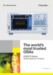
AQ6375
"LONG-WAVE" Optical Spectrum Analyzer
QUALITY
INNOVATION
APPLICATIONS
· Lasers
· Passive optical devices
· Optical fiber
For Gas sensing
Medical
Free-space communications
Optical fiber communications
FORESIGHT
Bulletin AQ6375-01E
www.yokogawa.com/tm/
WORLD CLASS PERFORMANCE
· Long wavelength measurement capability
· High wavelength accuracy & resolution
· High sensitivity
· High speed measurement
· USB for mouse, keyboard, and memory
· Remote operation (GP-IB, RS-232, Ethernet)
Subscribe to "Newswave" our free e-mail newsletter
Telecom and Beyond
The AQ6375 is the first bench-top optical spectrum analyzer covering the long wavelength over 2 µm.
It is designed for researchers and engineers who have been struggling with inadequate test
equipment to measure in these long wavelength ranges.
The AQ6375 achieves high speed measurements with high accuracy, resolution and sensitivity in a
compact frame, even while providing full analysis features and a built-in calibrator; troublesome
calibration steps and the development of external analysis software is no longer required. Those
features are indispensable to research, development, and manufacturing of optical devices in the
wavelength range from telecom band to 2 µm.
No other test system can achieve this high performance and ease of use at the same time.
Long Wavelength
1200 nm to 2400 nm
The AQ6375 covers not only
telecommunication wavelengths,
but also the long wavelength
region which is used for
environmental sensing, medical,
and industrial material
applications.
02
High Sensitivity
+20 dBm to -70 dBm
The AQ6375 can measure optical
power as low as -70 dBm, which
enables measurements of low
power sources or low power
output of a device under test.
Measurement sensitivity can be
chosen from seven categories
according to test applications and
measurement speed
requirements.
The spectrum of a white light source (yellow) and the background noise of AQ6375 (red)
High Resolution & Wide Dynamic Range
The AQ6375 uses a double-pass monochromator structure to
achieve high wavelength resolution (0.05 nm) and wide close-in
dynamic range (55 dB). Thus, closely allocated signals and noise
can be separately measured.
Dynamic range
55 dB or more
Measured HeNe Laser (1523 nm),
Close-in Dynamic range: @ peak±0.8 nm
Measurement Examples
1800nm DFB-LD
High speed Measurement
High Speed Sweep
With proprietary sweep technique the AQ6375 achieves a much faster sweep
speed than conventional measurement systems which use a monochromator.
Max. sweep time is only 0.5 sec. in 100 nm span.
Fast Command Processing and Data Transfer
Applying a fast microprocessor, the AQ6375 achieves very fast command
processing speed and Ethernet provides up to 100 times faster data transfer
speed than the GP-IB.
Free-Space Optical Input
Resolution: 50 pm, Span: 10 nm Sensitivity: HiGH1/CHOP
2010nm DFB-LD
Applicable fiber: SMF and MMF
The AQ6375 uses a free space input structure, not
having an optical fiber inside the monochromator, that
can handle multimode fibers. The free space input is also
beneficial for measurement repeatability.
Structure of
the optical input
Built-in Calibrator
The AQ6375 comes with the built-in calibrator for wavelength calibration and
optical alignment adjustment of the monochromator in order to maintain accurate
measurements. The calibration and adjustment are automatically performed and
completed within a couple of minutes.
Wavelength Calibration
Calibrates with the designate absorption line of Acetylene gas.
Resolution: 50 pm, Span: 20 nm Sensitivity: HiGH1/CHOP
Optical Alignment Adjustment
Corrects mechanical movements inside the monochromator caused by shock and
vibration.
Note. the wavelength can also be calibrated with an external light source.
03
EASY
ANALYSIS
Traces and Analysis Functions
nm / THz / cm-1
Analysis results
7 Traces
Multiple choices of x-axis indication
VARIOUS ANALYSIS FUNCTIONS
Thirteen types of built-in analysis functions are
available for popular applications. The analysis can be
automatically performd and provide results. The
functions include: Spectral width, Notch, SMSR, DFBLD, OSNR, EDFA, Filter, and more.
Marker & Search
7 TRACES & CALCULATION FUNCTIONS
The AQ6375 has seven individual traces for
measurement data. Some traces can be used for
calculations (subtraction between traces), max/min
hold, averaging, etc.
EASY
OPERATION
MARKER & SEARCH FUNCTIONS
cm-1 indication
Key & Mouse Operation
INTUITIVE OPERABILITY
The AQ6375 inherits our intuitive front panel design from our conventional models for proven easy use and
operation.
MOUSE & KEYBOARD OPERATION
You can easily operate the AQ6375 with only a mouse instead of the front
panel keys. The keyboard is useful for entering labels and file names.
The front panel key menu appears when right-clicking the mouse.
04
TRACE ZOOM CAPABILITY
Direct Parameter Entry
Trace zoom makes it possible to change display conditions, such as center wavelength and span, by clicking
and dragging the mouse to select the designated area to enlarge.
click
Original waveform
in measured wavelength range
Enlarged
waveform
OVERVIEW WINDOW
Once the trace is zoomed in, the overview
window appears and shows the entire trace. By
dragging the zoomed area border in this window
with the mouse, the display area in the main
trace window can be modified.
drag
Overview window
Operation in Overview window
EASY
DATA
HANDLING
USB & Internal Data Storage
The AQ6375 has two
USB 1.1 compatible
interfaces that support
large size removable
memory devices such
as Flash ROM and hard
disk drives (HDD).
Optical Spectrum Analyzer
AQ6375
USB STORAGE
THUMBNAIL FILE PREVIEW
The Thumbnail file preview function makes it easy
to find a particular file out of thousands of files in
internal and external storage.
LARGE INTERNAL STORAGE (5000+ traces)
The internal storage can save test setups,
waveforms, analysis results, and macro program
files. It is large enough to save more than five
thousand traces.
Thumbnail File Preview
Building Automated Test Systems
The AQ6375 is equipped with GP-IB, RS-232, and Ethernet (10/100Base-T) interfaces to be connected with
an external PC for remote access and building an automated test system. Macro Program is a useful built-in
function for making a simple auto test program.
COMPATIBLE WITH SCPI
The standard remote commands of the AQ6375 are
compatible with SCPI, which is an ASCII text based
standard code and format that conforms to IEEE488.2.
AQ6317 EMULATION MODE
MACRO PROGRAMMING
Macro programming enables user to easily create
test procedures by recording the user’s actual key
strokes and parameter selections. An external PC is
not required because the macro program can also
control external equipment through the remote
interfaces.
The AQ6375 supports private remote programming
codes of Yokogawa's best selling AQ6317 series for
users to easily upgrade from their current
automated test environment.
Measurement
Conditions
(Note. some commands may not be compatible due to changes
in specifications and functions.)
REMOTE
OPERATION
LabVIEW® DRIVER available
Control of external
equipment
Execution of a
measurement
ETHERNET
Control of external
equipment
Calculation
between traces
Example of Macro Program
AQ6375 Viewer
APPLICATION
SOFTWARE
- Emulation and Remote Control Software (Optional)
AQ6375Viewer is PC application software designed to work with Yokogawa’s AQ6375 Optical Spectrum
Analyzer.
Menu bar
05
EMULATION
The software has exactly the same user interface
and functions as the AQ6375 so that you can easily
display and analyze waveform data.
REMOTE CONTROL
Allows to control AQ6375 from anywhere on the
Ethernet network. Because of fast data transfer
speed of Ethernet, measurement data can be
updated in real time.
Note. the data update speed varies depending on network
performance and conditions.
Status bar
Panel key menu
Optical and Electrical Connections
FRONT PANEL
OPTICAL CONNECTORS
The AQ6375 adopts user
replaceable optical
connector for optical input
and calibration output,
enabling direct coupling to
major optical connector
types.
USB 1.1 INTERFACE
CONNECTIVITY
REAR PANEL
SERIAL
(RS-232)
TRIGGER IN (TLS Sync Sweep)
TRIGGER OUT
(TLS Sync Sweep)
ANALOG OUT
Mouse
KEYBOARD (PS/2)
VIDEO OUT(SVGA)
Keyboard
Memory
HDD
GP-IB (IEEE488.1/488.2)
GP-IB 1 : Allows remote control from your PC
GP-IB 2 : AQ6375 controls external instruments
ETHERNET (10/100BASE-T)
Optical Spectrum Analyzer
AQ6375
Specifications
Measurement
wavelength range 1)
Span 1)
Wavelength accuracy 1), 2), 3)
Wavelength repeatability 1), 2)
Measurement data point
Wavelength resolution
setting 1), 2)
Level sensitivity setting 10)
Level sensitivity 2), 4), 5), 7)
(Sensitivity: HIGH3)
Level accuracy 2), 4), 5), 6)
Level linearity 2), 4)
Maximum input power 2), 4)
Safe max. input power 2), 4)
Close-in dynamic range 1,) 2), 9)
Polarization dependency 2), 4), 6)
Sweep time 1), 7), 8)
Data
storage
06
Interface
Internal memory
Internal storage
External
File type
Remote
control
Category
Optical
connector
Printer
Display 12)
Power requirement
Environmental conditions
Dimensions and mass 11)
SM (9.5/125 µm),
GI (50/125 µm, 62.5/125 µm)
1200 to 2400 nm
Function
0.5 nm to full range and zero span
±0.05 nm (1520 to 1580 nm)
±0.1 nm (1580 to 1620 nm)
±0.5 nm (Full range)
±0.015 nm (1 min.)
101 to 50001
0.05, 0.1, 0.2, 0.5, 1.0 and 2.0 nm
NORM_HOLD, NORM_AUTO, NORMAL,
MID, HIGH1, HIGH2 and HIGH3
-62 dBm (1300 to 1500 nm)
-67 dBm (1500 to 1800 nm, 2200 to 2400 nm)
-70 dBm (1800 to 2200 nm)
±1.0 dB (1550 nm, input level: -20 dBm,
sensitivity: MID, HIGH1, HIGH2, or HIGH3)
±0.05 dB (Input level: -30 to +10 dBm,
sensitivity: HIGH1, HIGH2 or HIGH3)
+20 dBm (Per channel, full span)
+25 dBm (Total safe power)
45 dB (Peak ±0.4 nm, 1523 nm, resolution 0.05 nm)
55 dB (Peak ±0.8 nm, 1523 nm, resolution 0.05 nm)
±0.1 dB (1550 nm)
NORM AUTO: 0.5 sec, NORMAL: 1 sec,
MID: 10 sec, HIGH1: 20 sec
64 Traces, 64 programs, 3 template lines
Max. 128 MByte
USB storage (memory/HDD),
FAT32 format
CSV(text)/Binary, BMP/TIFF
GP-IB, RS-232 and Ethernet (TCP/IP)
AQ6317 series compliant commands
(IEEE488.1) and IEEE488.2 full support
GP-IB ⫻2 (standard/controller), RS-232,
Ethernet, USB1.1 ⫻2, PS/2 (keyboard),
SVGA output, Analog output port, Trigger
input port, Trigger output port
Optical input port (free-space): AQ9447 (*)
connector adapter required
Calibration output port (physical contact):
AQ9441 (*) connector adapter required
Built-in high-speed thermal printer (Factory option)
10.4-inch color LCD (Resolution: 800 ⫻ 600)
100 to 240 VAC, 50/60 Hz, approx. 150 VA
Operating temperature: +5 to +35°C
Storage temperature: -10 to +50°C
Humidity: 80 %RH or less (no condensation)
Approx. 426 (W) ⫻ 221 (H) ⫻ 459 (D) mm,
Approx. 27 kg (without printer option)
Standard
Accessories
Name
Power cable
User's manual (1set)
Macro program function (64 programs, 200
steps)
• Averaging number setting (1 to 999 times)
• Automatic measuring condition setting
• Sweep between line markers
• Zero span sweep (0 nm span)
• Automatic measurement data point setting
• Pulse light measurement
• External trigger measurement
• Sweep trigger
• Sweep status output
• Analog output
• TLS synchronized sweep
• Air/vacuum wavelength measurement
• Pass/Fail judgment with template
• Level scale (0.1 to 10 dB/div. and linear)
Display
• Vertical sub scale (0.1 to 10 dB/div. and linear)
• Reference level and position
• Vertical division number (8, 10 or 12)
• Horizontal scale: wavelength (nm)/ wave
number (cm-1)/ frequency (THz)
• Horizontal scale zoom in/out
• Measurement condition display
• Noise mask
• Data table
• Label
• Split display
• Power spectral density (dB/nm) display,
dB/km display, % display
• Template display
• 7 independent traces
Traces
• Write/Fix, Display/Blank setting
• Max./Min. hold
• Calculation between traces
• Roll (Sweep) averaging (2 to 100 times)
• Normalize
• Curve fit/Peak curve fit/Marker curve fit
• Trace copy/ clear function
Marker/Search • Marker: Delta marker (Max. 1024),
Vertical/Horizontal line marker
• Search: Peak, Next peak, Bottom, Next
bottom, Auto, Search between horizontal
line markers, Search in the zooming area
• Spectral width (threshold, envelope, RMS,
Analysis
Peak RMS, notch)
• WDM (OSNR) analysis
• EDFA-NF analysis
• Filter peak/bottom analysis
• WDM filter peak/bottom analysis
• DFB-LD/ FP-LD/ LED analysis
• SMSR analysis
• Power analysis
• PMD analysis
• Pass/Fail judgment with template
• Auto analysis
• Analysis between horizontal line markers
• Analysis in the zooming area
• Optical alignment function with built-in
Other
light source
• Wavelength calibration function
Dimensions
Unit : mm
(approx. inch)
REAR VIEW
13
(0.51)
426
(16.77)
14.8
(0.58)
13
(0.51)
221
(8.70)
Note:
1) Horizontal scale: wavelength display mode
2) At 23±5°C, with 9.5/125 µm single mode fiber, after 2 hours of warm-up, after optical
alignment with built-in reference light source
3) After wavelength calibration with built-in reference light source, sampling interval: 0.003 nm or
less, sensitivity: MID, HIGH1, HIGH2, or HIGH3
4) Vertical scale: absolute power display mode, resolution setting: 0.1 nm or greater
5) With 9.5/125 µm single mode fiber (B1.1 type defined on IEC60793-2, PC polished, mode
field diameter: 9.5 µm, NA: 0.104 to 0.107)
6) Temperature condition changes to 23±3°C for resolution 0.1 nm
7) Pulse light measurement mode: OFF, TLS sync sweep: OFF
8) Span: 100 nm or less, sampling point: 1001, number of average: 1
9) Sensitivity: HIGH 1, HIGH2, or HIGH3
10) Automatically goes to CHOP mode when HIGH1, HIGH2, or HIGH3 is selected
11) Excluding protector and handle
12) Liquid crystal display may include few defective pixels (within 0.002 % with respect to the total
number of pixels including RGB). There may be few pixels on the liquid crystal display that do
not emit all the time or remains ON all the time. Note that these are not malfunctions.
Automatic
measurement
Setting of
measuring
conditions
Q'ty
1
1
20
(0.79)
Applicable fiber
(1.26)
32
427
(18.22)
(1.26)
32
Factory Installed Options
BUILT-IN PRINTER
OPTICAL CONNECTOR ADAPTERS
An optional built-in thermal printer is
provided to instantly print out a
screenshot of the AQ6375's display,
analysis results, a marker list and a
macro program list.
For optical input port
Accessory: printer roll paper (1 roll)
For calibration output port
AQ9447 Connector Adapter
/FC, /SC, /ST
AQ9441 Universal Adapter
/RFC, /RSC, /RST
Ordering Information
Model and Suffix Codes
Model
735305
Power cable
Factory
Installed
Options
Suffix
Codes
-D
-F
-R
-Q
-H
-M
/FC
/SC
/ST
/RFC
/RSC
/RST
/B5
Accessories (Optional)
Descriptions
Optical Spectrum Analyzer AQ6375
Power cord (UL3P)
Power cord (CEE-C7)
Power cord (SAA-3P)
Power cord (BS3P Rectangular)
Power cord (BS3P Round)
Power cord (UL3P with 3P/2P converter)
AQ9447(FC) Connector adapter for optical input
AQ9447(SC) Connector adapter for optical input
AQ9447(ST) Connector adapter for optical input
AQ9441(FC) Universal adapter for calibration output
AQ9441(SC) Universal adapter for calibration output
AQ9441(ST) Universal adapter for calibration output
Built-in thermal printer
Name
Model
Suffix
codes
AQ9447 Connector adapter 810804602
-FCC
Connector type
-SCC
-STC
AQ9441 Universal adapter 813917321
-FCC
Connector type
-SCC
-STC
B9988AE
Printer roll paper
Specifications
For optical Input port
FC type
SC type
ST type
For calibration output port
FC type
SC type
ST type
10 m roll, 10 rolls/1 unit
07
Related Products
Optical Spectrum Analyzer
AQ6319
600 - 1700 nm
Resolution 10pm
Multi Application Test System
AQ2200 system
Modular Platform
Optical Spectrum Analyzer
AQ6370
600 - 1700 nm
Resolution 20pm
Tunable Laser Source
AQ2200-136
S+C+L band
Optical Spectrum Analyzer
AQ6331
PORTABLE 1200 - 1700 nm
Resolution 50pm
White Light Source
AQ4305
Broadband
AQ6375 Optical Spectrum Analyzer
Microsoft, MS, and Windows are registered trademarks or trademarks of Microsoft Corporation in
the US and other countries. LabVIEW is a U.S. registered trademark of National Instruments.
Other company names and product names appearing in this document are the registered
trademarks of their respective comparnies.
"Typical" or "typ." in this document means "Typical value", which is for reference, not guaranteed
specification.
Note
● Before operating the product, read the user's manual thoroughly
for proper and safe operation.
● If this product is for use with a system requiring safeguards that
directly involve personnel safety, please contact the Yokogawa
sales offices.
YOKOGAWA ELECTRIC CORPORATION
Communication & Measurement Business Headquarters /Phone: (81)-422-52-6768, Fax: (81)-422-52-6624
E-mail: [email protected]
YOKOGAWA CORPORATION OF AMERICA Phone: (1)-770-253-7000, Fax: (1)-770-251-6427
YOKOGAWA EUROPE B.V.
Phone: (31)-33-4641858, Fax: (31)-33-4641859
YOKOGAWA ENGINEERING ASIA PTE. LTD. Phone: (65)-62419933, Fax: (65)-62412606
Subject to change without notice.
[Ed : 01/b] Copyright ©2007
Printed in Japan, 711(KP)
MS-16E


