1
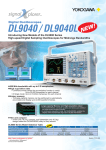
701930
701932
701931
701933
701928
NEW
701929
NEW
왎 Bandwidth: DC to 2/10/50/100 MHz; Current Measurement:
Max 30/150/500 A
왎 Clamp Configuration Makes Current Measurements Easy
The probe simply clamp around the conductor being measure.
왎 No External Amplifier Required: Connects Directly to DL
Series Instruments
The probes can be directly connected to the 1 MΩ BNC inputs on the DL series instruments
without the need for connection to a costly external amplifier. All probes in our lineup are
space-saving, easy to carry, and offer superior performance at a reasonable cost.
BNC input
Measured signal
701930/701931/701932/701933
Power supply
Probe power
701928/701929 support DL9000 probe I/F
왎 Powered by the DL’s Probe Power Supply Terminal
701930, 701931, 701932, 701933:
The probes are also compatible with external probe power supplies.
701928, 701929:
Support DL9000 probe I/F only.
왎 Current Values Can Be Read Directly on DL Series
Instruments
Using the current probe selection menu eliminates the need to enter current/voltage conversion values.
왎 Includes Demagnetizing Switch and Zero Adjust Functions
왎 701928/701929 support DL9000 probe I/F
Easily connect the 701928/29 with the DL9000 series oscilloscopes.
The probe power is supplied through the special connector.
Current probes are automatically recognized, and the DL9000’s display automatically changes to units of current (A).
Make current probe zero adjustments from the DL9000’s menu system.
(Zero adjustments require DL9000 firmware Ver3.64 or greater.)
Bulletin 7019-30E
www.yokogawa.com/tm/
Subscribe to "Newswave" our free e-mail newsletter
Yokogawa’s, 701928, 701929, 701930, 701931, 701932, and 701933 current probes make it easy
to observe current waveforms on an oscilloscope. Depending on your signal’s bandwidth and
maximum current, you can choose the right current probe for your measurement.
701932
701930
DC to 100 MHz/30 A
NEW
Output voltage rate*
Amplitude accuracy*
0.1 V/A
0 to 30 Arms: ±1% of rdg ±1 mV
To 50 Apeak: ±2% of rdg
(DC, and 45 to 66 Hz)
Noise*
Equivalent to 2.5 mArms or less (for 20 MHz band measuring
instrument)
Input impedance
Typical characteristic shown in figure 3
Temperature coefficient for sensitivity* ±2% or less
(within a range of 0 to 40°C when inputting 50 Hz, 30 Arms)
Maximum rated power
5.6 VA (Within maximum continuous input range)
Rated supply voltage
±12 V ±0.5 V (701933 only)
Operating temperature and humidity range 0 to 40°C, 80% RH or less (no condensation)
Storage temperature and humidity range -10 to 50°C, 80% RH or less (no condensation)
Effect of external magnetic field
Equivalent to a maximum of 20 mA (in a DC or 60 Hz, 400 A/m
magnetic field)
Maximum permitted circuit voltage
300 V CAT (insulated conductor)
Maximum diameter of measured conductor Ø5 mm
Cable length
Sensor cable: approx. 1.5 m (BNC terminal),
Power supply cable: approx. 1 m
External dimensions
Sensor (701929, 701933 common)
: approx. 175 (W) 18 (H) 40 (D) mm
Terminator (701933) : approx. 27 (W) 55 (H) 18 (D) mm
Terminator (701929) : approx. 29 (W) 80 (H) 24 (D) mm
Weight
701933: Approx. 230 g
701929: Approx. 190 g
Accessories
Instruction manual, soft case (701933), carring case (701929)
* In conjuction with a waveform measuring instrument with an input impedance of 1 MΩ ±1%
Standards Compliance
Safety
EN 61010-2-032:2002
Overvoltage category 1(anticipated transient overvoltage 1500 V),
Pollution degree 2
EN 61326:1997+A1:1998+A2:2001
EMC
Output voltage rate*
Amplitude accuracy*
0.1 V/A
0 to 30 Arms: ±1% of rdg ±1 mV
To 50 Apeak: ±2% of rdg
(DC, and 45 to 66 Hz)
Noise*
Equivalent to 2.5 mArms or less (for 20 MHz band measuring
instrument)
Input impedance
Typical Characteristic shown in figure 6
Temperature coefficient for sensitivity* ±2% or less
(within a range of 0 to 40°C when inputting 50 Hz, 30 Arms)
Maximum rated power
5.3 VA (Within maximum continuous input range)
Rated supply voltage
±12 V±0.5 V (701932 only)
Operating temperature and humidity range 0 to 40°C, 80% RH or less (no condensation)
Storage temperature and humidity range -10 to 50°C, 80% RH or less (no condensation)
Effect of external magnetic field
Equivalent to a maximum of 5 mA (in a DC or 60 Hz, 400 A/m
magnetic field)
Maximum permitted circuit voltage
300 V CAT1(insulated conductor)
Maximum diameter of measured conductor Ø5 mm
Cable length
Sensor cable: approx. 1.5 m (BNC terminal),
Power supply cable: approx. 1 m
External dimensions
Sensor (701928, 701932 common)
: approx. 175 (W) 18 (H) 40 (D) mm
Terminator (701932) : approx. 27 (W) 55 (H) 18 (D) mm
Terminator (701928) : approx. 29 (W) 80 (H) 24 (D) mm
Weight
701932: Approx. 240 g
701928: Approx. 190 g
Accessories
Instruction manual, carrying case (701932 and 701928)
* In conjuction with a waveform measuring instrument with an input impedance of 1 MΩ ±1%
EMC
0.01 V/A
0 to 150 Arms: ±1% of rdg ±1 mV
To 300 Apeak: ±2% of rdg
(DC, and 45 to 66 Hz)
Noise*
Equivalent to 25 mArms or less (for 20 MHz band measuring
instrument)
Input impedance
Typical characteristic shown in figure 9
Temperature coefficient for sensitivity* ±2% or less
(within a range of 0 to 40°C when inputting 50 Hz, 150 Arms)
Maximum rated power
5.5 VA(Within maximum continuous input range)
Rated supply voltage
±12 V±1 V
Operating temperature and humidity range 0 to 40°C, 80% RH or less (no condensation)
Storage temperature and humidity range -10 to 50°C, 80% RH or less (no condensation)
Effect of external magnetic field
Equivalent to a maximum of 150 mA (in a DC or 60 Hz, 400 A/m
magnetic field)
Maximum permitted circuit voltage
600 V CAT2(insulated conductor), 300 V CAT3(insulated
conductor)
Maximum diameter of measured conductor Ø20 mm
Cable length
Sensor cable: approx. 2 m (BNC terminal),
Power supply cable: approx. 1 m
External dimensions
Sensor: approx. 176 (W) 69 (H) 27 (D) mm
Terminator: approx. 27 (W) 55 (H) 18 (D) mm
Weight
Approx. 500 g
Accessories
Instruction manual, carrying case
* In conjuction with a waveform measuring instrument with an input impedance of 1 MΩ ±1%
-30
-40
-50
-30
-40
-50
100
10k
1M
1
100
10k
1M
20
15
10
5
1k
10k
100k
1M
10M
25
20
15
10
5
100M
10
100
1k
10k
1
100m
10m
1m
100k
Frequency [Hz]
Fig 3. Input impedance (typical)
1M
10M
100k
1M
10M
100M
1M
10M
-50
-60
-70
-80
100
100M
10k
100k
1M
10M
100k
1M
100M
Fig.10 Frequency characteristics (typical)
1000
100
50
100
10
10
100
1k
10k
100k
1M
10
10M
Frequency [Hz]
100
1k
10k
10M
Frequency [Hz]
Fig.11 Current derating VS. frequency
Fig.8 Current derating VS. frequency
100m
1
100m
10m
1m
100
1k
Frequency [Hz]
150
0
100M
Input impedance [Ω]
1
Input impedance [Ω]
10
10k
100k
Fig.5 Current derating VS. frequency
10
1k
10k
Frequency [Hz]
Fig.2 Current derating VS. frequency
-40
200
30
Frequency [Hz]
100
-70
Fig.7 Frequency characteristics (typical)
Maximum input current [A]
Maximum input current [A]
25
EMC
Frequency [Hz]
35
30
100
-60
1k
Fig.4 Frequency characteristics (typical)
35
10
-50
100M
EN 61010-2-032:2002
Overvoltage category 2, 3 (anticipated transient overvoltage
4000 V), Pollution degree 2
EN 61326-1:1997+A1:1998+A2:2001
-30
-40
Frequency [Hz]
Fig.1 Frequency characteristics (typical)
0.01 V/A
0 to 500 Arms: ±1% of rdg ±5 mV
To 700 Apeak: ±2% of rdg
(DC, and 45 to 66 Hz)
Noise*
Equivalent to 25 mArms or less (for 20 MHz band measuring
instrument)
Input impedance
Typical characteristic shown in figure 12
Temperature coefficient for sensitivity* ±2% or less
(within a range of 0 to 40°C when inputting 50 Hz, 500 Arms)
Maximum rated power
7.2 VA (Within maximum continuous input range)
Rated supply voltage
±12 V±0.5 V
Operating temperature and humidity range 0 to 40°C, 80% RH or less (no condensation)
Storage temperature and humidity range -10 to 50°C, 80% RH or less (no condensation)
Effect of external magnetic field
Equivalent to a maximum of 800 mA (in a DC or 60 Hz, 400 A/m
magnetic field)
Maximum permitted circuit voltage
600 V CAT2(insulated conductor), 300 V CAT3 (insulated
conductor)
Maximum diameter of measured conductor Ø20 mm
Cable length
Sensor cable: approx. 2 m (BNC terminal),
Power supply cable: approx. 1 m
External dimensions
Sensor: approx. 176 (W) 69 (H) 27 (D) mm
Terminator: approx. 27 (W) 55 (H) 18 (D) mm
Weight
Approx. 520 g
Accessories
Instruction manual, carrying case
* In conjuction with a waveform measuring instrument with an input impedance of 1 MΩ ±1%
-80
100M
Frequency [Hz]
Ambient temperature: 23±3°C, after power-on following 30 minutes
warmup period
DC to 2 MHz (-3dB) (typical characteristics shown in figure 10)
175 ns or less
500 Arms (derating according to frequency shown in figure 11)
700 Apeak (discontinuous)
Output voltage rate*
Amplitude accuracy*
-30
-20
-60
1
Bandwidth*
Rise time*
Maximum continuous input range
Maximum peak current value
Standards Compliance
Safety
EN 61010-2-032:2002
Overvoltage category 2, 3(anticipated transient overvoltage
4000 V), Pollution degree 2
EN 61326-1:1997+A1:1998+A2:2001
EMC
Amplitude [dB, 0dB=1 V]
Amplitude [dB, 0dB=1 V]
Amplitude [dB, 0dB=1 V]
EN 61010-2-032:2002
Overvoltage category 1(anticipated transient overvoltage 1500 V),
Pollution degree 2
EN61326:1997+A1:1998+A2:2001
701931 Specifications
Ambient temperature: 23±3°C, after power-on following 30 minutes
warmup period
DC to 10 MHz (-3dB) (typical characteristics shown in figure 7)
35 ns or less
150 Arms (derating according to frequency shown in figure 8)
300 Apeak (discontinuous)
500 Apeak at pulse width of 30 µs or less
Output voltage rate*
Amplitude accuracy*
Standards Compliance
Safety
Standards Compliance
Safety
-60
Input impedance [Ω]
Bandwidth*
Rise time*
Maximum continuous input range
Maximum peak current value
-10
-20
Maximum input current [A]
701930 Specifications
Ambient temperature: 23±3°C, after power-on following 30 minutes
warmup period
DC to 100 MHz (-3dB) (typical characteristics shown in figure 4)
3.5 ns or less
30 Arms (derating according to frequency shown in figure 5)
50 Apeak (discontinuous)
Bandwidth*
Rise time*
Maximum continuous input range
Maximum peak current value
-10
2
DC to 100 MHz/30 A
DL9000 probe I/F
701932/701928 Specifications
Ambient temperature: 23±3°C, after power-on following 30 minutes
warmup period
DC to 50 MHz (-3dB) (typical characteristics shown in figure 1)
7 ns or less
30 Arms (derating according to frequency shown in figure 2)
50 Apeak (discontinuous)
Bandwidth*
Rise time*
Maximum continuous input range
Maximum peak current value
701928
DC to 50 MHz/30 A
DL9000 probe I/F
701933/701929 Specifications
DC to 2 MHz/500 A
NEW
Maximum input current [A]
701929
701931
DC to 10 MHz/150 A
Amplitude [dB, 0dB=1 V]
DC to 50 MHz/30 A
Input impedance [Ω]
701933
0.1
0.01
0.001
1k
10k
100k
1M
10M
100M
1m
10k
100k
1M
Frequency [Hz]
Frequency [Hz]
Fig 6. Input impedance (typical)
10m
Fig 9. Input impedance (typical)
10M
10k
100k
1M
Frequency [Hz]
Fig 12. Input impedance (typical)
3
Relationship between the Current being
Measured and Probe’s Current Consumption
(Typical Values)
When using the DL to power the current probes, make sure
that the total current consumption of the probes does not
exceed the DL’s probe power rating. For the probe power
rating of each DL model, please visit
www.yokogawa.com/tm/probe/
600
500
400
300
200
100
0
-100
-200
-300
-400
-500
-600
-50
Power cable
-D
-F
-H
-Q
-R
Description
30 Arms DC to 50 MHz, support probe power
30 Arms DC to 100 MHz, support probe power
150 Arms DC to 10 MHz, support probe power
500 Arms DC to 2 MHz, support probe power
30 Arms DC to 50 MHz, support DL9000 probe I/F *1
30 Arms DC to 100 MHz, support DL9000 probe I/F *1
Connects up to four active probes. Power voltage: 100 to 240 V,
Output current: ±2.5 A
UL, CSA Standard
VDE Standard
GB Standard
BS Standard
AS Standard
701934 Probe Power Supply
-40
-30
-20
-10
0
10
20
30
40
50
DC input, positive
pole of power
supply
DC input, negative
pole of power
supply
AC (50 Hz) input,
positive pole of
power supply
AC (50 Hz) input,
negative pole of
power supply
50
DC input, positive
pole of power
supply
DC input, negative
pole of power
supply
AC (50 Hz) input,
positive pole of
power supply
AC (50 Hz) input,
negative pole of
power supply
-40
-30
-20
-10
0
10
20
30
40
Features
A power supply for current probes, FET probes, and
differential probes. Probes work with both DL probe
power connectors and the 701934 probe power supply.
Supplies power for up to four probes, including large
current probes. Supports both AC100 V and 200 V
power supply requirements.
Specifications
Number of power supply connectors 4
Output voltage
±12 V±0.5 V
Rated output current
+12 V: 2.5 A, –12 V: 2.5 A (the total value
of four outputs)
Operating temperature and humidity range 0 to 40°C, 80% RH or
less (no condensation)
Storage temperature and humidity range -10 to 50°C, 80% RH or
less (no condensation)
Rated supply voltage
AC100 to 240 V (50/60 Hz)
Maximum rated power
170 VA
External dimensions
Approx. 80 (W) ⫻ 119 (H) ⫻ 200 (D) mm
Weight
Approx. 1.1 kg
Notice
701934 does not support 71928 and 701929.
Exterior Dimensions
(mm)
701933, 701932
1500
175
55
18
Current probe (701932, 701928)
Current consumption (mA)
Probe power supply
Model Suffix Code
701933
701932
701930
701931
701929
701928
701934
*1) 701928/701929 can be used only with DL9000 series. DL9000 series with the firmware Ver3.64 or greater is necessary.
Measure current (A)
600
500
400
300
200
100
0
-100
-200
-300
-400
-500
-600
-50
Name
Current probe
27
Current consumption (mA)
Current probe (701933, 701929)
Current probe and power supply model numbers and
suffix codes
Measure current (A)
1000
40
sensor cable: 1.5 m
Maximum diameter of measured conductor: Ø5 mm
-200
-100
0
300
DC input, positive
pole of power
supply
DC input, negative
pole of power
supply
AC (50 Hz) input,
positive pole of
power supply
AC (50 Hz) input,
negative pole of
power supply
100 200 300 400 500 600 700
DC input, positive
pole of power
supply
DC input, negative
pole of power
supply
AC (50 Hz) input,
positive pole of
power supply
AC (50 Hz) input,
negative pole of
power supply
100
200
power supply cable: 1 m
18
700
600
500
400
300
200
100
0
-100
-200
-300
-400
-500
-600
-700
-300
(22.5)
Current consumption (mA)
Current probe (701930)
701930, 701931
1000
34
Measure current (A)
27
27
2000
176
64
sensor cable: 2 m
Maximum diameter of measured conductor: Ø20 mm
19
18
power supply cable: 1 m
701928, 701929
18
29
0
Measure current (A)
55
69
29
600
500
400
300
200
100
0
-100
-200
-300
-400
-500
-600
-700 -600 -500 -400 -300 -200 -100
66
Current consumption (mA)
Current probe (701931)
80
175
1. To avoid short circuits and electric shocks when using a current probe, use only
with power lines carrying voltages within the rating limit of the current probe.
2. To avoid short circuits and electric shocks when the clamp core tip is opened,
do not use on bare conductors.
3. Before operating the product, read the user’s manual thoroughly for proper and
safe operation.
YOKOGAWA ELECTRIC CORPORATION
Communication & Measurement Business Headquarters /Phone: (81)-422-52-6768, Fax: (81)-422-52-6624
E-mail: [email protected]
YOKOGAWA CORPORATION OF AMERICA Phone: (1)-770-253-7000, Fax: (1)-770-251-6427
YOKOGAWA EUROPE B.V.
Phone: (31)-33-4641858, Fax: (31)-33-4641859
YOKOGAWA ENGINEERING ASIA PTE. LTD. Phone: (65)-62419933, Fax: (65)-62412606
sensor cable:1500 ± 100
24
NOTICE
40
5
Subject to change without notice.
[Ed : 03/b] Copyright ©2007
Printed in Japan, 710(KP)
MS-16E