1
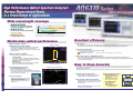
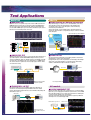
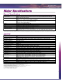
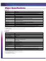
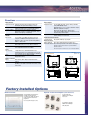
Optical Spectrum Analyzer
AQ6370B / AQ6373 / AQ6375
VIS to NIR Applications
High resolution & dynamic range
Fast measurement
GP-IB/ Ethernet remote control
USB
QUALITY
INNOVATION
FORESIGHT
Bulletin AQ6370SR-01EN
Wide wavelength coverage
- AQ6370B
350
Standard model optimized to the wavelengths
often used in telecommunication applications.
1200
2400
AQ6373
- AQ6373
The VIS is from 380 to 780nm.
AQ6370B
600
for short-wavelength including visible light (VIS).
300
500
AQ6375
700
900
1700
1100 1300 1500 1700 1900 2100 2300 2500
wavelength (nm)
- AQ6375
The AQ6373 and AQ6375 can cover the entire wavelength range from 350nm through 2400nm.
for long-wavelength over 2um.
World-class optical performance
Excellent efficiency
Fast Sweep
High Resolution 0.02nm*
& High Dynamic Range 70dB*
Dynamic Range
The advanced monochromator achieves high wavelength resolution and high
close-in dynamic range. With the sharper spectral characteristics of the
monochromator, spectral signals in close proximity can be separated clearly and
measured accurately.
High Sensitivity: -90dBm*
With an advanced monochromator, faster electrical circuits, and noise reduction techniques, the AQ6370 series achieves fast measurement speed even
when measuring a steep spectrum from DFB-LD or DWDM signals, or when measuring a low power signal from a broadband light source.
Fast Remote Interface
AQ6370 series provides faster remote control and data transfer capability.
100x Ethernet interface is 100 times faster
(compared with the conventional GP-IB used on Yokogawa AQ6317 series optical spectrum analyzer)
10x GP-IB interface is 10 times faster
70dB
Weak optical signals can be measured accurately and quickly.
Wide Span Sweep yet High Resolution
- 7 sensitivity settings
Can be selected according to test applications and measurement speed
requirements. The settings correspond to the sensitivity from -60 dBm to -90
dBm in approx 5dB steps, in the case of AQ6370B.
The 50,001 data sampling points expands measurement range in a single sweep while keeping a high wavelength resolution.This makes your
measurement easier and more efficient than conventional systems that use a low number of sampling points and require multiple partial measurements
to cover the complete wavelength range.
Peak±0.4nm
- High dynamic mode
Obtains a better dynamic range by reducing the influence of stray-light,
which is caused when the input is a strong optical signal.
Pulsed Light Measurement
AQ6370B, Peak ±0.4nm, resolution setting 0.02 nm,
High dynamic mode:ON, typical
Measurement Power Range
Peak-Hold and External trigger mode
Measure a pulse peak spectrum of a pulsed light signal.
Often used in the transmission loop testing of telecommunication systems, and
also in the low power measurement at the early stage of laser chip development to
catch the peak power of a pulsed signal.
Ambient condition change, vibration and shock to an optical precision product, like an optical spectrum analyzer, will effect the optical components, and
eventually degrade optical performance.
Using standard functions, AQ6370 series can maintain its high optical performance within a couple of minutes so that you can quickly start a measurement.
+20 dBm
Optical alignment function
Automatically aligns the optical path in the monochromator
using the built-in source to maintain high performance.
Free Space Input
- Multimode and single mode fiber on the same OSA.
- Small insertion loss variation at the input connector
increases measurement repeatability.
- No damage connecting fibers because there is no
physical contact.
Wavelength calibration function
-90 dBm
Optical input structure
(note. AQ6373 uses a fixed connector)
* Those numbers are for AQ6370B, and the dynamic range is a typical value.
2
Easy to Keep Accurate
Automatically calibrates the spectrum analyzer with the built-in
wavelength reference or an external light source, to ensure the
wavelength accuracy.
AQ6370B, Sensitivity setting: HIGH3, High dynamic mode: OFF, typical
Note. There are cases that the optical alignment and wavelength calibration
function cannot correct optical performance.
Periodical calibration is also required separately.
Built-in calibration source
- Wavelength reference source
For the wavelength calibration and
optical alignment
Available on AQ6370B and AQ6375
Note. SM 9.5/125µm fiber is required.
EE-LED
Acetylene absorption
cell
- Optical alignment source
For the optical alignment
Available on AQ6373
Note. GI 50/125µm fiber is required.
An external light source is required
for the wavelength calibration.
Calibration
output
Structure of the built-in wavelength
reference source.
3
Easy Operation
Various Analysis Functions
Trace zooming
Mouse & Keyboard operation
7 individual traces
Spectrum analysis functions
- Change display conditions, such as center wavelength and span,
by clicking and dragging the mouse.
- Enlarge your area of interest instantly and move it at will.
- No need for another measurement to modify the display conditions.
- Front panel operation proven intuitive and easy to use
by our many of users.
- Even easier with a mouse.
- The keyboard helps enter labels and file names.
- Simultaneous multi-trace display
- Calculation between traces
13+ data analysis functions for popular applications
Original waveform
in measured wavelength range
click
Point the item to modify
(subtraction between traces)
WDM (OSNR) Analysis Function
•Built-in analysis functions:
- Max/Min hold
- Spectral width analysis
- WDM (OSNR) analysis
- WDM-NF (EDFA) analysis
- DFB-LD analysis
- FP-LD analysis
- LED analysis
- SMSR analysis
- Optical power analysis
Modify settings
using the keys
on the screen
Enlarged
waveform
- Various filter analysis
- Color analysis (AQ6373 only)
Result table
drag
Building Automated
Test System
Overview window
Macro
Programming
USB ports
Mouse
Keyboard
Build a simple
auto-measurement system
Memory
- No external PC is required.
- Easy to create test program by
recording the user's actual key
strokes and parameter
selections.
- Can control external equipment
through the remote interfaces.
HDD
Measurement
Conditions
Control of external
equipment
Execution of a
measurement
Control of external
equipment
Calculation
between traces
USB 1.1 compatible
Fast remote interfaces
- GP-IB, RS-232, and Ethernet (10/100Base-T) interfaces
Easy Data Handling
Easy to control with an external PC and to build an automated test system.
- Improve the testing throughput of test systems
by the fast measurement, command processing, and data transfer speed.
USB Storage
-USB 1.1 compatible interfaces support large size removable
memory devices such as Flash ROM and hard disk drives (HDD).
- Easy way to carry a large number of data files.
128MB Internal storage
Thumbnail File Preview
Easy to find a particular file out of thousands of files in internal
and external storage.
Optical input
Calibration output
(Free space input)
(Wavelength reference source or
optical alignment source)
ETHERNET
Optical connectors
for optical input & calibration output
AQ6370B & AQ6375: Universal type (FC, SC or ST).
AQ6373: FC type
- Save over 5,000 data files
SCPI compatible
The standard remote commands are compatible with SCPI, which is an ASCII
text based standard code and format that conforms to IEEE-488.2.
File types and formats:
AQ6317 Emulation Mode
- Trace: Binary and ASCII (CSV)
- Graphic: Bitmap (BMP) and TIFF
- Analysis results: Binary and ASCII (CSV)
- Template: ASCII (CSV)
- System setup: Binary
- Macro program: Binary
Supports the private remote commands of Yokogawa's best selling AQ6317
series and AQ6315 for users to easily upgrade from their current automated test
environment.
Note. some commands may not be compatible due to changes in specifications and functions.
Universal type connectors
4
LabVIEW® Driver available
5
AQ6370B 600 to 1700nm
Wavelength accuracy : ±0.02 nm
Wavelength resolution : 0.02 to 2 nm
Max input power : +20 dBm
Level sensitivity : −90 dBm
Dynamic range : 70dB (typ)
Single-mode and Multimode fibers
Built-in wavelength reference source
for wavelength calibration and optical alignment
● Universal type optical connectors
● Optimized performance and functions for WDM systems
STANDARD
OSNR measurement on DWDM system
●
●
●
●
●
●
●
- High wavelength linearity and Level flatness (1450 to 1620nm)
- WDM (OSNR) analysis and EDFA analysis
The WDM(OSNR)analysis function finds channel
wavelength. power, channel spacing, and OSNR.
Optical amplifier(EDFA)measurement
● X-axis : nm / THz
➤Applications
- Optical active devices (Laser diode/Fiber laser/Optical amplifier/Optical transceiver)
- Optical passive devices (Filter/FBG/AWG/WSS/ROADM/Optical fiber)
- Optical transmission equipment (DWDM, CWDM)
- Development support of Applied photonics equipment
AQ6375 1200 to 2400nm
Wavelength accuracy : ±0.05 nm
Wavelength resolution : 0.05 to 2 nm
Max input power : +20 dBm
Level sensitivity : −70 dBm
Dynamic range : ≥55dB
Single-mode and Multimode fibers
Built-in wavelength reference source
for wavelength calibration and optical alignment
● Universal type optical connectors
● Various analysis functions
● X-axis : nm / THz / cm-1
●
●
●
●
●
●
●
The WDM-NF(EDFA)analysis finds channel
wavelength, Gain and Noise figure(NF).
LONG
wavelength
The spectrum of a white light source (yellow)
and the background noise of AQ6375 (red)
2010nm DFB-LD measurement
➤Applications
- Optical active devices (Laser diode/Fiber laser)
- Optical passive devices (Filter/FBG/Specialty optical fiber)
- Development support of Applied photonics equipment
•Measurement/sensing area: Gas/Environmental sensing
•Medical/Bio area
•Telecom area: Optical fiber/Free-space communication
Resolution: 0.05nm, Span: 20 nm, Sensitivity: HiGH1/CHOP
6
AQ6373 350 to 1200nm
SHORT
852nm DFB-LD measurement
● Wavelength accuracy: ±0.05 nm
(Resolution setting: 0.02nm)
● Wavelength resolution : 0.02 to 10 nm
and 0.01nm (400 to 470nm)
● Max safe input power : +20 dBm
● Level sensitivity : −80 dBm
● Dynamic range : ≥60dB
● Single-mode, Multimode, and Large-core fibers
● Built-in optical alignment source
● Wavelength calibration
wavelength
FWHM = 0.024nm
with an external reference source
● Various analysis functions including the
Color analysis function for VIS
The details of oscillation modes can be
measured with high resolution of 0.02nm
405nm FP-LD measurement
(Resolution setting: 0.01nm)
FWHM = 0.011nm
➤Applications
- Optical active devices (Laser diode/Fiber laser)
- Optical passive devices (Filter/FBG/Specialty optical fiber)
- Development support of Applied photonics equipment
•Medical/Bio area: Laser therapy, DNA sequencing, Microscope
•Industrial area: Laser micro-machine, laser maker
•Home Electronics area: Laser projector, Next-gen optical disc, LED products
•Measurement/sensing area: LIDAR, Interferometer
•Telecom area: Plastic Optical fiber (POF) communication
In 400-470nm range, achieves even higher resolution.
AQ6370 Viewer
Real-time remote operation
(Optional application software)
The AQ6370Viewer is a package of PC application software for the AQ6370
series Optical Spectrum Analyzer.
• The same user interface and functions as the mainframe
• Display and analyze waveform data acquired by the mainframe
• Remote control and file transfer capability
Viewer function
Trace data files saved on the AQ6370 series can be retrieved and analyzed
on a PC.
Note. Measurement cannot be initiated in the Viewer mode
Remote control function
The remote control allows you to set measurement conditions and to
execute a measurement on the mainframe from anywhere on an Ethernet
network. Upon completion of a measurement on the mainframe, the
AQ6370Viewer downloads and shows the updated traces.
Note. Data transfer speed varies depending on PC and network performance. The program function is
not supported. Some other restrictions may apply.
File transfer function
Transfer files from the mainframe to the PC and vice versa. The macro
program file edited on the AQ6370Viewer can also be transferred to the
mainframe.
Remote control &
File transfer
Menu bar
TCP/IP
NETWORK
AQ6370B Viewer
AQ6370B connected to LAN
- PC Requirements
<Hardware> HDD: 50 MB or more of available disk space, Memory: 512 MB or more
<OS> Windows 2000 (Service Pack 4 or later) or Windows XP (Service Pack 1 or later)
- Bundled software AQ6370Viewer consists of the following software.
Status bar
Panel key menu
- AQ6370 Viewer
- AQ6370B Viewer
- AQ6375 Viewer
- AQ6373 Viewer
: for AQ6370 Optical spectrum Analyzer (discontinued)
: for AQ6370B Optical spectrum Analyzer
: for AQ6375 Optical spectrum Analyzer
: for AQ6373 Optical spectrum Analyzer
7
Test Applications
AQ6375
AQ6370B
■ WDM OSNR TEST
■ Global warming gas (Methane) measurement
AQ6370B’s wide close-in dynamic range allows accurate OSNR measurement of
DWDM transmission systems (up to 50 GHz spacing). The built-in WDM analysis
function analyzes the measured waveform and shows peak wavelength, peak
level and OSNR of WDM signals up to 1024 channels simultaneously. The curve fit
function is used to accurately measure noise levels.
The global warming gasses such as CO2, SO2, NOX, and Methane, have strong
optical absorption around 2µm wavelength region. The distribution and
concentration of those gasses in the atmosphere can be determined by
measuring the optical absorbance.
Simply connecting the collected sunlight using an optical fiber, AQ6375 can
measure the optical absorbance corresponding to the gas' column concentration
in the atmosphere.
Optical absorption spectrum of Methane
Use the sun
as a light source
Column amount
Example of analyzed data table
6.6dB
λ1
Tx2
λ2
Tx3
λ3
Tx4
λ4
TxN
λn
Optical
amplifier
AQ6375
MUX
Tx1
AQ6370B
Example of WDM OSNR analysis
AQ6373
■ SIMPLE EDFA TEST
The ASE interpolation method is used to measure gain, NF, and key parameters for
optical fiber amplifier evaluation. With WDM-NF analysis function, up to 1024
channels of multiplexed signals can simultaneously be tested. An ASE level for NF
measurements is calculated by using a curve-fit function for each WDM channel.
The curve-fit and source spontaneous emission (SSE) suppress function enhance
a measurement accuracy.
■ Visible LED Test
The optical spectrum of visible LEDs used in lighting, indication, measurement
and applications can be measured and analyzed.
By supporting the large core fiber input, AQ6373 can efficiently get the LED light
and measure its spectrum.The built-in color analysis function automatically
evaluates a dominant wavelength and chromatic coordinates.
Optical fiber
AQ2212
Multiplexer
AQ6373
Optical amplifier
AQ6370B
Visible LED
WDM waveform before/after
amplification by EDFA
■ TRANSCEIVER / LD TEST
In conjunction with bit error rate test (BERT) equipment, the AQ6370B can
measure the center wavelength and spectral width of transceivers and LD
modules. Various built-in analysis functions, such as DFB-LD, FP-LD (VCSEL), and
LED facilitate test process.
BERT(PPG)
Transceiver
AQ6370B
Color analysis of White LED
All models
■ PASSIVE COMPONENT TEST
In conjunction with a white light source, an ASE light source or other broadband
light source, you can simply perform evaluation of passive devices such as WDM
filters and FBG. The AQ6370 series' superb optical characteristics enable higherresolution and wider dynamic range measurements.
The built-in optical filter analysis function simultaneously reports peak/bottom
wavelength, level, crosstalk, and ripple width.
AQ2211
AQ4305 White Light Source
Example waveform and
analysis result of transceiver
output
8
AQ6370 series
DUT (FBG, WDM filter, etc. )
Example of CWDM filter measurement
Major Specifications
General Specifications
Items
Electrical interface
Remote control *
Data storage
Display **
Printer
Dimensions
Mass
Power requirement
Environmental conditions
Specifications
GP-IB x 2 (standard/controller), RS-232, Ethernet, USB 1.1 x2, PS/2 (keyboard), SVGA output, Analog output port,
Trigger input port, Trigger output port
GP-IB, RS-232, Ethernet (TCP/IP)
AQ6317 series compatible commands (IEEE488.1) and IEEE488.2
Internal storage: Max. 128M Bytes, Internal memory: 64 Traces, 64 programs, 3 template lines,
External storage: USB storage (memory/HDD), FAT32 format
File types: CSV (text), Binary, BMP, TIFF
10.4-inch color LCD (Resolution: 800 x 600)
Built-in thermal printer (Factory installed option)
426 (W) x 221 (H) x 459 (D) mm (Excluding protector and handle)
AQ6370B: 19kg, AQ6373: 20kg, AQ6375: 27kg (Without printer option)
100 to 240 VAC, 50/60 Hz, approx. 150 VA
Performance guarantee temperature: + 18 to + 28 C˚,
Operating temperature: +5 to +35 C˚, Storage temperature: -10 to +50 C˚, Humidity: ≤80 %RH (no condensation)
* : Some AQ6317 series commands may not be compatible due to changes in specifications or functions.
** : Liquid crystal display may include few defective pixels (within 0.002% with respect to the total number of pixels including RGB). There may be few pixels on the liquid crystal display that do not emit all the time or remains ON all the time. These are not malfunctions.
AQ6370B
Items
Wavelength range *1
Span *1
Wavelength accuracy *1, *2, *5
Wavelength linearity *1, *2, *5
Wavelength repeatability *1, *2,
Wavelength resolution setting *1, *2
Wavelength resolution accuracy *1, *2, *5
Minimum sampling resolution *1
Number of sampling
Level sensitivity setting
High dynamic mode
Level sensitivity *2, *3, *4, *7
Maximum input power *2, *3
Maximum safe input power *2, *3
Level accuracy *2, *3, *4, *6
Level linearity *2, *3
Level flatness *2, *3, *6
Polarization dependence *2, *3, *6
Dynamic range *1, *2, *8
Applicable fiber
Optical connector
Built-in calibration light source
Sweep time *1, *7, *9
Warm-up time
*1 :
*2 :
*3 :
*4 :
*5 :
*6 :
*7 :
*8 :
*9 :
Specifications
600 to 1700 nm
0.5 nm to 1100 nm (full span), and 0nm
± 0.02 nm (1520 to 1580 nm), ± 0.04 nm (1450 to 1520 nm, 1580 to 1620 nm), ± 0.10 nm (Full range)
± 0.01 nm (1520 to 1580 nm), ± 0.02 nm (1450 to 1520 nm, 1580 to 1620 nm)
± 0.005 nm (1 min.)
0.02, 0.05, 0.1, 0.2, 0.5, 1 and 2 nm
± 5 % (1450 to 1620 nm, Resolution setting: ≥ 0.1 nm, Resolution correction: ON, Number of sampling: AUTO)
0.001 nm
101 to 50001, AUTO
NORM_HOLD, NORM_AUTO, NORMAL, MID, HIGH1, HIGH2 and HIGH3
SWITCH (Sensitivity: MID, HIGH1-3)
-90 dBm (1300 to 1620 nm), -80 dBm (1000 to 1300 nm), -60 dBm (600 to 1000 nm) (Sensitivity: HIGH3)
+ 20 dBm (Per channel, full range)
+ 25 dBm (Total input power)
± 0.4 dB (1310/1550 nm, Input level: -20 dBm, Sensitivity: MID, HIGH1-3)
± 0.05 dB (Input level: -50 to +10 dBm, Sensitivity: HIGH1-3)
± 0.1 dB (1520 to 1580 nm), ± 0.2 dB (1450 to 1520 nm, 1580 to 1620 nm)
± 0.05 dB (1550/1600 nm), ± 0.08 dB (1310 nm)
37 dB (Peak ± 0.1 nm, Resolution: 0.02 nm), 55 dB (Peak ± 0.2 nm, Resolution: 0.02 nm),
45 dB (Peak ± 0.2 nm, Resolution: 0.05 nm), 62 dB (Peak ± 0.4 nm, Resolution: 0.05 nm),
40 dB (Peak ± 0.2 nm, Resolution: 0.1 nm), 57 dB (Peak ± 0.4 nm, Resolution: 0.1 nm)
SM, GI (50/125 µm, 62.5/125 µm)
Optical input : AQ9447 (*) connector adapter (option) required.
Calibration output: AQ9441 (*) connector adapter (option) required. (*):connector type FC, SC, or ST type
Wavelength reference source (For optical alignment and wavelength calibration)
NORM_AUTO: 0.5 sec, NORMAL: 1 sec, MID: 2 sec, HIGH1: 5 sec, HIGH2: 20 sec, HIGH3: 75sec
Minimum 1 hour (After warming up, optical alignment adjustment with built-in light source is required.)
Horizontal scale: Wavelength display mode.
With 9.5/125 µm single mode fiber, after 2 hours of warm-up, after optical alignment with built-in reference light source.
Vertical scale: Absolute power display mode, Resolution setting: ≥ 0.05 nm, Resolution correction: OFF.
With 9.5/125 µm single mode fiber (B1.1 type defined on IEC60793-2, PC polished, mode field diameter: 9.5 µm, NA : 0.104 to 0.107).
After wavelength calibration with built-in reference light source.
Temperature condition changes to 23 ± 3C˚ at 0.05 nm resolution setting.
High dynamic mode: OFF, Pulse light measurement mode: OFF, TLS sync sweep: OFF, Resolution correction: OFF.
1523nm, High dynamic mode: SWITCH, Resolution correction: OFF
Span: ≤ 100 nm, Number of sampling: 1001, Average number: 1.
9
Major Specifications
AQ6373
Items
Wavelength range *1
Span *1
Wavelength accuracy *1
Wavelength resolution setting *1, *2
Minimum sampling resolution *1
Number of sampling
Level sensitivity setting
High dynamic mode
Level sensitivity *3
Maximum safe input power *3
Level accuracy *2
Level linearity *3
Dynamic range *1
Applicable fiber
Optical connector
Built-in calibration light source
Sweep time *1, *4
Warm-up time
Specifications
350 to 1200 nm
0.5 nm to 850 nm (full span), and 0nm
± 0.05 nm (633nm), ± 0.20 nm (400 to 1100nm) (After wavelength calibration with 633nm He-Ne laser.)
0.02, 0.05, 0.1, 0.2, 0.5, 1, 2, 5, 10 nm (full range), and 0.01nm (400 to 470 nm)
0.001 nm
101 to 50001, AUTO
NORM_HOLD, NORM_AUTO, NORMAL, MID, HIGH1, HIGH2 and HIGH3
SWITCH (Sensitivity: MID, HIGH1-3)
-80 dBm (500 to 1000 nm), -60 dBm (400 to 500 nm, 1000 to 1100 nm)
(Typical, Resolution setting: ≥ 0.2nm, Averaging: 10 times, Sensitivity: HIGH3)
+ 20 dBm (550 to 1100nm), + 10 dBm (400 to 550nm) (Total input power)
± 1.0 dB (850 nm, Input level: -20 dBm, Resolution setting: ≥ 0.2 nm, Sensitivity: MID, HIGH1-3,
SMF [MFD5µm@850nm, NA0.14])
± 0.2 dB (Input level: -40 to 0 dBm, Sensitivity: HIGH1-3)
60 dB (Peak ± 0.5 nm, Resolution setting: 0.02 nm, 633nm, Sensitivity: HIGH1-3)
SM, GI (50/125 µm, 62.5/125 µm), Large core fiber (up to 800 µm)
FC type (Optical input and Calibration output)
Optical alignment source (for optical alignment. Wavelength reference is not equipped.)
NORM_ AUTO: 0.5 sec, NORMAL : 1 sec, MID: 2 sec, HIGH1: 5 sec, HIGH2: 20 sec, HIGH3: 75 sec
Minimum 1 hour (After warming up, optical alignment adjustment with built-in light source is required.)
Performance and functions can be limited by type of used fiber. The specifications are only guaranteed when a single mode fiber in which light travels in single mode at measured wavelength is used. In case that measured wavelength is less than the cut-off wavelength
of the used fiber, or a multimode fiber is used, a measured spectrum may be inaccurate due to a speckle noise. Please be cautious especially when measuring high coherency sources like gas laser and Laser diode.
*1 :
*2 :
*3 :
*4 :
Horizontal scale: Wavelength display mode.
Actual wavelength resolution varies according to a measured wavelength. Actual resolution at 10nm resolution setting is about 8nm at most.
Vertical scale: Absolute power display mode.
High dynamic mode: OFF, Number of sampling: 1001, Average number: 1, Span: ≤ 100 nm excluding 450 to 470 nm and 690 to 700 nm.
AQ6375
Items
Wavelength range *1
Span *1
Wavelength accuracy *1, *2, *5
Wavelength repeatability *1, *2
Wavelength resolution setting *1, *2
Minimum sampling resolution *1
Number of sampling
Level sensitivity setting
Level sensitivity *2, *3, *4, *6
Maximum input power *2, *3
Maximum safe input power *2, *3
Level accuracy *2, *3, *4, *8
Level linearity *2, *3
Polarization dependence *2, *3, *8
Dynamic range *1, *2
Applicable fiber
Optical connector
Built-in calibration light source
Sweep time *1, *6, *7
Warm-up time
*1 :
*2 :
*3 :
*4 :
*5 :
*6 :
*7 :
*8 :
10
Specifications
1200 to 2400 nm
0.5 nm to 1200 nm (full span), and 0nm
± 0.05 nm (1520 to 1580 nm), ± 0.10 nm (1580 to 1620 nm), ± 0.50 nm (Full range)
± 0.015 nm (1 min.)
0.05, 0.1, 0.2, 0.5, 1 and 2 nm
0.002 nm
101 to 50001, AUTO
NORM_HOLD, NORM_AUTO, NORMAL, MID, HIGH1, HIGH2 and HIGH3
(Only High dynamic mode (/CHOP) in HIGH1-3)
-70 dBm (1800 to 2200 nm), -67 dBm (1500 to 1800 nm, 2200 to 2400 nm), -62 dBm (1300 to 1500 nm)
(Sensitivity: HIGH3)
+ 20 dBm (Per channel, full wavelength range)
+ 25 dBm (Total input power)
± 1.0 dB (1550 nm, input level: -20 dBm, Sensitivity: MID, HIGH1-3)
± 0.05 dB (Input level: -30 to +10 dBm, Sensitivity: HIGH1-3)
± 0.1 dB (1550 nm)
45 dB (Peak ± 0.4 nm, resolution: 0.05 nm), 55 dB (Peak ± 0.8 nm, resolution: 0.05 nm) (1523nm, Sensitivity: HIGH1-3)
SM, GI (50/125 µm, 62.5/125 µm)
Optical input : AQ9447 (*) connector adapter (option) required.
Calibration output: AQ9441 (*) connector adapter (option) required. (*):connector type FC, SC, or ST type
Wavelength reference source (for optical alignment and wavelength calibration)
NORM_AUTO: 0.5 sec, NORMAL: 1 sec, MID: 10 sec, HIGH1: 20 sec
Minimum 1 hour (After warming up, optical alignment adjustment with built-in light source is required.)
Horizontal scale: Wavelength display mode.
With 9.5/125 µm single mode fiber, after 2 hours of warm-up, after optical alignment with built-in reference light source.
Vertical scale: Absolute power display mode, Resolution setting: ≥ 0.1 nm.
With 9.5/125 µm single mode fiber (B1.1 type defined on IEC60793-2, PC polished, mode field diameter: 9.5 µm, NA: 0.104 to 0.107).
After wavelength calibration with built-in reference light source, Sampling resolution: ≤ 0.003 nm, Sensitivity: MID, HIGH1-3
Pulse light measurement mode: OFF, TLS sync sweep: OFF.
Span: ≤ 100 nm, Number of sampling: 1001, Average number: 1.
Temperature condition changes to 23 ± 3C˚ at 0.1 nm resolution setting.
Functions
Measurement
Data analysis
Measurement mode CW light, Pulsed light, External trigger, Air/vacuum
wavelength, TLS synchronized sweep (excl. AQ6373)
Sweep mode
Repeat, Single, AUTO (Self-configuration), Sweep
between line markers, Zero span sweep (0 nm span)
Condition settings Center wavelength, Span, Number of sampling,
Wavelength resolution, Sensitivity, High dynamic mode,
Number of averaging (1 to 999 times)
Others
Sweep status output, Analog output
Analysis functions
Others
Display
Vertical scale
Level scale(0.1 to 10 dB/div. and linear), Level subscale(0.1 to 10 dB/div. and linear), Reference level,
Divisions (8, 10 or 12), power spectral density (dB/nm),
dB/km, %, Noise mask
Horizontal scale
Wavelength (nm), Frequency (THz),
Wave number (cm-1) (AQ6375 only), Trace zoom in/out
Display mode & items Normal display, Split display, Data table,
Label, Template, Measurement conditions
Automated measurement
Program function
Others
7 independent traces, Maximum/Minimum hold,
Calculation between traces, Normalizing, Curve fit, Peak
curve fit, Marker curve fit, Roll averaging (2 to 100 times)
Trace copy/clear function, Write/Fix setting,
Display/Blank setting
64 programs, 200 steps per program
Other functions
Optical alignment
Auto-optical alignment with built-in light source
Wavelength calibration Auto-wavelength calibration with built-in wavelength
reference source (AQ6370&AQ6375 only) or an external
reference source.
Note. AQ6373 requires an external reference source for wavelength calibration.
Trace
Trace functions
Spectral width (threshold, envelope, RMS, peak-RMS,
notch), WDM (OSNR) analysis,
EDFA-NF analysis (excl.AQ6373), Filter peak/bottom analysis,
WDM filter peak/bottom analysis,
DFB-LD/ FP-LD/ LED analysis, SMSR analysis,
Power analysis, PMD analysis, Color analysis (AQ6373 only),
Pass/Fail analysis with template
Auto-analysis(ON/OFF), Analysis between horizontal line
markers, Analysis in zoomed area
Dimensions
Unit : mm
(approx. inch)
REAR VIEW
Marker & Search
Marker
Search
Delta markers (Max. 1024), Vertical/horizontal line
markers
Peak, Bottom, Next peak, Next bottom, Auto-search
(On/OFF), Search between horizontal line markers, Search
zoomed area
14.8
(0.58)
426
(16.77)
427
(18.22)
(1.26)
32
13
(0.51)
20
( 0.79)
221
(8.70)
13
(0.51)
(1.26)
32
Factory Installed Options
Built-in Printer
Optical connector adapters (AQ6370B&AQ6375)
An optional built-in thermal printer is
provided to instantly print out a
screenshot of the display, the analysis
results, a marker list and a macro
program list.
Accessory: printer roll paper (1 roll)
For optical input port
AQ9447 Connector Adapter
/FC, /SC, /ST
For calibration output port
AQ9441 Universal Adapter
/RFC, /RSC, /RST
11
Ordering Information
Models and Suffix codes
Accessories (optional)
AQ6370B & AQ6375
Model
735302
735305
Power
cord
Suffix code
Descriptions
AQ6370B Optical Spectrum Analyzer
AQ6375 Optical Spectrum Analyzer
-D
UL/CSA Standard
-F
VDE Standard
-R
AS Standard
-Q
BS Standard
-H
GB Standard
Factory
/FC
AQ9447(FC) Connector adapter for optical input
installed
/SC
AQ9447(SC) Connector adapter
options
/ST
AQ9447(ST) Connector adapter
/RFC AQ9441(FC) Universal adapter for calibration output
/RSC AQ9441(SC) Universal adapter
/RST AQ9441(ST) Universal adapter
/B5 Built-in thermal printer
Model
735371
Suffix code
810804602
Connector type -FCC
-SCC
-STC
813917321
Connector type -FCC
-SCC
-STC
751535-E5
B9988AE
Descriptions
AQ6370 Viewer
(Including AQ6370, AQ6370B, AQ6375,
and AQ6373 Viewers)
AQ9447 Connector Adapter
FC type
SC type
ST type
AQ9441 Universal Adapter
FC type
SC type
ST type
19 inch Rack mount kit
Printer roll paper (10 m roll, 10 rolls/1 unit)
AQ6373
Model
735303
Power
cord
Suffix code
Descriptions
AQ6373 Optical Spectrum Analyzer
-D
UL/CSA Standard
-F
VDE Standard
-R
AS Standard
-Q
BS Standard
-H
GB Standard
Factory installed /B5 Built-in thermal printer
option
Related Products
Multi Application Test System
Tunable Laser Source
White Light Source
AQ2200 system
AQ2200-136
AQ4305
Modular Platform
Note
S+C+L band
● Before operating the product, read the user's manual thoroughly
for proper and safe operation.
● If this product is for use with a system requiring safeguards that
directly involve personnel safety, please contact the Yokogawa
sales offices.
Broadband
Microsoft, MS, and Windows are registered trademarks or trademarks of Microsoft Corporation in
the US and other countries. LabVIEW is a U.S. registered trademark of National Instruments.
Other company names and product names appearing in this document are the registered
trademarks of their respective comparnies.
"Typical" or "typ." in this document means "Typical value", which is for reference, not guaranteed
specification.
YOKOGAWA ELECTRIC CORPORATION
Measurement Business Headquarters /Phone: (81)-422-52-6768, Fax: (81)-422-52-6624
E-mail: [email protected]
YOKOGAWA CORPORATION OF AMERICA Phone: (1)-770-253-7000, Fax: (1)-770-251-6427
YOKOGAWA EUROPE B.V.
Phone: (31)-88-4641000, Fax: (31)-88-4641111
YOKOGAWA ENGINEERING ASIA PTE. LTD. Phone: (65)-62419933, Fax: (65)-62412606
Subject to change without notice.
[Ed : 01/b] Copyright ©2009
Printed in Japan, 912(KP)
MS-19E