1
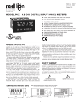
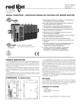
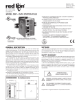
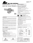
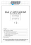
Bulletin No. DP5-F Drawing No. LP0546 Released 04/15 Tel +1 (717) 767-6511 Fax +1 (717) 764-0839 www.redlion.net MODEL DP5 – 1/8 DIN ANALOG INPUT PANEL METERS UL C PROCESS, VOLTAGE, CURRENT, AND TEMPERATURE INPUTS 5-DIGIT 0.56" HIGH LED DISPLAY PROGRAMMABLE FUNCTION KEYS/USER INPUT 9 DIGIT TOTALIZER (INTEGRATOR) WITH BATCHING OPTIONAL CUSTOM UNITS OVERLAY W/BACKLIGHT NEMA 4X/IP65 SEALED FRONT BEZEL US LISTED R IND. CONT. EQ. 51EB GENERAL DESCRIPTION SAFETY SUMMARY The DP5 Panel Meters offer many features and performance capabilities to suit a wide range of industrial applications. These meters are available in three different models to handle various analog inputs, including DC Voltage/Current, Process, and Temperature Inputs. Refer to pages 4 and 5 for the details on the specific models. The meters provide a MAX and MIN reading memory with programmable capture time. The capture time is used to prevent detection of false max or min readings which may occur during start-up or unusual process events. The signal totalizer (integrator) can be used to compute a time-input product. This can be used to provide a readout of totalized flow, calculate service intervals of motors or pumps, etc. The totalizer can also accumulate batch weighing operations. Once the meters have been initially configured, the parameter list may be locked out from further modification. The meters have been specifically designed for harsh industrial environments. With NEMA 4X/IP65 sealed bezel and extensive testing of noise effects to CE requirements, the meter provides a tough yet reliable application solution. DIMENSIONS In inches (mm) MA X MIN TOT 8.8.8.8.8 DSP PAR F1 3.80 (96.5) F2 V All safety related regulations, local codes and instructions that appear in this literature or on equipment must be observed to ensure personal safety and to prevent damage to either the instrument or equipment connected to it. If equipment is used in a manner not specified by the manufacturer, the protection provided by the equipment may be impaired. CAUTION: Risk of Danger. Read complete instructions prior to installation and operation of the unit. CAUTION: Risk of electric shock. Note: Recommended minimum clearance (behind the panel) for mounting clip installation is 2.1" (53.4) H x 5.0" (127) W. 1.95 (49.5) 1.75 (44.5) RST .10 (2.5) 4.10 (104.1) 1 12 13 14 15 1 2 3 4 5 6 7 16 17 18 19 8 9 10 11 3.60 (91.4) 20 21 22 23 24 25 1.75 (44.5) Table Of Contents Ordering Information. . . . . . . . . . . . . . . . . . . . 2 General Meter Specifications . . . . . . . . . . . . . 3 Universal DC Input Panel Meter. . . . . . . . . . . 4 Process Input Panel Meter. . . . . . . . . . . . . . . 4 Thermocouple and RTD Input Meter. . . . . . . . 5 Accessories. . . . . . . . . . . . . . . . . . . . . . . . . . . 5 Installing the Meter . . . . . . . . . . . . . . . . . . . . . 6 Setting the Jumpers . . . . . . . . . . . . . . . . . . . . 6 Wiring the Meter . . . . . . . . . . . . . . . . . . . . . . . 7 Reviewing the Front Buttons and Display. . . . 9 Programming the Meter. . . . . . . . . . . . . . . . . 10 Factory Service Operations. . . . . . . . . . . . . . 17 Parameter Value Chart. . . . . . . . . . . . . . . . . 19 Programming Overview. . . . . . . . . . . . . . . . . 20 Ordering Information Meter Part Numbers DP5 0 0 D - DC Volt/Current Input P - Process Input T - Thermocouple and RTD Input 0 - Red LED Display 0 - 85 to 250 VAC 1 - 11 to 36 VDC, 24 VAC Accessories Part Number TYPE Accessories MODEL NO. PAXLBK DESCRIPTION PART NUMBERS Units Label Kit Accessory (Not required for DP5T) 2 PAXLBK10 General Meter Specifications 1. DISPLAY: 5 digit, 0.56" (14.2 mm) red LED, (-19999 to 99999) 2. POWER: AC Versions: AC Power: 85 to 250 VAC, 50/60 Hz, 10 VA Isolation: 2300 Vrms for 1 min. to all inputs. DC Versions: DC Power: 11 to 36 VDC, 11 W AC Power: 24 VAC, ± 10%, 50/60 Hz, 10 VA Isolation: 500 Vrms for 1 min. to all inputs (50 V working). 3. ANNUNCIATORS: MAX - maximum readout selected MIN - minimum readout selected TOT - totalizer readout selected, flashes when total overflows Units Label - optional units label backlight 4. KEYPAD: 3 programmable function keys, 5 keys total 5. A/D CONVERTER: 16 bit resolution 6. UPDATE RATES: A/D conversion rate: 10 readings/sec. Step response: 200 msec. max. to within 99% of final readout value (digital filter and internal zero correction disabled) 700 msec. max. (digital filter disabled, internal zero correction enabled) Display update rate: 1 to 10 updates/sec. Max./Min. capture delay time: 0 to 3275 sec. 7. DISPLAY MESSAGES: “OLOL” - Appears when measurement exceeds + signal range. “ULUL” - Appears when measurement exceeds - signal range DP5T: “OPEN” - Appears when open sensor is detected. DP5T: “SHrt” - Appears when shorted sensor is detected (RTD only) “. . . .” - Appears when display values exceed + display range. “- . . .” - Appears when display values exceed - display range. 8. INPUT CAPABILITIES: See specific product specifications, pages 4-5 9. EXCITATION POWER: See specific product specifications, pages 4-5 10. LOW FREQUENCY NOISE REJECTION: Normal Mode: > 60 dB @ 50 or 60 Hz ±1%, digital filter off Common Mode: >100 dB, DC to 120 Hz 11. USER INPUT: One software defined user input Max. Continuous Input: 30 VDC Isolation To Sensor Input Common: Not isolated. Do not tie commons together. Response Time : 50 msec. max. Logic State: Jumper selectable for sink/source logic INPUT STATE SINKING INPUTS 22 KΩ pull-up to +5 V SOURCING INPUTS 22 KΩ pull-down Active VIN < 0.9 VDC VIN > 3.6 VDC Inactive VIN > 3.6 VDC VIN < 0.9 VDC 14. ENVIRONMENTAL CONDITIONS: Operating Temperature Range: 0 to 50°C Storage Temperature Range: -40 to 60°C Vibration to IEC 68-2-6: Operational 5-150 Hz, 2 g Shock to IEC 68-2-27: Operational 25 g. Operating and Storage Humidity: 0 to 85% max. RH non-condensing Altitude: Up to 2000 meters 15. CERTIFICATIONS AND COMPLIANCES: CE Approved EN 61326-1 Immunity to Industrial Locations Emission CISPR 11 Class A Safety requirements for electrical equipment for measurement, control, and laboratory use: EN 61010-1: General Requirements EN 61010-2-030: Particular Requirements for Testing and Measuring Circuits RoHS Compliant UL Recognized Component: File #E179259 UL Listed: File #E137808 UL Listed: File #E156876 DP5T Only Type 4X Enclosure rating (Face only) IP65 Enclosure rating (Face only) IP20 Enclosure rating (Rear of unit) Refer to EMC Installation Guidelines section of the bulletin for additional information. 16. CONNECTIONS: High compression cage-clamp terminal block Wire Strip Length: 0.3" (7.5 mm) Wire Gage: 30-14 AWG copper wire Torque: 4.4-5.3 inch-lbs (0.5-0.6 N-m) 17. CONSTRUCTION: This unit is rated for NEMA 4X/IP65 outdoor use. IP20 Touch safe. Installation Category II, Pollution Degree 2. One piece bezel/case. Flame resistant. Synthetic rubber keypad. Panel gasket and mounting clip included. 18. WEIGHT: 7 oz. (200 g) 12. TOTALIZER: Time Base: second, minute, hour, or day Time Accuracy: 0.01% typical Decimal Point: 0 to 0.0000 Scale Factor: 0.001 to 65.000 Low Signal Cut-out: -19,999 to 99,999 Total: 9 digits, display alternates between high order and low order readouts 13. MEMORY: Nonvolatile E2PROM retains all programmable parameters and display values. 3 Model DP5D - Universal DC Input FOUR VOLTAGE RANGES (300 VDC Max) FIVE CURRENT RANGES (2A DC Max) 24 VDC TRANSMITTER POWER DP5D SPECIFICATIONS INPUT RANGES: INPUT RANGE ACCURACY* (18 to 28°C) 0.03% of reading +0.03 µA 0.03% of reading ±2 mADC +0.3 µA 0.03% of reading ±20 mADC +3µA 0.05% of reading ±200 mADC +30 µA 0.5% of reading ±2 ADC +0.3 mA 0.03% of reading ±200 mVDC +30 µV 0.03% of reading ±2 VDC +0.3 mV 0.03% of reading ±20 VDC +3 mV 0.05% of reading ±300 VDC +30 mV ±200 µADC ACCURACY* (0 to 50°C) IMPEDANCE/ COMPLIANCE 0.12% of reading +0.04µA 0.12% of reading +0.4 µA 0.12% of reading +4 µA 0.15% of reading +40 µA 0.7% of reading +0.4 mA 0.12% of reading +40 µV 0.12% of reading +0.4 mV 0.12% of reading +4 mV 0.15% of reading +40 mV MAX CONTINUOUS RESOLUTION OVERLOAD 1.11 Kohm 15 mA 10 nA 111 ohm 50 mA 0.1 µA 11.1 ohm 150 mA 1 µA 1.1 ohm 500 mA 10 µA 0.1 ohm 3A 0.1 mA 1.066 Mohm 100 V 10 µV 1.066 Mohm 300 V 0.1 mV 1.066 Mohm 300 V 1 mV 1.066 Mohm 300 V 10 mV * After 20 minute warm-up. Accuracy is specified in two ways: Accuracy over an 18 to 28°C and 10 to 75% RH environment; and accuracy over a 0 to 50°C and 0 to 85%RH (non-condensing environment). Accuracy over the 0 to 50°C range includes the temperature coefficient effect of the meter. EXCITATION POWER: Transmitter Power: 24 VDC, ±5%, regulated, 50 mA max. Model DP5P - Process Input DP5P SPECIFICATIONS SENSOR INPUTS: INPUT (RANGE) ACCURACY* (18 to 28°C) ACCURACY* (0 to 50°C) MAX IMPEDANCE/ DISPLAY CONTINUOUS COMPLIANCE RESOLUTION OVERLOAD 20 mA 0.03% of 0.12% of (-2 to 26 mA) reading +2 µA reading +3 µA 20 ohm 150 mA 1 µA 10 VDC 0.03% of 0.12% of (-1 to 13 VDC) reading +2 mV reading +3 mV 500 Kohm 300 V 1 mV * After 20 minute warm-up. Accuracy is specified in two ways: Accuracy over an 18 to 28°C and 10 to 75% RH environment; and accuracy over a 0 to 50°C and 0 to 85%RH (non-condensing environment). Accuracy over the 0 to 50°C range includes the temperature coefficient effect of the meter. EXCITATION POWER: Transmitter Power: 24 VDC, ±5%, regulated, 50 mA max. 4 DUAL RANGE INPUT (20 mA or 10 VDC) 24 VDC TRANSMITTER POWER Model DP5T - Thermocouple DP5T SPECIFICATIONS READOUT: Resolution: Variable: 0.1, 0.2, 0.5, or 1, 2, or 5 degree Scale: F or C Offset Range: -19,999 to 99,999 display units THERMOCOUPLE INPUTS: Input Impedance: 20 MΩ Lead Resistance Effect: 0.03µV/ohm Max. Continuous Overvoltage: 30 V INPUT TYPE RANGE ACCURACY* ACCURACY* STANDARD (18 to 28°C) (0 to 50°C) T -200 to 400°C -270 to -200°C 1.2°C ** 2.1°C E -200 to 871°C -270 to -200°C 1.0°C ** 2.4°C J -200 to 760°C 1.1°C 2.3°C K -200 to 1372°C -270 to -200°C 1.3°C ** 3.4°C R -50 to 1768°C 1.9°C S -50 to 1768°C B WIRE COLOR ANSI BS 1843 ITS-90 (+) blue (-) red (+) white (-) blue ITS-90 (+) purple (+) brown (-) red (-) blue ITS-90 (+) white (-) red ITS-90 (+) yellow (+) brown (-) red (-) blue 4.0°C ITS-90 no standard (+) white (-) blue 1.9°C 4.0°C ITS-90 no standard (+) white (-) blue 100 to 300°C 300 to 1820°C 3.9°C 2.8°C 5.7°C 4.4°C ITS-90 no standard no standard N -200 to 1300°C -270 to -200°C 1.3°C ** 3.1°C ITS-90 (+) orange (+) orange (-) red (-) blue C (W5/W26) 0 to 2315°C 1.9°C 6.1°C ASTM no E988-90*** standard (+) yellow (-) blue no standard *After 20 min. warm-up. Accuracy is specified in two ways: Accuracy over an 18 to 28°C and 15 to 75% RH environment; and Accuracy over a 0 to 50°C and 0 to 85% RH (non condensing) environment. Accuracy specified over the 0 to 50°C operating range includes meter tempco and ice point tracking effects. The specification includes the A/D conversion errors, linearization conformity, and thermocouple ice point compensation. Total system accuracy is the sum of meter and probe errors. Accuracy may be improved by field calibrating the meter readout at the temperature of interest. ** The accuracy over the interval -270 to -200°C is a function of temperature, ranging from 1°C at -200°C and degrading to 7°C at -270°C. Accuracy may be improved by field calibrating the meter readout at the temperature of interest. *** These curves have been corrected to ITS-90. Accessories UNITS LABEL KIT (PAXLBK) - Not required for DP5T Each meter has a units indicator with backlighting that can be customized using the Units Label Kit. The backlight is controlled in the programming. Each DP5T meter is shipped with °F and °C overlay labels which can be installed into the meter’s bezel display assembly. 5 and RTD Input THERMOCOUPLE AND RTD INPUTS CONFORMS TO ITS-90 STANDARDS TIME-TEMPERATURE INTEGRATOR RTD INPUTS: Type: 3 or 4 wire, 2 wire can be compensated for lead wire resistance Excitation current: 100 ohm range: 165 µA 10 ohm range: 2.6 mA Lead resistance: 100 ohm range: 10 ohm/lead max. 10 ohm range: 3 ohms/lead max. Max. continuous overload: 30 V DIRECT READOUT: RANGE ACCURACY* ACCURACY* STANDARD INPUT TYPE (18 to 28°C) (0 to 50°C) *** Input range: -10 to 65 mV 100 ohm Pt 0 to 400 ohms, high range -200 to 850°C 0.4°C 1.6°C IEC 751 alpha = .00385 0 to 25 ohms, low range Display range: 100 ohm Pt -19999 to 99999 no official alpha = .003919 120 ohm Nickel alpha = .00672 10 ohm Copper alpha = .00427 -200 to 850°C 0.4°C 1.6°C -80 to 260°C 0.2°C 0.5°C -100 to 260°C 0.4°C 0.9°C standard no official standard no official standard INPUT TYPE RANGE ACCURACY* (18 to 28°C) ACCURACY* (0 to 50°C) Direct mV range Direct 100 ohm range Direct 10 ohm range -10 to 65mV (1 µV res.) 0 to 400 Ω (10 MΩ res.) 0 to 25 Ω (1 MΩ res.) 0.02% of reading + 4µV 0.02% of reading + 0.04 Ω 0.04% of reading + 0.005 Ω 0.12% of reading + 5µV 0.12% of reading + 0.05 Ω 0.20% of reading + 0.007 Ω 1.0 Installing The Meter Installation While holding the unit in place, push the panel latch over the rear of the unit so that the tabs of the panel latch engage in the slots on the case. The panel latch should be engaged in the farthest forward slot possible. To achieve a proper seal, tighten the latch screws evenly until the unit is snug in the panel (Torque to approximately 7 in-lbs [79N-cm]). Do not over-tighten the screws. The DP5 meets NEMA 4X/IP65 requirements when properly installed. The unit is intended to be mounted into an enclosed panel. Prepare the panel cutout to the dimensions shown. Remove the panel latch from the unit. Slide the panel gasket over the rear of the unit to the back of the bezel. The unit should be installed fully assembled. Insert the unit into the panel cutout. Installation Environment The unit should be installed in a location that does not exceed the maximum operating temperature and provides good air circulation. Placing the unit near devices that generate excessive heat should be avoided. The bezel should be cleaned only with a soft cloth and neutral soap product. Do NOT use solvents. Continuous exposure to direct sunlight may accelerate the aging process of the bezel. Do not use tools of any kind (screwdrivers, pens, pencils, etc.) to operate the keypad of the unit. PANEL BEZEL LATCHING SLOTS PANEL LATCH PANEL CUT-OUT 3.62 +.03 -.00 (92 +.8 -.0 ) LATCHING TABS PANEL GASKET 1.77+.02 -.00 (45 +.5 -.0 ) PANEL MOUNTING SCREWS 2.0 Setting the Jumpers User Input Logic Jumper The meter can have up to two jumpers that must be checked and / or changed prior to applying power. The two jumpers are: Input Range and User Input Logic. The following Jumper Selection Figures show an enlargement of the jumper area. To access the jumpers, remove the meter base from the case by firmly squeezing and pulling back on the side rear finger tabs. This should lower the latch below the case slot (which is located just in front of the finger tabs). It is recommended to release the latch on one side, then start the other side latch. This jumper selects the logic state of the user input. If the user input is not used, it is not necessary to check or move this jumper. DP5D Jumper Selection Input Range Jumper One jumper is used for voltage or current input ranges. Select the proper input range high enough to avoid input signal overload. Only one jumper is allowed in this area. Do not have a jumper in both the voltage and current ranges at the same time. Avoid placing the jumper across two ranges. JUMPER SELECTIONS The indicates factory setting. Main Circuit Board INPUT RANGE JUMPER CURRENT VOLT ±300V ±20V ±2V ±200mV ±2A ±200mA ±20mA ±2mA ±200µA JUMPER LOCATIONS USER INPUT LOGIC JUMPER VOLT/ OHM SOURCE SINK 6 CURRENT USER INPUT DP5P Jumper Selection Main Circuit Board JUMPER SELECTIONS The indicates factory setting. USER INPUT LOGIC JUMPER SINK USER INPUT JUMPER LOCATION SOURCE REAR TERMINALS DP5T Jumper Selection RTD Input Jumper One jumper is used for RTD input ranges. Select the proper range to match the RTD probe being used. It is not necessary to remove this jumper when not using RTD probes. Main Circuit Board JUMPER SELECTIONS The indicates factory setting. RTD INPUT JUMPER JUMPER LOCATION RTD INPUT JUMPER LOCATION 100 ohms 10 ohms USER INPUT LOGIC JUMPER SINK SOURCE USER INPUT REAR TERMINALS 3.0 Wiring the Meter WIRING OVERVIEW grounded. This is especially useful in applications where cable runs are long and portable two-way radios are used in close proximity or if the installation is near a commercial radio transmitter. Also, Signal or Control cables within an enclosure should be routed as far away as possible from contactors, control relays, transformers, and other noisy components. 4. Long cable runs are more susceptible to EMI pickup than short cable runs. 5. In extremely high EMI environments, the use of external EMI suppression devices such as Ferrite Suppression Cores for signal and control cables is effective. The following EMI suppression devices (or equivalent) are recommended: Fair-Rite part number 0443167251 (RLC part number FCOR0000) Line Filters for input power cables: Schaffner # FN2010-1/07 (Red Lion Controls # LFIL0000) 6. To protect relay contacts that control inductive loads and to minimize radiated and conducted noise (EMI), some type of contact protection network is normally installed across the load, the contacts or both. The most effective location is across the load. a. Using a snubber, which is a resistor-capacitor (RC) network or metal oxide varistor (MOV) across an AC inductive load is very effective at reducing EMI and increasing relay contact life. b. If a DC inductive load (such as a DC relay coil) is controlled by a transistor switch, care must be taken not to exceed the breakdown voltage of the transistor when the load is switched. One of the most effective ways is to place a diode across the inductive load. Most RLC products with solid state outputs have internal zener diode protection. However external diode protection at the load is always a good design practice to limit EMI. Although the use of a snubber or varistor could be used. RLC part numbers: Snubber: SNUB0000 Varistor: ILS11500 or ILS23000 7. Care should be taken when connecting input and output devices to the instrument. When a separate input and output common is provided, they should not be mixed. Therefore a sensor common should NOT be connected to an output common. This would cause EMI on the sensitive input common, which could affect the instrument’s operation. Visit RLC’s web site at http://www.redlion.net/emi for more information on EMI guidelines, Safety and CE issues as they relate to Red Lion Controls products. Electrical connections are made via screw-clamp terminals located on the back of the meter. All conductors should conform to the meter’s voltage and current ratings. All cabling should conform to appropriate standards of good installation, local codes and regulations. It is recommended that power supplied to the meter (DC or AC) be protected by a fuse or circuit breaker. When wiring the meter, compare the numbers embossed on the back of the meter case against those shown in wiring drawings for proper wire position. Strip the wire, leaving approximately 0.3" (7.5 mm) bare lead exposed (stranded wires should be tinned with solder). Insert the lead under the correct screwclamp terminal and tighten until the wire is secure. (Pull wire to verify tightness.) Each terminal can accept up to one #14 AWG (2.55 mm) wire, two #18 AWG (1.02 mm), or four #20 AWG (0.61 mm). EMC INSTALLATION GUIDELINES Although Red Lion Controls Products are designed with a high degree of immunity to Electromagnetic Interference (EMI), proper installation and wiring methods must be followed to ensure compatibility in each application. The type of the electrical noise, source or coupling method into a unit may be different for various installations. Cable length, routing, and shield termination are very important and can mean the difference between a successful or troublesome installation. Listed are some EMI guidelines for a successful installation in an industrial environment. 1. A unit should be mounted in a metal enclosure, which is properly connected to protective earth. 2. Use shielded cables for all Signal and Control inputs. The shield connection should be made as short as possible. The connection point for the shield depends somewhat upon the application. Listed below are the recommended methods of connecting the shield, in order of their effectiveness. a. Connect the shield to earth ground (protective earth) at one end where the unit is mounted. b. Connect the shield to earth ground at both ends of the cable, usually when the noise source frequency is over 1 MHz. 3. Never run Signal or Control cables in the same conduit or raceway with AC power lines, conductors, feeding motors, solenoids, SCR controls, and heaters, etc. The cables should be run through metal conduit that is properly 7 3.1 POWER WIRING AC Power Terminal 1: VAC Terminal 2: VAC AC 1 DC Power AC 2 Terminal 1: +VDC Terminal 2: -VDC + _ 1 2 - + 3.2 INPUT SIGNAL WIRING DP5D INPUT SIGNAL WIRING Before connecting signal wires, the Input Range Jumper should be verified for proper position. 5 +24V Load 300VDC MAX. - 2A DC MAX. 2 WIRE TRANSMITTER Terminal 3: +VDC (signal) Terminal 5: -VDC (common) Terminal 6: +Volt supply CURRENT COMM +24V EXC 6 VOLT 4 Voltage Signal (3 wire requiring excitation) 3 4 5 6 Vout Iout COMM. 3 WIRE TRANSMITTER +Vs + Potentiometer Signal (3 wire requiring excitation) CAUTION: Sensor input common is NOT isolated from user input common. In order to preserve the safety of the meter application, the sensor input common must be suitably isolated from hazardous live earth referenced voltages; or input common must be at protective earth ground potential. If not, hazardous live voltage may be present at the User Input and User Input Common terminals. Appropriate considerations must then be given to the potential of the user input common with respect to earth common. Terminal 3: Wiper Terminal 5: Low end of pot. Terminal 6: High end of pot. Input Range Jumper: 300 Volt Module 1 Input Range: 300 Volt Note: The Apply signal scaling style should be used because the signal will be in volts. +24V EXC - Terminal 4: +ADC (signal) Terminal 5: -ADC (common) Terminal 6: +Volt supply COMM - 4 Current Signal (3 wire requiring excitation) VOLT + + Terminal 4: -ADC Terminal 6: +ADC +24V EXC 5 Current Signal (2 wire requiring excitation) CURRENT COMM 3 Terminal 4: +ADC Terminal 5: -ADC COMM VOLT Terminal 3: +VDC Terminal 5: -VDC Current Signal (self powered) CURRENT Voltage Signal (self powered) 3 5 6 300V INPUT R=1K to 10K DP5P INPUT SIGNAL WIRING + - 10 VDC MAX. + - LOAD 20 mA DC MAX. 4 5 6 +24V Terminal 3: +VDC (signal) Terminal 5: -VDC (common) Terminal 6: +Volt supply +24 EXC 5 Voltage Signal (3 wire requiring excitation) COMM 4 Terminal 4: +ADC (signal) Terminal 5: -ADC (common) Terminal 6: +Volt supply 20 mA COMM 5 Current Signal (3 wire requiring excitation) 10 V 20 mA 4 Terminal 4: -ADC Terminal 6: +ADC +24 EXC COMM 3 Current Signal (2 wire requiring excitation) COMM 20 mA Terminal 4: +ADC Terminal 5: -ADC 10 V Terminal 3: +VDC Terminal 5: -VDC Current Signal (self powered) 20 mA Voltage Signal (self powered) 3 4 5 6 Vout Iout COMM. 3 WIRE TRANSMITTER +Vs 2 WIRE - TRANSMITTER + CAUTION: Sensor input common is NOT isolated from user input common. In order to preserve the safety of the meter application, the sensor input common must be suitably isolated from hazardous live earth referenced voltages; or input common must be at protective earth ground potential. If not, hazardous live voltage may be present at the User Input and User Input Common terminals. Appropriate considerations must then be given to the potential of the user input common with respect to earth common. 8 DP5T INPUT SIGNAL WIRING 3-Wire RTD + RTD TC+ COMM 5 COMM COMM 4 TC+ TC+ 3 CAUTION: Sensor input common is NOT isolated from user input common. In order to preserve the safety of the meter application, the sensor input common must be suitably isolated from hazardous live earth referenced voltages; or input common must be at protective earth ground potential. If not, hazardous live voltage may be present at the User Input and User Input Common terminals. Appropriate considerations must then be given to the potential of the user input common with respect to earth common. 2-Wire RTD RTD RTD Thermocouple 3 4 5 3 4 5 Sense Lead Sense Lead Jumper RTD (Excitation) 3.3 USER INPUT WIRING Before connecting the wires, the User Input Logic Jumper should be verified for proper position. If not using the User Input then skip this section. Sinking Logic 7 8 In this logic, the user input of the meter is internally pulled down to 0 V with 22 K resistance. The input is active when a voltage greater than 3.6 VDC is applied. - USER INPUT Terminal 8: + VDC thru external switching device Terminal 7: -VDC thru external switching device COMM In this logic, the user input of the meter is internally pulled up to +5 V with 22 K resistance. The input is active when it is pulled low (<0 .9 V). USER INPUT } Sourcing Logic Connect external switching device between the User Input terminal and User Comm. COMM Terminal 8: Terminal 7: 7 8 + V SUPPLY (30 V max.) 4.0 Reviewing Display Readout Legends * the MA X MIN TOT Front Buttons and 8.8.8.8.8 V DSP PAR F1 F2 Display Optional Custom Units Overlay RST KEY DISPLAY MODE OPERATION PROGRAMMING MODE OPERATION DSP Index display through max/min/total/input readouts Quit programming and return to display mode PAR Access parameter list Store selected parameter and index to next parameter F1 Function key 1; hold for 3 seconds for Second Function 1** Increment selected parameter value F2 Function key 2; hold for 3 seconds for Second Function 2** Decrement selected parameter value RST Reset (Function key)** Hold with F1, F2 to scroll value by x1000 * Display Readout Legends may be locked out in Factory Settings. ** Factory setting for the F1, F2, and RST keys is NO mode. 9 5.0 Programming Meter OVERVIEW DISPLAY MODE PROGRAMMING MENU PAR NO Pro the Signal Input Parameters User Input/ Function Key Parameters Display/ Program Lock-out Parameters Secondary Function Parameters Totalizer (Integrator) Parameters PAR PAR PAR PAR PAR 5-tOt 9-FCS Factory Service Operations F1/F2 Keys PAR 1-INP 2-FNC 3-LOC 4-SEC STEP BY STEP PROGRAMMING INSTRUCTIONS: DISPLAY MODE The meter normally operates in the Display Mode. In this mode, the meter displays can be viewed consecutively by pressing the DSP key. The annunciators to the left of the display indicate which display is currently shown; Max Value (MAX), Min Value (MIN), or Totalizer Value (TOT). Each of these displays can be locked from view through programming. (See Module 3) The Input Display Value is shown with no annunciator. PROGRAMMING MODE ENTRY (PAR KEY) The Programming Mode is entered by pressing the PAR key. If this mode is not accessible, then meter programming is locked by either a security code or a hardware lock. (See Modules 2 and 3 for programming lock-out details.) MODULE ENTRY (ARROW & PAR KEYS) PROGRAMMING MODE Two programming modes are available. Full Programming Mode permits all parameters to be viewed and modified. Upon entering this mode, the front panel keys change to Programming Mode operations. This mode should not be entered while a process is running, since the meter functions and User Input response may not operate properly while in Full Programming Mode. Quick Programming Mode permits only certain parameters to be viewed and/ or modified. When entering this mode, the front panel keys change to Programming Mode operations, and all meter functions continue to operate properly. Quick Programming Mode is configured in Module 3. Throughout this document, Programming Mode (without Quick in front) always refers to “Full” Programming Mode. Upon entering the Programming Mode, the display alternates between and the present module (initially ). The arrow keys (F1 and F2) are used to select the desired module, which is then entered by pressing the PAR key. PROGRAMMING TIPS For each parameter, the display alternates between the parameter and the present selection or value for that parameter. For parameters which have a list of selections, the arrow keys (F1 and F2) are used to sequence through the list until the desired selection is displayed. Pressing the PAR key stores and activates the displayed selection, and also advances the meter to the next parameter. PARAMETER (MODULE) MENU (PAR KEY) Each module has a separate parameter menu. These menus are shown at the start of each module description section which follows. The PAR key is pressed to advance to a particular parameter to be changed, without changing the programming of preceding parameters. After completing a module, the display will return to . From this point, programming may continue by selecting and entering additional modules. (See MODULE ENTRY above.) PARAMETER SELECTION ENTRY (ARROW & PAR KEYS) The Programming Menu is organized into nine modules (See above). These modules group together parameters that are related in function. It is recommended to begin programming with Module 1 and proceed through each module in sequence. If lost or confused while programming, press the DSP key to exit programming mode and start over. When programming is complete, it is recommended to record the meter settings on the Parameter Value Chart and lock-out parameter programming with a User Input or lock-out code. (See Modules 2 and 3 for lock-out details.) NUMERICAL VALUE ENTRY (ARROW, RST & PAR KEYS) Factory Settings may be completely restored in Module 9. This is a good starting point if encountering programming problems. Throughout the module description sections which follow, the factory setting for each parameter is shown below the parameter display. In addition, all factory settings are listed on the Parameter Value Chart following the programming section. For parameters which require a numerical value entry, the arrow keys can be used to increment or decrement the display to the desired value. When an arrow key is pressed and held, the display automatically scrolls up or scrolls down. The longer the key is held, the faster the display scrolls. The RST key can be used in combination with the arrow keys to enter large numerical values, when the RST key is pressed along with an arrow key, the display scrolls by 1000’s. Pressing the PAR key stores and activates the displayed value, and also advances the meter to the next parameter. ALTERNATING SELECTION DISPLAY PROGRAMMING MODE EXIT (DSP KEY or PAR KEY at FACTORY SETTINGS Indicates Program Mode Alternating Display Parameter ) The Programming Mode is exited by pressing the DSP key (from anywhere in the Programming Mode) or the PAR key (with displayed). This will commit any stored parameter changes to memory and return the meter to the Display Mode. If a parameter was just changed, the PAR key should be pressed to store the change before pressing the DSP key. (If power loss occurs before returning to the Display Mode, verify recent parameter changes.) In the module description sections which follow, the dual display with arrows appears for each programming parameter. This is used to illustrate the display alternating between the parameter (top display) and the parameter's Factory Setting (bottom display). In most cases, selections or value ranges for the parameter will be listed on the right. Selection/Value 10 5.1 MODULE 1 - Signal Input Parameters () PARAMETER MENU 1-INP Pro PAR rAN6E Input Range dECPt round Display Decimal Point FILtr Display Rounding Filter Setting PAR Input Type Temperature Scale Display Decimal Point Display Rounding Filter Band Scaling Style INP x Input x Value dSP x Display x Value SELECTION ±200.00 µA ±2.0000 mA ±20.000 mA ±200.00 mA Display Offset Filter Setting Filter Band Select the temperature scale. This selection applies for Input, MAX, MIN, and TOT displays. This does not change the user installed Custom Units Overlay display. If changed, those parameters that relate to the temperature scale should be checked. DP5D INPUT RANGE RANGE RESOLUTION TEMPERATURE SCALE Refer to the appropriate Input Range for the selected meter. Use only one Input Range, then proceed to Display Decimal Point. SELECTION StYLE DP5T PARAMETER MENU bANd RANGE RESOLUTION ±200.00 mV ±2.0000 V ±20.000 V DISPLAY DECIMAL POINT ±300.00 V Select the input range that corresponds to the external signal. This selection should be high enough to avoid input signal overload but low enough for the desired input resolution. This selection and the position of the Input Range Jumper must match. ±2.0000 A These selections are not available for DP5T. Select the decimal point location for the Input, MAX and MIN displays. (The TOT display decimal point is a separate parameter.) This selection also affects , and parameters. DP5P INPUT RANGE DISPLAY ROUNDING* RANGE RESOLUTION SELECTION ±20.000 mA ±10.000 V Select the input range that corresponds to the external signal. SELECTION TYPE T TC E TC J TC K TC R TC S TC B TC N TC Bottom row selections are not available for DP5T. Rounding selections other than one, cause the Input Display to ‘round’ to the rounding increment selected (ie. rounding of ‘5’ causes 121 to round to 120 and 124 to round to 125). Rounding starts at the least significant digit of the Input Display. Remaining parameter entries (scaling point values, etc.) are not automatically adjusted to this display rounding selection. DP5T INPUT TYPE SELECTION TYPE C TC RTD platinum 385 DP5T: TEMPERATURE DISPLAY OFFSET* RTD platinum 392 RTD nickel 672 RTD copper 10 Ω Direct mV range Direct ohms range high to The temperature display can be corrected with an offset value. This can be used to compensate for probe errors, errors due to variances in probe placement or adjusting the readout to a reference thermometer. This value is automatically updated after a Zero Display to show how far the display is offset. A value of zero will remove the affects of offset. Direct ohms range low Select the input type that corresponds to the input sensor. For RTD types, check the RTD Input Jumper for matching selection. For sensor verification and testing, use the direct readout modes. 11 FILTER SETTING* INPUT VALUE FOR SCALING POINT 2 to seconds The input filter setting is a time constant expressed in tenths of a second. The filter settles to 99% of the final display value within approximately 3 time constants. This is an Adaptive Digital Filter which is designed to steady the Input Display reading. A value of ‘0’ disables filtering. For Key-in (), enter the known second Input Value by using the arrow keys. For Apply (), adjust the signal source externally until the next desired Input Value appears. DISPLAY VALUE FOR SCALING POINT 2 FILTER BAND* to display units General Notes on Scaling 1. Input Values for scaling points should be confined to the limits of the Input Range. 2. The same Input Value should not correspond to more than one Display Value. (Example: 20 mA can not equal 0 and 10.) This is referred to as read out jumps (vertical scaled segments). 3. The same Display Value can correspond to more than one Input Value. (Example: 0 mA and 20 mA can equal 10.) This is referred to as readout dead zones (horizontal scaled segments). 4. The maximum scaled Display Value spread between range maximum and minimum is limited to 65,535. For example using +20 mA range the maximum +20 mA can be scaled to is 32,767 with 0 mA being 0 and Display Rounding of 1. (Decimal points are ignored.) The other half of 65,535 is for the lower half of the range 0 to -20 mA even if it is not used. With Display Rounding of 2, +20 mA can be scaled for 65,535 (32,767 x 2) but with even Input Display values shown. 5. For input levels beyond the first programmed Input Value, the meter extends the Display Value by calculating the slope from the first two coordinate pairs ( / & / ). If = 4 mA and = 0, then 0 mA would be some negative Display Value. The calculations stop at the limits of the Input Range. 6. For input levels beyond the last programmed Input Value, the meter extends the Display Value by calculating the slope from the two sequential coordinate pairs. The calculations stop at the limits of the Input Range. The remaining parameters in Module 1 do not apply to the DP5T. SCALING STYLE key-in data apply signal If Input Values and corresponding Display Values are known, the Key-in () scaling style can be used. This allows scaling without the presence or changing of the input signal. If Input Values have to be derived from the actual input signal source or simulator, the Apply () scaling style must be used. After using the Apply () scaling style, this parameter will default back to but the scaling values will be shown from the previous applied method. INPUT VALUE FOR SCALING POINT 1 to For Key-in (), enter the known first Input Value by using the arrow keys. The Input Range selection sets up the decimal location for the Input Value. With 0.02A Input Range, 4 mA would be entered as 4.000. For Apply (), apply the input signal to the meter, adjust the signal source externally until the desired Input Value appears. In either method, press the PAR key to enter the value being displayed. Note: style - Pressing the RST key will advance the display to the next scaling display point without storing the input value. DISPLAY VALUE FOR SCALING POINT 1 to Enter the second coordinating Display Value by using the arrow keys. This is the same for and scaling styles. The digital filter will adapt to variations in the input signal. When the variation exceeds the input filter band value, the digital filter disengages. When the variation becomes less than the band value, the filter engages again. This allows for a stable readout, but permits the display to settle rapidly after a large process change. The value of the band is in display units. A band setting of ‘0’ keeps the digital filter permanently engaged. to to Enter the first coordinating Display Value by using the arrow keys. This is the same for and scaling styles. The decimal point follows the selection. * Factory Setting can be used without affecting basic start-up. 12 5.2 MODULE 2 - User Input and Front Panel Function Key Parameters () 2-FNC PAR USr-1 Pro PARAMETER MENU F1 F2 USER INPUT rSt Sc-F1 Sc-F2 FUNCTION KEYS The user input is programmable to perform specific meter control functions. While in the Display Mode or Program Mode, the function is executed the instant the user input transitions to the active state. The front panel function keys are also individually programmable to perform specific meter control functions. While in the Display Mode, the primary function is executed the instant the key is pressed. Holding the function key for three seconds executes a secondary function. It is possible to program a secondary function without a primary function. In most cases, if the user input and/or one of the function keys is programmed for the same function, the maintained (level trigger) actions will be performed while the user input or at least one of the function keys are activated. The momentary (edge trigger) actions will be performed every time the user input or function keys transition to the active state. RELATIVE/ABSOLUTE DISPLAY This function will switch the Input Display between Relative and Absolute. The Relative is a net value that includes the Display Offset Value. The Input Display will normally show the Relative unless switched by this function. Regardless of the display selected, all meter functions continue to operate based on relative values. The Absolute is a gross value (based on Module 1 DSP and INP entries) without the Display Offset Value. The Absolute display is selected as long as the user input is activated (maintained action) or at the transition of the function key (momentary action). When the user input is released, or the function key is pressed again, the input display switches back to Relative display. (absolute) or (relative) is momentarily displayed at transition to indicate which display is active. Note: In the following explanations, not all selections are available for both the user input and front panel function keys. Alternating displays are shown with each selection. Those selections showing both displays are available for both. If a display is not shown, it is not available for that selection. will represent the user input. will represent all five function keys. HOLD DISPLAY NO FUNCTION HOLD ALL FUNCTIONS No function is performed if activated. This is the factory setting for the user input and all function keys. No function can be selected without affecting basic start-up. PROGRAMMING MODE LOCK-OUT The meter disables processing the input and holds all display contents as long as activated (maintained action). SYNCHRONIZE METER READING Programming Mode is locked-out, as long as activated (maintained action). A security code can be configured to allow programming access during lock-out. The meter suspends all functions as long as activated (maintained action). When the user input is released, the meter synchronizes the restart of the A/D with other processes or timing events. STORE BATCH READING IN TOTALIZER ZERO (TARE) DISPLAY The shown display is held but all other meter functions continue as long as activated (maintained action). The Input Display value is one time added (batched) to the Totalizer at transition to activate (momentary action). The Totalizer retains a running sum of each batch operation until the Totalizer is reset. When this function is selected, the normal operation of the Totalizer is overridden. The Zero (Tare) Display provides a way to zero the Input Display value at various input levels, causing future Display readings to be offset. This function is useful in weighing applications where the container or material on the scale should not be included in the next measurement value. When activated (momentary action), flashes and the Display is set to zero. At the same time, the Display value (that was on the display before the Zero Display) is subtracted from the Display Offset Value and is automatically stored as the new Display Offset Value (). If another Zero (tare) Display is performed, the display will again change to zero and the Display reading will shift accordingly. SELECT TOTALIZER DISPLAY 13 The Totalizer display is selected as long as activated (maintained action). When the user input is released, the Input Display is returned. The DSP key overrides the active user input. The Totalizer continues to function independent of being displayed. RESET TOTALIZER RESET, SELECT, ENABLE MAXIMUM DISPLAY When activated (momentary action), the Maximum value is set to the present Input Display value. Maximum continues from that value while active (maintained action). When the user input is released, Maximum detection stops and holds its value. This selection functions independent of the selected display. The DSP key overrides the active user input display but not the Maximum function. When activated (momentary action), flashes and the Totalizer resets to zero. The Totalizer then continues to operate as it is configured. This selection functions independent of the selected display. SELECT MINIMUM DISPLAY RESET AND ENABLE TOTALIZER RESET MINIMUM ENABLE TOTALIZER When activated (momentary action), flashes and the Minimum reading is set to the present Input Display value. The Minimum function then continues from that value. This selection functions independent of the selected display. The Totalizer continues to operate as long as activated (maintained action). When the user input is released, the Totalizer stops and holds its value. This selection functions independent of the selected display. When activated (momentary action), the Minimum value is set to the present Input Display value. Minimum continues from that value while active (maintained action). When the user input is released, Minimum detection stops and holds its value. This selection functions independent of the selected display. The DSP key overrides the active user input display but not the Minimum function. The Maximum display is selected as long as activated (maintained action). When the user input is released, the Input Display returns. The DSP key overrides the active user input. The Maximum continues to function independent of being displayed. RESET MAXIMUM When activated (momentary action), flashes and the Maximum resets to the present Input Display value. The Maximum function then continues from that value. This selection functions independent of the selected display. RESET, SELECT, ENABLE MINIMUM DISPLAY SELECT MAXIMUM DISPLAY The Minimum display is selected as long as activated (maintained action). When the user input is released, the Input Display is returned. The DSP key overrides the active user input. The Minimum continues to function independent of being displayed. When activated (momentary action), flashes and the Totalizer resets to zero. The Totalizer continues to operate while active (maintained action). When the user input is released, the Totalizer stops and holds its value. This selection functions independent of the selected display. RESET MAXIMUM AND MINIMUM When activated (momentary action), flashes and the Maximum and Minimum readings are set to the present Input Display value. The Maximum and Minimum function then continues from that value. This selection functions independent of the selected display. 5.3 MODULE 3 - Display and Program Parameters Lock-out () PARAMETER MENU PAR Max Display Lock-out Min Display Lock-out Total Display Lock-out MAXIMUM DISPLAY LOCK-OUT* MINIMUM DISPLAY LOCK-OUT* TOTALIZER DISPLAY LOCK-OUT* Security Code PROGRAM MODE SECURITY CODE* to By entering any non-zero value, the prompt will appear when trying to access the Program Mode. Access will only be allowed after entering a matching security code or universal code of . With this lock-out, a user input would not have to be configured for Program Lock-out. However, this lock-out is overridden by an inactive user input configured for Program Lock-out. These displays can be programmed for or . When programmed for , the display will not be shown when the DSP key is pressed regardless of Program Lock-out status. It is suggested to lock-out the display if it is not needed. The associated function will continue to operate even if its display is locked-out. * Factory Setting can be used without affecting basic start-up. 14 5.4 MODULE 4 - Secondary Function Parameters () PARAMETER MENU 4-SEC NOT DP5T PAR HI-t LO-t Max. Capture Delay Time dSP-t Min. Capture Delay Time Display Update Time b-LIt Units Label BackLight to sec. to sec. This parameter turns the internal ice point compensation on or off. Normally, the ice point compensation is on. If using external compensation, set this parameter to off. In this case, use copper leads from the external compensation point to the meter. updates/sec. * Factory Setting can be used without affecting basic start-up. UNITS LABEL BACKLIGHT* to DP5T: ICE POINT COMPENSATION* DISPLAY UPDATE RATE* Ice Point Compensation Unless a Zero Display was performed or an offset from Module 1 scaling is desired, this parameter can be skipped. The Display Offset Value is the difference from the Absolute (gross) Display value to the Relative (net) Display value for the same input level. The meter will automatically update this Display Offset Value after each Zero Display. The Display Offset Value can be directly keyed-in to intentionally add or remove display offset. See Relative / Absolute Display and Zero Display explanations in Module 2. MIN CAPTURE DELAY TIME* ICE This parameter does not apply for the DP5T. This parameter determines the rate of display update. When set to 10 updates/second, the internal re-zero compensation is disabled, allowing for the fastest possible output response. Display Offset Value Pro DISPLAY OFFSET VALUE* When the Input Display is below the present MIN value for the entered delay time, the meter will capture that display value as the new MIN reading. A delay time helps to avoid false captures of sudden short spikes. OFFSt MAX CAPTURE DELAY TIME* When the Input Display is above the present MAX value for the entered delay time, the meter will capture that display value as the new MAX reading. A delay time helps to avoid false captures of sudden short spikes. DP5T ONLY The Units Label Kit Accessory contains a sheet of custom unit overlays which can be installed in to the meter’s bezel display assembly. The backlight for these custom units is activated by this parameter. 15 5.5 MODULE 5 - Totalizer (Integrator) Parameters () 5-tOt PAR dECPt tbASE Totalizer Decimal Point Totalizer Time Base SCFAC Totalizer Scale Factor TOTALIZER USING TIME BASE Totalizer accumulates as defined by: Input Display x Totalizer Scale Factor Totalizer Time Base Where: Input Display - the present input reading Totalizer Scale Factor - 0.001 to 65.000 Totalizer Time Base - (the division factor of ) Example: The input reading is at an average of 10.0°C per hour. The Totalizer is used to verify this average reading in a controlled time frame of 4 hours. Because the Input Display and Totalizer are both in tenths of °C, the Totalizer Scale Factor is 1. However, the Totalizer Time Base is hours (3600) divided by the 4 hours in the controlled time frame to yield a Totalizer Scale Factor of 0.250. By placing these values in the equation, the Totalizer will accumulate every second as follows: 10.0 x 0.250 = 0.00069 accumulates each second 3600 This results in: 0.04167 accumulates each minute 2.5 accumulates each hour 10.0 reached at the end of 4 hours - seconds (÷ 1) - hours (÷ 3600) - minutes (÷ 60) - days (÷ 86400) This is the time base used in Totalizer accumulations. If the Totalizer is being accumulated through a user input programmed for Batch, then this parameter does not apply. TOTALIZER SCALE FACTOR* to For most applications, the Totalizer reflects the same decimal point location and engineering units as the Input Display. In these cases, the Totalizer Scale Factor is 1.000. The Totalizer Scale Factor can be used to scale the Totalizer to a different value than the Input Display. Common possibilities are: 1. Changing decimal point location (example tenths to whole) 2. Changing engineering units (example inches to meters) 3. Changing both decimal point location and engineering units. 4. Average over a controlled time frame. Details on calculating the scale factor are shown later. If the Totalizer is being accumulated through a user input programmed for Batch, then this parameter does not apply. TOTALIZER SCALE FACTOR CALCULATION EXAMPLES 1. When changing the Totalizer Decimal Point () location from the Input Display Decimal Point (), the required Totalizer Scale Factor is multiplied by a power of ten. Example: Input () = 0 Input () = 0.0 Input () = 0.00 to TOTALIZER POWER UP RESET* Scale Factor Totalizer Scale Factor 0.0 0 x10 x100 x1000 10 1 0.1 0.01 0.001 0.00 0.0 0 x10 x100 10 1 0.1 0.01 0.001 0.000 0.00 0.0 0 x10 10 1 0.1 0.01 0.001 (x = Totalizer display is round by tens or hundreds) 2. When changing the Totalizer engineering units, the Totalizer Scale Factor is the known conversion multiplier from Input Display units to Totalizer units. Example: If Input Display is feet and the Totalizer needs to be in yards, the conversion multiplier from feet to yards is 0.333. Enter 0.333 as the Totalizer scale factor. 3. When changing both the Totalizer engineering units and Totalizer Decimal Point the two calculations are multiplied together. Example: Input Display = feet in tenths (0.0) with Totalizer = whole yards (0), the scale factor would be 0.033. 4. To obtain an average reading within a controlled time frame, the selected Totalizer Time Base is divided by the given time period expressed in the same timing units. Example: Average temperature per hour in a 4 hour period, the scale factor would be 0.250. To achieve a controlled time frame, connect an external timer to a user input programmed for . The timer will control the start (reset) and the stopping (hold) of the totalizer. A low cut value disables Totalizer when the Input Display value falls below the value programmed. The resolution of this parameter will be affected by the input rounding factor (1-INP, round). Scale Factor Totalizer Totalizer TOTALIZER LOW CUT VALUE* Totalizer Power Up Reset The Totalizer Time Base and scale factor are overridden when a user input or function key is programmed for store batch (). In this mode, when the user input or function key is activated, the Input Display reading is one time added to the Totalizer (batch). The Totalizer retains a running sum of each batch operation until the Totalizer is reset. This is useful in weighing operations, when the value to be added is not based on time but after a filling event. TOTALIZER TIME BASE Totalizer Low Cut Value TOTALIZER BATCHING For most applications, this matches the Input Display Decimal Point (). If a different location is desired, refer to Totalizer Scale Factor. P-UP When the total exceeds 5 digits, the front panel annunciator TOT flashes. In this case, the meter continues to totalize up to a 9 digit value. The high order 4 digits and the low order 5 digits of the total are displayed alternately. The letter “” denotes the high order display. When the total exceeds a 9 digit value, the Totalizer will show “E . . .” and will stop. TOTALIZER DECIMAL POINT* Locut TOTALIZER HIGH ORDER DISPLAY The totalizer accumulates (integrates) the Input Display value using one of two modes. The first is using a time base. This can be used to compute a timetemperature product. The second is through a user input or function key programmed for Batch (one time add on demand). This can be used to provide a readout of temperature integration, useful in curing and sterilization applications. If the Totalizer is not needed, its display can be locked-out and this module can be skipped during programming. Pro PARAMETER MENU Do not reset buffer Reset buffer The Totalizer can be reset to zero on each meter power-up by setting this parameter to reset. * Factory Setting can be used without affecting basic start-up. 16 5.9 MODULE 9 - Factory Service Operations () Pro 9-FCS PARAMETER MENU PAR COdE Factory Service Code RESTORE FACTORY DEFAULTS DP5P - Input Calibration Use the arrow keys to display and press PAR. The meter will display and then return to . Press DSP key to return to Display Mode. This will overwrite all user settings with the factory settings. WARNING: Calibration of this meter requires a signal source with an accuracy of 0.01% or better. Before starting, verify that the precision signal source is connected to the correct terminals and ready. Allow a 30 minute warm-up period before calibrating the meter. and PAR can be chosen to exit the calibration mode without any changes taking place. Then perform the following procedure: 1. Use the arrow keys to display and press PAR. 2. Choose the range to be calibrated by using the arrow keys and press PAR. 3. When the zero range limit appears on the display, apply the appropriate: - Voltage range: dead short applied - Current range: open circuit 4. Press PAR and will appear on the display for about 10 seconds. 5. When the top range limit appears on the display, apply the appropriate: - Voltage range: 10 VDC - Current range: 20 mADC 6. Press PAR and will appear on the display for about 10 seconds. 7. When appears, press PAR twice. 8. If the meter is not field scaled, then the input display should match the value of the input signal. 9. Repeat the above procedure for each input range to be calibrated. CALIBRATION The meter has been fully calibrated at the factory. Scaling to convert the input signal to a desired display value is performed in Module 1. If the meter appears to be indicating incorrectly or inaccurately, refer to Troubleshooting before attempting to calibrate the meter. When recalibration is required (generally every 2 years), it should only be performed by qualified technicians using appropriate equipment. Calibration does not change any user programmed parameters. However, it may affect the accuracy of the input signal values previously stored using the Apply () Scaling Style. Calibration may be aborted by disconnecting power to the meter before exiting Module 9. In this case, the existing calibration settings remain in effect. DP5T - Input Calibration DP5D - Input Calibration WARNING: Calibration of this meter requires a signal source with an accuracy of 0.01% or better. Warning: Calibration of this meter requires precision instrumentation operated by qualified technicians. It is recommended that a calibration service calibrates the meter. Before starting, verify that the Input Ranger Jumper is set for the range to be calibrated. Also verify that the precision signal source is connected and ready. Allow a 30 minute warm-up period before calibrating the meter. and PAR can be chosen to exit the calibration mode without any changes taking place. Then perform the following procedure: 1. Use the arrow keys to display and press PAR. 2. Choose the range to be calibrated by using the arrow keys and press PAR. 3. When the zero range limit appears on the display, apply the appropriate: - Voltage ranges: dead short applied - Current ranges: open circuit 4. Press PAR and will appear on the display for about 10 seconds. 5. When the top range limit appears on the display, apply the appropriate: - Voltage ranges: top range value applied (The 300 V range is the exception. It is calibrated with a 100 V signal.) - Current ranges: top range value 6. Press PAR and will appear on the display for about 10 seconds. 7. When appears, press PAR twice. 8. If the meter is not field scaled, then the input display should match the value of the input signal. 9. Repeat the above procedure for each input range to be calibrated. Before selecting any of the calibration procedures, the input to the meter must be at 0 mV or 0 ohms. Set the digital filer in Module 1 to 1 second. Allow a 30 minute warm-up period before calibrating the meter. The and PAR can be chosen to exit calibration mode without any changes taking place. 10 OHM RTD Range Calibration 1. Set the Input Range Jumper to 10 ohm. 2. Use the arrow keys to display and press PAR. Then choose and press PAR. 3. At , apply a direct short to input terminals 3, 4 and 5 using a three wire link. Wait 10 seconds, then press PAR. 4. At , apply a precision resistance of 15 ohms (with an accuracy of 0.01% or better) using a three wire link, to input terminals 3, 4 and 5. Wait 10 seconds, then press PAR. 5. Connect the RTD, return to the Display Mode and verify the input reading (with 0 Display Offset) is correct. If not correct repeat calibration. 100 OHM RTD Range Calibration 1. Set the Input Range Jumper to 100 ohm. 2. Use the arrow keys to display and press PAR. Then choose and press PAR. 3. At , apply a direct short to input terminals 3, 4 and 5 using a three wire link. Wait 10 seconds, then press PAR. 4. At , apply a precision resistance of 300 ohms (with an accuracy of 0.01% or better) using a three wire link, to terminals 3, 4 and 5. Wait 10 seconds, press PAR. 5. Connect the RTD, return to the Display Mode and verify the input reading (with 0 Display Offset) is correct. If not correct repeat calibration. 17 THERMOCOUPLE Range Calibration ICE POINT Calibration 1. Use the arrow keys to display and press PAR. Then choose and press PAR. 2. At , apply a dead short or set calibrator to zero to input terminals 4 and 5. Wait 10 seconds, then press PAR. 3. At , apply 50.000 mV input signal (with an accuracy of 0.01% or better) to input terminals 4 and 5. Wait 10 seconds, then press PAR. 4. Return to the Display Mode. 5. Continue with Ice Point Calibration. 1. The ambient temperature must be within 20°C to 30°C. 2. Connect a thermocouple (types T, E, J, K, or N only) with an accuracy of 1°C or better to the meter. 3. Verify the readout Display Offset is 0, Temperature Scale is °C, Display Resolution is 0.0, and the Input Range is set for the connected thermocouple. 4. Place the thermocouple in close thermal contact to a reference thermometer probe. (Use a reference thermometer with an accuracy of 0.25°C or better.) The two probes should be shielded from air movement and allowed sufficient time to equalize in temperature. (A calibration bath could be used in place of the thermometer.) 5. In the Normal Display mode, compare the readouts. 6. If a difference exists then continue with the calibration. 7. Enter Module 9, use the arrow keys to display and press PAR. Then choose and press PAR. 8. Calculate a new Ice Point value using: existing Ice Point value + (reference temperature - Display Mode reading). All values are based on °C. 9. Enter the new Ice Point value. 10. Return to the Display Mode and verify the input reading (with 0 Display Offset) is correct. If not correct repeat steps 8 through 10. TROUBLESHOOTING PROBLEM REMEDIES NO DISPLAY CHECK: Power level, power connections PROGRAM LOCKED-OUT CHECK: Active (lock-out) user input ENTER: Security code requested MAX, MIN, TOT LOCKED-OUT CHECK: Module 3 programming INCORRECT INPUT DISPLAY VALUE CHECK: Module 1 programming, Input Range Jumper position, input connections, input signal level, Module 4 Display Offset is zero, press DSP for Input Display PERFORM: Module 9 Calibration (If the above does not correct the problem.) “OLOL” in DISPLAY (SIGNAL HIGH) CHECK: Module 1 programming, Input Range Jumper position, input connections, input signal level “ULUL” in DISPLAY (SIGNAL LOW) CHECK: Module 1 programming, Input Range Jumper position, input connections, input signal level JITTERY DISPLAY INCREASE: Module 1 filtering, rounding, input range CHECK: Wiring is per EMC installation guidelines ERROR CODE (Err 1-4) PRESS: Reset KEY (If cannot clear contact factory.) For further assistance, contact technical support at the appropriate company numbers listed. LIMITED WARRANTY The Company warrants the products it manufactures against defects in materials and workmanship for a period limited to two years from the date of shipment, provided the products have been stored, handled, installed, and used under proper conditions. The Company’s liability under this limited warranty shall extend only to the repair or replacement of a defective product, at The Company’s option. The Company disclaims all liability for any affirmation, promise or representation with respect to the products. The customer agrees to hold Red Lion Controls harmless from, defend, and indemnify RLC against damages, claims, and expenses arising out of subsequent sales of RLC products or products containing components manufactured by RLC and based upon personal injuries, deaths, property damage, lost profits, and other matters which Buyer, its employees, or sub-contractors are or may be to any extent liable, including without limitation penalties imposed by the Consumer Product Safety Act (P.L. 92-573) and liability imposed upon any person pursuant to the Magnuson-Moss Warranty Act (P.L. 93-637), as now in effect or as amended hereafter. No warranties expressed or implied are created with respect to The Company’s products except those expressly contained herein. The Customer acknowledges the disclaimers and limitations contained herein and relies on no other warranties or affirmations. 18 PARAMETER VALUE CHART Programmer ________________ Date ________ DP5 Model Number _______ Meter# _____________ Security Code __________ DISPLAY PARAMETER INPUT RANGE Signal Input Parameters DP5T: INPUT TYPE DP5T: TEMPERATURE SCALE * DISPLAY RESOLUTION DISPLAY ROUNDING INCREMENT DP5T: DISPLAY OFFSET FILTER SETTING FILTER ENABLE BAND SCALING STYLE - NOT DP5T * INPUT VALUE 1 * DISPLAY VALUE 1 * INPUT VALUE 2 * DISPLAY VALUE 2 FACTORY SETTING DISPLAY USER SETTING User Input and Function Key Parameters DISPLAY PARAMETER USER INPUT 1 FUNCTION KEY 1 FUNCTION KEY 2 RESET KEY 2nd FUNCTION KEY 1 2nd FUNCTION KEY 2 FACTORY SETTING Secondary Function Parameters MAX CAPTURE DELAY TIME MIN CAPTURE DELAY TIME DISPLAY UPDATE TIME UNITS LABEL BACKLIGHT - DP5T DISPLAY OFFSET - NOT DP5T DP5T: ICE POINT COMPENSATION Totalizer (Integrator) Parameters DISPLAY PARAMETER * TOTALIZER DECIMAL POINT TOTALIZER TIME BASE TOTALIZER SCALE FACTOR * TOTALIZER LOW CUT VALUE TOTALIZER POWER-UP RESET USER SETTING Display and Program Lockout Parameters DISPLAY PARAMETER MAX DISPLAY LOCKOUT MIN DISPLAY LOCKOUT TOTAL DISPLAY LOCKOUT SECURITY CODE FACTORY SETTING USER SETTING 19 USER SETTING * Decimal point location is model dependent. FACTORY SETTING PARAMETER FACTORY SETTING USER SETTING DP5T Only 20 User Input Input Type Totalizer Time Base Totalizer Decimal Point Factory Service Code Min. Capture Delay Time Max. Capture Delay Time Min. Display Lock-out Temperature Scale Display Resolution Input Range Max. Display Lock-out F1/F2 Keys Totalizer Scale Factor Display Update Time Display Offset Totalizer Power Up Reset Display Offset Value Ice Point Compensation Filter Band Input x Value x DP5T ONLY Filter Setting Scaling Style NOT DP5T Totalizer Low Cut Value Filter Band Units Label BackLight Security Code Total Display Lock-out FUNCTION KEYS Display Rounding Filter Setting Display Decimal Point Display Rounding Display x Value x DP5 PROGRAMMING QUICK OVERVIEW