1
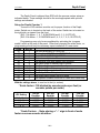
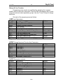
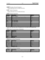
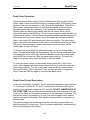
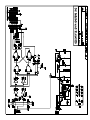
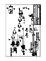
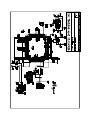
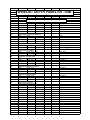
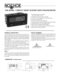
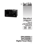
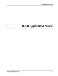
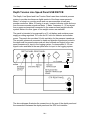
3/27/2002
26-1
Depth Panel
Depth Tension Line Speed Panel USB R9 PCB
The Depth, Line Speed and Line Tension Panel uses three industrial process
meters to provide simultaneous digital readout of the three measurements.
Meter 1 is setup in a counting mode and can accommodate virtually any
encoder resolution. Meter 2 is setup in a rate \ counter indicator mode and runs
from the same encoder signals as Meter 1. Meter 3 senses a 4 - 20 ma signal
from a pressure transducer connected to the measure head weight indicator
system. Meters for other types of line weight sensor are available.
The panel is intended to be powered by a 12 volt battery and contains power
supply providing regulated 12.0 volts and 5.0 volts for indicator and encoder
power. The panel also provides 24 volts excitation for the pressure transducer.
The encoder pulses are converted to depth and direction signals and routed to
the depth and line speed meters and are also buffered and output to the rear
panel connectors for input to the logging system. A retransmitted 4 - 20 ma
signal is also available at the rear panel also for input to the logging system.
The above diagram illustrates the connections to the rear of the depth panel and
the connections between the depth panel and the SDS tool interface.
26-1
3/27/2002
Depth Panel
26-2
The Depth Panel is shipped from SDS with the process meters setup as
indicated below. These settings should be the most appropriate with optional
settings as indicated.
Setup for Depth Counter 1
Two sets of DIP switches must be set for proper function of the Depth
meter. Switch one is located on the back of the meter. Switch two is located on
the right side, as viewed from the front,
(SW-1 On Meter - 1, 4, 7, 8 ON/DOWN and 2, 3, 5, 6 OFF/UP)
(SW-2 On Meter - 1, 2 ON/DOWN and 3, 4, 5, 6, 7, 8, 9, 10 OFF/UP)
Programming may only be accomplished by activating the `program
enable’ switch at the rear of the panel. Other than changing the scale factor, reprogramming should only be necessary upon installation of a new meter.
CODE
ENTRY
41
1
Set unit personality to COUNTER
43
2
Set inputs to COUNT with UP/DOWN Control
44
1
Set to SINGLE EDGE COUNTING
45
2
Set scale multiplier to .01
46
2
Set decimal point and leading zero blanking
51
-2
Set reset mode to manual reset to preset
52
-6
Set Output1 Alarm control to Boundry
53
0.01
Set Output1 Time Delay to minimum
54
3
Set Output2 Termination to Terminate at Reset
55
0.01
Set Output2 Time Delay to minimum
61
4
Set Right hand Dummy Zeros to None
66
2
Set 0perator enabled functions to Reset and Preset only
With the settings above, to read out in feet (or meters)
* Scale factor = 100 divided by encoder pulses per foot (or
encoder pulses per meter)
JP5 Setting
1-2 No Divide
3-4 /2
5-6 /4
7-8 /8
120 ppr
Encoder
0.8333
1.6667
3.3333
6.6666
400 ppr
Encoder
0.2500
0.5000
1.0000
2.0000
600 ppr
Encoder
0.1667
0.3333
0.6666
1.3333
1200 ppr
Encoder
0.0833
0.1666
0.3333
0.6666
*Scale Factors - Note placing a “–“ sign in front of scale
factor reverses encoder direction.
26-2
3/27/2002
Depth Panel
26-3
Setup for Depth Counter 2 / Line Speed
Two sets of DIP switches must be set for proper function of the
Depth/Line Speed meter. Switch one is located on the back of the meter. Switch
two is located on the right side, as viewed from the front,
(SW-1 On Meter - 1, 4, 7, 8 ON/DOWN and 2, 3, 5, 6 OFF/UP)
(SW-2 On Meter – 1, 2,10 ON/DOWN and 3, 4, 5, 6, 7, 8, 9 OFF/UP)
Programming may only be accomplished by activating the `program
enable’ switch at the rear of the panel. Other than changing the scale factor, reprogramming should only be necessary upon installation of a new meter.
CODE
ENTRY
41
1
Set unit personality to RATEMETER/COUNTER
42
3
Set Reset for both Rate and Counter
43
2
Set inputs to COUNT with UP/DOWN Control
44
1
Set to SINGLE EDGE COUNTING
45
2
Set scale multiplier to .01
46
2
Set counter decimal point and leading zero blanking
51
1
Set Output1 to Rate and Output2 to Counter
52
6
Set Rate Alarm control to Boundry
53
0.01
Set Rate Time Delay to minimum
54
3
Set Counter Termination to Terminate at Reset
55
0.01
Set Counter Time Delay to minimum
56
-2
Set Reset Counter to Preset 2
61
4
Set Right hand Dummy Zeros to None
62
1
Set Time Rate to 1 Second
63
1
Set Rate Update Time
64
3
Set Rate Scale Multiplier to 10
65
2
Set Rate decimal point and leading zero blanking
66
2
Set 0perator enabled functions to Reset and Preset only
With the settings above, to read out in feet per minute (or meters per minute)
* Scale factor = 60 divided by encoder pulses per foot (or meter)
JP5 Setting
1-2 No Divide
3-4 /2
5-6 /4
7-8 /8
120 ppr
0.5000
1.0000
2.000
4.0000
400 ppr
0.1500
0.3000
0.6000
1.2000
600 ppr
0.1000
0.2000
0.4000
0.8000
1200 ppr
0.0500
0.1000
0.2000
0.4000
Scale factor for the Depth 2 Counter is the same as the Depth 1
Counter above.
26-3
3/27/2002
26-4
Depth Panel
Setup of Line Tension
Programming may only be accomplished by activating the `program
enable’ switch at the rear of the panel. Press the PAR (Parameters) key to enter
program mode and select parameter groups. Use the F1 and F2 keys to change
selections.
Set each of the program groups as follows:
1-INP Input Parameters
Display
Parameter
Setting
rAn6E
Input Range – 20MA
0.02A
dECPt
Display Resolution – Full Lbs.
0
round
Display Rounding Increment
1
FILtr
Filter Setting
2.0
bAnd
Filter Enable Band
10
PtS
Scaling Points – Use 2 of 16 possible
2
StYLE
Keyboard Entry or Calibration Applied
KEY or APLY
InP 1
Low Input reading in MA
*4.000
dSP 1
Low Display Value in Pounds/Kilos
*0
InP 2
High Input reading in MA
*20.000
dSP 2
High Display Value in Pounds/Kilos
*10000
*Typical values for a 4-20ma sensor and a 0-10000 lb. Calibration.
2-FNC External Input and Function Key Parameters
Display
USr-1
USr-2
USr-3
F1
F2
rSt
Sc-F1
Sc-F2
Parameter
User Input 1
User Input 2
User Input 3
Function Key 1
Function Key 2
Reset Key
Secondary Function Key 1
Secondary Function Key 2
Setting
PLOC
nO
nO
nO
nO
nO
nO
nO
3-LOC Parameter Lockouts
Display
HI
LO
tOt
SP-1
SP-2
SP-3
SP-4
CodE
Parameter
Maximum Reading Display
Minimum Reading Display
Total Reading Display
Setpoint 1 – Entry Enabled
Setpoint 2
Setpoint 3
Setpoint 4
Security Code
26-4
Setting
LOC
LOC
LOC
Ent
LOC
LOC
LOC
0
3/27/2002
26-5
Depth Panel
4-SEC Secondary Function Parameters
These parameters are not used at this time.
5-tOt Totalizer Parameters
These parameters are not used at this time.
6-SPt Setpoint Parameters
Display
Parameter
Setting
SPSEL
Select Setpoint
SP-1
ACt-1
Action for Setpoint – Absolute High
Ab-HI
SP-1
Setpoint Value – Alarm Limit
*1000
HYS-1
Setpoint Hystersis
2
tOn
On Time Delay
0.0
tOF-1
Off Time Delay
0.0
out-1
Output Logic
nor
rSt-1
Reset Action
AUto
Stb-1
Standby Action
NO
Lit-1
Output Panel Light
nor
*Alarm limit value that can be changed from front panel after programming
7-SrL Serial Communications Parameters
Display
bAUd
dAta
PAr
Addr
Abrv
OPt
Parameter
Baud Rate
Word Length
Parity
Address
Abbreviated
Options
Setting
2400
7
Odd
2
nO
nO
8-Out Analog Output Parameters
Display
tYPE
ASIn
An-LO
An-HI
Udt
Parameter
Analog Type
Analog Assignment
Analog Low Scale Value
Analog High Scale Value
Update Time
Setting
4-20
InP
0.00
10000
0.0
9-FCS Factory Service Funtions
Display
Parameter
Setting
Code
Service Access Code – Restore Factory Setup *50
*Normally will show 50. To clear all settings to factory defaults enter code 66.
26-5
3/27/2002
26-6
Depth Panel
Depth Panel Operation
Depth entries and alarm setup points are entered from the key pads of each
meter. Depth1 meter contains the alarm for minimum depth. If the depth counter
becomes less than this minimum, it will activate the depth alarm. Depth2/Line
Speed meter contains the alarm for maximum line speed. If the line speed
becomes greater than this maximum, it will activate the overspeed alarm.
Depth2 meter will display both a depth and the line speed, which can be
selected by pressing the DISP-key. The line tension meter contains the alarm for
maximum line tension. If the line tension becomes greater than this maximum, it
will activate the over tension alarm. Any of the alarms will activate an audible
alarm, front panel LED, and a rear panel external connector. The audio alarm
can be silenced for the duration of the cause of that alarm by pressing the ALM
DIS button. Once the alarm condition has passed, the audio alarm will be
enable again for the next alarm.
To enter a new preset depth on either depth meter, press the P2-key of that
meter. The last preset depth will be displayed. The key directly under each digit
will change the value of that digit. After the desired changes have been made,
press the E-Key to enter the value into preset depth memory. To update the
depth to the preset value, press the R-key to reset the depth.
To enter new alarm values on either depth meter, press the P1-key of that
meter. After changes have been made, press the E-key to enter the value into
preset alarm memory. To enter a new alarm value on the line tension meter,
press the PAR-key. The F1-key and F2-key can then be used to change the
value. Press the PAR-key again to store the new alarm value.
Depth Panel Circuit Description
Power from the battery is routed to the PC board and regulated to approximately
11.5 volts and 5 volts by Q1, D1 and U1 respectively. Encoder power may be
selected from these two voltages by JP1 and JP2. DO NOT JUMPER BOTH AT
THE SAME TIME. The encoder pulses are buffered by the line receiver IC2 and
routed to the depth and line speed meters and to the rear panel connectors. The
line tension sensor is powered by 18 volts from the line weight meter and the
signal routed back to the meter. This signal is retransmitted to a connector on
the rear panel.
The process meters are connected so that they are fully programmable only
when the switch S2 is held open. This is to prevent inadvertent `reprogramming’
from the front panels of the meters.
26-6
3/27/2002
26-7
Depth Panel
Interconnection Cables
The cable to connect the depth panel buffered encoder output to the tool
interface panel has the following connections:
Depth Panel 7 Pin Female
A
B
D
F
G
Interface Panel 7 Pin Male
A
B
D
F
The cable to connect the depth panel encoder input to the depth encoder has
the following connections:
Depth Panel 7 Pin Male
A
B
D
F
G
Depth Encoder 7 Pin Female
A
B
D
F
The cable for the retransmitted line tension from the depth panel to the system
tool interface panel has the following connections:
Depth Panel 5 Pin Female
C
D
E
Interface Panel 5 Pin Male
A
B
E
The cable for the depth panel line tension input to the pressure transducer has
the following connections:
26-7
3/27/2002
Depth Panel 5 Pin Male
D
B
A
E
Depth Panel
26-8
Pressure Transducer
1 (Excite Usually Red)
2 (Signal Usually Black)
Shield
3 (Case)
26-8
WIRELIST DEPTH PANEL R9 - USB
Rear Panel Connectors
10-24-2001
J1
J2
J3
J4
J5
J6
J7
J8
DC Power In
J1-A
J10-1
J1-B
SW2-2/5
GND LUG
+12V Battery
Chassis Ground
Line Weight Input from Transducer
J2-A
J2-E
J2-B
J11-3
J2-D
J11-4
J2-E
J5-F
J2-A
GND
4-20ma Signal
+12V Excite
GND
Line Weight Retransmit to System
J3-C
J11-10
J3-D
J11-9
PAX Analog 19 -(0-20)Out
PAX Analog 18 +(0-20)Out
External Lamp or Alarm
J4-A
PCB_J2-2
J4-B
PCB_J9-8
+12V Reg
External Lamp
BZ+
Quadrature Encoder Input
J5-A
PCB_J3-1
J5-B
PCB_J3-2
J5-D
PCB_J3-3
J5-F
J2-E
J6-F
Encoder A
Encoder B
Encoder Power
GND
Buffered Quadrature to System
J6-A
PCB_J1-4
J6-B
PCB_J1-5
J6-F
J5-F
J7-F
Buffered A
Buffered B
GND
Buffered Quadrature Spare
J7-A
PCB_J1-2
J7-B
PCB_J1-3
J7-F
J6-F
GND LUG
Buffered A
Buffered B
GND
USB Port to Computer
Connected Directly to Board
J10
P10
J11
P11
PAX
Front Panel Controls
J10-1
J1-A
J10-2
BZ+
J10-3
PCB_J9-5
J10-4
PCB_J2-4
J10-5
PCB_J8-2
J10-6
GND LUG
+12V Battery
Reg 12V - LED
Mute Switch
Switched 12 Volt
Led Control
GND
Front Panel Controls
P10-1
F1-2
P10-2
LED RED
P10-3
SW4-2
P10-4
SW1-1
P10-5
LED WHT
P10-6
SW4-1
+12V Battery
Reg 12V - LED
Mute Switch
Switched 12 Volt
Led Control
GND
Line Tension Meter
J11-1
PCB_J2-1
J11-2
GND LUG
J11-3
J2-B
J11-4
J2-D
J11-5
SW2-3
J11-6
PCB_J4-1
J11-7
PCB_J4-2
J11-8
GND LUG
J11-9
J3-D
J11-10
J3-C
J11-11
GND LUG
J11-12
PCB_J9-4
Line Tension Meter
P11-1
PAX-1
P11-2
PAX-2
P11-3
PAX-4
P11-4
PAX-6
P11-5
PAX-8
P11-6
PAX-12
P11-7
PAX-13
P11-8
PAX-14
P11-9
PAX-18
P11-10
PAX-19
P11-11
PAX-20
P11-12
PAX-21
Line Tension Meter
PAX-1
P11-1
PAX-2
PAX-7
PAX-4
P11-3
PAX-6
P11-4
PAX-7
PAX-2
PAX-8
P11-5
PAX-12
P11-6
PAX-13
P11-7
PAX-14
P11-8
PAX-18
P11-9
PAX-19
P11-10
PAX-20
P11-11
PAX-21
P11-12
Reg 12 Volt
GND
4-20ma Signal
+12V Excite
PGM Mode
DR+
DRGND
PAX Analog 18 +(0-20)Out
PAX Analog 19 -(0-20)Out
GND
TNS ALM
Reg 12 Volt
GND
4-20ma Signal
+12V Excite
PGM Mode
DR+
DRGND
+(0-20)Out
-(0-20)Out
GND
TNS ALM
P11-2
Reg 12 Volt
GND
4-20ma Signal
+12V Excite
GND
PGM Mode
DR+
DRGND
+(0-20)Out
-(0-20)Out
GND
TNS ALM
Depth and Line Speed
DP_TBA DEPTH Meter TBA - Control
DP_TBA-3 LS_TBA-3
DP_TBA-5 DP_TBA-8
DP_TBA-7 LS_TBA-7
DP_TBA-8 DP_TBA-10
DP_TBA-9 PCB_J9-2
DP_TBA-10 DP_TBA-8
DP_TBA-11 PCB_J1-1
DP_TBC Depth Meter TBC - Depth
PCB_J2-1
DP_TBC-5
SW2-6
LS_TBC-1
+12V
GND
PGM Mode
GND
Depth ALM
GND
Reset
DP_TBC-1 DP_TBC-5 PCB_J2-3
DP_TBC-2 LS_TBC-2 PCB_J1-7
DP_TBC-3 LS_TBC-3 PCB_J1-6
DP_TBC-5 DP_TBA-5 DP_TBC-1
DP_TBD Depth Meter TBD - Communications
DP_TBD-1 PCB_J6-2
DP_TBD-3 DP_TBD-5
DP_TBD-4 LS_TBD-5
DP_TBD-5 DP_TBD-3
DP_TBD-6 LS_TBD-7
DP_TBD-7 LS_TBD-3
LS_TBA Line Speed Meter TBA - Control
LS_TBA-3 DP_TBA-3
LS_TBA-5 LS_TBA-8 LS_TBC-5
LS_TBA-7 DP_TBA-7
LS_TBA-8 LS_TBA-10 LS_TBA-5
LS_TBA-9 PCB_J9-3
LS_TBA-10 LS_TBA-8
LS_TBC Line Speed Meter TBC - Depth
GND
DIR
PPR
GND
LS_TBC-1 LS_TBC-5 DP_TBA-10
LS_TBC-2 DP_TBC-2
LS_TBC-3 DP_TBC-3
LS_TBC-5 LS_TBA-5 LS_TBC-1
LS_TBD Line Speed Meter TBD - Communications
LS_TBD-1 PCB_J6-4
LS_TBD-3 DP_TBD-7
LS_TBD-4 PCB_J6-1
LS_TBD-5 DP_TBD-4
LS_TBD-6 PCB_J6-3
LS_TBD-7 DP_TBD-6
GND
DIR
PPR
GND
Meter Communications
Meter Communications
Meter Communications
Meter Communications
Meter Communications
Meter Communications
+12V
GND
PGM Mode
GND
SPD ALM
GND
Meter Communications
Meter Communications
Meter Communications
Meter Communications
Meter Communications
Meter Communications
PC Board Connectors
PCB_J1 Encoder Connections
PCB_J2
PCB_J1-1 DP_TBA-11
PCB_J1-2 J7-A
PCB_J1-3 J7-B
PCB_J1-4 J6-A
PCB_J1-5 J6-B
PCB_J1-6 DP_TBC-3
PCB_J1-7 DP_TBC-2
PCB_J1-9 PCB_J3-4 GND LUG
12 Volt Power Distribution
PCB_J2-1 DP_TBA-3 J11-1
PCB_J2-2 J4-A
PCB_J2-3 DP_TBC-1 GND LUG
PCB_J2-4 J10-4
Reset
Buffered A
Buffered B
Buffered A
Buffered B
PPR
DIR
GND
PCB_J3-1
PCB_J3-2
PCB_J3-3
PCB_J3-4
J5-A
J5-B
J5-D
PCB_J1-9
Encoder A
Encoder B
Encoder Power
GND
PCB_J4-1
PCB_J4-2
J11-6
J11-7
DR+
DR-
PCB_J6-1
PCB_J6-2
PCB_J6-3
PCB_J6-4
LS_TBD-4
DP_TBD-1
LS_TBD-6
LS_TBD-1
Meter Communications
Meter Communications
Meter Communications
Meter Communications
PCB_J8-1
PCB_J8-2
J10-5
GND
Led Control
PCB_J9-1
PCB_J9-2
PCB_J9-3
PCB_J9-4
PCB_J9-5
PCB_J9-8
PCB_J9-9
DP_TBA-9
LS_TBA-9
J11-12
J10-3
J4-B
BZ-
Depth ALM
SPD ALM
TNS ALM
Mute Switch
External Lamp
Buzz Control
Reg 12 Volt
Reg 12V - LED & Buzzer
GND
Switched 12 Volt
PCB_J3
PCB_J4
PCB_J6
PCB_J8
PCB_J9
Misc. Items
F1
SW1
SW2
SW4
LED
Fuse
F1-2
SW1-2
F1-2
P10-1
Power on/off
SW1-1
P10-4
SW1-2
F1-1
Program Mode
SW2-2
SW2-5
SW2-3
J11-5
SW2-5
SW2-2
SW2-6
DP_TBA-7
Mute Button
SW4-1
P10-6
SW4-2
P10-3
+12V Battery
Fused +12V
Switched 12 Volt
Fused +12V
J1-B
GND
PGM Mode
GND
PGM Mode
J1-B
GND
Mute Switch
Alarm Indicator
RED
P10-2
WHT
P10-5
Reg 12V - LED
Led Control
BUZZER
BZ+
BZ-
J4-A
PCB_J9-9
J10-2
PCB_J2-3
J10-6
PCB_J1-9
J11-2
J1-B
J11-8
Reg +12
Buzz Control
GND LUG
J7-F
J11-11