1
2009 Discovery Telecom Technologies
2
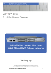
VoIP All™ Series 4 Channel Gateway
Utilize VoIP to connect directly to
GSM Ι CDMA Ι UMTS cellular networks
For additional assistance please contact us: Tel.: +1801 7900348,
+7495 7907870
Skype: discoverytelecom
Mail: [email protected]
Site: www.discoverytelecom.ru
VoIP2All™ Series: 4 Channel Gateway User Manual 1
2009
DTT USER MANUAL
Usage Warnings High voltage transients, surges, and other power irregularities can cause extensive damage to your device. It is the user's responsibility to provide a power protection system. It is the user's responsibility to install, operate, and maintain the system in according to all local and internationally applicable codes, regulations, and safety measures.
Trademarks and Patents Copyright © 1997‐2009 Discovery Telecom Ltd. All rights reserved. The reuse or reproduction of any of the information, design or layout contained in this manual or in our web site without the permission of DTT Ltd. is prohibited. All trademarks, patents and copyrights apply.
General Notes Without a notice and without obligation, the contents of this manual may be revised to incorporate changes and improvements. Every effort has been made to ensure that the information is complete and accurate at the time of publication. Nevertheless, DTT cannot be held responsible for errors or omissions. The screen snapshots in this manual may have older version labels than your delivered package version.
Dear Customer, We thank you for purchasing DTT ’s VoIP2ALL Gateway. All our products are developed and produced by experienced engineers, who aspire to achieve customer satisfaction, utility value and reliability of products. The information in this manual has been compiled and checked for accuracy by DTT . It however does not constitute as a warranty of performance. We hope you enjoy our product and always appreciate any comments you may have. This will VoIP2All™ Series: 4 Channel Gateway User Manual 2
2009
DTT VoIP2All USER MANUAL
enable us to improve our products and our personal service and technical support that strive to provide for every customer. Warranty Policy Discovery Telecom Technologies Ltd (DTT) guarantees its products against defects in materials and workmanship for a period of 24 months from date of purchase. Any damage caused by external causes, including problems with electrical power, servicing not authorized by DTT, negligent installation or operation, failure to follow documented procedures, abuse, or general misuse of the product is not covered by the warranty. Custom configured products are nonrefundable. DTT makes no express warranties except those stated in this paragraph and in the applicable warranty statements for specific products in effect on the date of invoice. To request warranty service, you must call DTT +1801 7900348, e‐mail: [email protected], or complete the online RMA Request form within the warranty period with a description of the problem. If warranty service is required, DTT will issue a Return Material Authorization (RMA) Number. You must ship the defective product back to DTT during the warranty period in its original or equivalent packaging, prepay shipping charges, and insure the shipment or accept the risk of loss or damage during shipment. DTT will ship the repaired or replacement products to you. DTT reserves the right to modify its warranty at any time, in its sole discretion. All software is provided subject to the license agreement that is part of the package. Customer agrees that it will be bound by the license agreement once the package is opened or its seal is broken. DTT does not warrant any software under this Agreement. Warranties, if any, for software are contained in the license agreement that governs its purchase and use. Table of Contents Geting Started ........................................................................................................................ 6 Check Your Package Items ...................................................................................................... 7 The 4 Channel VoIP2ALL Gateway Solution Overview .............................................................. 8 Chapter 1: Installing SIM Cards and Connecting the Cables ...................................................... 9 Chapter 1.1: Hardware overview ...................................................................................... 9 Chapter 1.2: Installing the SIM Cards in a Cellolar Card ................................................... 10 Chapter 1.3: Installing the SIM Cards in a SIM Server Card .............................................. 10 Chapter 1.4: Connecting the Cables ............................................................................... 10 Chapter 2: Installing the Manager Application ........................................................................ 11 Chapter 2.1: Install the VoIP2ALL Management Application into an MS‐Windows PC ...... 11 VoIP2All™ Series: 4 Channel Gateway User Manual 3
2009
DTT USER MANUAL
Chapter 3: VoIP2ALL Basic Operations ................................................................................... 11 Chapter 3.1: Connecting the Menagement software to the VoIP2ALL ............................ 12 Chapter 3.2: Setting Up the clock .................................................................................. 12 Chapter 3.3: Changing the IP Adress of the gateway ....................................................... 13 Chapter 3.4: Setting up the Internal SIP Server ............................................................... 13 Chapter 3.5: Working with Local SIM .............................................................................. 13 Chapter 3.6: Assigning a prefix to a port ........................................................................ 14 Chapter 3.7: Dailing ...................................................................................................... 14 Chapter 3.8: Connecting IP PBX to the gateway .............................................................. 15 Chapter 3.9: Connecting the Gateway to IP PBX ............................................................. 15 Chapter 3.10: Connecting to SIM Server ........................................................................ 16 Chapter 3.11: Assigning a SIM to work at a specific time ................................................. 17 Chapter 4: VoIP Settings ....................................................................................................... 18 Chapter 4.1: General Settings ....................................................................................... 18 Chapter 4.2: Internal SIP Server ..................................................................................... 19 Chapter 4.3: Tones Levels .............................................................................................. 21 Chapter 4.4: SIP Server Settings .................................................................................... 22 Chapter 4.5: IP Restrictions ............................................................................................ 24 Chapter 5: System Settings ................................................................................................... 24 Chapter 5.1: General Settings ........................................................................................ 24 Chapter 5.2: FXO Settings ............................................................................................. 25 Chapter 5.3: Calls Reports ............................................................................................ 26 Chapter 6: Ports Settings ...................................................................................................... 26 Chapter 6.1: General Settings ....................................................................................... 26 Chapter 6.2: Time Table ................................................................................................. 27 Chapter 6.3: Prefixes ..................................................................................................... 28 Chapter 6.4: Local SIM Settings ..................................................................................... 30 Chapter 6.5: Working with Local SIM ............................................................................. 30 Chapter 7: SIM Server ............................................................................................................. 31 Chapter 7.1: Connecting to SIM Server .......................................................................... 32 Chapter 7.2: SIM Server Settings .................................................................................... 32 Chapter 8: Users.................................................................................................................... 32 Chapter 8.1: Adding a User ............................................................................................. 33 Chapter 8.2: User Capabiliteis ........................................................................................ 34 Chapter 9: Monitoring Calls .................................................................................................... 35 Chapter 9.1: The Port Control Window ............................................................................ 35 Chapter 9.2: SMS ........................................................................................................... 37 Apendix A: COM Port ............................................................................................................ 40 VoIP2All™ Series: 4 Channel Gateway User Manual 4
2009
DTT VoIP2All USER MANUAL
Getting Started The DTT team is glad you have chosen to use the DTT’s VoIP2ALL Gateway to fulfill your needs. We will do our best to make your installation efforts and day‐to‐day configuration and monitoring tasks pleasant. We wish you smooth operation, and hope you enjoy greatly saving on your office / mobile phone calls. This chapter is your map for installation, configuration and monitoring tasks and includes a short explanation detailing each stage. It also includes references for more elaborated explanations, drawings and examples in following chapters. The following is a list of recommended tasks, Including mandatory and optional tasks that may or may not be required for your current needs. It is advised to use the following menu as your check‐up ‘To‐Do‐List‘ Mandatory • Check package items delivered in your package *Refer to the “Check your Package Items” chapter to view a list of all items, which should be included in your package. • Installation and Connections o Install SIM Cards o Install Antennas o Install LAN cable *Refer to “Chapter 1: SIM Cards Installation and Cables Connecting” for specific and detailed guidelines. Install the PC management application Follow the ‘Quick Installation Guide’ included in you package to install the MS‐Windows Management Application on the PC/Laptop allocated for the system management. Use the provided CD. * Refer to “Chapter 2: Installing the Manager Application” for further information. The Quick Installation guide is available for download at our website. •
General Configurations In order to operate the system, mandatory basic setup steps should be performed by using the LAN. System Configuration Use the LAN connection and VoIP2ALL Management MS‐Windows application. You can use this method for later day‐to‐day management for monitoring and reports of the VoIP2ALL activity. The gateway system via IP is highly recommended as you can have the management done remotely from the system via internet connection. VoIP2All™ Series: 4 Channel Gateway User Manual 5
2009
DTT USER MANUAL
Check Your Package Items Please verify that your package contains the following components before installation: •
•
Main Hardware Device ‐ The VoIP2ALL Gateway 110/220V 50‐60Hz Power Supply. •
•
•
Software Installation CD ‐ Gateway Manager CD for MS‐Windows Management Application. Includes the User Manual file and additional auxiliary utilities. GSM Antenna LAN Connection Cable •
TCP/IP Cross Cable (Red Cable). Facilitates gateway connection directly to the PC Network Interface Card. •
RS‐232 Serial PC Comport connection cable (RJ‐45 to RS‐232 COM). Facilitates debugging and direct access to the configuration files. Will be referred as ‘Com Cable’ in this manual. •
Quick Installation Guide – for brief installation explanations. VoIP2All™ Series: 4 Channel Gateway User Manual 6
2009
DTT VoIP2All USER MANUAL
The 4 Channel VoIP2ALL Gateway Solution Overview The 4 Channel VoIP2ALL gateway that will be referred as the VoIP2ALL in short, can connect VoIP calls to cellular networks (CDMA GSM UMTS). The VoIP2ALL has a built in SIP Server that can register up to 32 VoIP clients. The VoIP2ALL can connect each of these VoIP clients to the cellular network directly, therefore completely bypassing the local landline telephone company. The VoIP2ALL has up to 4 SIM ports and a VoIP SIP Server. The VoIP2ALL can connect a VoIP Client to another VoIP Client. You are also able to call from one of the cellular ports and to another cellular port. Each cellular port has one SIM (local sim) and the ability to work with SIM from any VoIP2ALL SIM Server. The VoIP2ALL is able to connect to up to 20 external SIM Servers. Each cellular port can be programmed to work with any of the SIMs in the SIM Servers at any given time. The Gateway may be configured to direct calls through the most economic SIM. *According to your service providers’ rate plan. VoIP2All™ Series: 4 Channel Gateway User Manual 7
2009
DTT USER MANUAL
Basic Terms •
•
•
•
•
•
•
•
•
•
•
•
•
•
•
•
Gateway – A VoIP2ALL unit with cellular ports. SIM Server ‐ A VoIP2ALL series unit with a SIM Server program ‐ containing SIM cards and no cellular cards. Internal SIM Server – A SIM Server program that runs on a gateway allowing access to SIM cards in the gateway. External SIM Server – A SIM Server program that runs on an external SIM Server or another Gateway allowing access to SIM cards in the external SIM Server. Master card – The part that controls the operation of the VoIP2ALL. (Contains a DSP processor with a linux based operating system.) Slave Card – The part in the gateway that controll the cellular ports (modules). VoIP – A protocol of transmitting voice calls on ethernet networks. SIP – A protocol of registering VoIP clients and making VoIP calls. SIP Server – A virtual PBX that can register and connect SIP phones. SIP Account – A user name and password which is given to a SIP phone to register with. SIP Registration – The proccess of the initial connection to the SIP Server with the SIP acount. SIP Client – A SIP phone that is registered in a SIP Server. Internal SIP Server – The SIP Server that is built in the gateway. SIM Registeration – The activation of the SIM in a cellular network. Only when the SIM is registered you can make calls. Local SIM – A SIM on slave card. Virtual SIM – A SIM from a SIM Server. VoIP2All™ Series: 4 Channel Gateway User Manual 8
2009
DTT VoIP2All USER MANUAL
Chapter 1: Installing SIM Cards & Connecting Cables Chapter 1.1: Hardeware Overview The gateway consists from four main parts: • The Master – Contains a AudioCodes™ DSP processor with a Linux based operating system. Using a Linux operating system run the ‘v2g’ program that operates the gateway. •
The Slave – Contains 4 cellular ports. Each port has one local SIM. Each card has one antenna connection for all 4 ports. The card is controled by two programble processors. Chapter 1.2: Installing the SIM Cards in the Cellular Cards Insert the SIM cards into the VoIP2ALL as follows: • Each cellular port has 1 local SIM. • On the bottom of the each cellular port, there are labeled slots for the local SIMs. • Position the SIM in the slots so the SIM metal contacts face upward and the snubbed triangle inwards into the device. • Gently insert the SIM until you hear a click. • The SIM is now in place. Note: To extract the SIMs you need to push and release the SIM, the SIM will be released from the switch, and then pull it out. Chapter 1.3: Connecting the Cables There are two sets of LAN and COM connectors on the master card marked ST1 and ST2. The VoIP2ALL currently use only the ST1 connectors in the left. (ST2 connectors in the right are currently not in use.) • LAN cable ‐ The LAN cable is used to connect the system to the internet network. Connect the LAN line to the left RJ‐45 marked LAN (the right RJ‐45 marked LAN is not in use). Antenna – Connect one antenna for all the four channels. Position the antennas at least •
20 centimeters apart and more then 1.5 meters from the VoIP2ALL. • Power Supply ‐ Connect the power supply from your 110‐240V 50‐60Hz power outlet to the VoIP2ALL Gateway power connector. • Com Cable – Connect the Com Cable from the PC RS‐232 comport to the left RJ‐45 marked COM (the right RJ‐45 marked COM is not in use). The com connection is not essential for day to day use. VoIP2All™ Series: 4 Channel Gateway User Manual 9
2009
DTT USER MANUAL
Chapter 2: Installing the Manager Application Before operation, configuration settings must be applied to the VoIP2ALL Gateway. Configuration is done on an auxiliary computer by using the VoIP2ALL Management MS‐
Windows Application provided for MS‐Windows operating system. Chapter 2.1: Install the VoIP2ALL Management Software on a MS‐Windows PC 1. Insert the VoIP2ALL Management Installation CD into the CD drive of the PC. 2. Through MS Explorer, navigate to the installation CD drive. 3. Double‐click ‘setup.exe’ to install the Management Application. 4. Click Next. 5. The ‘Setup Type’ window will open. 6. Select Complete and click next. 7. Click Install. The VoIP2ALL Management application installs itself. Wait until a ‘Completion’ message appears. Chapter 3: The VoIP2ALL Basic Operations After installing the Management application, launch the program from the icon located on your desktop ‘VoIP2All**.exe’ to define the connection between the PC and the VoIP2ALL, described below. Launch the VoIP2ALL Management by pressing on your PC desktop, or: a. Start>Programs>DTT‐>VoIP2ALL Management. The VoIP2ALL management application window should now open, pictured below: Chapter 3.1: Connecting the Management Software to the VoIP2ALL VoIP2All™ Series: 4 Channel Gateway User Manual 10
2009
DTT VoIP2All USER MANUAL
1. Press in the toolbar. The Selected Connection window will open. 2. Enter in the 'Host Address' the IP Address of the VoIP2ALL Gateway (The default IP Address is 10.16.2.245), as pictured. 3. Enter in the 'Port Number' the port of the VoIP2ALL gateway (The default port is 2007). 4. Enter in the 'Password' the password of the VoIP2ALL gateway (The default password is admin). 5. Press OK to connect. 2
Note: You must wait 30 seconds after connecting the power to the VoIP
ALL gateway for the initialization process to end before connecting with the PC Management. Note: If you can't remember the IP Address see Appendix A: Com Port. Chapter 3.2: Setting Up the Clock 1.
2.
3.
4.
5.
Go to 'System' in the tool bar. Select in the Date box the date of the VoIP2ALL gateway. Enter in the Time box the time of the VoIP2ALL gateway. Select in the Date Format how to display the date, (Day:Month:Year) or (Year:Month:Day). Press Save to change the time and date. Chapter 3.3: Changing the IP Address of the Gateway 1.
2.
3.
4.
5.
Open the VoIP window; select the ‘General’ tab. In the ‘IP Address’ box enter the new IP address for the gateway. Press Save. Disconnect from the gateway. Restart the gateway, wait 30 seconds for initialization, connect with the new IP address. Chapter 3.4: Internal SIP Server The Gateway has an internal SIP Server that is able to register up to 32 SIP clients. This SIP client can be: a VoIP phone, or external SIP Servers or IP PBX. VoIP2All™ Series: 4 Channel Gateway User Manual 11
2009
DTT USER MANUAL
By default the Internal SIP Server works without authentication, you can register with no password and you can choose any user name. The user name should be a number. Registering a VoIP phone in the Internal SIP Server 1. Open the configuration page of the SIP phone. 2. Set up the following registration parameters: • The "SIP Server IP Address" ‐ the IP address of the gateway. • The "SIP User ID" ‐ the chosen number for this extension (any number). • The ‘Authentication Password’ – may be left empty. 3. Save settings. 4. Register with the new account. 5. Via the VoIP2ALL PC management, open the 'SIP Status' window to see the SIP phone registered. Chapter 3.5: Working with a local SIM For each cellular port there is one dedicated local SIM. This SIM can work only with that cellular port. There are two basic modes of working with the local SIM, ‘active by default’ or ‘work by timetable.’ Setting the Local SIM to be active by default In this mode the local SIM will register in the cellular network automatically when inserted in the SIM socket. 1. Open the 'ports' window. 2. On the left you will see list of all the ports, select 'General.' 3. Set the 'Default SIM' parameter to 'Enable.' 4. Insert the SIM to the cellular port’s local SIM socket. 5. Open the 'Monitor' to view the status of the cellular ports. Fig: Cellular Port monitor When the SIM is registered correctly ‐ the monitor window will change to a light green color and the Net and SIM indicator will change from yellow to green. Chapter 3.6: Assigning a Prefix to a Port VoIP2All™ Series: 4 Channel Gateway User Manual 12
2009
DTT VoIP2All USER MANUAL
Using the basic setting, an incoming call from a port will receive a dial tone. The user may then dial a number, the gateway will route the call according to the prefix of the dialed number. To assign prefix to a port: 1. Open the 'Ports' window. 2. Select a port from the list on the left. 3. Press the 'Prefixes' tab to see the prefix table of the port. 4. Enter the Prefixes for this port. When a dialed number starts with one of the prefixes in the list, the call will automatically route to this port. If the prefix of a port is ‘*’, then all the calls that do not conform to the other port’s will be routed through this port. • If two or more ports have the same prefix then the gateway will rotate calls between the ports. 5. In the ‘Remove Prefix’ box select how many digits to remove from the beginning of the dialed number. 6. In the ‘Add Prefix’ box enter the digits to be added at the beginning of the number. 7. Press 'Save' to activate all changes. Chapter 3.7: Dialing Dialing from a mobile phone to a VoIP extension To call a VoIP extension from a mobile phone through Port 1 with the default prefix settings: • Dial the number of the SIM card in port 1. • Hear a dial tone. • Dial 9 plus the VoIP extension number (9 is the default prefix setting for VoIP) • i.e. 9100 (when 100 is the voip extension) • The call will route to the VoIP extension. Dialing from a VoIP extension to a mobile phone To call from a VoIP extension to mobile phone with the default prefix settings: • Pick up the VoIP extension and hear a dial tone. • Dial the GSM mobile number. • The call will route to Mobile phone through the first available cellular port. Note: If the mobile number start with 9, then you must setup the prefix of the VoIP to a different number, otherwise the call will route to the VoIP. Dialing through a specific port To call a mobile phone through a pre‐defined specific port: • Set the 'Prefix' of this port to certain number (6). • Set the 'Remove Prefix' to the number of digits in that prefix (i.e. 1). • Save the prefixes settings. • Pick up the VoIP extension and hear a dial tone. • Dial the prefix (i.e. 6) and the mobile number. i.e. 605555555 (when 05555555 is the mobile number) VoIP2All™ Series: 4 Channel Gateway User Manual 13
2009
DTT USER MANUAL
•
The call will route through this port Chapter 3.8: Connecting IP PBX to the Gateway To receive calls from IP PBX or any external SIP Server, you need to register the IP PBX in the VoIP2ALL gateway internal SIP Server. Registering external SIP Server in the gateway internal SIP Server The registration is performed in the external SIP Server configuration. The procedure is the same as in registering with VoIP Phone; see "Chapter 3.4 Internal SIP Server". 1. Open the "SIP Registration" in the external SIP Server or IP PBX. 2. Set up the registration with these parameters: • The "SIP Server IP Address" ‐ the IP address of the gateway. • The "SIP User ID" ‐ the chosen number for this extension. • The ‘Authentication Password’ ‐ when working with authentication. 3. Save the registration settings. 4. Register the new account. Verify the registration by checking the sip status window Dialing from the IP PBX When calling from an IP PBX to cellular via the gateway. The number of the mobile phone needs to be sent in the INVITE message of the SIP. To set up the dialing from the IP PBX to a GSM mobile phone through the gateway: • Dial from the PBX to the gateway. • view the 'Monitor' of the gateway ‐ check the number that the gateway dialed (i.e. (39)0545555555). • Go to the prefix table of this port. • Setup the prefix of this port (i.e. 39). • Setup the 'Remove Prefix' to the number of digits You wish to remove (2 digits) • Dial from the PBX the number 390545555555. • The call will now be routed through this port to the mobile phone by removing the prefix (39) and calling the desired cellular number 0545555555 Chapter 3.9: Connecting the Gateway to IP PBX To send calls to the IP PBX or any SIP Server you must register the Gateway in the external SIP Server. Registering the Gateway in the external SIP Server VoIP2All™ Series: 4 Channel Gateway User Manual 14
2009
DTT VoIP2All USER MANUAL
The VoIP2ALL’s internal SIP Server can connect to an external SIP Server by adding a host in the ‘Hosts’ table. When the SIP Servers are connected you will be able to make calls from the Gateway to the Host SIP. 1. Receive a SIP account from the external SIP Server. 2. Open the SIP tab in the VoIP window. 3. Add a new Host to the list with the SIP account’s information: •
•
•
•
•
•
The 'Name' is the chosen name for this host connection. The 'IP Address' is the SIP Server IP address or desired registration name. The 'Port' is the number of the SIP Server port (the default is 5060). The 'User' is the user number or name. The 'Secret' is the authentication password of the SIP account. The 'Register' box, check it to register in the SIP. 4. Click on the next line in the table and press "Save". 5. Press the ‘Register Host’ button, to register the host in the external SIP Server. 6. After a few seconds, Press "Refresh". If the registration succeeded, the Status will show ‘Reg’. If registration failed, it will show 'Not Reg'. 7. Go to the ‘Prefixes’ window and define a prefix for this host. Dialing to the IP PBX To call from a GSM mobile phone through Gateway to extension in the IP PBX • Go to the 'Ports' window. • From the ports list, select this Host. • Setup the prefix of the host to the prefix of the PBX extensions (i.e. if all the PBX extensions start with the digit 1, then the prefix of the host will be 1). • Setup the 'Remove Prefix' to 0. • Dial the number of the SIM card in port 1. • Hear a dial tone. • Dial the PBX extension number. • The Gateway will recognize the prefix of the Host (i.e. 1) and the call will be routed to the IP PBX. Chapter 3.10: Connecting to a SIM Server The connection to the SIM Servers is done via the ‘Virtual SIM’ window. The VoIP2ALL Gateway can connect to SIMs in both the internal and external SIM Servers. An external SIM Server could be a SIM Server unit or another Gateway with a SIM Server program. When the Gateway needs to register a SIM from the SIM Server, it will connect to the SIM Server with port 2009 and will request the data of that SIM. All the information will be passed through port 2008. VoIP2All™ Series: 4 Channel Gateway User Manual 15
2009
DTT USER MANUAL
The connection between the Gateway and the SIM Server is limited to the time that the Gateway is registered with a SIM from the SIM Server. When the SIM server is operating behind a firewall, ports 2008 and 2009 should be open for the operation of the SIM server. Port 2007 should be open for remote access with the PC. The Gateway may connect to an unlimited amount of SIMs in the SIM Server. To view the SIM's that are in the SIM server ‘Add’ the SIM Server to the 'SIM Servers List'. Viewing the SIM's in a SIM Server 1. Go to the 'SIM Servers List'. 2. Enter the IP address of the SIM Server. 3. Enter the port of the SIM Server; the default port for a VoIP2ALL SIM Server is 2009. 4. Press the ‘Save List’ button. Press the ‘Synchronization’ button. The gateway will connect to all SIM Servers and will read all the SIM lists. In the 'SIM Server Setting' list you will see all the SIMs from the SIM Servers. The list is arranged accordingly to SIM servers. Each SIM Server has cards starting from card1 to card8. Each card has the SIMs from 1 to 32 according to their location on the card. *Note: These tables are saved in the PC software files only; it is not saved on the Gateway. So if you connect from another PC it will not automatically appear. Chapter 3.11: Assigning a SIM to Work in a Port at a Specific Time On the 'Available SIMs' list, the local SIM (L1) and all the SIMs from the SIM Servers are visible. Each SIM Server SIM listing contains its location on the SIM Server and its IMSI number. To assign a SIM to work at a specific time: 1. Go to the 'Ports' window. 2. Select a port from the list of the ports on the left. 3. Open the 'Time Table' tab. 4. In the ‘Type’ category, select the form of the timetable: monthly or weekly. 5. In the ‘Swapping Type’ category, select ‘time table.’ 6. Select a SIM from the list of available SIMs at the top. 7. The top row of the Timetable represents dates and the left column represents hours. 8. Each time slot is for a period of one hour. 9. Left click will select the SIM for this time slot and mark it with it’s corresponding number. 10. You can mark a range of time by dragging the mouse while holding the left click. 11. To un‐select time slots simply click on it again. 12. You are unable to choose a SIM that is already in use at that time in another port on the Gateway. 13. After setting all the needed SIMs press 'Save'. 14. After setting the needed changes on all the ports press 'apply' to activate. VoIP2All™ Series: 4 Channel Gateway User Manual 16
2009
DTT VoIP2All USER MANUAL
SIM Swapping Limitation Time Slot – is a continuous time slot for a SIM to work in the timetable. There is a firmware limitation of 30 Time Slots for each port. Chapter 4: VoIP Settings Press to open the VoIP setup window. Chapter 4.1: General Settings Press the General tab to see: IP Settings •
•
•
•
•
‘IP Address' ‐ Is the IP address of the Gateway. By default it is 10.16.2.245. 'Default Gateway' – When working behind a firewall, you must setup 'Default Gateway' for the Gateway to be able to access the WAN, usually it Is the IP address of the Router that the Gateway work behind. ‘Subnet Mask’ ‐ When working behind a firewall, you must setup 'Subnet Mask'. ‘Port' ‐ IP port of the VoIP2ALL. Used for connecting with the PC management. Default setting it is 2007. 'DNS' – When working behind a firewall, if you need to connect to a external SIP Server with a name (not IP address), then you must setup the 'DNS', usually it Is the IP address of the Router that the Gateway work behind. Dialing Settings VoIP2All™ Series: 4 Channel Gateway User Manual 17
2009
DTT USER MANUAL
• ‘Wait for Dialing’ ‐ The time, in seconds, from the start of the dial tone the VoIP2ALL will wait for the first digit to be dialed. After that time the VoIP2ALL will close the voice channel. • ‘Last Digit Timeout’ ‐ The time, in seconds, the VoIP2ALL will wait between the last digit dialed and the calling of that number. • ‘No Replay Timeout’ ‐ The number of seconds with no answer the Gateway will wait before calling the next number (In Priority or Cyclic mode). • ‘DISA’ ‐ Is the number of seconds each DISA number will stay in memory. • ‘Debug Level’ ‐ Is the amount of detail to be shown on the Debug Screen. This level usually should be set at 2, so the Gateway will not send unnecessary debug lines to PC software. • When done setting, press ‘Save’ to activate all the changes. • 'Restart Call' – When enabled allows consecutive VoIP calls. Before the end of a call from the GSM to VoIP, press * to receive a dial tone that enables you to call another VoIP number. Changing the IP Address of the Gateway The VoIP2ALL Gateway is connected to the net via one IP Address allotted to 3 Ports: 2007 (Gateway’s IP Port), 2008 (SIMs Port), and 2009 (Internal SIM Server Port). Changing the VoIP2ALL’s IP address will change the IP address for the Gateway and the internal SIM Server. 1. Connect to the VoIP2ALL Gateway with the current IP address port 2007. 2. Open the VoIP window; select the ‘General’ tab. 3. In the ‘IP Address’ box enter the new IP address for the Gateway. 4. If needed, set up the Default Gateway and the Subnet Mask. 5. Press Save. 6. Disconnect from the Gateway. 7. Restart the Gateway, wait 30 seconds for initialization, connect with new IP address. Chapter 4.2: Internal SIP Server The Gateway has an internal SIP Server that can register up to 32 SIP clients. These SIP clients can be VoIP phones or SIP Servers. In the window below, a list of all the SIP Accounts that are registered in the SIP Server is available. Press the ‘Sip Status’ tab to access: Press Refresh to monitor the SIP accounts that are registered in the VoIP2ALL Gateway.
VoIP2All™ Series: 4 Channel Gateway User Manual 18
2009
DTT VoIP2All USER MANUAL
• The User ID is an identification number in the Sip Server for this account. • The User Name is the sip account number. • The User IP is the IP Address of this sip account. Working with VoIP2ALL Internal SIP Server There are two ways of registering a SIP client in the Gateway internal SIP Server: registering with authentication password, or registering without authentication password. When you are registering the users with authentication password, you need to work with the Users list. A user that wants to register in the SIP Server will have to be registered with the VoIP number and the password that was preset in his user account. Registering in the SIP Server without authentication 1. Open the configuration page of your SIP phone. 2. Set up the account with these parameters: • The "SIP Server IP Address" is the IP address of the Gateway. • The "SIP User ID" is the chosen number for this extension. • The ‘Authentication Password’, you can leave empty. 3.
4.
5.
Save the registration settings. Register with the new account. In the VoIP2ALL, open the 'SIP Status' window and see that the SIP phone registered. Registering in the SIP Server with authentication 1. Open the SIP tab. 2. Mark the "Authentication" check box. 3. Press "Save" 4. Open the Users window. 5. Add a new user with this account information: • The "VoIP Num" is the chosen extension number for this user. • The "Secret" is the chosen authentication password for this user. • The 'ID' should be set to an empty one. VoIP2All™ Series: 4 Channel Gateway User Manual 19
2009
DTT USER MANUAL
• The rest of the parameters are not relevant and should be set to '0'. 6. Open the configuration page of your SIP phone. 7. Set up the registration with this parameters: • The "SIP Server IP Address" is the IP address of the Gateway. • The "SIP User ID" is the "VoIP Num" of the user. • The ‘Authentication Password’, " is the "Secret" of the user. 8. Save the registration settings. 9. Register with the new account. 10. In the VoIP2ALL, open the 'SIP Status' window and see that the SIP phone registered. Connecting an External IP PBX to the VoIP2ALL To receive calls from an IP PBX or any SIP Server, you need to connect the IP PBX to the Gateway. There are two ways to connect the external SIP: registering the SIP in the Gateway SIP Server, or working without registration. Registering external SIP Server in the Gateway SIP The procedure is the same as in registering with VoIP Phone; see "Chapter 3.4 Internal SIP Server". 1. Open the "SIP Registration" page of your SIP Server or IP PBX. 2. Setting up the registration parameters: • The "SIP Server IP Address" is the IP address of the Gateway. • The "SIP User ID" is the chosen number for this extension. • The ‘Authentication Password’, when working with authentication. 3.
4.
Save the registration settings. Register with the new account. Working without registration 1. Open the configuration page of your SIP Server or IP PBX. 2. Set up the "SIP Server IP Address" to the IP address of the Gateway. 3. Remove the mark from "Register in the domain”. 4. Save the configuration settings. 5. Now you will be able to call without registering your SIP. Dialing from the IP PBX When calling from an IP PBX to cellular via the gateway. The number of the mobile phone needs to be sent in the INVITE message of the SIP. To set up the dialing from the IP PBX to a GSM mobile phone through the gateway: • Dial from the PBX to the gateway. • view the 'Monitor' of the gateway ‐ check the number that the gateway dialed (i.e. (39)0545555555). • Go to the prefix table of this port. • Setup the prefix of this port (i.e. 39). VoIP2All™ Series: 4 Channel Gateway User Manual 20
2009
DTT VoIP2All USER MANUAL
•
•
•
Setup the 'Remove Prefix' to the number of digits You wish to remove (2 digits) Dial from the PBX the number 390545555555. The call will now be routed through this port to the mobile phone by removing the prefix (39) and calling the desired cellular number 0545555555 Chapter 4.3: Tone Levels In the window below, the user may set the tone for each port. Rx is the tone of the speaker and Tx is the tone of the microphone. Press the Tone tab to see: Adjusting the Levels 1. Click the blank area on the right side of the tone bar, in the grey blank area, a slider will appear. Adjust the slider to the desired level (From ‐30dbm to +30dbm). 2. Repeat this action for all the tones you wish to adjust. 3. Press Save to activate and save all changes. Chapter 4.4: SIP Servers In the window below, the user may control the SIP Server settings. Press the ‘SIP’ tab to access the window below: VoIP2All™ Series: 4 Channel Gateway User Manual 21
2009
DTT USER MANUAL
Internal SIP Server Settings •
•
•
•
•
•
'Codec Priority' ‐ Define ‘Codec 1' – 'Codec 4', the priority of the Codec that the SIP Server will use when connecting VoIP calls. The codec that will be used is first one from the list, that both of the VoIP phone can work with. 'SIP Port' – Is the TCP port of the SIP Server. 'RTP Start Port' – Is the first port of the range of ports of the SIP RTP ports. Usually the ranges of ports that the SIP uses are from 5060 to 5100. 'RFC2833 Payload Type' – Is the type of payload to be used by the SIP. ‘Authentication’ – When enabled requires a password to register the VoIP2ALL internal SIP Server. ‘Realm’ – Is the name of the SIP Server realm of operation. Hosts ‐ Connecting the VoIP2ALL to an External IP PBX To call from the Gateway to IP PBX or any SIP Server, you need to connect the Gateway to the IP PBX SIP Server. There are two ways to connect to the external SIP: registering the Gateway in the external SIP, or working without registration. Registering the Gateway in external SIP Server You can connect the VoIP2ALL’s internal SIP Server to an external SIP Server by adding a host in the ‘Hosts’ table. When the SIP Servers are connected you will be able to make calls from the Gateway to the Host SIP. 1. Get a SIP account from the external SIP. 2. Open the SIP tab in the VoIP window. 3. Add a new Host to the list with the SIP account information: • The 'Name' is the chosen name for this host connection. VoIP2All™ Series: 4 Channel Gateway User Manual 22
2009
DTT VoIP2All USER MANUAL
•
•
•
•
•
The 'IP Address' is the SIP Server IP address or name you want to register with. •
•
•
•
•
•
The 'Name' is the chosen name for this host connection. The 'Port' is the number of the SIP Server port (the Default is 5060). The 'User' is the user number or name. The 'Secret' is the authentication password of the SIP account. The 'Register' box, check it to register in the SIP. 4. Click on the next line in the table and then press "Save". 5. Press the ‘Register Host’ button, to register host in the external SIP Server. 6. After few seconds, Press "Refresh". If the registration succeeded, the Status will show ‘Reg’. If registration failed, it will show 'Not Reg'. 7. Go to the ‘Prefixes’ window and define a prefix for this Host. Working without registration You can connect the VoIP2ALL to an external SIP Server without registering. When the SIP Servers are connected the gateway will be able to make calls to the SIP Server without registering in it. 1. Get a SIP account from the external SIP. 2. Open the SIP tab in the VoIP window. 3. Add a new Host to the list with the SIP account information: The 'IP Address' is the SIP Server IP address or name you want to register with. The 'Port' is the number of the SIP Server port (the Default is 5060). The 'User' is the user number or name. The 'Secret' is the SIP account password (when working with authentication). The 'Register' box, leave empty so it will not register in the SIP. 4. Click on the next line in the table and then press "Save". 5. Press "Refresh", the Status will show ‘Reg’. 6. Go to the ‘Prefixes’ window and define a prefix for this Host. Dialing to the IP PBX To call from a GSM mobile phone through Gateway to extension in the IP PBX • Go to the 'Ports' window. • From the ports list, select this Host. • Setup the prefix of the host to the prefix of the PBX extensions (i.e. if all the PBX extensions start with the digit 1, then the prefix of the host will be 1). • Setup the 'Remove Prefix' to 0. • Dial the number of the SIM card in port 1. • Hear a dial tone. • Dial the PBX extension number. • The Gateway will recognize the prefix of the Host (i.e. 1) and the call will be routed to the IP PBX. Chapter 4.5: IP Restrictions VoIP2All™ Series: 4 Channel Gateway User Manual 23
2009
DTT USER MANUAL
Use this window to restrict the Gateway to work only with a specific range of SIP IP addresses. There are two restrictions tables, Enable IPs and Deny IPs. When the IP address is restricted, all the messages from that IP will be blocked. You will not be able to call That SIP or to register the SIP. The table is for a range of addresses. If you need to block only one IP, setup the start and the end to the same IP. If Enable IPs and Deny IP's are not set All the IPs are enabled. Only the Enable IPs is set The IPs in the range will be allowed, all other IPs will be denied. Only the Deny IPs is set The IPs in the range will be denied, all other IPs will be allowed. Enable IPs and deny IPs is set The IPs in the range of the Enable IP's will be allowed, with the exception of: the range of IP's in the Deny IP's. Chapter 5: System Setting Press: to set system settings. Chapter 5.1: General Setting Press the General tab to set the Clock and the Password. Setting the Clock 1.
2.
3.
4.
Select in the ‘Date’ box the date of the VoIP2ALL Gateway. Enter in the ‘Time’ box the time of the VoIP2ALL Gateway. Select in the ‘Date Format’ ’ display preference, (Day:Month:Year) or (Year:Month:Day). Press Save to change the time and date. Restarting the VoIP2ALL Gateway To restart the Gateway, press the ‘Restart System' button. This will restart only the DSP with the Linux programs. There is another way to restart the DSP ‐ press the 'Reset' button on the master card (near the LAN connector). VoIP2All™ Series: 4 Channel Gateway User Manual 24
2009
DTT VoIP2All USER MANUAL
Changing the Password A password is required to connect the Gateway with the PC software. By default the password is "admin". To change the password: 1. Enter the current password in 'Current Password'. 2. Enter the new password in 'New Password'. 3. Enter the new password also in 'Confirm Password'. 4. Press 'Update Password'. Chapter 5.2: FXO Settings In the window below, the user may define the settings of the different tones in the Gateway. Press the ‘FXO’ to access the window below: You can edit the current country settings or add a new country with new parameters. Adding a New Country to the List 1.
2.
3.
4.
In the ‘Country Name’ box enter the name of the country you want to add. Press ‘Add.’ The new country will appear on the list. Press on the ‘+’ sign to the left of ‘Dial Tone’ to open the Dial Tone settings of the country. For each parameter, enter the country’s PSTN settings. 5. Do the same for the ‘Disconnect Tone’ and ‘Ringing Tone.’ 6. Press ‘Save.’ Changing the Current Country 1. From the list, select the Current Country for the FXO settings. 2. Press ‘Save.’ Note: You must restart the Gateway to activate the settings. Removing a Country from the List 1. Press the ‘Remove’ button of the country you want to delete from the list. 2. Press ‘Save’. VoIP2All™ Series: 4 Channel Gateway User Manual 25
2009
DTT USER MANUAL
Chapter 6: Port Settings In the window below, you are able to define the settings for each port. The Cellular ports are marked GSM, the VoIP is the port of the internal SIP server and the Hosts are the external SIP Servers you are connected to. Open the Ports window. Chapter 6.1: General Settings Select ‘General’ from the top of the ports list on the left side of the window. 1. ‘Default SIM’‐ Define when the local SIMs with register: • 'By Default' – The Local SIM will work on insertion. • 'By Time Table' – The local SIM will work only when set in the time table. 2. ‘Clock IP’ , ‘Clock Port’, ‘Internal Srv’, 'Internal Call' , MNP Timeout are currently not in use. Chapter 6.2: Time Table Open the ‘Time Table’ tab to assign the SIMs to a user defined time slot/s. 'Type' – is the form of the timetable. • 'Monthly' – The table will show all the days of the mouth. • 'Weekly' – The table will show all the days of the week. 'Swapping Type' – is the way to replace the SIMs. • 'Time Table' – The SIMs will replace at end of their defined time in the timetable. In this mode you set up a timetable and define which SIM will work in what hour. VoIP2All™ Series: 4 Channel Gateway User Manual 26
2009
DTT VoIP2All USER MANUAL
• 'Call Duration' – The SIMs will replaced when thy end their defined calling minutes. In this mode you set up in the table a list of SIMs, for each SIM in the list you define amount of calling units to use, each SIM will work for the defined calling minutes and will replaced with the next SIM on the list. Assigning a SIM to Work in a Port at a Specific Time 1.
2.
3.
4.
Select a port from the list of the ports in the left. In the ‘Type’ category, select the form of the timetable: monthly or weekly. In the ‘Swapping Type’ category, to work by timetable ‐ select ‘time table.’ Select a SIM from the list of available SIMs at the top. The list is organized by the SIM Servers. L1 (Local 1) at the top of the list is the port’s local SIM (on the board of the SLAVE card). 5. The top row of the Timetable represents dates and the left column represents hours. 6. Each time slot is for an hour. 7. Left click will select the SIM for this time slot and mark it with it’s corresponding number. 8. To un‐select time slots simply click on it again. 9. You are unable to choose a SIM that is already in use at that time in the Gateway. 10. After setting all the needed SIMs, Press 'Save'. 11. Press 'Apply' to activate the changes. Assigning the SIMs to work for duration of time The calculation of the units per call is: Units per call = (Time of the call/ Bill Interval) * Units Per Interval. 1. Go to the SIM settings, If it is a local SIM, it is in the 'Local SIM Settings' tab that in the 'Ports' window. If it is a SIM Server SIM it is in the 'SIM Server Settings' in the 'Virtual SIM' window. 2. Set this SIM settings: • Bill Interval – The interval of time in seconds for each unit. • Units per Interval – The amount of units for each interval. • Recharge Type – The time to recharge the units. If 'Weekly' then at the end of the week the SIM initial units will be set. . If 'Monthly' then at the end of the month the SIM initial units will be set. • Current Balance – The total amount of units for the SIM. It should be set always higher then 0, recommended to set it to max (9999). 3. Select a port from the list of the ports in the left. 4. In the ‘Type’ category, select the form of the timetable: monthly or weekly. 5. In the ‘Swapping Type’ category, to work by call duration ‐ select ‘call duration.’ 6. Select a SIM from the list of available SIMs at the top. The list is organized by the SIM Servers. L1 at the top of the list is the onboard SIM on the SLAVE card. 7. The row of the timetable represents dates and the column the order on the list. VoIP2All™ Series: 4 Channel Gateway User Manual 27
2009
DTT USER MANUAL
8.
9.
10.
11.
12.
13.
14.
15.
Left click will select the SIM for this time slot and mark it with a number. A dialog box will open. Enter the units for this SIM. The current count of the units of the SIM will appear in brackets. To un‐select time slots simply click on it again. You are unable to choose a SIM that is already in use at that time in the Gateway. After setting all the needed SIMs press ‘Save.’ Press 'Apply' to activate the changes. At the end of each call the unit count is updated. When the unit count reaches zero (0) the port will register the next SIM on the list. Chapter 6.3: Prefixes Under the default setting, an incoming call from a port will receive a dial tone. The Gateway will route the call according to the prefix of the dialed number. Each port has a ten prefixes table . Press the Prefixes tab to see: 1. Enter the Prefixes for this port. When a dialed number starts with this prefix the call will automatically route to this port. • If the prefix of a port is ‘*’, then all the calls that do not conform to the other ports prefixes will be routed through this port. • If two or more ports have the same prefix then the Gateway will rotate the calls between the ports. 2. In the ‘Remove Prefix’ select box how many digits to remove from the beginning of the dialed number. 3. In the ‘Add Prefix’ box select the digits to be added at the beginning of the number. 4. In the ‘Incoming Calls Handle’ select the operation mode for each port: • Dial Tone – All calls that come from this port will receive a dial tone to call any other port. • Blocked ‐ All calls that come from this port will be blocked. The caller will hear a busy tone. VoIP2All™ Series: 4 Channel Gateway User Manual 28
2009
DTT VoIP2All USER MANUAL
Destination Number ‐ All calls that come from this port will automatically route to a number according to the Incoming Calls Destination mode. • In the ‘Incoming Calls Destination’ table (on right), choose the destination number preference: • Fixed – All incoming calls to this port will route to one predefined number (Num1.). • Priority – All calls that come from a port in this mode will route to Num1, if the number is busy / no answer (No Replay Timeout) / doesn't exist, the call will route to the next number on the list, until there is a answer. • Cyclic – The same as in Priority MODE, except that each call will begin in the next number on the list. • Press Save to activate all the changes. Note: After you finished dialing press # to dial the number as it is without waiting the Last Digit Timeout. Dialing Examples: Dialing from a GSM to a VoIP extension To call a VoIP extension from a GSM mobile phone through the GSM Port 1 with the default prefix settings: • Dial the number of the SIM card in port 1. • Hear a dial tone. • Dial 9 (the prefix for VoIP in this setting) and the VoIP extension number. • Dial # to send the number. •
Dialing from a VoIP extension to a GSM mobile phone To call from a VoIP extension to GSM mobile phone with the default prefix settings: • Pick up the VoIP extension and hear a dial tone. • Dial the GSM mobile number. • Dial # to send the number. • The call will route through one of the GSM ports. Chapter 6.4: Local SIM Settings The local SIM is the SIM on slave board. To each Local SIM you can set up is own settings. The settings will take effect when the local SIM registers on the GSM Network. • PIN Code – The PIN Code for the SIM when the SIM is PIN Code protected. • CLIR – Show or Hide the number of the SIM. • Net ID – Locking the SIM on a specific network. • BCCH – Locking the SIM on a specific BCCH. When empty it will lock on the best reception BCCH. • BCCH rssi – The minimum reception for rotation. • BCCH Timer – This function rotates the BCCH. The rotation is preformed according to the BCCH Timer, measured in seconds, between all BCCH, which have better reception than the BCCH rssi. • Bill Interval – The interval for each unit (see Chapter 4.2.1). VoIP2All™ Series: 4 Channel Gateway User Manual 29
2009
DTT USER MANUAL
•
•
Units per Interval – The units for each interval (see Chapter 4.2.1). Recharge Value, Current Balance – Currently not in use. Chapter 6.5: working with Local SIM For each GSM port there is a local SIM. This SIM in on the GSM card and can work only with that GSM port. There are two basic modes of working with the local SIM; active by default, or work by timetable. Local SIM active by default In this mode the local SIM will register in the cellular network automatically when inserted in the SIM socket. 1. Open the 'ports' window. 2. On the left side there is a list of all the ports, select 'General' 3. Set the 'Default SIM' parameter to 'Enable'. 4. Insert the SIMs to the GSM port’s local SIM sockets. 5. Open the 'Monitor' to view the status of the cellular ports. Local SIM works by timetable In this mode the local SIM will register in the cellular network according to the timetable. 1. Open the 'ports' window. 2. At the left side you will see list of all the ports, select 'General' 3. Set the 'Default SIM' parameter to 'Disable'. 4. Select a GSM port from the list at the left. 5. Open the timetable for that port. 6. Select (L1) from the 'Available SIMs' list. 7. Select at the timetable the hour (at the left), and the day (at the top) the local SIM will work at. 8. Mark that time slot at the timetable. 9. Insert the SIMs to the GSM ports local SIM sockets. 10. At the defined time, the local SIM will register in the cellular. Chapter 7: SIM Server VoIP2All™ Series: 4 Channel Gateway User Manual 30
2009
DTT VoIP2All USER MANUAL
The VoIP2ALL Gateway can connect to SIMs in both the internal and external SIM Servers. An external SIM Server could be a SIM Server unit or another Gateway with a SIM Server program. When the Gateway needs to register SIMs from the SIM Server, it will connect to the SIM Server with port 2009 and will request the data of the SIM. All the information will be passed through port 2008. The duration of the connection between the Gateway and the SIM Server is limited to the time that the Gateway is registered with a SIM from the SIM Server. When the SIM server is operating behind a firewall, ports 2008 and 2009 should be open for the operation of the SIM server. Port 2007 should be open for remote access with the PC. The Gateway can connect to SIMs of 16 of SIM Servers at the same time. The SIM Server can connect to 100 Gateways at the same time. Open the 'Virtual SIM' window: Chapter 7.1: Connecting to SIM Server To view the SIMs that are in the SIM server Add the SIM server to the 'SIM Servers List'. Viewing the SIMs of the SIM Server 1. Go to the 'SIM Servers List'. 2. Enter the IP address of the SIM Server you want to view is SIMs. 3. Enter the port of the SIM Server; the default port for a VoIP2ALL SIM Server is 2009. 4. Press the ‘Save List’ button. 5. Press the ‘Synchronization’ button. The getaway will connect to each SIM Server on the List and will read from him the SIMs list. In the 'SIM Server Setting' list you will see all the SIMs from the SIM Servers. The list is arranged according to SIM servers. Each SIM Server has cards starting from card1 to card8. Each card has the SIMs from 1 to 32 according to their location on the card. These tables are saved in the PC software files only; it is not saved on the Gateway. So if you connect from another PC it will not automatically appear. Chapter 7.2: The SIM Server settings VoIP2All™ Series: 4 Channel Gateway User Manual 31
2009
DTT USER MANUAL
After pressing the ‘Synchronization’ button, the getaway will read the SIMs list from each SIM Server it is connected to. All the SIMs in the SIM Servers will appear at the list. The list is arranged according to SIM servers. Each SIM Server has cards called ‘cards’ (starting from card 1). Each card has the SIMs from 1 to 32 according to their location on the card. For every SIMs setting may be defined individually. • PIN Code – The PIN Code for the SIM when the SIM is PIN Code protected. • CLIR – Show or Hide the number of the SIM. • Net ID – Locking the SIM on a specific network. • BCCH – Locking the SIM on a specific BCCH. When empty it will lock on the best reception BCCH. • BCCH rssi – The minimum reception for rotation. • BCCH Timer – This function rotates the BCCH. The rotation is preformed according to the BCCH Timer, measured in seconds, between all BCCH, which have better reception than the BCCH rssi. • Bill Interval – The interval for each unit (see Chapter 4.2.1). • Units per Interval – The units for each interval (see Chapter 4.2.1). • Current Balance – The total amount of units for the SIM (See Chapter 4.2.1). •
Recharge Value – Currently not in use. This setting will take effect when the SIM will register in the GSM network. VoIP2All™ Series: 4 Channel Gateway User Manual 32
2009
DTT VoIP2All USER MANUAL
Chapter 8: Users Identification and authorization for each action in the Gateway is done by initially defining users. You may define up to 500 users. For each user you can define user specific settings. The Users list is needed for two basic operations: ∙ SIP users registration, when working with authentication. ∙ Setting users to work with features (Callback and DISA). Press to open the Users window. Chapter 8.1: Adding a User To add a new user to the list, Enter this values and press the Insert button: • ID* – The User number in the list. • First Name* • Last Name • VoIP Number* • GSM Number • PSTN Number • Capabilities – What this user can do. • Active Features – Not active in this version. • Secret* – The SIP authentication password. Note: *Indicates mandatory fields Updating a Number in the List To update a user: 1. Locate the user on the list. 2. Update the user number value information. VoIP2All™ Series: 4 Channel Gateway User Manual 33
2009
DTT USER MANUAL
3. Press the ‘Update’ button of the user. 4. Press ‘OK’ to confirm update. Deleting a User from the List To delete a user: 1. Press the ‘Delete’ button of the user (located at the end of the user line in the list). 2. Press ‘OK’ to confirm the delete. Searching for a User To find a user in the list: 1. In the ‘Search Field’ box enter the field to search by. 2. Enter the Value to search. 3. Press the ‘Search’ button. 4. The list will show all the users that come up on the search. 5. To return to the complete list press the ‘All Users’ button. Chapter 8.2: User Capabilities DISA The DISA is a way for a GSM mobile phone to call back to the VoIP extension that called it. Settings: 1. Change the ‘Capabilities’ value to 1 to enable the DISA for the user. 2. When a call from the VoIP to the GSM number of the user is made, the Gateway will save the number of the extension that called it. 3. Enter in the DISA box (in the ‘Prefixes’ tab located in the ‘VoIP’ window), the number of seconds the Gateway will remember the extension number. 4. In the defined time, the user wishes to call the Gateway from the GSM number, the Gateway will give him a dial tone to call. The user may dial any number or press * to return to the extension that called last. 5. If a few extensions called the user, Pressing * will go to the first extension that called, upon the next GSM call, dialing * will go to the next extension that called. 6. Each extension number can be called once. Callback The Callback feature is a way for the user to make the Gateway call the user back and bill the call at the expense of the SIM. 1. Change the ‘Capabilities’ value to 8 to enable the Callback for the user. 2. When a call comes from the GSM number of the user, the Gateway will disconnect the call and call him back. 3. The user will get a dial tone to make a call. Note: The Gateway will make a callback to the user’s GSM number. Verify that the prefix of this number is on the prefixes table and the Remove Prefix box beside if it isn’t checked. VoIP2All™ Series: 4 Channel Gateway User Manual 34
2009
DTT VoIP2All USER MANUAL
Chapter 9: Monitoring Calls To monitor calls press: The monitor screen opens. 1.
2.
3.
4.
5.
6.
The SIM indicator shows the status of the SIM (see below). The Net indicator shows the status of the SIM registration in the GSM network (see below). The SIM# indicates the number of the active SIM (1 is local SIM, 2 is SIM Server SIM). The number at the top left indicates the GSM reception level. The Net ID indicates the ID number of the GSM network. The BCCH indicates the number of the Broadcast Channel. The Net and SIM indicator's States: • A red indicator indicates there is no connection. • A yellow indicator indicates there is a connection, but no data transfer. • A green indicator indicates transfer of data. Point the mouse on the blue triangle at the bottom right and right‐click. A menu will appear: Refresh port – Get data from the ports. Reset Port ‐ Reset the ports, GSM port1 and GSM port2. Port Control – Open the Port Control window. Chapter 9.1: Port Control Window This window controls the GSM port settings. VoIP2All™ Series: 4 Channel Gateway User Manual 35
2009
DTT USER MANUAL
Monitor the Status of the port Monitor the IMSI number of the SIM that is registered in the port Monitor the IMEI number of the port Press the BCCH Control button to monitor the BCCH cells. 1. The middle cell is the cell that the SIM is connected to. 2. Around it are all the surrounding BCCH cells the Gateway is detecting. 3. For each cell there is the following information: • LAC ‐ Location Area Code. • CI ‐ Cell ID • MCC ‐ Mobile Country Code • BSIC ‐ Basic Station Identity Code • BCCH ‐ Broadcast Control Channel • RSSI‐ Receiver Signal Strength. 4. You can choose a BCCH channel by clicking on the cell. The module will automatically register in the new BCCH. VoIP2All™ Series: 4 Channel Gateway User Manual 36
2009
DTT VoIP2All USER MANUAL
5. You can close the BCCH Control window by clicking on the X button in the middle of the window. Chapter 9.2: Sending SMS To send SMS press the Send SMS tab: Select in the Format box the format of the SMS. Check the Right to Left box when writing in a language from right to left. Enter the SMS message in the Message box. Press the Font button to select a different font. Press the Save button to save the SMS. Enter in the Phone Number box the GSM number to send the SMS to. In the SMSC Number you see the number of the SMS server. Enter in the Bulk Numbers the list of GSM numbers, when needed to send to the SMS to many numbers. 9. Press the Send button to send the SMS. 1.
2.
3.
4.
5.
6.
7.
8.
Sending SMS ∙
∙
∙
Write the SMS message in the Message box. Enter the number to send the SMS in the Phone Number. Press the Send button. Receiving SMS 1. When SMS will arrive from the GSM network an icon envelope will appear in the monitor. VoIP2All™ Series: 4 Channel Gateway User Manual 37
2009
DTT USER MANUAL
2. To see the messages open the SMS Inbox tab in the Port Control window. 3. Press Delete to deletes the massages. 4. Press the Font button to select a different font. 5. Press the Save button to save the messages. Appendix A: Com Port The Com Port connection, give you direct access to the Linux based operating system files of the DSP. 1. Connect the Com Cable from the Gateway to the PC RS232 COM Port. 2. Connect the Hyper Terminal press "Disconnect" than "Properties". 3. In the "Connect To" tab press "Configure", The "Port Setting" should be: 4. Press "OK" and move to the Settings tab. 5. Press ASCII Setup: VoIP2All™ Series: 4 Channel Gateway User Manual 38
2009
DTT VoIP2All USER MANUAL
6. Sett this settings and press OK. 7. Press "Connect" in the Hyper Terminal. 8. When restarting the Gateway you will see the initialization process. Wait until it finished. 9. Press the Enter button. On screen you will see #. 10.
To see the IP settings write the command ‘ifconfig’ and press Enter. 11. On screen the window below will appear: 12.
The IP Address of the Gateway is marked in a red circle. VoIP2All™ Series: 4 Channel Gateway User Manual 39