1
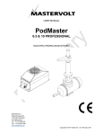
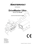
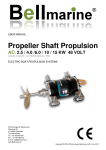
USER MANUAL PodMaster Steerable 2.0, 2.5 ELECTRIC PROPULSION SYSTEM MASTERVOLT Snijdersbergweg 93, 1105 AN Amsterdam The Netherlands Tel.: +31-20-3422100 Fax.: +31-20-6971006 www.mastervolt.com Copyright © 2011 Mastervolt, v 0.1 February 2011 CONTENTS CONTENTS 1 GENERAL INFORMATION .................................................................................................................................................. 4 1.1 USE OF THIS MANUAL ........................................................................................................................................ 4 1.2 VALIDITY OF THIS MANUAL ............................................................................................................................... 4 1.3 GUARANTEE SPECIFICATION ........................................................................................................................... 4 1.4 LIABILITY .............................................................................................................................................................. 4 2 SAFETY GUIDELINES AND MEASURES .......................................................................................................................... 5 2.1 WARNINGS AND SYMBOLS................................................................................................................................ 5 2.2 USE FOR INTENDED PURPOSE ........................................................................................................................ 5 2.3 GENERAL SAFETY AND INSTALLATION PRECAUTIONS ............................................................................... 5 2.4 WARNING REGARDING LIFE SUPPORT APPLICATIONS ............................................................................... 5 2.5 WARNING REGARDING THE USE OF BATTERIES .......................................................................................... 6 3 HOW IT WORKS .................................................................................................................................................................. 7 3.1 PODMASTER STEERABLE SYSTEM ................................................................................................................. 7 3.2 COMPONENTS ..................................................................................................................................................... 7 3.3 MOTOR CONTROLLER AND DC MOTOR .......................................................................................................... 8 3.4 DISPLAY, JOYSTICK AND MOTOR SWITCH ..................................................................................................... 8 3.5 MAIN SWITCH AND FUSE ................................................................................................................................... 8 3.6 CONNECTION CABLES ....................................................................................................................................... 8 4 OPERATION ......................................................................................................................................................................... 9 4.1 SWITCHING ON AND OFF ................................................................................................................................... 9 4.2 USE OF THE DISPLAY ......................................................................................................................................... 9 4.3 USE OF THE JOYSTICK ...................................................................................................................................... 9 4.4 DEPARTURE......................................................................................................................................................... 9 4.5 ARRIVAL ............................................................................................................................................................... 9 5 INSTALLATION .................................................................................................................................................................. 10 5.1 COMPONENTS ................................................................................................................................................... 10 5.2 MOTOR................................................................................................................................................................ 10 5.2.1 ANODE PROTECTION ...................................................................................................................... 11 5.3 MOTOR CONTROLLER...................................................................................................................................... 11 5.4 DISPLAY .............................................................................................................................................................. 11 5.5 JOYSTICK ........................................................................................................................................................... 12 5.6 WIRING................................................................................................................................................................ 12 5.6.1 CONNECTION OF THE POWER CABLES....................................................................................... 14 5.6.2 CONNECTION OF DISPLAY AND JOYSTICK ................................................................................. 14 5.6.3 CONNECTION OF BATTERY CABLES ............................................................................................ 14 5.7 COMMISSIONING ............................................................................................................................................... 15 5.8 CALIBRATION ..................................................................................................................................................... 15 6 MAINTENANCE.................................................................................................................................................................. 16 6.1 PREVENTIVE MAINTENANCE .......................................................................................................................... 16 6.2 MAINTENANCE................................................................................................................................................... 16 6.3 ANODE PROTECTION ....................................................................................................................................... 16 7 TROUBLE SHOOTING ...................................................................................................................................................... 17 8 TECHNICAL DATA ............................................................................................................................................................ 18 8.1 TECHNICAL SPECIFICATIONS ......................................................................................................................... 18 8.2 DIMENSIONS ...................................................................................................................................................... 19 8.2.1 MOTOR CONTROLLER .................................................................................................................... 19 2 February 2011 / PodMaster Steerable 2.0 2.5 /EN CONTENTS 8.2.2 9 MOTOR .............................................................................................................................................. 20 ORDERING INFORMATION .............................................................................................................................................. 21 EN / PodMaster Steerable / February 2011 3 GENERAL INFORMATION 1 GENERAL INFORMATION 1.1 USE OF THIS MANUAL Copyright © 2011 Mastervolt. All rights reserved. Reproduction, transfer, distribution or storage of part or all of the contents in this document in any form without the prior written permission of Mastervolt is prohibited. 1.4 LIABILITY Mastervolt can accept no liability for: Consequential damage due to use of the PodMaster Steerable; Possible errors in the manuals and their consequences. This manual contains important safety and operating instructions for the safe and effective operation, maintenance and possible correction of minor malfunctions of the PodMaster Steerable. It is therefore obligatory that every person who works on or with the PodMaster Steerable is completely familiar with the contents of this manual, and that he/she carefully follows the instructions and important safety instructions contained herein. Installation and maintenance of the PodMaster Steerable systems may only be performed by qualified and authorized personnel, in accordance with regulations and in compliance with the mentioned safety measures. Keep this manual in a safe place! 1.2 VALIDITY OF THIS MANUAL All of the specifications, provisions and instructions contained in this manual apply solely to standard versions of the PodMaster Steerable delivered by Mastervolt. For other models see other manuals available on our website: www.mastervolt.com 1.3 GUARANTEE SPECIFICATION Mastervolt guarantees that this unit has been built according to the legally applicable standards and specifications. Should work take place, which is not in accordance with the guidelines, instructions and specifications contained in this user manual, then damage may occur and/or the unit may no longer meet its specifications. All of these matters may mean that the guarantee becomes void. The guarantee is limited to the costs of repair and/or replacement of the product. Costs for installation labor or shipping of the defective parts are not covered by this guarantee. During production and before delivery, all equipment is tested and inspected. The standard warranty period is two years after purchase. 4 February 2011 / PodMaster Steerable 2.0 2.5 /EN SAFETY GUIDELINES AND MEASURES 2 SAFETY GUIDELINES AND MEASURES 2.1 WARNINGS AND SYMBOLS The following warning, caution and attention symbols are used in this manual. WARNING! A WARNING refers to possible injury to persons if the user does not (carefully) follow the procedures. CAUTION! A CAUTION sign refers to possible significant damage to the equipment if the user does not (carefully) follow the procedures, restrictions and rules. 2.4 WARNING REGARDING LIFE SUPPORT APPLICATIONS The PodMaster Steerable is not intended for use in any medical equipment that is intended for use as a component of any life support system, unless a specific written agreement pertaining to such intended use is executed between the manufacturer and Mastervolt. Such agreement will require the equipment manufacturer either to contract additional reliability testing of the PodMaster Steerable and/or to commit to undertake such testing as a part of the manufacturing process. In addition, the manufacturer must agree to indemnify and not hold Mastervolt responsible for any claims arising from the use of the PodMaster Steerable in life support equipment. ATTENTION! An ATTENTION sign refers to procedures, circumstances, etc. which deserve extra attention. 2.2 USE FOR INTENDED PURPOSE The PodMaster Steerable may only be used for ship propulsion and according to the installation, operation and maintenance instructions of this manual. 2.3 GENERAL SAFETY AND INSTALLATION PRECAUTIONS Read this manual thoroughly before installing and/or using the electric components; Follow the assembly instructions carefully; Only work with the controller when the drive is switched off. It is important to switch off the power supply of the electric drive with the main switch. Remove the key and keep it with you so that nobody else can turn it back on; Be aware of your speed. The speed is often underestimated because of the lack of sound; Be alert to your surroundings; silent sail means that others can hardly hear you; The motor has non-shielded rotating parts. Be sure that loose clothing can not get caught in the shaft or coupling. Avoid contact with rotating parts; Make sure that when building the motor, the wiring is properly insulated. A short circuit can cause fire. EN / PodMaster Steerable / February 2011 5 SAFETY GUIDELINES AND MEASURES 2.5 WARNING REGARDING THE USE OF BATTERIES The battery pack that is suitable for the PodMaster Steerable 2.0 is a 24 Volt battery pack, for the PodMaster Steerable 2.5 a 36 Volt battery pack. The battery capacity can be chosen by the customer. Play attention to the following when working with batteries. Someone should be within hearing distance or close enough to come to your aid when you work near a lead-acid or Li-Ion battery; Have plenty of fresh water and soap nearby in case battery acid contacts skin, clothing or eyes; Wear complete eye protection and clothing protection. Avoid touching eyes while working near a battery; If battery acid contacts skin or clothing, wash immediately with soap and water. If acid enters the eye, immediately flood the eye with cold running water for at least 10 minutes and get medical attention immediately; NEVER smoke or allow a spark or flame in the vicinity of a battery or engine; Do not short circuit batteries, as this may result in an explosion and fire hazard! Take extra care to reduce the risk of dropping a metal tool onto a battery. It might spark or short-circuit the battery or other electrical part and it may cause an explosion; Remove personal metal items such as rings, bracelets, necklaces and watches when working with a battery. A battery can produce a short-circuit current that is high enough to weld a ring or anything like it, to metal, causing a severe burn; NEVER charge a frozen battery; Excessive battery discharge and/or high charging voltages can cause serious damage to batteries. Do not exceed the recommended limits of the discharge level of your batteries; If it is necessary to remove a battery, always remove the grounded terminal from the battery first. Make sure all accessories are off, so as not to cause an arc; Be sure that the area around the battery is well ventilated while the battery is being charged. Refer to the recommendations of the battery manufacturer; Batteries are heavy! It may become a projectile if it is involved in an accident! Ensure adequate and secure mounting and always use suitable handling equipment for transportation. 6 February 2011 / PodMaster Steerable 2.0 2.5 /EN HOW IT WORKS 3 HOW IT WORKS INCLUDED IN THE PODMASTER SYSTEM JOYSTICK DISPLAY BATTERY CONTROLLER FUSE MOTOR PROPELLER MAIN SWITCH Figure 1: System block diagram 3.1 PODMASTER STEERABLE SYSTEM The diagram of Figure 1 gives a simplified view of the PodMaster Steerable system. The main parts of the system are the battery and controller, supplying the motor with energy, and the motor with propeller providing the thrust for the propulsion and the ability to steer. The system is operated by the joystick that gives speed and direction information to the controller so it can give the right amount of power to the motor. Information about battery voltage, remaining power, thrust power and more is shown on the display. Furthermore, there is a fuse for protection and a main switch for powering on and off. The motor controller is the key element in the system. It manages operation, protection and information. EN / PodMaster Steerable / February 2011 3.2 COMPONENTS The PodMaster Steerable comes with the following components: Motor controller Submerged (podded) DC motor with bronze 3-blade propeller Display with integrated motor switch Main switch Fuse and fuse box Signal cable Adapter cable for joystick 4 connectors for power cables Please check the contents of the box before you start with the installation. If any of the items is missing, please contact your supplier. 7 HOW IT WORKS 3.3 MOTOR CONTROLLER AND DC MOTOR The motor controller is specifically designed for controlling the speed of the PodMaster Steerable permanent magnet DC motor. This controller-motor combination is specifically designed for electric propulsion in boats. The controller is equipped with a number of specific features that are important for electric propulsion in boats; e.g. the cooling is temperature controlled. 3.4 The display gives information on battery status, motor power and has an integrated motor switch for switching the system on and off. The display is connected to the motor controller. The joystick (to be ordered separately) is used to control the speed in forward and backward direction when sailing. The joystick is connected to the display. 3.5 The motor is placed below the hull, submerged in the water. It uses powerful permanent magnets which results in high efficiency and a high power output to volume / weight ratio. DISPLAY, JOYSTICK AND MOTOR SWITCH MAIN SWITCH AND FUSE The main switch is mounted between the fuse box and the motor controller in order to disconnect the batteries during emergencies and maintenance. 3.6 CONNECTION CABLES Figure 1 shows a simplified view of the cabling connections and the components of the PodMaster Steerable. All connections are made with connectors to prevent mistakes during installation. 8 February 2011 / PodMaster Steerable 2.0 2.5 /EN OPERATION 4 OPERATION 4.1 SWITCHING ON AND OFF 4.3 The system is switched on by turning the motor switch key on the display in clockwise direction. The motor switch has two positions: "off" and "on". The system is switched off by turning the motor switch key counter-clockwise to the “off” position. off USE OF THE JOYSTICK The desired power and speed can be adjusted in forward and backward direction with the joystick, by turning it over the full stroke. This happens without intermediate steps. Figure 4 shows the joystick with default forward (clockwise) and backward (counter clockwise) operation. This default setting can be changed in calibration, see section 5.8. on Figure 2: Motor switch positions 4.2 USE OF THE DISPLAY After switching on the system, the display lights up. The display has two lines, with 16 characters each. Communication with the controller takes place by serial data transfer. The display power is supplied by the motor controller. Figure 4: Joystick There are several types of joysticks available, which is why the joystick is not a standard part of the system. In this manual a standard joystick is used as an example. Refer to the ordering information in chapter 9 for alternative types. 4.4 DEPARTURE Before departure, always check the system for correct functioning. 1 2 3 4 5 2 4 - 0 V 9 9 9 9 h 0 - 1 K B A T 9 9 % 6 Follow these steps: 1. Disconnect the shore connection. 2. Turn the main switch on. 3. Put the joystick in the neutral position. 4. Turn the system on with the motor switch on the display. 5. Check the battery condition. 7 4.5 Figure 3: Display The display module contains: 1. Display 2. Motor switch The display gives the following information: 3. Battery voltage in Volts 4. Remaining time in hours and minutes 5. Motor power in kW 6. Residual capacity of the battery in % 7. Error code ARRIVAL Follow these steps after arrival: 1. Put the joystick in the neutral position. 2. Check the battery condition. 3. Turn the motor switch off. 4. Connect the shore connection and make sure it works properly. 5. Reload the batteries after arrival. See chapter 7 for a description of the error codes. EN / PodMaster Steerable / February 2011 9 INSTALLATION 5 INSTALLATION During installation and commissioning of the PodMaster Steerable, the safety instructions of chapter 2 must be followed. 5.1 COMPONENTS See the block diagram in chapter 3 and the wiring diagram in section 5.6. 5.2 ATTENTION! The top of the rudder trunk needs to be above water level, even taking into account the angle the boat makes when accelerating or sailing. In case the standard length of the rudder trunk does not ensure this, measures need to be taken to extend the length of the trunk in a waterproof way. MOTOR A PodMaster Steerable electric drive system is quiet and has little vibration when installed correctly. In order to achieve this, pay close attention to the placement of the motor. 7 8 1 2 6 Below are some support guidelines for installation: 1. Drill a hole in the boat hull with the diameter of the rudder trunk at the desired location. 2. Remove the lever arm, supporting rings and mounting nut from the rudder trunk (see Figure 5, item 2, 6 and 7). 3. From under the boat, pull the rudder trunk through the hole in the hull. 4. Fix the rudder trunk to the hull by using the mounting nut (see Figure 5, item 2). 5. Fix the rudder trunk using a reinforced housing in the hull (similar to when placing a conventional rudder). This housing needs to ensure that forces/torques on the rudder trunk are well absorbed by the hull. An example of a construction that could be used is given in Figure 6 and Figure 7. 3 4 5 Figure 5: The PodMaster Steerable motor 1. 2. 3. 4. 5. 6. 7. 8. Rudder trunk Mounting nut Motor 3-blade bronze propeller Propeller anode Stainless steel anti-cavitation plate Lever arm Supporting ring Figure 6: Reinforced housing – Overview with part of the boat hull ATTENTION! The motor must be installed by qualified personnel, familiar with general boat building techniques required for steering systems. 10 February 2011 / PodMaster Steerable 2.0 2.5 /EN INSTALLATION ATTENTION! To protect the seawater resistant aluminum (AlMg-5) motor housing, a second (set of) sacrificial anode(s) needs to be placed on the boat near the motor housing and needs to be electrically connected to that motor housing. This anode is not provided with the system as the proper choice of anode depends on environment (water) conditions and other material use on the boat. In general, we recommend: - in fresh water: magnesium anodes - in brackish water: aluminum anodes (Mil-A24779 SH) - in salt water: zinc anodes (Mil-A-18001K). Nevertheless it is always recommended to directly consult an expert (Mastervolt or your local expert on anode protection) on the specific situation at hand. CAUTION! Beware that properly placing a sacrificial anode on your boat to protect the aluminum motor housing is essential and failure to do so might cause severe damage to your system. Damage to the motor caused by galvanic corrosion is not covered by our product warranty. Figure 7: Reinforced housing – top view with part of the boat hull See chapter 8.2 for the motor dimensions. 5.2.1 ANODE PROTECTION When two different metals are physically or electrically connected underwater, a current will flow between these two metals. The electrons that make up that current are supplied by one of the metals giving up bits of itself, in the form of metal ions. This is called galvanic corrosion and it destroys underwater metals. The most common galvanic corrosion is present in case of a bronze or aluminum propeller on a stainless steel shaft, but other metal (motor) housings are also at risk. The best way to prevent galvanic corrosion is to add a third metal into the circuit, one that is potentially more reactive than the other two metals. This piece of metal is called a sacrificial anode. With the PodMaster Steerable system, one sacrificial anode is included to protect the propeller. This is an aluminum anode and is to be placed on the shaft. 5.3 MOTOR CONTROLLER When mounting the controller, there must be at least 50 mm space above and under it. There must also be sufficient space for the cable connections. Note the following when installing the motor controller: Make sure that there is adequate ventilation and do not cover up the suction and blast hole; The motor controller must be mounted at a dry, wellprotected and accessible location in the boat; Never install a controller near a so-called wet or open battery; Air-intake of the controller must be sufficient; Ensure that the intake opening can not be blocked; The controller must be mounted on a flat surface. See section 8.2 for the controller dimensions. 5.4 DISPLAY The display is usually mounted on the control console of the boat. The location of the display is not critical, it is important that (rain) water does not remain on the display and can run off. Upright or slightly slanted installation is recommended. This does not apply to an indoor arrangement. The display requires a rectangular 155 mm by 55 mm (width by height) panel cut-out. Note that the wiring of the display needs to be finished before it is fully mounted with the screws. EN / PodMaster Steerable / February 2011 11 INSTALLATION 5.5 JOYSTICK The joystick is mounted vertically, for instance, on the control console. Note: The joystick is splash proof only. Therefore, the joystick should not continuously be in contact with water. Position the joystick carefully; The handle has to be able to rotate freely in both directions; Choose the location so that the risk of turning the handle in the unwanted direction is minimal. 5.6 WIRING Every PodMaster Steerable system comes with the following wiring components: 4 connectors for power (battery and motor) cables; Signal cable. 12 The power cables for connecting the batteries and the power cables from the motor controller to the motor are not included. The cables from the motor and batteries to the controller should be flexible 25 mm2 cables. It is recommended to tie the cables together with a cable tie when all 4 flexible cables are plugged in. The wiring of the cables is explained in the following sections. Connect the cables in the following order: 1. Connect the motor cables and temperature sensor. 2. Connect the display and joystick. 3. Connect the battery cables. See the wiring diagram in Figure 8. February 2011 / PodMaster Steerable 2.0 2.5 /EN INSTALLATION Display Joystick Motor controller Main switch Fuse _ Battery + Motor Figure 8: Wiring diagram The battery, power cables and joystick are not included in the system. For ordering information, see chapter 9. EN / PodMaster Steerable / February 2011 13 INSTALLATION 5.6.1 CONNECTION OF THE POWER CABLES WARNING! Make sure that when connecting the battery and the motor controller, the fuse is removed and the main switch is switched off. 5.6.2 CONNECTION OF DISPLAY AND JOYSTICK The control signals to the display pass through the signal cable that is connected to the controller with the 12-pin plug. The 12-pin plug is to be plugged into the motor controller. 1 Note the following when connecting the cables: The positive terminal is clearly marked with a red mark on the motor controller; The main switch must be mounted at an accessible location between the fuse and the motor controller, so that the system can be disconnected from the batteries in case of an emergency or in case of maintenance; The fuse must be placed as close as possible to the batteries to ensure maximum protection; The + cable runs from the battery to the fuse and the – cable runs from the battery to the – pole of the controller. Specifications for connecting the power cables: 2 Motor controller > 25 mm Fuse T 125 Ampere Power 2.5 kW Voltage 24 Volts Figure 9: Quick connect couplings for power cable Two quick-connect couplings are included for connection to the motor controller (see Figure 9). Follow these steps to connect the quick connect couplings: 1. Install the couplings with care at the ends of the cables. 2. Turn the couplings one stroke counter-clockwise. The cable is now secured and cannot get loose as a result of vibration. 3. Place the coupling on the controller. Refer to the manual of the battery supplier for more information about the connection and location of the battery. Follow these steps after installation and before switching on the power: 1. Check all connections again. 2. Check the voltage of the battery. 3. When you are convinced that everything has been connected properly, turn the main switch on. 14 2 Figure 10: Back side of the display The signal cable has a 7-pin plug for the display. Next to the signal cable, the short joystick adapter cable needs to be connected to the display in order to connect the (separately ordered) joystick. Follow these steps: 1. Take the rubber cover off the back of the display. 2. Slide the two black cable sleeves that are in the rubber cover over the signal cable and the joystick adapter cable. 3. Slide the cables through the rubber cover and fix the cable sleeves in the rubber cover. 4. Insert the 7-pin plug at the back of the display in the upper connector (see Figure 10, item 1). 5. Insert the plug of the joystick adapter cable in the lower connector (see Figure 10, item 2). 6. Slide the full rubber cover including cable sleeves over the cables until it reaches the display and can be mounted as one part in the panel cut-out. 5.6.3 CONNECTION OF BATTERY CABLES WARNING! Make sure that when connecting the battery and the motor controller, the fuse is removed and the main switch is switched off. Note the following when connecting the cables: The positive terminal is clearly marked with a red mark on the motor controller; The main switch must be mounted at an accessible location between the fuse and the motor controller, so that the system can be disconnected from the batteries in case of an emergency or in case of maintenance; The fuse must be placed as close as possible to the batteries to ensure maximum protection; February 2011 / PodMaster Steerable 2.0 2.5 /EN INSTALLATION The + cable runs from the battery to the fuse and the – cable runs from the battery to the – pole of the controller. Specifications for connecting the power cables: 2 Motor controller > 25 mm Power 2.5 kW Voltage 24 Volts 5.8 CALIBRATION The PodMaster Steerable can be calibrated by the owner or a specialist. It involves the following steps: Setting the battery capacity; Calibrating the joystick; Resetting the battery to 99%. CAUTION! These actions may only be performed when the batteries are fully charged. The battery reference voltage is stored in memory. If the battery is charged less than 80%, the system calculates the remaining capacity itself. There will be no new reference voltage stored. Figure 11: Quick connect couplings for the motor controller Two quick-connect couplings are included for connection to the motor controller (see Figure 9). Follow these steps to connect the quick connect couplings: 1. Install the couplings with care at the ends of the cables. 2. Turn the couplings one stroke counter-clockwise. The cable is now under tension and cannot therefore get loose as a result of vibration. 3. Place the coupling on the controller. Refer to the manual of the battery supplier for more information about the connection and location of the battery. Follow these steps after installation and before switching on the power: 1. Check all connections again. 2. Check the voltage of the battery. 3. If you are convinced that everything has been properly connected, turn the main switch on. 5.7 COMMISSIONING The display shows the residual battery capacity and the remaining sailing time, with the current speed. To calculate these data, the system must know the battery capacity. This value must be entered into the system. After all connections have been made, the battery capacity can be set and the system must be reset. To reset the system, follow these steps: 1. Make sure that all batteries are fully charged. The LED lights on the charger(s) give 100%. 2. Remove the shore connection. 3. Wait for two minutes. 4. Perform calibration (see next section). EN / PodMaster Steerable / February 2011 ATTENTION! Read the following 10 steps first before carrying them out. The following first 4 steps must be carried out immediately one after the other. Do not pause between the steps. 1. Turn on the motor switch. 2. Turn the joystick counter-clockwise to the farthest position. 3. Turn the joystick clockwise to the farthest position. 4. Turn the joystick to the neutral position in the middle. The screen then shows: “Full forward”. 5. Turn the joystick full forward (counter-clockwise). After five seconds the screen shows: “Full backward”. 6. Turn the joystick full backward (clockwise). After five seconds the screen shows: “Neutral”. 7. Turn the joystick to the neutral position in the middle. After five seconds, the message “Saved” is shown on the screen. The joystick is now calibrated with the new reference voltage. If you want to adjust the battery capacity value (in Ah), follow these steps: 8. Move the joystick within three seconds of performing step 7 and the Ah value will change. 9. Use the joystick to change the Ah value. 10. Move the joystick to the neutral position when the correct value is reached. After three seconds, this value is programmed into the memory. 15 MAINTENANCE 6 MAINTENANCE 6.1 PREVENTIVE MAINTENANCE Check your whole system regularly on the following points: Check the bilge and motor compartment for unwanted moisture or water; Check the operation of the automatic bilge pump; Check the system for irregularities, such as abnormal noise, vibration and wear. Keep the system always connected (even in winter storage) to the shore connection. This will keep the batteries in 100% condition and prevents self-discharging of batteries. If the system is not going to be used for a long time and a permanent shore connection is not available, then charge the batteries for 100% and remove the fuse. 6.2 This maintenance can only be done by Mastervolt, please contact your Mastervolt service contact. 6.3 ANODE PROTECTION The motor housing and propeller shaft are protected with sacrificial anodes. Check the anodes for corrosion on a regular base; at least once every year. Replace the sacrificial anodes when half of the anode has been lost to corrosion. CAUTION! Never coat anodes with paint or anything else, for it will lose its function. MAINTENANCE After approximately 2,000 hours of use, the carbon brushes inside the podded motor need to be replaced. 16 February 2011 / PodMaster Steerable 2.0 2.5 /EN TROUBLE SHOOTING 7 TROUBLE SHOOTING In case of a failure, the PodMaster Steerable display shows an error code to help you find the cause. If you cannot solve a problem with the aid of the fault finding table below, contact your local Mastervolt Service Centre. See www.mastervolt.com. Make sure you keep the article and serial number close at hand. The following table shows the most common errors. Message Batt. Low Batt. High Error The battery voltage is too low The battery voltage is too high JOYWIRE+ The positive wire of the joystick is interrupted JOYWIRE- The negative or middle wire of the joystick is interrupted The joystick is not in the neutral position when activating the system The controller is too hot JOYSTICK Contr. Hot NTC Wire OVERLOAD The temperature sensor of the controller is interrupted The controller is overloaded, as a result of, for example, dirt in the propeller EN / PodMaster Steerable / February 2011 Solution Charge the batteries Check whether the nominal battery pack voltage is equal to the PodMaster Steerable system's required voltage Check the wire and connections. Change the wire if necessary Check the wires and connections. Change the wire if necessary Put the joystick in the neutral position Let the motor controller cool down and check the controller housing Contact Mastervolt Service Center Check the propeller and clean if necessary 17 TECHNICAL DATA 8 TECHNICAL DATA 8.1 TECHNICAL SPECIFICATIONS Model Article number Battery voltage Nominal battery voltage Battery voltage Performance Output voltage Nominal motor current Maximum motor current Motor type Maximum motor power Control method Motor speed Related torque Read parameters Standby mode Safety Undervoltage Overvoltage Current Thermal safety Thermal motor Environment Temperature Protection class Weight Motor weight Motor controller weight Total system weight 18 PodMaster Steerable 2.0 140700200 PodMaster Steerable 2.5 140700250 24 Volt 19 - 33 Volt 36 Volt 28 – 45 Volt Adjustable to 98% of battery voltage 110 A 150 A for 60 s Brushed 2.0 kW 2.5 kW PWM 1800 rpm 11 Nm 13 Nm Via display Automatic after 15 minutes 19 Volt 33 Volt 28 Volt 45 Volt 110 A, 150 A for 60 s Reduction of power in steps to 0 when overheated Reduction of power in steps to 0 when overheated -25 - 40°C IP 21 22 kg 25 kg 4.5 kg 27 kg 30 kg February 2011 / PodMaster Steerable 2.0 2.5 /EN 8.2 DIMENSIONS 8.2.1 MOTOR CONTROLLER Front Side 148 162 150 202 259 Top 182 Figure 12: Dimensions of the motor controller in mm Front Side 5.82 6.39 5.90 202 10.20 Top 7.14 Figure 13: Dimensions of the motor controller in inches 8.2.2 MOTOR Back Side 30 150 502 42 162 125 229 530 387 205 Top Figure 14: Dimensions of the motor in mm Back Side 1.65 4.92 5.89 19.78 1.18 6.38 9.00 20.87 15.25 8.07 Top Figure 15: Dimensions of the DC motor in inches 9 ORDERING INFORMATION Part number 141500010 141500030 141500120 141500220 142000355 Description ControlMaster Casual – single version, side mount ControlMaster Sport – single version, side mount ControlMaster Sport T – single version, top mount ControlMaster Sport TD – double version, top mount Extension cable set 6 metres