1
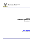
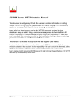
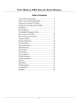
Version #090915
INSTALLATION & OPERATING
USER MANUAL
Four cylinder
Leveling Systems:
Vehicle
Applications:
Automatic Leveling
Platinum Leveling RVs /Motorhomes
Wireless Leveling Specialty Vehicles
Manual Leveling
Two cylinder
systems:
Stabilizing Systems
QUADRA MANUFACTURING
BIGFOOT LEVELING SYSTEMS
305 US 131 SOUTH
WHITE PIGEON, MI 49099
800-752-9815 (PHONE)
269-483-9636 (FAX)
BIGFOOTLEVELER
BIGFOOTLEVELER.com
LEVELER.com
Identifying your leveling system…
Automatic System
Previous
Version
Automatically levels the vehicle
with supreme precision.
Manual operation feature.
All-up & Ignition safety feature.
Emergency Retract operation.
Lifetime warranty on cylinders.
Central & Quad Pump Formats.
Platinum System
Automatically deploys all four jacks
to level the vehicle from front to rear.
Manual operation feature.
All-up & Ignition safety feature.
Simple, no nonsense design.
Central Pump System.
Wireless System
Freedom to roam while operating.
Operates two jacks simultaneously
to prevent frame twist/damage.
All-up safety feature.
Central Pump System.
Manual System
Operates jacks individually or all at once.
All-up safety feature.
Emergency Retract operation.
Quad Pump System.
2pt Stabilizing Systems
1
Operation page 2
Cylinders pages 5-12
Tank Assembly pages 13-14
Wiring pages 15-17
Bleeding page 18
Troubleshooting page 19
Warranty page 23
Operation page 3
Cylinders pages 5-12
Tank Assembly page 13
Wiring pages 15-17
Bleeding page 18
Troubleshooting page 19
Warranty page 23
Operation page 4
Cylinders pages 5-12
Tank Assembly page 13
Wiring pages 15-17
Bleeding page 18
Troubleshooting page 19
Warranty page 23
Operation page 3
Cylinders page 5-12
Tank Assembly page 14
Wiring pages 15-17
Bleeding page 18
Troubleshooting page 19
Warranty page 23
Cylinders pages 5-12, 16
Controls/Wiring page 20-22
Power/Plumbing page 17,22
Warranty page 23
Automatic Leveling System Controls
Control Panel Operation…
- Make sure the key is out
of the vehicle ignition.
- Previous version
of panel to the right.
1. Turn panel/system on and let system run through its diagnostic mode. Lights will flash
clockwise around the green foot. (System will not operate with the ignition key ON)
2. When the lights stop flashing, it’s time to choose your function (MANUAL or AUTOMATIC). If
choosing MANUAL, press and hold button until light comes on. For AUTOMATIC, simply press
once and release.
3. When in the MANUAL mode, each leveler may be operated individually. FRONT operates right
front. RIGHT operates right rear. REAR operates left rear. LEFT operates left front. When using
this feature it is important to level the coach by using two levelers at a time or together. For
example, right front and right rear, this puts less stress on the frame. To retract, press and
hold the RETRACT button & the jack button.
4. When using the AUTOMATIC feature, simply press the AUTO button and then let the system
operate itself. It is important at this time that there is NO MOVEMENT IN THE COACH. This
process will take 1-3 minutes. To retract the levelers simply turn panel on and press RETRACT.
Programming the Automatic Leveling System
Turn panel/system on and let system run through its diagnostic mode. Lights will flash
clockwise around the green foot.
When the lights stop flashing, push the button labeled “FRONT” 5 times. Then press the
button labeled “REAR” 5 times. Once you have done this all lights on panel will begin to flash.
This means you have reached in the system what is called zero mode. At this time you can
operate each corner or pair of levelers individually.
FRONT indicator operates the right front.
RIGHT operates the right rear.
REAR operates the left rear.
LEFT operates the left front.
Keep in mind the twisting/flexing of the vehicle’s frame. Try to operate jacks in pairs when possible.
Once you have the coach level, you can now store a new program into the system. To do so, press
the RETRACT button 3 times. If you do not want to store a new program, simply retract jacks in manual
mode to avoid changing the original program (press and hold RETACT & jack button)
2
Platinum Leveling System Controls
Control Panel Operation…
Panel also available in black, NOTE: 1. Panel turns on when ignition turns on to inform user if jacks are up or
down (alarm sounds). 2. Due to another safety feature, to operate the “START” and “RETRACT ALL” buttons,
press and hold the button for 1-2 seconds then release.
Adjustment Buttons
Extend System:
All Up Light
1.
Press the Power Button (Red LED will come on constant).
2.
Press the Start Button, this brings the front of the vehicle nearly level to the
rear and stabilizes the rear as well. (LED will come on until program is finished, pressing
any button during operation will cancel program, Vehicle Ignition must be OFF).
3.
Done! Vehicle is now stabilized, if additional adjustments are desired:
1. Press Extend (now in “Extend Mode” LED will come on).
2. Press & Hold the Adjustment Button for the designated corner(s) of the vehicle that
is low or high. (Ex. Right or Curb side is low, press & hold RIGHT FRONT & RIGHT REAR until level,
driver’s side is considered the left side for reference).
4.
Power Off (will automatically shut off after 10 minutes of no activity).
Retract System:
1. Press the Power Button (Red LED will come on).
2. Press the Retract All Button until the green “All Up” light comes on constant.
(This process will take up to 60 seconds. After 60 seconds the green light will flash, this means that one
or more of the jacks did not fully retract, see troubleshooting)
Always do a visual check to verify that all the jacks are fully retracted prior to operating the vehicle.
Manual Leveling System Controls
Turn panel on, press Extend or Retract, then press & hold the designated jack or press & hold the All button to
operate all four jacks simultaneously. This panel has the All up feature as well and an air dump feature if
equipped. Press and hold Emergency Retract to retract jacks in-case of limit switch failure.
3
Wireless Leveling System Controls
STEP 1:
Press the “WAKE” button on the remote to turn receiver on.
STEP 2:
To lift the Front of the coach, press “FRONT” then “EXTEND.” Hold this
down until the coach moves, then release.
STEP 3:
To lift the Rear of the coach, press “REAR” then “EXTEND.” Again hold this
down until the coach moves, then release.
STEP 4:
To lift the Driver side of the coach, press “DRIVER” then “EXTEND.” Hold
until desired height is reached, then release.
STEP 5:
To lift the Passenger side of the coach,
press “PASSENGER” then “EXTEND.” Again,
hold until desired height is reached, release.
STEP 6:
Press “WAKE” to put the system to sleep.
STEP 1:
When you are ready to leave press “WAKE”
to turn on the receiver.
STEP 2:
To lower the Rear of the coach, press “REAR”
then “RETRACT.” Hold this down until the rear
jacks are completely retracted.
STEP 3:
To lower the Front of the coach, press “FRONT” then “RETRACT.” Again
hold this down until the front jacks are completely retracted.
Press “WAKE” to put the system to sleep.
STEP 4:
The indicator light & alarm will alert you when one of the jacks are down
before you drive away. This is a standard feature on the wireless system.
Installing the Wireless Receiver
Plug the receiver pigtail into the plug attached to the central pump tank assembly.
Mount the receiver using the provided TEK screws in an easy to access area without placing it in harm’s way.
For example, although the receiver is weatherproof, face the front component side of the receiver towards the
rear of the vehicle where road debris reduce the risk of damaging the receiver.
If you are having trouble with your wireless setup (intermittent performance) the
wireless connection may have some interference based on the location of the receiver
(Ex. thick steel boxes) you may need to relocate your wireless receiver to another area,
such as inside the coach. In order to do this you will have to order a part from
Quadra Manufacturing (800-752-9815) “EZ Extension Harness - Part#: M41600”
4
Cylinder Installation & Assembly
Mounting the Cylinders
Pre-assemble jack prior to hanging on previously mounted weld-on bracket.
- Attach foot pad with ¾” thin jam nut using a 1 1/16” socket.
- Remove port plugs with 3/16” allen wrench.
- Install supplied JIC elbow fittings to the bottom & top ports with 9/16” wrench.
- DO NOT install the extend hose to the top port on central pump systems yet, this will be done later
on in installation (due to the length of hose they must go through a bleeding process).
- Place ¼” clevis pin in limit switch barrel then insert threaded limit switch with 7/8” wrench.
- For jack locations see diagrams on the following pages, but typically the front jacks should be under
the cab and the rear jacks should be within 60” behind the rear axle.
- If it is a weld-on application, make sure the weld-on bracket is level and you get good penetration to
the frame with full welds the entire length of the bracket. Sometimes it is easier to mount jack prior
to welding by lifting assembly with floor jack, be sure to verify levelness and ground clearance.
- Hang jack using at minimum of four 7/16” x 1.75” grade 8 bolts, hex nuts & lock washers. If you have
17k-lb or larger jacks (3 3/8” diameter or larger) you need a minimum of six bolts per jack. Prior to
tightening, verify jack is straight & level using carpenter’s level. Tighten with 5/8” wrench on bolt,
11/16” socket on nut, tighten to 70 ft.-lbs. (See Fig. 1)
Fig. 1
The jack pictured in this diagram may not match
the jack for your vehicle specific or universal kit.
Identifying jacks by diameter:
2 3/8” = 8k-lb jack
2 7/8” = 12k-lb jack
3 3/8” = 17k-lb jack
3 7/8” = 24k-lb jack
If mounting the rear jacks
between the vehicle’s frame rails
also called an “inside mount”
a crossbrace is required in the
installation for structural stability.
5
Vehicle: MERCEDES BENZ SPRINTER 3500 CHASSIS CAB
System: Front Jack Mounting Location -Universal to all 4pt systems
Front Cylinder Mounting Location Here
Drilling of frame required.
Can mount behind cab if desired.
Components Required:
(2) #M0211 or #M0211-1 8k11 Cylinders
(2) #M28020 Sprinter Channel Bracket
(2) #M28025 Sprinter Hat Bracket
(4) #M80722 3/4-10 G8 Hex Bolt 5” long
(4) #M80735 3/4-10 G8 Hex Nut
(4) #M80734 3/4” G8 Lock Washer
(4) #M80316 7/16-14 G8 Hex Bolt 1.75” long
(4) #M80344 7/16-14 G8 Hex Nut
(4) #M80346 7/16” G8 Lock Washer
Driver’s side jack location (under cab) cylinder to be mounted on the outside face of the frame, see bracket assembly diagrams at the
bottom of the page. Place the “Sprinter Channel Bracket” on the frame and mark the holes for drilling.
Passenger side jack location (under cab) cylinder also mounted on the
outside face of the frame. Removal of the storage box in the step rail (shown
in picture) must be removed. Angle drill will be required for 5/8” or 3/4”
hardware.
6
Vehicle: MERCEDES BENZ SPRINTER 3500 CHASSIS CAB
System: Rear Jack Mounting Location for Automatic Leveling System
Rear Cylinder Mounting Location Here
Check for access to first pair of ½” hardware
on the outside face of the driver’s side frame.
The passenger’s side jack will be located on the
inside face of the frame near the spare tire.
Mercedes Frame “Add On” Location
(Four Holes Each Side)
Remove old hardware (two bolts per side), Mount jacks utilizing existing holes by utilizing included longer
hardware (1/2” Grade-8 6 ½” Bolts & Flange Lock Nuts). Crossbrace is required.
This “wider” stance allows a leveling sensor to distinguish between the two rear jacks and allows for a fully
automatic leveling system to be installed. The “universal setup” (not shown) will fit all Sprinters if this setup is
not accessible. Although this means an automatic or manual stabilizing system must be used due to the close
distance of the two rear cylinders that causes difficulty for a leveling sensor to distinguish.
Components Required:
(2) #M0213-2 8k13 Rotated Channel Style Cylinders
(1) #M29623 8k Crossbrace w/ 3/8” Hardware
(4) ½” Grade-8 6 ½” long Bolts & Flange Lock Nuts
Same components as the Ford Transit 2pt system.
7
Vehicle: MERCEDES
BENZ SPRINTER 3500 CHASSIS CAB
System: Universal Rear Jack Setup
Passenger Side Frame Rail
Spare Tire
@Rear of Vehicle
8
Sprinter Universal Rear Jack Setup Continued…
See the diagram on the previous page for locations and visual confirmation on how this system
attaches to the vehicle’s frame. This is a bolt-on system and requires no drilling or welding.
Cylinder Preparation
Install the Elbow fittings on the lower & top ports of the jacks. Take care not to overtighten and break
the fittings, just needs to squeeze the o-ring. You can always check the fittings for fluid or final
tightening during bleeding process later on. The foot pads can be installed now or after the jacks are
installed. Use the ¾” jam nut, two threads should show past the nut and an impact must be used.
Location
The center of the brackets & jacks should be roughly 15” from center of rear axle, just between the
sway bar link bracket and a body mount.
Driver Side
First place the slotted angle brackets and shallow bracket on driver’s side frame rail in the location
listed above. To hold the two brackets up place two 5 ½” bolts & ½” lock nuts (head side to outside of
rail) thru the holes as shown in the diagram. Then place the jack (both are the same) on the bolts and
have the locknuts ready to keep the assembly from falling. Now place the bottom bolts and nuts thru
holes, prior to tightening, assemble other side and crossplate, then make sure jack is level (upright).
Passenger Side
Use the deep bracket & longer 9” bolts & ½” lock nuts due to the exhaust on this side. Follow the
same instructions as the driver side.
CrossPlate
Attach using the supplied U-Bolts, 3/8” nuts & lock washers, make sure it is level prior to tightening.
Tank Assembly
Attach facing the rear axle and the lowest holes for the best ground clearance. Use the 7/16” bolts,
nuts & lock washers. Fill with fluid before the tank cover is installed (see following pages).
NOTE: Installations may require modifications…
Certain vehicles & RV models may require modifications to the following: Weld-on brackets,
Extending limit switch wires, Re-routing vehicle exhaust and RV plumbing or wiring, Modification to
sub-floor brackets or joists, Storage boxes & Floors.
Make sure the proper hardware is used in the proper locations. Everything should be attached and
level prior to tightening. All hardware to be fastened to following torque specs:
1/2” (5 ½” & 9” Bolts) = Torqued to 80 ft/lbs.
7/16” (1 ½” Bolts) = Torqued to 70 ft/lbs.
3/8” (U-Bolts) = Torqued to 45 ft/lbs.
3/4” (Nuts for Foot Pads) = Impact must be used and one to two threads should be visible past nut.
9
Vehicle: FORD TRANSIT
Rear Cylinder Location
350HD CHASSIS CAB
Complete bolt-on cylinder application, slide the supplied ½” hardware thru factory
sleeved holes and thru cylinder bracket as shown. Prior to fully tightening the jacks to
torque specs mentioned on the previous page, fasten the cross-brace and verify that
the jacks are straight & level.
Tank Assembly on Ford Transit Chassis:
This can be mounted almost anywhere outside the vehicle as long as it is upright and
away from moving parts or excessive heat. Typical locations include mounting to the
RV manufacturer’s frame add-on, or the Ford frame in front of the rear axle on the
driver’s side either on the outside of the rail or between the rails, or inside a storage
box.
10
11
Typical Jack Locations & Mounting
Front jacks under vehicle cab if possible, if not just behind rear cab. Rear jacks within 5 ft from behind
the rear axle. When welding the brackets, it may be easier to bolt the jack to the bracket and lift the
assembly with a floor jack. Check ground clearances (listed below), straight/levelness of the jack, and
check for wires/hoses/etc. that could be damaged during heat of welding. Make sure to get good
weld penetration & full length of the bracket/frame. Also when mounting jack, get as much vertical
bolt space as the cylinder bracket and weld-on bracket or frame allow.
Typical Jack Ground Clearance
Measured from bottom of foot pad to the ground.
Class B/C/Van: 6 ½” to 8 ½”
Class 8/A/Bus: 10” to 13”
12
Tank Assembly for Central Pump Systems
Tank Assembly will be pre-assembled & pre-wired direct from factory.
- Mount the pump using a minimum of two 7/16” bolts, nuts & lock washers.
- Plumbing is shown in Fig. 2 below, use 9/16” wrench and be careful not to under or over-tighten the
hydraulic fittings. Sometimes marking the hydraulic lines with tape may make it easier.
- DO NOT install the top extend lines to the jacks themselves yet, this will be done later in installation.
- The main wire harness will plug directly into the 14-pin connecter that is pre-wired to the assembly.
- Finally installing the plastic three sided tank cover, this should be done later on in the assembly.
- The tank cover will need to be trimmed to your liking around the hydraulic lines. Fasten the tank
cover with at least two self-threading screws, be careful not to puncture the plastic reservoir.
Fig. 2
Central tank assembly is typically located near the “center” of the unit, Example:
In front of rear axle on driver’s side frame reail (outside of rail or between rails).
13
Quad Pump Systems…
Mounting Tank Assemblies (Quad or Central)
Our tank assemblies are weather resistant and must be mounted vertically and can be mounted externally on
the vehicle’s frame by drilling holes in the frame or welding a bracket, tanks can be mounted to a cylinder
bracket or inside a storage box. Use at minimum two 7/16” or 3/8” bolts per tank assembly. Take care when
mounting and running hydraulic lines & wiring to avoid moving parts, exhaust, etc.
14
Main Wire Harness –Automatic Leveling & Platinum System
Installing the 14-Pin Wiring Harness Central Pump Automatic Leveling & Platinum Systems
The harness has two ends with plugs; the “panel” end has a 14-pin connector & a 6-pin. This end will need to
route to the control panel’s location (usually near front of vehicle near driver’s seat or in wall of cabinet near
service door). The other end will have one 14-pin connector that will plug directly into the tank assembly. The
rest of the harness has two wires: Black & Tan, both of these wires plug directly into the Limit Switch that you
installed previously onto each jack. Attach the wire harness to the frame rail (usually inside of rail with other
wiring) with p-clips or zip ties safely routing away from any moving suspension parts or exhaust (complying
with RVIA regulations). Example diagram on next page…
Installing the 14-Pin Wiring Harness Quad Pump Automatic System
The main wire harness will have three wires for each corner: One wire goes to the limit switch (has spade
connector) (the limit switch has two wires coming from it, the wire with the eyelet goes to ground, the spade
connects to harness). The other two wires (same color except one has a tracer) have female push-on
connectors that plug into the operation posts on each solenoid. The battery harness has eyelets at each corner
that attaches to the power stud on the lower solenoid (with the copper strip). See the “Medium Tank
Assembly” diagram earlier in the booklet. The main harness lead has a 14-pin connector at the end, this end
will need to route to the sensor location. Attach the wire harness to the frame rail (usually inside of driver’s
side rail with other wiring) with p-clips or zip ties safely routing away from any moving suspension parts or
exhaust (complying RVIA regulations). Example diagram on next page…
Installing the Limit Switches to the Jacks
Central Pump systems, both wires
from limit switch plug into harness.
The Wireless System does not have a main wire
harness that goes to each jack from the controls,
but it does have an all-up safety feature complete
with limit switches that is routed to each jack.
This harness routes to the All-Up indicator that
should be mounted near the driver inside the vehicle.
The Limit Switch harness has two wires that go to
each jack, one green & one black, each wire goes to
the wires from the limit switch shown on the right.
Wiring the lead wire to the all up indicator is shown below.
15
Example below of routing the Quad Pump Automatic & Manual systems 14-pin wire harness. The Central
Pump Automatic & Platinum systems harness is similar except that the leads to each corner or jack have only a
tan & black wire that plugs into the limit switch and the end of the harness with the 14-pin connector plugs
into the pump while the end with the 14-pin & 6-pin connectors plug into the Automatic’s Sensor or Platinum
panel. Take care to avoid high heat areas and moving parts.
16
Installing the Automatic Leveling Sensor &
Control Panel: Fasten the sensor to a
secure structure (usually the floor) inside
the vehicle (not weatherproof) ensure that
it is mounted level and the arrow on top of
the sensor is facing the correct way. Plug
the 14-pin & 6-pin from the harnesses into
the back side. The 6-pin connector only has
three wires that need to be hooked up:
red, yellow and black. The yellow wire
needs to tie into an ignition or accessory
hot wire from the vehicle. The red wire
needs to attach to a factory fused 12V
power source (7.5 amp fuse). The black
wire is ground. After doing so attach the
interface harness (8-pin connector) to the
front of the sensor and attach to the
Control Panel. The panel may be mounted
on the dash in a safe location or on a panel
somewhere on inside the coach, or inside
Quadra’s optional plastic box assembly
with the harness loosely coiled underneath
the driver’s seat.
Installing the Platinum Control Panel
Plug the 14-pin & 6-pin from the harness into the back side. There is a yellow wire coming from the 6-pin that
needs to tie into an ignition hot wire from the vehicle. The panel may be mounted on the dash in a safe
location or on a panel somewhere on inside the coach, or inside Quadra’s plastic box assembly with the
harness loosely coiled underneath the driver’s seat.
Installing the Wireless Receiver
Mount the Wireless Receiver near the tank assembly, check and plug the wiring connector from the receiver to
The tank assembly to make sure it reaches, the Receiver is weatherproof but be aware of possible road debris,
clear of exhaust and other moving parts.
Battery Cable Installation for Central Pump & 2pt Systems
Supplied will be a 4 gauge battery cable that needs to be cut into two pieces.
- The 1st to run from the Solenoid power stud (marked BATT+) to the 80 amp breaker AUX stud.
- The 2nd to run from the BAT stud on the breaker to the Positive Terminal on the coach’s house battery.
Hooking up the power should be the final wiring step so make sure this is done after all the other electrical
work is done for safety. The supplied 80 amp breaker should be securely fastened in the battery box.
Battery Harness Installation for Quad Pump Systems
Supplied will be a 4 gauge battery harness that must be ran from the coach’s house battery to all four pump
assemblies at the solenoid power stud (with the copper strip). For the end going to the breaker read below:
- Mount the 120 amp breaker near the battery (usually in the battery box) cut a piece of the battery harness
off that is long enough to reach the battery from the breaker.
-Install the eyelet to the now open end of the battery harness and hook it to the BATT post on the breaker.
-Install the eyelet to the short cut piece and hook that to the AUX post on the breaker and to the positive
terminal on the coach’s house battery. Hooking up the power should be the final wiring step so make sure this
is done after all the other electrical work is done for safety.
Installing the Manual Control Panel: Plug the 14-pin harness & 6-pin into back of panel, mount with bezel.
17
Central Pump Final Extend Hose Installation & Bleeding the System
During installation of the hydraulic lines, air is internally captured in the hose. Due to this, bleeding the air
out of the system is necessary for the system to work properly. This process is done at the end of installation
and requires two people and can be messy, so as a warning make sure you are wearing eye protection and
have rags ready to use. Make sure all hose fittings are tight on the pump side and the retract side of the jacks.
Extend hose fittings should still be un-installed.
- With person #1 running the panel, go into Manual Mode, all jacks should be fully retracted.
- Person #2 (armed with a 5/8” OR 9/16” wrench, safety glasses, rag and a one gallon container) needs to
access the left rear jack and place the un-attached extend hose into the empty container.
- Now person #1 will extend that left rear jack from the panel (press & hold button).
- Fluid & air will be spilling out of the port, once a solid stream of fluid occurs, person #1 will release the button
on the panel, after fluid stops flowing person #2 should install the hose fitting to the jack.
- Repeat these steps with the rest of the jacks.
- After doing so, extend all jacks fully and let stand for 15 minutes.
- Then retract all the jacks and remove the tank cover and check your fluid level to verify the fluid in the
reservoir is around 1 ¾” below the top (ATF Dexron III) do not fill to the top!
Finally install the tank cover, check that all hardware is tight, the sensor is facing the correct way and is
mounted level and the house battery is fully charged.
In some instances, the front jacks may need to be dis-mounted from underneath the cab to access the top extend ports
during the bleeding procedure.
Bleeding Quad Pump systems
In Manual mode, extend all four jacks to complete extension and leave in this position for 20 to 30 minutes.
This pushes all the air out of the lines by weight pressure. After turn panel back on and press Retract.
Troubleshooting - Hydraulic Cylinder/Plumbing Related
What fluid do we use in the system? Automatic Transmission Fluid Dexron III ATF
Cylinders running “choppy”… Bleed the system, if central pump system, try quad pump method first.
Cylinders make loud “squeaking” noise while operating… Spray rams with Teflon spray (dry lubricant).
Hydraulic fluid on footpad or on ground around cylinder… Loose fitting or broken hydraulic line.
Cylinders “creep” down or don’t hold pressure when lifting/holding coach…
Check fluid level, Check for leaks in hydraulic lines/fittings
Possibly plumbed backwards… (Bottom port on cylinder tube connects to right port on pump, etc.)
Relief Valves have failed on pump motor… replace motor/tank assembly
Hydraulic seal failure, check for oil around bottom of cylinder or welds… replace cylinder
18
Troubleshooting – No “All Up” Light
Auto Leveling/Platinum Control: If the “All Up” light is not coming on and you hear the buzzing sound from
your panel when the vehicle ignition is on it might be a limit switch on one of the jacks. After attempting to
retract all four jacks from the panel and doing a visual check to verify that the jacks are indeed retracted but
the panel has no “All Up” light. The first step is to extend each jack a few inches and individually retract one at
a time. Sometimes the foot pad retracts crooked and doesn’t fully engage the pin. If that doesn’t work, with
the jacks fully retracted, press the RETRACT button on the panel and manually pull each limit switch pin up to
see if that engages the switch, if the panel shuts the pump off then that limit switch is not engaging properly.
To fix this, it could be the foot pad is loose, remove & re-tighten the ¾” nut with a 1 1/16” socket with an
impact wrench. If this does not work you can get a “vacuum cap” at your local hardware store for the ¼”
diameter pin which extends the length of the pin and completes the circuit.
If you have an “All Up” light but your jacks are NOT fully retracted, we call this a false all up light, this means
you have a bad limit switch (they can stick in the “passing” position due to build-up of road debris or rust).
To get you out of a jam or to bypass this… Central pump systems: disconnect the wires to the limit switch, and
plug the two wires from the harness that usually go to the limit switch and plug them into each other (black &
tan wires) this closes the circuit and allows the jack to be retracted. Quad pump systems: connect the colored
wire from the main harness and connect it to the ground wire from the limit switch (or to frame).
Troubleshooting - Continued…
(Auto Leveling) If the LEFT & RIGHT lights are flashing that means the program “timed out”, which may mean
the coach is on too un-level ground or there was too much movement in the coach during the automatic
leveling program. Try again.
If rear jacks are hanging too low to the ground with the jacks retracted fully, check underneath the coach and
check to see if the jack can slide up one row of holes. If this can be done, make sure you raise both rear jacks
the same height and tighten each mounting bolt to 70 ft/lbs. If your coach is equipped with an airbag system,
just increase air pressure slightly to raise the coach.
If a single jack on a central pump system is simply not working properly, the valve or coil to that particular
jack might be bad. To replace, simply call or go online to order part number #M35008.
Panel won’t turn on, system won’t run, clicking noise, FRONT & REAR lights flash…
Battery low, panel won’t turn on = coach battery, the system relies on the house battery. The battery needs to
be nearly 100% charged for the system to work, it doesn’t make a difference if the coach is new, that doesn’t
mean the battery is fully charged or even good. Battery’s don’t charge instantaneously, so one can’t just
expect to hook it up to a charger and the system will work immediately, if the battery is good, then the unit
might have a ground issue. Auto systems must un-plug/re-plug the interface cable to clear code on
panel regardless.
Panel is on, but pump(s) are not working OR solenoids clicking but pump/motor is not
running… Auxiliary Ground Cable
Sometimes required for heavily coated frames, solenoids need a 10 gauge wire to be attached to one
mounting stud for both solenoids on each pump assembly (central or quad) that isn’t working properly to the
vehicle’s frame for optimum performance.
19
2pt Stabilizing System: Wireless or Rocker Switch Controls
Wireless Controls
The Wireless control is wired to the tank assembly and wires are color coded to mate to the extension harness
(if included). The receiver is podded and can be mounted outside the vehicle, but should be placed where it is
easily reached in case if the transmitter is damaged or misplaced, typical placement is inside a storage box wall
or inside the tank assembly itself.
20
21
Rocker Switch Controls
Included is a harness (#M43800)
that routes from the tank assembly
to the rocker control switch. The red
wire is the 12V power, this goes from
the power stud on the tank assembly
(on copper strip with 5/16” studs
from solenoids) to the center post on
the switch. The black wire is ground
& is not needed for this switch. The
blue wire goes from the retract
operation post on the retract
solenoid to the post labeled “1” on
the switch. The grey wire goes from
the extend post on the extend
solenoid to the post labeled “3” on
the switch. The switch is not
waterproof & must be installed
inside the coach.
Typical Plumbing
For 2pt “Slave” Systems (one pump, two jacks)
22
Warranty Guide
Owner must activate warranty! Via Phone or Website
OEM Installed Auto Leveling Quad/Central Pump Systems: 2 years parts and labor.
Platinum Central Pump System: 2 years parts and labor.
Automatic Leveling Central Pump System: 2 years parts and labor.
Automatic Leveling Quad Pump System: Lifetime Cylinders, 2 years parts, 1 year labor.
Manual Leveling Quad Pump System: Lifetime Cylinders, 2 years parts, 1 year labor.
Wireless Central Pump System: 1 year parts and labor.
1pt & 2pt Round Leg Stabilizing Systems: 2 years parts and labor.
Should the product be defective due to workmanship and/or material flaws, we will repair/replace the
defective material. Core charges may be applied and refunded on certain components.
Quadra is NOT responsible for:
Freight on warranty parts.
Replacing footpads, bolts, or fluids lost as a result of failure to maintain the system (Loose
footpads should be tightened at owner’s expense).
Damages caused by abuse, misuse, negligence, misapplication, error of operation,
accidental
or purposeful damage or faulty installation. Including but limited to hoses, fittings & wiring
components.
Liability for loss to the vehicle, or apparatus or property, loss of time, manufacturing costs,
labor, material, loss of profits, consequential damages (direct or indirect).
For transportation to and from a service center, onsite service calls to or from the customer,
damage from road hazard, loss of salaries, commissions, lodging, towing charges, bus fares,
car rentals, fuel expense, telephone charges, inconvenience compensation while repairing
or replacing a defective part or material.
This warranty voids all previous issues. Effective date: 7/1/15
OWNERSHIP MUST BE REGISTERED WITHIN 30 DAYS FROM THE DATE OF PURCHASE
TO ACTIVATE WARRANTY. Do it online at BIGFOOTLEVELER.com!
Prior to any work being done an authorization number must be obtained by calling
269-483-9633 for Warranty Parts or Service Labor. For full warranty transcript just contact us!
Service labor based on a flat rate schedule determined by Quadra for authorized work
performed will be reimbursed. This will eliminate much diagnostic time and avoid refusal of
unauthorized claims. Many problems may be resolved by contacting a Quadra service representative.
Provide the system serial number here
Emergency Service
For afterhours emergency service please call our normal office number
269-483-9633 and follow the instructions.
23
.