1
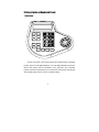
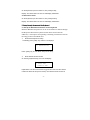
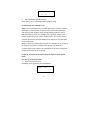
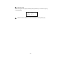
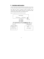
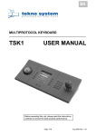
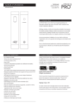
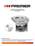
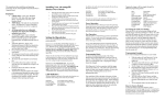
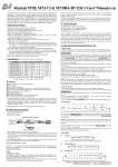
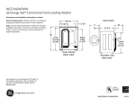
Contents
I. Description of Performance-------------------------------------------------------------1
1. Brief Introduction------------------------------------------------------------------------------------------2
2. Technical Data---------------------------------------------------------------------------------------------2
II. Description of Main Functions and Features--------------------------------------3
III. Description of Keyboard Panel-------------------------------------------------------4
1. Front Panel-------------------------------------------------------------------------------------------------4
2. Back Panel-------------------------------------------------------------------------------------------------6
IV. The Operation of the Keyboard------------------------------------------------------7
1. Select Camera/Decoder Address---------------------------------------------------------------------7
2. The control of Pan/tilt and Camera lens-------------------------------------------------------------7
3. Set up, preview and delete Preset Positions-------------------------------------------------------8
4. Enter/Exit Camera Menu--------------------------------------------------------------------------------8
5. Operations through the Menu of the Keyboard----------------------------------------------------9
5.1 Set up the Baudrate and Protocol for the keyboard----------------------------------------9
5.2 Set up left and right limiting positions for Speed Dome and start the Left&right
Scan-------------------------------------------------------------------------------------------------------11
5.3 Set up, activate and close Home Position function of the Speed Dome------------12
5.4 Set up and run the Tour Group of Speed Dome-------------------------------------------13
V. Installation and Connection-----------------------------------------------------------18
-1-
I. Description of Performance
1.Brief introduction
The controlling keyboard can be used to control matching terminal
devices directly such as high/constant-speed dome cameras, decoders, etc.
The electric port between the controlling keyboard and the receiving terminal
is EIA/RS – 485, which enables the keyboard to control as many as 128
speed dome cameras or other terminals within a maximum communication
range of 1.5 Km.
2. Technical Data
Power supply
DC12V
500mA
Power adaptor provided
AC220V±10%
Communication mode for connection
RS-485 for the connection with mainframe;
50/60HZ switch to DC12V 500mA
RS-485 bus mode for the connection with controlling devices.
Baud rate of communication
1200/2400/4800/9600/19200 BIT/S
Distance of communication
1500M (0.5MM twisted-pair)
Dimension
202(L)× 168(W)× 48(H)mm
Ambient Temperature
-10℃~60℃
Relative Humidity
≤90%RH
-2-
II. Description of Main Functions and Features
1. Photoelectric insulated RS485 controlling mode is adopted for the output of
the keyboard, which provides strong anti-jamming and long-distance
transmission.
2. The keyboard can control up to 128 Speed Domes or Decoders etc
terminal devices. The address of the Speed Domes or Decoders can be set
within the range of: 1~255.
3. Variable-speed operation can be applied to the built-in Pan/tilt of the Speed
Dome through the keyboard.
4. Lens zooming, focus and iris can be manually controlled through the
keyboard.
5. Manually or automatically control can be applied to Speed Dome through
the keyboard.
6. Joint-control can be realized by using the DVR keyboard together with one
DVR mainframe or embedded hard disk VCR.
7. Preset positions can be set up and previewed in Speed Dome through the
keyboard.
8. Tour groups can be set up and run through the keyboard.
9. Left and right limiting positions can be set up and Left&right scan can be
run through the keyboard.
10. Home position can be set up, activated and closed through the keyboard.
-3-
III. Description of Keyboard Panel
1. Front Panel
IRIS+
IRIS-
FOCUS+
FOCUS-
ZOOM+
ZOOM-
EXIT
AUTO
PRESET
PRE
VIEW
F1/ON
F2/OFF
FUN
ACK
On the front panel of the DVR keyboard are variable-speed controlling
joystick, keys and LED digital displayer. The LED digital displayer shows the
state of the system and the information of the operation. The controlling
joystick controls the speed dome to move upwards, downwards, left and right
with variable-speed, and is used for manually locating.
-4-
Instructions:
[CAM]
camera channel selection/confirmation
[PRESET]
preset position setup
[PREVIEW]
preset position previewing
[0] —[9]
numeral keys
[CLEAR]
clear key
[AUTO]
automatic left&right scan (ON/OFF)
[F1/ON]
Ancillary switch ON
[F2/OFF]
Ancillary switch OFF
[IRIS+]
Iris wider
[IRIS-]
Iris narrower
[ZOOM+]
[ZOOM-]
[FOCUS+]
[FOCUS -]
[FUN]
Zoom ratio higher
Zoom ratio lower
Focus farther
Focus nearer
Function key
[ACK]
Acknowledge key
[EXIT]
Exit key
-5-
2. Back Panel
Figure:
485output
485输出
485input power
485输入 电源
power
B A B A
-极
+极
Power supply outlet: connecting external DC12V power.
Communication outlet: RS-485 output outlet connects with the RS-485 outlet
of the decoder, RS-485 input outlet connects with the outlet of DVR
mainframe or built-in hard disk VCR.
-6-
IV. Operation of the Keyboard
1.
Select Camera/Decoder Addresses:
On the keyboard, press the number N, then press CA M.
Display: New “N” value will be displayed on the CAM section of the LCD
displayer
Remarks: N- speed dome camera number, range: 1~255
Function: Select the address of the Speed Dome or Decoder that is desired
to be controlled, the Speed Dome or Decoder corresponding with the value N
is to be under control.
2. The control of Pan/tilt and Camera lens
2.1 Lens zoom for close-up image: [ZOOM+]
2.2 Lens zoom for panoramic image: [ZOOM-]
2.3 Lens focus farther: [FOCUS+]
2.4 Lens focus nearer: [FOCUS-]
2.5 Iris wider: [IRIS+]
2.6 Iris narrower: [IRIS-]
2.7 Automatic switch: [AUTO] on/off cyclical key
2.8 Brush: on/off: Press numeral key “1” then press key “F1/ON” to switch on;
press numeral key “2” then press key “F2/ON” to switch off
2.9 Light: on/ff, press numeral key “2”,then press key “F1/on” to switch on;
press numeral key “2”, then press key “F2/on”to switch off.
2.10 The direction and speed of the pan/tilt movement can be freely
controlled through the variable-speed controlling joystick. The speed of
pan/tilt movement depends on the operating angle of the controlling joystick,
-7-
changing the slope angle of the joystick will adjust the movement speed.
Display: Related operation information will be displayed on the DATA section
of the LCD.
3. Set up, preview and delete Preset Positions
3.1 Set up Preset Position:
Operate the joystick on the keyboard to move the camera to the position
desired to be set as Preset Position, input Preset Position No. N. then press
[PRESET]
Display: The DATA section of the LCD will display “PRESET”
Remarks: N- preset position number, range: 1~255
Function: store the present position as the “N” position
3.2 Preview Preset Position:
On the keyboard, input Preset Position No. N. then press [PREVIEW]
Display: The DATA section of the LCD will display “PREVIEW”
Remarks: N—preset position number, range: 1~255
Function: Switch the camera to position number N
3.3 Delete Preset Position :
On the keyboard, input Preset Position No. N. then press [EXIT]
Display: The DATA section of the LCD will display “DELPRE”
Remarks: N- preset position number, range: 1~255
Function: Delete the stored preset position number N
4. Enter/Exit Camera Menu
4.1 Enter camera menu:
-8-
On the keyboard, input the number 3, then press [F1/ON]
Display: The DATA section of the LCD will display “MENUON”
4.2 Exit camera menu
On the keyboard, input the number 3, then press [F2/OFF]
Display: The DATA section of the LCD will display “MENUOFF”
5. Setup through the menu of the Keyboard
5.1 Set up the Baudrate and Protocol for the Keyboard
Different Baudrate and protocol can be set for different channel through
the Keyboard. When the keyboard switch dome camera/decoder
addresses, it will output corresponding controlling instructions based on
the setup protocols and Baud rates.
①
Enter Baud rate/protocol setup
Continually press “[FUN]” key until the LCD displays:
1)
Keyboard Setup
Press “[ACK]” key to enter Baud rate/protocol setup.
②
Enter desired camera number
On entering keyboard setup, the LCD will display:
1. Please Input
Camera No.:888
Explanations: The above information suggests the User enter the camera
number for Baud rate and protocol setup. The default camera number is
-9-
“888”, indicating that all the cameras have the same protocol and Baud rate.
If the User intends to set up different protocols and Baud rates, the default
“888” should be changed to corresponding camera number, ranging “1~128”.
③
Protocol and Baud rate setup
After setting up the camera number, press “ACK” key to enter protocol and
Baud rate setup, LCD displaying:
Protocol: PELCO_D
Baud Rate:2400
Explanation: The above information shows the present protocol and Baud
rate. Five kinds of protocols are optional for the User: PELO-D, PELCO-P,
PELCOD1, PELCOP1 and NEW. Press “[PREVIEW]”or “[PRESET]” key to
select desired protocol. After setting up the protocol, press “[F1/ON]” key to
switch the cursor to the state of Baud rate setup. Applicable Baud rates are:
1200、2400、4800、9600、19200BPS. Press “[PREVIEW]”or “[PRESET]” key
to select desired Baud rate.
④
Store the present setup of protocols and Baud rates
After setting up protocols and Baud rates, press “[F2/OFF]” key to store the
setup into the keyboard, and the keyboard will display the state of entering
new channel number.
⑤
Through Steps ②, ③, ④, different protocols and Baud rates can be set
up for special channels. When protocols and Baud rates for all the channels
are set up, please press “[EXIT]” key to exit the setup.
- 10 -
5.2 Set up Left/right Limiting positions, start and stop Left&right scan
5.2.1 Set up Left/Right Limiting positions for Speed Dome Camera
①
Enter left/right limiting positions setup
Repeatedly press “[FUN]” key until the LCD displays:
3)Limits Setup
Press “[ACK]” to enter the setup of left/right limiting positions
②
Left limiting position setup
When entering the setup of left/right limiting positions, the LCD will display:
3.0 Limits Setup
Limit:Left
Please press “[PRESET]” or “[PREVIEW]” key until the cursor shows “Left”,
then use the joystick to move the speed dome camera to the desired left
limiting position. Press “[F2/OFF]” key to store the present left limiting
position into the dome camera, LCD displaying:
Left
Set
③
Limit
OK!
Right limiting position setup
When entering the setup of left/right limiting positions, press “[PRESET]” or
“[PREVIEW]” key until the cursor shows “Right”, then use the joystick to move
the speed dome camera to the desired right limiting position. Press
“[F2/OFF]” key to store the present right limiting position into the speed dome,
LCD displaying:
- 11 -
Right
Limit
Set
④
OK!
Exit left/right limiting positions setup
Press “[EXIT]” key to exit left/right limiting positions setup.
5.2.2 Start and stop Left&right scan
Start: For Low-speed Dome and Constant-speed Dome cameras, press the
[AUTO] key on the keyboard, the Speed Dome camera will automatically
scan back and forth between the left and right limiting positions; well, for
High-speed Dome camera, the left&right scan is generally started by the
method of previewing some certain “preset position”, what “preset position”
should be previewed to start the left&right scan depends on the High-speed
Dome camera itself.
Stop: For all kinds of Speed Dome cameras, any operation on the joystick of
the keyboard can stop the Left&right scan. Well, for Low-speed and
Constant-speed Dome cameras, the Left&right scan can also be stopped by
pressing [AUTO] key for one more time.
5.3 Set up, activate and close Home Position function of the Speed
Dome
5.3.1 Set up the Home Position
①
Enter home position setup
Repeatedly press “[FUN]” key until LCD displays:
4)Home
Setup
- 12 -
②
Press “[ACK]” key to enter home position setup
③
Set up Home Position
When entering home position setup, LCD will display:
4.0 Home Setup
Home: current lie
Use the joystick to move the dome camera to the desired home position, and
press [F2/OFF] key to store the present home position into the speed dome,
LCD displaying:
④
Home
Lie
Set
OK!
Exit home position setup:Press “[EXIT]”key.
5.3.2 Activate and close Home Position function
5.3.2.1 Activate Home Position function:
On the keyboard, press the number 4, then press [F1/ON]
Display: The DATA section of the LCD will display “HOME ON”
5.3.2.2 Close Home Position function:
On the keyboard, press the number 4, then press [F2/OFF]
Display: The DATA section of the LCD will display “HOME OFF”
5.4 Set up and run the Tour Group of Speed Dome
5.4.1 Tour Group Setup
① Enter Tour Group Setup
Press “[FUN]” key to enter keyboard menu, making the LCD display:
- 13 -
2)
Speed
Dome
Group
Setup
Explanation: The above information indicates the setup of tour group
Press “[ACK]” key to acknowledge, and the LCD will display:
1.0 Speed
No.1
Dome
Group No.1
Explanation: The above information suggests the User enter the speed dome
camera address and tour group number.
②
Input the address of the Speed Dome Camera and set up the serial
number of the Tour Group
Operation procedure: Enter speed dome camera address from the numeral
key section (0-9), ranging “1~255”, then press “[F1/ON]” key to switch the
cursor to tour group setup, and enter tour group number, ranging “1~4”. For
example, if the User intends to set up the second tour group of dome camera
NO. 3, first enter number “3”, and press “[F1/ON]” key to switch the cursor to
tour group setup, and enter number “2”, the LCD displaying:
1.0 Speed
No.3
Dome
Group No.2
After setting up the dome camera address and tour group number, press
“[ACK]” key to enter the next setup.
③
Add Preset Position Number to the Tour Group
- 14 -
a)
Add Preset Position Number
Following the above step ② (Input the address of the Speed Dome Camera
and set up the serial number of the Tour Group), press “[ACK]” key to enter
the state of adding preset position number, the LCD displaying:
1.1Add position
Position No.:1
Explanation: The above information suggests the User enter preset position
number. Enter the preset position number from the numeral key section (0-9),
ranging “1~128”, then press “[ACK]” to acknowledge and enter the next step.
b)
Set up the parameters for the Preset Position
Following the above step, LCD displays:
1.2Position:XXX
Time:3
Explanation: The above information suggests the User set up the dwelling
time of the preset position, “XXX” is the preset position that was input in the
previous step.
Enter dwelling time of the preset position from the numeral key section,
ranging “1-255” seconds, then press “[ACK]” key to acknowledge, and a
preset position is successfully added to the tour group. The LCD display
returns to the state of preset position setup for further addition. Please repeat
the first and second steps to add all the preset positions required into the tour
group.
④
Store the Tour Group set up in Step ③ in the Speed Dome Camera
- 15 -
After all preset positions are successfully added to the tour group (as is
shown in Step ③ ), the display on the LCD returns to the state of inputting
next preset position number:
1.1Add position
Position No.:1
Now press “[F2/OFF]” key, the tour group set up in Step ③ will be stored in
the speed dome camera. LCD will return to the operation of Step ②.
⑤ Repeat the operations of Steps ②, ③, ④ to set up tour groups for all
speed dome cameras, then repeatedly press “[EXIT]” key twice to exit the
setup.
5.4.2 Run the Tour Group of the Speed Dome Camera
①
Enter the menu for running tour group
Repeatedly press “[FUN]”, until LCD displays:
5)Run
Group
Press “[ACK]” to enter the running of tour group
②
Enter tour group number
When entering the running of tour group, LCD will display:
5.0 Input Group
No.:1
Enter tour group number from the numeral key section, ranging “1-4”.
- 16 -
③
Run tour group
After entering the tour group number, press “[F2/OFF]” to run the tour group,
LCD displaying:
④
Run
Group
Group
No.:1
Return from the submenu of “Run Tour Group”. Press “[EXIT]” key.
- 17 -
V.
Installation and Connection
Attention: Please read the Manual carefully before installation and connection,
for any incorrect cable connection may cause permanent damages to the
units. Make sure power is switched off before connection and all
communication cables are shielded twisted pair. All communication cables
should avoid high-voltage cables or other jamming sources.
Figure for Keyboard, DVR and Camera Connection
- 18 -