1
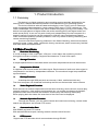
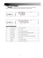
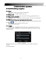
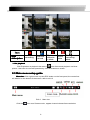
H.264 NETWORK Embedded DVR
User Manual
V1.1-4/8CH New Interface
Thank you for purchase our product
product.. Please read this user manual carefully to ensure
that you can use the device correctly and safely.
Attentions:
◆The DVR should be installed in a well-ventilated place,keep suitable space from
ground ,benefit for machine cooling,Be sure not to block its air vent.,keep away from heat
sources and high temperaturea environment。
◆Please keep the level installation of this product.should be avoid install at violently
shaking place(such as the back of car、motor above、high and rough luggage-rake).
◆For avoid short circuit cause fire or other damage,when wash the car please
prevent DVR(include camera and other parts) touch water and wet, the machine don’t have
waterproof.
◆The equipment consists of Precision Parts, please do not try to disassemble
or adjust any parts, if need maintenance, please contact the distributer or customer
service.
◆Please select the hard disk which commended by the manufacturers,suit
the DVR work requirement, to meet a long time largeamount of data read and write
requests, please purchase from the formal channels to ensure the hard disk quality .
◆This product can’t bear heavy weight, please do not place heavy object
or multi-layer laminated on the product .
Disclaimer:
The Company is do the best to make the contect correct and complete
during the preparation of this manual, if has any errors or omissions without any liability, the
company reserves the right to change any hardware and software mentioned inthis manual at
any time, and without explain beforehand. Thank you for choosing our products, please read
this manual carefully before use. Due to not according to the specified operating losses,
company will not assume any financial liability and legal responsibility.
CONTENT
1. Product Introduction................................................................................................... 2
1.1 Summary................................................................................................................2
1.2Main functions…………………………………………………………………. 4
1.3 Front panel buttons description......................................................................... 2
1.4 Rear panel diagram……………………………………………………………6
1.5 Remote control…………………………………………………………………7
2. Basic function operation............................................................................................ 2
2.1 On/off Switching navigation................................................................................2
2.2 Login…………………………………………………………………………….8
2.3 Main menu setup guide.......................................................................................2
2.4 Configuration management………………………………………………....10
2.4.1 Basic configuration......................................................................................2
2.4.2 Live configuration........................................................................................ 2
2.4.3 Record configuration...................................................................................2
2.4.4 Schedule configuration...............................................................................2
2.4.5 Alarm configuration………………………………………………….....16
2.4.6 Network configuration.................................................................................2
2.4.7 User management……………………………………………………...20
2.4.8 P.T.Z configuration.......................................................................................2
2.4.9 Advance configuration................................................................................ 2
2.5 Data retrieval........................................................................................................ 2
2.5.1 Time search.................................................................................................. 2
2.5.2 Event search................................................................................................ 2
2.6 Backup...................................................................................................................2
2.7 check information................................................................................................ 2
2.8 Disk management................................................................................................2
2.9 Upgrade.................................................................................................................2
2.10 Logoff................................................................................................................... 2
2.11 System shut down............................................................................................. 2
3
1. Product Introduction
1.1 Summary
This device is a digital monitoring and recording product specially designed for the
security field. It adopts standalone processor and standalone Linux operating system.
The device combines with the latest technologies in the IT field, such as video and
audio compression/decompression, large capacity HDD record, TCP/IP network etc.. The
code is embedded in the FLASH chip, which makes the system running more steadily. This
device has both features of digital video and audio recording(DVR) and digital video and
audio server(DVS). It can not only work locally and independently but also compose of a
powerful security monitoring net with networking. With the use of professional network
video surveillance platform (network) software, it can fully reflect its strong networking and
remote monitoring capability.
It can be used for the security protection in the fields of banking, telecommunications,
electronic power, justice, traffic, residential, factory, warehouse, water conservancy facilities
and other areas and departments.
1.2 Main Functions
�
Real
Real--time Monitoring
It is with analogue video output port, VGA port. It can realize the monitoring function
through the monitor or display. It supports simultaneous TV and VGA output.
�
Storage Function
It adopts special format to save data which cannot be tampered with and will be secured
�
Compression Method
It supports multi-channel audio and video signal. Each channel of audio and video signal is
compressed in real time by independent hardware. The sound and image keep stabilized
synchronization.
�
Backup Function
It backups through USB port(such as common U disk, mobile hard disk etc.)
The client computer can download and backup the files on the hard disk via the internet
�
back Function
Video Play
Playback
Each channel can realize independent and real-time recording, while retrieval, reverse play,
network monitoring, video search and download etc. can realize simultaneously.Multiple
playback modes: slow forward, fast forward, reverse play and frame-by-frame play.
When playing back the video, the exact time of the event can be displayed.
�
Network Operation Function
Through the internet, you can realize remote and real-time monitoring, remote video
search and playback, and remote PTZ control.
�
Communication Port
With RS485 port and PTZ control.
With standard Ethernet port, realizing network remote control function
�
PTZ Control
Support the PTZ decorder which communicates through RS485.
4
Can expand multiple decoding protocols, facilitating the realization of PTZ and dome
camera control.
�
Intelligent Operation
Mouse operation function.For the same settings on the menu, you can copy and paste
quickly.check equipment and accessories.
When you receive the product, please check the accessories are complete or not.
DVR accessories generally include: mouse, power lines and data lines.
1.3 Front panel buttons description
Statement: the front panel interface, button layout and type, real product shall prevail.
The front panel buttons Description:
Buttons on Front Panel
Red Color
1) IR Sensor
Sensor(Red
Color): IR receiver for the remote control.
2) LED Indicators
Indicators: Shows status of alarm, rec, power,link,HDD.
3) Playback
Playback: During playback, press the following:
•
: Increase reverse playback speed 1X, 2X, 4X
•
: Press to freeze playback to one frame, then press again to advance
frame-by-frame
• : Press to start playback
•
: Press to slow playback speed by 1/2, 1/4, 1/8
•
: Press to increase forward playback speed 1X, 2X, 4X
4) MENU/ OK
OK: Press to open/close the main menu.or confirm.
5) Navigation: Press the Navigation buttons to perform the following:
•: In menus, press to confirm selections; in PTZ mode, press to change the
navigation buttons to control the connected PTZ camera (not included)
•
: Press to move cursor up; in PTZ mode, press to pan camera up
•
: Press to move cursor down; in PTZ mode, press to pan camera down
•
: Press to move cursor left; in PTZ mode, press to pan camera left
•
: Press to move cursor right; in PTZ mode, press to pan camera right
6) USB
USB: Connect a USB flash drive to the top port for data backup and firmware
upgrades connect a USB mouse to the bottom port.
5
1.4 Rear panel diagram
Statement: the rear panel interface, button layout and type, real product shall
prevail.,below rear panel picture may be different with the actual panel.
Connectors on Rear Panel
Panel:
6
1.5 Remote control
In device operation, the enter key on remote control has the same function as left
click of the mouse.
The remote control is the secondary input device
For navigating the system’s interface.
To use the remote control:
1..STANDBY
STANDBY: When DVR on, constantly press the
RED button on the top for 3 seconds, the DVR will
be in standby status.Under standby mode, press
one time for immediate start.
2. LOGIN/LOCK
LOGIN/LOCK: If "Security" has been enabled in the
Setup menu, press to open the user password login
screen.
3. Number/Channel buttons
buttons: While in menus,
press buttons 0~9 to enter values; during live
viewing, press to view channels in full-screen.
4.
: Press to switch between quad and
split-screen displays.
5. MENU
MENU: Opens the main menu.
6. PTZ
PTZ: Press to open the PTZ control window.
7. EXIT
EXIT: Close menu windows.
8. Navigation/OK
Navigation/OK:
•
: Move cursor in menus up;
•
: Move cursor in menus right;
•
: Move cursor in menus left;
•
: Move cursor in menus down;
• OK
OK: In menus, press to confirm selections; during
playback and preview, press to view system information
9. +/ - : In menus, press to adjust values.
10. RECORD
RECORD: Press to start manual recording.
11. STOP
STOP: Press to stop manual recording.
12. EXTRA
EXTRA: For the future use.
13. Playback controls
controls:
•
: Increase reverse playback speed 2X, 4X, 8X
• : Press to start playback
•
: Press to increase forward playback speed 2X,
4X, 8X
•
: Press to slow playback speed by 1/2, 1/4, 1/8
•
: Press to freeze playback to one frame,
then press again to advance frame-by-frame
TIP
TIP: When using the remote
control to enter password
and camera titles, select the
field using the navigation
buttons, press ENTER, and
then press the number
buttons.
Check whether there is fluorescent light being used in the nearby
For the convenience of readers read and quick queries, the following
sections with a example of 4-channel digital hard disk recorders to introduce the
details, and pictures are base on this model, other model’s operation interface are
the same except channel and frame rate, Corresponding parameter to the same
settings, individual parameters can be directly and so on.
7
2. Basic function operation
2.1 On/off Switching navigation
2.1.1 Start
Before start,Please ensure all parts connected well!
Power on
Equipment start,POWER indicator light is red.
2.1.2 Power off
User can power off the device by using remote controller、keyboard and mouse.
2.1.3 By remote controller:
Press Power button, the Shut down window will appear, click OK, the unit will power
off after a while.
2.1.4 Disconnect the power by keyboard and mouse
mouse:
Step1: enter into Menu, then select “System Shut Down” icon, the Shut down window
will appear
Step2: click OK, the unit will power off after a while.
Step3: disconnect the power
2.2 Login
Equipment start ,【POWER】indicator light bright. initial password is blank. After
equipment start press 【MENU】key on panel or press right key on mouse, trun to login
interface as below:
Pic2-1 User login
After Input matching user name and password,you can enter system to setup and
operation.
Live preview interface:
8
Icon
Sign
description
recording
Manual
record
Motion
detectio
n state
Alarm
state
Timing
recording
state
� Live playback
Click Playbutton to playback the record
enter fast record playback: as lelow
picture: User can do concrete operation by click the buttons on screen.
2.3 Main menu setup guide
Menu bar: Click right mouse or press ESC button on the front panel, the control bar
will display on the bottom of the screen, refer to pic2-2
Pic2-2 Menu bar
Click the
icon near Screen mode , appear channel choose frame as below
9
Pic2-3 Channel choose
user could choose 1 channel from 1-4 to show live video.click
Click function menu
to save.
,will show dialogue frame as Pic 2-4;
Pic 2-4 Mian function
Click“configuration management”,display syswindows as pic2-5:
Pic 2-5 Configuration management”
Press MENU button on the front panel or the same button on remote control,
also cuold display the same window.
2.4 Configuration management
Configuration Management contains nine sub-menu: basic configuration,
on-site configuration, video configuration, recording plan, alarm configuration, network
configuration, user management, PTZ configuration and advanced configuration.
10
2.4.1 Basic configuration
Click“Basic configuration”,show window as pic2-6, The basic configuration
contains two sub-menu: system date and time
1) system
Pic 2-6 System
In this interface user can setup the device name, device ID, video format, Video
Output and language, Screensaver and so on. The definitions for every parameters display
as below:
Device name: It may display on the client end or CMS that help user to recognize the
device remotely.
Device number: Corresponding with the remote control number
Video format: two modes: PAL and NTSC. User can select the video format according
to that of camera.
Password check: Enable this option. user needs to input user name and password
can do corresponding operations with the relevant right in system configuration.
Show system time
time:choose display time in liveor not
Video output: the resolution of live display interface, range from: VGA800*600,
VGA1024*768, VGA1280*1024 and CVBS
Language
Language: setup the menu language:Simplified Chinese ,Traditional Chinese,
English,Japanese,German,Russian,French,Portuguese,Turkish,spanish,Italian,Polish,
Hungarian,Slovak,Vietnamese,greek
Click the "Default" button, the system restore the default things ;
Click the "Apply" button will save the above settings;
Click the "Exit"button to exit the current interface ,Tip to change the menu language
and video output, the device will restart.
2 ) Time & date
Pic 2-7 Time & date
11
Set the date format, time format time zone at the date and time "interface,; check the"
Keep synchronized with network time server "to update the network time server. You can
alsomanually adjust the system time。
Note: The system default is GMT time zone, please choose GMT +8 in the time
zone drop-down frame.
Click the "Default" button, the system restore the default settings;
Click the "Apply" button will save the above settings;
Click the "Exit"button to exit the current interface.
2.4.2 Live configuration
Live configuration
Click“Live
configuration”,enter window as pic2-8
Live configuration includes two submenus : live and mask
2.4.2.1 Live configuration
Pic 2-8 Live configuration
Note: Click Camera Name to see a soft keyboard. User can choose
different character format to input..
Tick off camera name and click “Setting” button to display a window as below:
Pic 2-9 Live-color adjustment
In this interface, user can adjust brightness, hue, saturation and contrast in live; click
“Default” button to resort default setting, click “OK” button to save the setting.
user can setup all channels with same parameters, please tick off “all” and then do relevant
setup.
2.4.2.2 Mask
Private mask. User can setup private mask area on the live image picture,
12
Pic 2-10 Mask
Setup mask area: click Setting button, enter into live image to press left mouse and
drag mouse to set mask area, refer to below picture. Click Apply button to save the setting.;
Delete mask area: select a certain mask area, click left mouse to delete that mask
area, click Apply button to save the setting.
Live image mask area
2.4.3 Record configuration
Record configuration
Click“Record
configuration”
,enter window as pic2-11:
Record configuration includes four sub menus: start, record bit rate, Character
overlay. recycle record.
13
2.4.3.1 Start
Pic 2-11 Start
Tick off record channel, channel audio.
User can setup all channels with same parameters, tick off “All”, then to do relevant
setup.
Click “Default” button to resort default setting; click “Apply” button to save the setting;
click “exit” button to exit current interface.
Video parameters instruction
Parameter
start
audio
Meaning
Every channel record switch
Start use the channel record audio
2.4.3.2 Record bit rate
Pic 2-12 Record bit rate
Setup rate, resolution, quality, encode and max bit stream
User can setup all channels with same parameters, tick off “All”, then to do relevant
setup.
Click “Default” button to resort default setting; click “Apply” button to save the setting;
click “Exit” button to exit current interface.
14
2.4.3.3 Record stream introduce
Parameter
Meaning
Fps
Range from 1-30(NTSC)1-25(PAL)
Resolution
Support D1、CIF
The higher the value is, the clearer the
Recorded image is. Six options:lowest,
lower, low, medium, higher and highest.
Support CBRand VBR
Select range: 16Kb、32Kb、64 Kb、
128 Kb、256 Kb、512Kb、640Kb、768Kb、
1024Kb、1536Kb、2048Kb
Quality
Coding
Max stream
:User can overlap the channel name and time stamp on video.
Stamp
Stamp:
Pic 2-13 Character overlay
Tick off camera name, time stamp; click Setting button, and then user can use cursor
to drag the camera name and time stamp in random positions. Please refer to below Figures
User can also setup all channels with same parameters.
Click “Default” button to resort default setting; click “Apply” button to save the setting;
click “Exit” button to exit current interface
2.4.3.4 Recycle record
Tick off recycle record to enable the recycle record function. It will cover the earlier
recorded files and keep recoding when HDD is full; if disenabled, it will stop recording when
HDD is full. Note: general the image quality, frame rate and resolution parameters setting
higher, the more take up disk space.
Click “Default” button to resort default setting; click “Apply” button to save the setting;
click “Exit” button to exit current interface.
2.4.4 Schedule configuration
Schedule configuration includes two sub menus: schedule and motion.
2.4.4.1 Schedule
15
The volume means the seven days of a week from Monday to Sunday; the row
means 24 hours of a day. Click the grid to do relevant setup. Blue means checked area,
gray means unchecked area.
Pic 2-14 Schedule
Copy
Copy:User can apply the schedule setting of certain channel to other or all channels.
Just only select channel and click “Copy” button.
Click “Default” button to resort default setting; click “Apply” button to save the setting;
click “Exit” button to exit current interface.
2.4.4.2 Motion
Pic 2-15 Motion
The setup steps of motion are familiar with schedule
Note: the default schedule of motion detection is full-selected, that is, the color of
schedule setting interface is blue..
2.4.5 Alarm configuration
Alarm configuration includes five sub menus: sensor, motion, video loss and alarm
out.
2.4.5.1 Sensor
The hardware does not support.
2.4.5.2 Motion
Motion includes one sub menus: motion
1> Motion
16
Pic 2-16 Motion
Click start motion alarm and set alarm hold time,It refers to after close motion alarm it
delay to the preset setting time. Click alarm "Settings" button, show below window:
Pic 2-17 Alarm handling
Alarm configuration, trigger video alarm handling, linkage alarm handling
and sensor alarm handling trigger settings is same.
Click on "Regional Settings" button at Motion detection interface,trun to the
following window;
Pic 2-18 Motion detection - Regional Settings
At area Setting interface, users can drag the slider to adjust the sensitivity value (1-5),
the default value is 4, 1-5 sensitivity progressive increase. Sensitivity influenced by the color
of time (day or night), the users should adjust according to actual situation.click
set All locales for the detection region;click
click
icon,
icon,will clear setting detection region;
icon,save setting;click
button,exit from current interface.
User can setup all channels with same parameters, please tick off “all”, and then to do
17
relevant setup.
Click “Default” button to resort default setting; Click “Apply” button to save the setting;
click “Exit” button to exit current interface.
2.4.5.3 Video loss
Pic 2-19 Video loss
Click“alarm handling”button,turn to window as below:
Pic 2-20 Video loss - alarm handling
The setup steps of video loss trigger are familiar with alarm handling.
User can also setup all channels with same parameters,
。click “Apply” button to save
the setting; click “Exit” button to exit current interface.
Click “Default” button to resort default setting;
Disconnected from the network: when the network connection is disconnected, the system
will automatically sent E-mail to the user specified mailbox about the
network disconnected.
2.4.5.3 Alarm out
The hardware does not support.
2.4.6 Network configuration
Network configuration includes four submenus: network, sub stream, Email and other
settings.
2.4.6.1 Network
18
Pic 2-21 Network configuration
HTTP port
port:the default value is 80. If the value changed, user needs to add the port
number when typing IP address in IE address blank. IE set HTTP port to 82, IP address:
http://192.168.0.25 , user needs to input that address: http://192.168.0.25:82 into IE
browser.
Server port
port: data and image communication port NO. After selecting the "Obtain an
IP address automatically", the device will distribute IP address, subnet mask, and gateway
IP and DNS server.
Enable PPPoE to directly connect the DVR to internet via ADSL and then input the
user name and password; click TEST button to test the effectiveness of the relevant
information.
Click “Default” button to resort default setting;click “Apply” button to save the setting;
Click “Exit” button to exit current interface.
2.4.6.2 Network Sub stream
Pic 2-22 Network Sub strea
select fps, resolution, quality.,user can also setup all channels with same parameters.
click “Apply” button to save the setting; click “Exit” button to exit current interface.
network configuration-network.
Parameter
Meaning
FPS
Range from: 1-25
Resolution
Support CIF
Quality
The higher the value is, the clearer the record image. Six
options: lowest, lower, low, medium, higher and highest.
19
2.4.6.3 Email
Pic 2-23 Email
SMTP Server/Port: the name and port number of SMTP server..
Send address/password: sender’s email address/password.
Receive address: receiver’s email address。Here user can add at least three mail
addresses
Click Test button to test the validity of the mailbox.
Click “Default” button to resort default setting;click “Apply” button to save the setting;
click “Exit” button to exit current interface.
2.4.6.4 Other settings
Pic 2-24 Other settings
, password and host domain
Enable DDNS server: user needs to input user name,
name of the registered website, click TEST to test the effectiveness of the relevant
information. click “default” button to resort default setting; click “apply” button to save the
setting; click “exit” button to exit current interface.
Note
Note: the user select a domain name is bound by the Domain Name Service for DVR,
you must first landing the website of the ISP registered user name and password, and
then apply for a domain name for the server online. After the application is successful, the
user could enter the domain name to access the server in IE side.
2.4.7 User management
20
Enter User management , as below pic:
Pic 2-25 User management
Clicking Add button, a dialog box will pop-up as below:
Pic 2-26 General
1
General: Input user name, password; select user type, input the MAC address of
the PC; click OK button, this user will be added into the user list box; click Exit button to exit
the current interface.
2
Authority:
Pic 2-27 Authority:
In the authority interface, assign the definite operation right for that user.
In the user management interface, click Setup button to modify user name, user type
and binding PC MAC address.
Select the user that user wants to delete in the user list box and then click Delete
button to delete this user. click Change password button to modify the password and then
click Exit button to exit the current interface.
21
2.4.8 P.T.Z configuration
P.T.Z configuration includes two submenus: serial port and advance
2.4.8.1 serial port
Pic 2-28 Serial port
Click“Start”
,base on P.T.Z support Protocol to set Address, Baud rate,and Protocol。
User can setup all channels with same serial port parameters, please tick off “All”, and
then to do relevant setup. click “Default” button to resort default setting; click “Apply” button
to save the setting; click “Exit” button to exit current interface
Definitions and descriptions of serial port:
Parameter
Address
Baud rate
Protocol
Meaning
The address of the PTZ device
Baud rate of the PTZ device. Range form: 110, 300, 600, 1200,
2400, 4800, 9600, 19200, 38400, 57600, 115200, 230400,
460800, 921600.
Communication protocol of the PTZ device. Range from:,
PELCOP, PELCOP1, PELCOP5, PELCOD, PELCOD1, HY,
PHILIPS, SAMSUNG SHARP,SONY, SAMSUNG, PANASMIC ,
Control, etc…
2.4.8.2 Advance configuration
Pic 2-29 Advance
22
In the Advance interface, after clicking preset “Setting” button, a dialog box will
pop-up as below:
Pic 2-30 Preset point setting
In the preset set interface, click Setting button to see a window as below:
Pic 2-31 Preset setting
User can control the P.T.Z up, up left, down, right down, left , left down, right and up
right and stop rotating;can adjust the rotation speed of the PTZ, focus, focus and aperture;
choose preset arrange NO.Click Save button to save the settings,click
tool bar, right-key can remerge it;click
icon to hide the
icon to exit the current interface
In the preset interface, click OK button to save the setting; click Exit button to exit
current interface.
In the Advance interface, click cruise “Setting” button, a dialog box will pop-up as below:
Pic 2-32 Advance - cruise “Setting”
Click Add button to add cruise line(max 32 cruise line can be added)
;select a cruise
line and click Setup button, to see a window as below:
23
Click Add
Pic 2-33 Cruise set - preset pointsetting
icon,to set the speed and time of preset point; select a preset point and
click Delete
icon to delete that preset poin;click Modify icon
,to modify the setting of
a preset point;User can click those icons to adjust the position of preset point.top
、
up 、down and bottom 。Click Preview button to preview the cruise line and then click
OK button to save the setting. Next, click Exit button to exit current interface
Select a preset point in the cruise line list box and click Delete button to delete that
cruise line; click Clear all button to clear all cruise line from the list box; click OK button to
save the setting; click Exit button to exit current interface.
In the Advance interface, click track “Setting” button to pop up a dialog box as below:
Pic 2-34 Track setting
User can control the dome rotates up, up left, down, right down, left, left down, right
and up right and stop rotating. adjust the rotate speed and the value of zoom, focus and iris
of the dome;click Start Record button to record the move track of PTZ and click this button
again can stop record;click Start track button to play recorded track and click this button
again can stop play . The user can drag the slider to adjust the rate of P.T.Z movement.
Click
icon to hide the tool bar, right-key can remerge it; click
icon to exit the
current interface.
In the Advance interface, click “Default” button to resort default setting; click “Apply”
button to save the setting; click “Exit” button to exit current interface.
24
2.4.9 Advance configuration
Advanced settings include three sub-menu: factory settings, andimport / export and
exit.
1. Factory settings: all settings back to factory settings
2. Import / Export: Users can export data files to be backed up onremovable storage
devices, you can also import the specified data file from a removable storage device to a
DVR.
3. Exit: exit current interface
Pic 2-35 Advance configuration
25
Returned to the main menu, enter the data retrieval interface.
2.5 Data retrieval
Search configuration includes two submenus: Time Search, Event Search,
2.5.1 Time search
Step1:enter into Search configuration�Time Search; refer to below pic:
Pic 2-36 Time search
Step 2:Select the channel, the calendar date , the start time and end time
Step 3:click“Play” button, Playback will start from the set time bucket; click the
corresponding button on the screen to start concrete operations.
Pic 2-37 Playback buttons
2.5.2 Event search
Step1::enter into Search configuration�event search; refer to below pic.
26
Pic 2-38 Event search
Step2:After clicking Search button, the searched event information will displayed in the
event list box, double check a certain record file to playback.
Step3:User can select date, channel. Tick off Motion, Sensor or All accordingly to
search.
2.6 Backup
This unit supports backup by USB device,User also can make backup by IE browser
via internet
Step1: enter into backup configuration interface, as below pic:
Pic 2-39 Data backup
Step2: set the start & end time, select channels and click Search button to display the
searched data in the data backup list box.
Step3: checked a data file or tick off “All” to select all data files, click Backup button,。
Step4: in the backup information interface, user can check the relevant information of
backup files, storage type, save file type, etc. click Start button to starting backup.
27
2.7 Check information
Through this option, the user can check system information, system journal, network
information
System Information
Information::
Enter menu � view information � system information, in the interface user can view
the equipment and version information and relevant information
Log information
information::
Enter menu � View system information � Log information,in the interface users can
set the start & end time of log you want to view, select the type of log you want to
view and click the search button, searched the log information will be displayed in the log list
box.
Note: Users can export data files to be backed up on removable storage devices.
Network information
information::
Enter menu � view information � Network configuration,in the interface,Users
can view the relevant parameters of the network information .
2.8 Disk management
Enter menu � Disk management,In the interface, the user can view disk storage state,
also can choose to formatting the hard disk
Please format the hard disk before record ,Specific operation as below:.
Step1: enter into disk management interface, The system will pop up the Disk
Management window.
Step2: select a hard disk and click Format button to star format.;set the property of the
disk then click Apply button to save the setting.
Note: all recorded files in the hard disk will be lost after formatted.
2.9 Upgrade
Once have the new version, the user can choose to upgrade the panel and the
mianboard, can get upgraded software from the buyers, to upgrade the system.
Upgrade step
step:user needs to copy the upgrade software which get from vendor into
the USB storage device and then connect to the USB port. Enter Menu Upgrade,refresh list,
the upgrade software name is displayed in the upgrade list box, select that software and click
Upgrade button to start upgrading. System will automatically restart on the upgrade process,
Please wait for a while when the system is rebooted. Please don’t cut off power during
upgrading。This system supports the upgrade of the USB device but it must
be compatible with the USB device, need to reboot the system after the upgrade
completed, to take effect.
Note: If the upgraded software does not appeared in USB, usually the USB
devices are not compatible
28
2.10 Logoff
Enter Menu � Logoff
Logoff,Click Log off icon, The system will exit the current user login. If
user wants to log in again, click mian menu icon to enter into user name and password to
re-login.
2.11 System shut down
Click“system shut down”icon, shut down system.
29