1
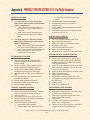
CRUISE-CLIMB TO LAUNCH ALTITUDE
NOTE: The following procedures can be performed on the
ground with the X-15 for Flight Simulator.
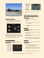
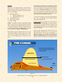
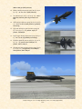
In the real world: During the cruise-climb to launch altitude, the pilot of the NB-52 carrier would start the timeto-go sequence and confirm with the launch operator that
the liquid oxygen top-off is satisfactory. The following
procedures would be performed at an altitude of between
35,000 to 45,000 feet.
1.
3500 psi.
2.
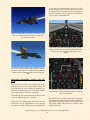
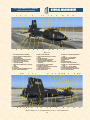
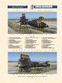
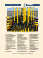
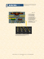
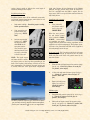
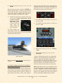
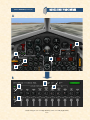
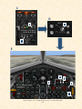
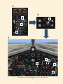
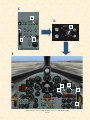
No. 1 generator switch [35, fig. 4-1; 45, fig. 4-2; 44,
fig. 4-3] – Move No. 1 generator switch momentarily
to RESET, then to ON.
3.
No. 1 generator out (amber) light [32, fig. 4-1; 41,
fig. 4-2; 42, fig. 4-3] – Check OFF.
4.
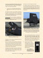
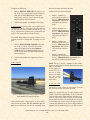
APU switch No. 2 [44, fig. 4-1; 54, fig. 4-2, 4-3] –
ON. As APU No. 2 comes up to speed, hydraulic
pressure will increase and then stabilize at 3000 to
3500 psi.
5.
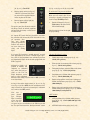
No. 2 generator switch [36, fig. 4-1; 46, fig. 4-2; 49,
fig. 4-3] – Move No. 2 generator switch momentarily
to RESET, then to ON.
6.
No. 2 generator out (amber) light
[39, fig. 4-1; 48, fig. 4-2; 47, fig 4-3]
– Check OFF.
7.
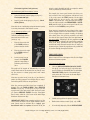
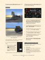
Stable platform power switch [9,
fig. 4-6, 4-7] – INT (up position).
8.
Service panel external power
switch [24, fig. 4-4] – OFF.
9.
Service panel external power
(yellow) light [25, fig. 4-4] – Check OFF.
Ram-air lever [28, fig. 4-11; 15, fig. 4-12] –
CLOSED.
PRELAUNCH
BEFORE COUNTDOWN
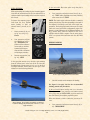
Before countdown, complete final cockpit check as follows:
1.
Ram-air lever [28, fig. 4-11; 15, fig. 4-12] – Check
CLOSED.
2.
Ventral arming switch [3, fig. 4-6, 4-7] – Check
ARM.
APUs:
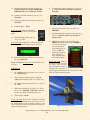
10. No. 1 generator voltmeter [33, fig. 4-1; 43, fig. 4-2;
45, fig. 4-3] – Check (200 volts, internal).
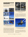
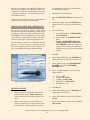
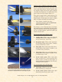
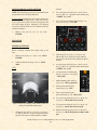
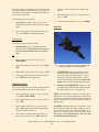
When the APUs are operating, steam should be observed
coming out of the APU exhaust pipes.
1.
APU switch No. 1 [26, fig. 4-1; 35, fig. 4-2; 67, fig. 43] – ON. As APU No. 1 comes up to speed, hydraulic
pressure will increase and then stabilize at 3000 to
11. No. 2 generator voltmeter [40, fig. 4-1; 50, fig. 4-2;
45, fig. 4-3] – Check (200 volts, internal).
12. Hydraulic pressure gauge [51, fig. 4-1; 60, fig 4-2;
36, fig. 4-3] – Check (both pointers, 3000 to 3500
psi).
Xtreme Prototypes X-15-1 for Flight Simulator, Version 1.0 – Utility Flight Manual
5-17