1
917.259940
Western
Auto
Operation and Service Instructions
Wizard Lawn Tractor
Stock Number
93-7167-5
Model Number
AYP7167A79
Factory Number
AYP7167A79
This
has a low
emiss!0n
0perates
differenUy product
from previously
built
engmes; engine
Beforewhich
you start
the engine,
read and understand this Owner's Manual.
Thank you for purchasing an American-built product.
i
WESTERN
AUTO TRACTOR
LIMITED
AYP7167A79
WARRANTY
Western Auto Supply Company warrants to the original retail purchaser that this product is free from defects in material or
workmanship and agrees to repair this product free of charge within these time periods from the date of purchase:
• 2 years, if the product is used for personal, family, or household use;
• 90 days, if the product is used for any other purpose such as commercial or rental use.
Excluded from this warranty are normal wear, maintenance, or mechanical adjustments which are not due to defects in
material or workmanship. Consult your owner's manual for help to maintain your product or make mechanical adjustments. Products
which have been altered, misused, abused, or repaired by other than aWestern Auto-authorized or manufacturer-authorized
service
facility are also excluded.
.
.
A rider or tractor battery which proves defe_:tive within 90 days wilt be replaced without charge. After 90 days but within 1
year from the date of purchase, Western Auto will replace the battery for a charge of 1/12 of the current retail price of the battery
for each full month between the date of purchase and the date of return.
Engines or transaxles are warranted by the engine or transaxle manufacturer which gives its own 2 year warranty and
provides service through its authorized service facilities. Seetheengineortransaxlewarrantyfordetaits.
Repairmaybearranged
through participating Western Auto stores.
For repair service return this product with proof of purchase date to a participating Western Auto store. This warranty gives
you specific legal rights and you may have other dghts that vary from state to state. If difficulty is encountered in having this warranty
honored, contact:
Western Auto Supply Company
Consumer Affairs Section of the General Service Department
2107 Grand Avenue, Kansas City, Missouri 64108
Telephone: 816 346-4411
CONGRATULATIONS
on your purchase of a new Tractor. It has been designed, engineered and manufactured
to give you the best possible dependability
and performance.
Should you experience
any problem you cannot easily
remedy, please contact your nearest authorized
service
center. We have competent, welt-trained technicians and
the proper tools to service or repair this tractor.
Please read and retain this manual.
The instructions will
enable you to assemble and maintain your tractor properly.
Always observe the "SAFETY
RULES".
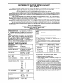
PRODUCT
SPECIFICATIONS
HORSEPOWER:
NUMBER
AYPTt67A79
SERIAL
NUMBER
DATE OF PURCHASE
THE MODEL AND SERIAL
PLATE UNDER THE SEAT.
NUMBERS
3.5 GALLONS
UNLEADED REGULAR
OIL TYPE (API-SF/SG):
See "ENGINE" in Customer
Responsibilities Section
OIL CAPACITY:
W/FILTER:
3.5 PINTS
W/O FILTER: 3.0 PINTS
SPARK PLUG:
GAP: .030")
CHAMPION RC12YC
VALVE CLEARANCE:
INTAKE:
EXHAUST:
GROUND SPEED (MPH):
Forward
tst
2rid
3rd
4th
5th
6th
Reverse
Western
Accessory
ON
Auto
A
Model
No.
No.
Grass Catcher
95-1031-4
CW42
48" Snow B_ade
95-2549-4F
LBD48
42" Snow Thrower
95-2626-0F
LSB42
CUSTOMER
Stock
RESPONSIBILITIES
Read and observe
.004" - .006"
.004" - .006"
WILL BE FOUND
YOU SHOULD RECORD BOTH SERIAL NUMBER AND DATE OF
PURCHASE AND KEEP IN A SAFE pLACE FOR FUTURE REFERENCE.
Optional
16.0
GASOLINE CAPACITY
AND TYPE:
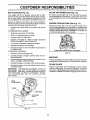
the safety rules.
Follow a regular schedule
using your tractor.
in maintaining,
caring for an
Follow the instructions under the "Customer Responsibil
ties" and "Storage" sections of this owner's manual.
1.1
1.5
2.3
3.5
4.4
5.7
1.7
WARNING: This tractort is equipped with an internal combustic
engine and should not be used on or near any unimproved tor'es
covered, brush-covered or grass-covered land unlessthe engine
exhaust system is equipped with a spark arrester meeting app
cable local or state laws (if any). If a spark arrester is used,
should be maintained in effective working order by the operate
TIRE PRESSURE:
FRONT:
REAR:
CHARGING
16 AMPS @ 3600 RPM
SYSTEM:
MODEL
14 PSI
10 PSI
BATTERY:
AMP/HR:
MIN. CCA:
CASE SIZE:
30
240
U1R
BLADE BOLT TOROUE:
30-35 FT. LBS.
tn the state of California the above is required by law (Sectk
4442 of the California Public Resources Code). Other states m;
have simitar laws. Federal laws apply on lederal lands.
SAFETY
RULES
Practices for Ride-On
Safe Operation
Mowers
IMPORTANT:
THIS CUTTING MACHINE IS CAPABLE OF AMPUTATING
HANDS AND FEET AND THROWING
FAILURE TO OBSERVE THE FOLLOWING SAFETY INSTRUCTIONS
COULD RESULT IN SERIOUS INJURY
GENERAL OPERATION
Read, understand, and follow all instructions in the manual
and on the machine before starting.
Only allow responsible adults, who are familiar with the
instructions, to operate the machine.
Clear the area of objects suchas
rocks, toys, wire, etc.,
which could be picked up and thrown by the blade.
Be sure the area is clear of other people before mowing. Stop
machine if anyone enters the area.
Never carry passengers.
Do not mow in reverse un]ess absolutely necessary. Always
look down and behind before and while backing.
Be aware of the mower discharge direction and do not point
it at anyone. Do not operate the mower without either the
entire grass catcher or the guard in place.
Slow down before turning.
Never leave a running machine unattended. Always turn off
blades, set parking brake, stop engine, and remove keys
before dismounting.
Turn off blades when not mowing.
Stop engine before removing grass catcher or unclogging
chute.
Mow only in daylight or good artificial light.
Do not operate the machine while under the influence of
alcohol or drugs.
Watch for traffic when operating near or crossing roadways.
Use extra care when loading or unloading the machine into
a trailer or truck.
II.
SLOPE OPERATION
Slopes are a major factor related to loss-of-control and
tipover accidents,which
can result in severe injuryordeath.
All slopes require extra caution.
If you cannot back up the
slope or if you feel uneasy on it, do not mow it.
DO:
Mow up and down slopes, not across.
Remove obstacles such as rocks, tree limbs, etc.
Watch for hales, ruts, or bumps.
Uneven terrain could
overturn the machine. Tall grass can hide obstacles.
Use slow speed. Choose a low gear so that you will not have
to stop or shift while on the slope.
Follow the manufacturer's
recommendations
for wheel
weights or counterweights to improve stability.
Use extra care with grass catchers or other attachments.
These can change the stability of the machine.
Keep all movement on the slopes slowand gradual Do not
make sudden changes in speed or direction.
Avoid starting or stopping on a slope. If tires lose traction,
disengage the blades and proceed slowly straight down the
slope.
OBJECTS,
OR DEATH.
IlL CHILDREN
Tragic accidents can occur if the operator is not alert to the
presence of children.
Children are often attracted to the
machine and the mowing activity.
Never assume that
children will remain where you last saw them.
Keep children outofthe mowing area and under the watchful
care of another responsible adult.
Be alert and turn machine off ff children enter the area.
Before and when backing, look behind and down for small
children.
Never carry children. They may fall off and be seriously
injured or interfere with safe machine operation.
Never allow children to operate the machine.
Use extra care when approaching blind corners, shrubs,
trees, or other objects that may obscure vision.
IV. SERVICE
Use extra care in handling gasoline and other fuels. They are
flammable and vapors are explosive.
Use only an approved container.
Never remove gas cap or add fuel with the engine
running. Allow engine to cool before refueling. Do not
smoke.
Never refuel the machine indoors.
Never store the machine or fuel container inside where
there is an open flame, such as a water heater.
Never run a machine inside a closed area.
Keep nuts and bolts, especially blade attachment bolts, tight
and keep equipment in good condition.
Never tamper with safety devices.
Check their proper
operation regularly.
Keep machine free of grass, leaves, or other debris build-up.
Clean oil or fuel spillage. Allow machine to cool before
storing.
Stop and inspect the equipment if you strike an object.
Repair, if necessary, before restarting.
Never make adjustments or repairs with the engine running.
Grass catchercomponents are subject to wear, damage, and
deterioration, which could expose moving parts or allow
objects to be thrown. Frequently check components and
replace with manufacturer's recommended parts, when necessary.
Mower blades are sharp and can cut. Wrap the blade(s) or
wear gloves, and use extra caution when servicing them.
Check brake operation frequently.
Adjust and service as
required.
Look for this symbol to point out important safety precautions.
It means
CAUTION!!! BECOMEALERT!!t
YOUR
SAFETY IS INVOLVED.
DO NOT:
Do not turnon slopes unless necessary, and then, turn slowly
and gradually downhill, if possible.
Do not mow near drop-offs, ditches, or embankments. The
mower could suddenly turn over it a wheel is over the edge
of a cliff or ditch, or if an edge caves in.
Do not mow on wet grass. Reduced traction could cause
sliding.
Do not try to stabilize the machine by putting your foot on the
ground.
Do not use grass catcher on steep slopes.
&
CAUTION: Always disconnect spark plug
wire and place wirewhere it cannot contact
spark plug in order to prevent accidental
starting when setting up, transporting,
adjusting or making repairs.
A0=WARNING
The engine exhaust from this product
contains chemicals known to the State of California to cause cancer, birth defects,
or other
reproductive
harm.
TABLE OF CONTENTS
SAFETY RULES .......................... ;................................. 3
PRODUCT SPECIFICATIONS ...................................... 2
CUSTOMER RESPONSIBILITIES ..................... 2, 14-17
WARRANTY ..................................................................
2
ASSEMBLY ................................................................
6-8
OPERATION .............................................................
9-13
MAINTENANCE SCHEDULE ...................................... 14
SERVICE AND ADJUSTMENTS ............................ 19-24
STORAGE ...................................................................
25
TROUBLESHOOTING ............................................
26-27
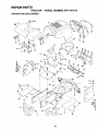
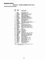
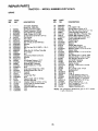
REPAIR PARTS - TRACTOR ................................. 30-47
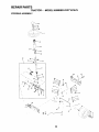
REPAIR PARTS - ENGINE .................................... 48-53
PARTS ORDERING/SERVICE ................ BACK COVER
INDEX
E
A
Accessories ...........................................
Adjustments:
Brake ............................................
Carburetor .:..................................
Mower
Front-To-Back .........................
Side-To-Side ...........................
Throttle Control Cable ..................
Air Filter, Engine ..................................
Air Screen, Engine ..............................
Assembly ............................................
5
21
24
20
20
23
17
17
6-8
B
Battery:
Charging ........................................
Cleaning .......................................
Starting with Weak Battery ...........
Storage ........................................
Terminals .....................................
Belt:
Motion Ddve
Removal/Replacement ............
Mower Belt(s)
Removal/Replacement ............
Blade:
Sharpening ...................................
Replacement ................................
Brake Adjustment ................................
7
16
22
25
16
21
21
15
15
21
C
Carburetor Adjustment ........................ 24
Controls, Tractor ................................. 10
Customer Responsibilities .............. !4-18
Engine:
Air Filter .................................... 17
Air Screen ................................ 17
Cooling Fins ............................. 1"7
Engine Oil ........................... 12,16
Fuel Filter ................................. 18
Spark Plug(s) ........................... 18
Tractor:
Battery ......................................
16
Blade ........................................
15
Lubrication Chart ...................... 14
Maintenance Schedule ............ 14
Tire Care .......................... 7,15,22
Transaxle ................................. 16
Cutting Height, Mower ......................... 11
O
Electrical:
|nterlecks and Relays ................... 23
Schematic .................................... 29
Wiring Diagram ............................ 30
Engine:
Air Filter ........................................
17
Air Screen .................................... 17
Cooling Fins ................................. 17
Oil Change ...................................
16
Oil Level .......................................
12
Oil Type ................................... 12,16
Preparation .................................. 12
Repair Parts ............................ 48-53
Starting ......................................... 13
Storage ........................................
25
F
Filter:
Air Filter ........................................
Fuel ..............................................
Fuel:
Type .............................................
Storage ........................................
Fuse ....................................................
P
Parking Brake .................................
10-11
Parts Bag ..............................................
5
Parts, Replacement/Repair
............ 30-42
Product Specifications ...........................
R
Repair Parts ...................................
12
25
23
Safety Rules ..........................................
Seat .......................................................
.................. 23
L
Leveling Mower Deck ..........................
Lubrication:
Chart ............................................
Engine ..........................................
Cold Weather Conditions ........ 12,16
Engine ..........................................
16
Storage ........................................
25
Ope ration .........................................
9-13
Operating Mower .................................
12
Options:
Accessories ....................................
2
Spark Arraster ........................... 2,40
17
18
H
Hood Removal/Installation
Oil:
20
14
16
M
Maintenance Schedule ....................... 14
Mower:
Adjustment, Front-to-Back ........... 20
Adjustment, Side-to-Side ............. 20
Blade Replacement ...................... 15
Blade Sharpening ........................ 15
Cutt{ng Height .............................. 11
installation ....................................
19
Operation .....................................
12
Removal .......................................
19
Mowing Tips ........................................
13
Muffler .................................................
18
Spark Arrester ........................... 2.40
30-4";
S
Service and Adjustments ............... 19-2,
Carburetor ....................................
2
Fuse .............................................
2
Hood Removal/Installation
........... 2
Motion Ddve Belt
Removal/Replacement
............ 2
Mower Belt(s)
Removal/Replacement
............ 2
Mower Adjustment
Front-to-Back .......................... _Side-to-Side ............................ _Mower Removal/Installation
......... 1
Tire Care ..............................
7,15,_Slope Guide Sheet ..............................
t
Spark Plug(s) ......................................
Specifications .......................................
Starting the Engine ........................ 12Steering Wheel .................................
6,
Stopping the Tractor ............................
Storage ................................................
T
Throttle Control Cable Adjustment ......
Tires ............................................
7,15
Troubleshooting Chart .................... 26
Transaxle ............................................
W
4
:
"
Warranty .............................................
Wiring Diagram ..................................
Wiring Schematic ...............................
CONTENTS
OF HARDWARE
Parts Bag contents shown full size
PACK
Parts packed separately
in carton
(1) Hex Bolt
3/8-16 x 1
Seat
©
Mulcher
Plate
!4::J
(1) Large Flat Washer
;4/'Steering
Boot
Steenng
Wheel
(1) Lockwasher 3/8
@
(1) Locknut 5/16-18
(1) Hex Bolt 5/16-18 x 1-1/4
d
(1) Hex Bolt
1/2-13 x 1
(1) Shoulder
Bolt 5/16-18
Parts Bag
Manual
Parts bag contents
not shown full size
(2) Gauge
Wheels
(2) Shoulder
Bolts
(2) CenterLockNuts
3/8-16
(2) Lock Washers
#10
x 5/8
2) Screws
_
_)_ZE_CCC_[Z]
Nuts
#10 _
(2) WeLd
_
1/4-20 x 3/4
(2) HexBolts
@
Nuts
(2) Hex
1/4 -20
_
Washers
(2) Lock
1/4
©
©
(1) Lock Washer 1/2
17/32 x 1-3/16 x 12 Gauge
Extension
Shaft
Steering
(2) Latch
Hook
Assemblies
(2) Keys
_
9/32
x 518 x 16
(2) Washers
Gauge
Slope Sheet
5
(2) Washers
3/8 x 7/8 x 14 Gauge
Steering Wheel
Adapter
Steering
Wheel Insert
ASSEMBLY
Your new tractor has been assembled at the factory with exception of those parts left unassembled for shipping purposes
To ensure safe and proper operation of your tractor all parts and hardware you assemble must be tightened securely. Us_
the correct tools as necessary to insure proper tightness.
TOOLS REQUIRED
FOR ASSEMBLY
A socket wrench set will make assembly easier. Standard
wrench sizes are listed.
(1) 3/4" Socket w/drive rachet
(2) 7/16" wrenches
Phillips Screwdriver
(2) 1/2" wrench
(1) 9/16" wrench
Tire pressure gauge
Utility knife
When right or left hand is mentioned in this manual, it
means when you are in the operating position (seated
behind the steering wheel).
TO REMOVE TRACTOR FROM CARTON
UNPACK
CARTON
Remove all accessible loose parts and parts cartons
from carton (See page 5).
Cut, from top to bottom, along lines on all four corners
of carton, and lay panels flat.
Check for any additional loose parts or cartons and
remove.
IMPORTANT:
CHECK FOR AND REMOVE ANY STAPLES
IN SKID THAT MAY PUNCTU RE TIRES WHERE TRACTOR
IS TO ROLL OFF SKID.
BEFORE ROLLINGTRACTOR
ATrACH
STEERING
WHEEL
OFF SKID
(See Fig. 1)
ASSEMBLE EXTENSION SHAFT AND BOOT
Slide extension shaft onto lower steering shaft. Align
mounting holes in extension and lower shafts and
install 5/16 hex bolt and Iocknut. Tighten securely.
IMPORTANT: TIGHTEN BOLT AND NUT SECURELY TO
18-22 FT. LBS TORQUE.
FIG. 1
Place tabs of steering boot over tab slots in dash and
push down to secure.
TO ROLL TRACTOR OFF SKID (See Opera
tion section for location and function
of con
trois)
INSTALL STEERING WHEEL
Position front wheels of the tractor so they are pointing
straight forward.
•
Slide steering wheel adapter onto steering shaft exte nslon.
Position steering wheel and sleeve assembly so cross
bars are horizontal (left to right) and slide onto adapter.
Assemble large flat washer, 3/8 lock washer, 3/8 hex
bolt and tighten securely.
•
•
Snap steering wheel insert into center of steering
wheel.
Remove protective plastic from tractor hood and grill.
IMPORTANT:
CHECK FOR AND REMOVE ANY STAPLES
IN SKID THAT MAY PUNCTURE TIRES WHERE TRACTOR
iS TO ROLL OFF SKID.
6
Press lift lever plunger and raise attachment lift lever t
its highest position.
Release parking brake by depressing clutch/brak
pedal.
Place gearshift lever in neutral (N) position.
Roll tractor backwards oft skid.
Remove banding holding discharge guard up again_
tractor.
ASSEMBLY
HOW TO SET UP YOUR TRACTOR
INSTALL
CONNECT
Adjust seat before tightening adjustment bolt,
•
Remove cardboard packing on seat pan.
Place seat on seat pan and assemble shoulder bolt.
Assemble adjustment bolt, lock washer and flat washer
loosely. Do not tighten.
•
Tighten shoulder bolt securely.
•
Lower seat into operating position and sit on seat.
Slide seat until a comfortable position is reached which
allows you to press clutch/brake pedal all the way
down.
Get off seat without moving its adjusted position.
Raise seat and tighten adjustment bolt securely.
BATTERY
(See Figs. 2 and 3)
CAUTION: Do not short battery terminals, Before connecting battery, remove metal bracelets,
wristwatch
bands, rings, etc.
Positive terminal must be connected
first to prevent sparking from accidental grounding.
•
•
Remove cardboard packing from seat pan and lift seat
pan to raised position.
Open battery box door.
Remove terminal protective caps and discard.
If this battery is put into service after month and year
indicated on label (label located between terminals)
charge battery for minimum of one hour at 6-10 amps.
First connect RED battery cable to positive (+) terminal
with hex bolt, flat washer, lock washer and hex nut as
shown. Tighten securely.
Connect BLACK grounding cable to negative (-) terminal with remaining he× bolt, flat washer, lock washer
and hex nut. Tighten securely.
Close battery box door.
POSITIVE
(RED)
CABLE
SEAT (See Fig. 4)
SEA
S.O LOER
.DISCARD TERMINAL
CAPS
BOLT
_
_
\\\
_LOCKWASHER
FIG. 4
HEX NUT
LOCK WASHER
CHECK TIRE
PRESSURE
The tires on your tractor were ove rinflated
shipping purposes. Correct tire pressure
best cutting performance.
Reduce tire pressure to PSI shown
SPECIFICATIONS" on page 2 of this
FLAT
WASHER
For best cutting results, mower housing should be properly
leveled. See "TO LEVEL MOWER HOUSING" in the
Service and Adjustments section of this manual.
CABLE
FIG. 2
Open battery box door for:
•
Inspection for secure connections
ware).
inspection for corrosion.
•
Testing battery.
•
Jumping (if required).
•
Periodic charging.
in "PRODUCT
manual.
CHECK DECK LEVELNESS
HEX
BOLT
NEGATIVE (BLACK)
at the factory for
is important for
CHECK FOR PROPER POSFFION OF ALL BELTS
See the figures that are shown for replacing motion and
mower blade drive belts in the Service and Adjustments
section of this manual. Verify that the belts are routed
correctly.
(to tighten hard-
CHECK BRAKE
SYSTEM
After you learn how to operate your tractor, check to see
that the brake is properly adjusted. See "TO ADJUST
BRAKE" in the Service and Adjustments section of this
manual.
SEAT
PAN
ASSEMBLE
BOX OOOR
FIG. 3
7
GAUGE
WHEELS
TO
MOWER
DECK (See Fig. 5)
Assemble gauge wheels with tractor on a flat level surface.
Adjust mower to desired cutting height (See '`TO ADJUST MOWER CUTTING HEIGHT" in the Operation
section of this manual).
With mower in desired height of cut position, gauge
wheels should be assembled so they are slightly off the
ground. Instal] gauge wheel in appropriate hole with
shoulder bolt, 3/8 flat washer, and 3/8-16 Iocknut and
tighten securely.
Repeat for opposite side installing gauge wheel in
same adjustment hote.
ASSEMBLY
GAUGE WHEEL
MOUNTING
BRACKET
_
TO CONVERT TO BAGGING
DISCHARGING
\
OR
Simply remove mulcher plate and store in a safe place
Your mower is now ready for discharging or installation c
optional grass catcher accessory.
DEFLECTOR
3/8-16
LOCKHUT
3/8 FLAT WASHER "_'
_P' _1
GAUGE WHEEL _\
SHOULDER
BOLT
_"
FIG. 5
INSTALL MULCHER
(See Figs. 6 & 7)
•
PLATE
Install two latch hooks to mulcher plate using screw,
washer, lock washer, and weld nut as shown.
LATCH
HOOKS
NOTE: Pre-assemble weld nut to latch hook by inserting
weld nut from the top with hook pointing down.
FIG. 7
•
Tighten hardware securely.
•
Raise and hold deflector shield in updght position.
•
•
Place front of mulcher plate over front of mower deck
opening and slide into place, as shown.
Hook front latch into hole on front of mower deck.
•
Hook rear latch into hole on back of mower deck.
,/CHECKLIST
BEFORE YOU OPERATE AND ENJOY YOUR NEt
TRACTOR, WE WISH TO ASSURE THAT YOU RECEIV
THE BEST PERFORMANCE AND SA TISFA C TION FRO_
THIS QUALITY PRODUCT.
PLEASE REVIEW THE FOLLOWING CHECKLIST:
CAUTION: Do not remove discharge
guard from mower. Raise and hold
guard when attaching mulcher plate
and allow it to rest on plate while in
operation.
WELD NUT FROM THE TOP
WELD
NUT.
HOOK POINTS DOWN
,/
All assembly instructions have been completed.
,/
No remaining loose parts in carton.
,/
Battery is propedy prepared and charged.
1 hour at 6 amps).
,/
Seat is adjusted comfortably and tightened securel_
,/
All tires are propedy inflated. (For shipping purpose:
the tires were ovednflated at the factory).
/
Be sure mower deck is properly leveled side-to-sid_
front-to-rear for best cutting results. (Tires must t:
properly inflated for leveling).
,/
Check mower and drive belts. Be sure they are rout_
properly around pulleys and inside all belt I_eepers:
LOCK
WASHER
\
,/
HOOK
Check wiring. See that aft connections are still secu
and wires are properly clamped.
WHILE LEARNING HOWTO USE YOUR TRACTOR, PP
EXTRA A TTENTION TO THE FOLLOWING IMPORTAh
ITEMS:
WELD
NUT
,/
J
LATCH
HOOK"_-..
LOCK
WASHER
WASHER
/
WASHER
,/
MULCHER
PLATE
(Minimul
-_SCREW
FIG. 6
8
Engine oil is at proper level.
Fue_ tank is filled with fresh, clean, regular unleadc
gasoline.
Become familiar with all controls - their location at
function. Operate them before you start the engin_
Be sure brake system is in safe operating conditior
OPERATION
These symbols may appear on your tractor or in literature supplied with the product. Learn and understand their meaning.
f
BATTERY
CAUTION OR
WARNING
REVERSE
FORWARD
FAST
SLOW
ENGINE ON
ENGINE OFF
OIL PRESSURE
CLUTCH
LIGHTS ON
LIGHTS OFF
0
FUEL
k
!
m
MOWER LIFT
CHOKE
MOWER HEIGHT
DIFFERENTIAL
LOCK
PARKING BRAKE
LOCKED
UNLOCKED
R N H L
REVERSE
NEUTRAL
ATTACHMENT
CLUTCH ENGAGED
HIGH
LOW
ATTACHMENT
CLUTCH DISENGAGED
PARKING BRAKE
IGNITION
HYDROSTATIC FREE WHEEL
(Hydro Models only)
DANGER, KEEP HANDS AND FEET AWAY
9
OPERATION
KNOW YOUR TRACTOR
READ THIS OWNER'S
MANUAL
AND SAFETY RULES
BEFORE
OPERATING
YOUR
TRACTOF
Compare the illustrationswith your tractor to familiarize yourselfwith the locations ofvarious controls and adjustments. Saw
this manual for future reference.
IGNITION
SWITCH
AMMETER
LIGHT
SWITCH
POSITION
ATTACHMENT
CLUTCH LEVER
CHOKE
CONTROL
LIFT LEVER
PLUNGER
CLUTCH/BRAKE
PEDAL
LIFT LEVER
THROTTLE
CONTROL
PARKING
BRAKE
HEIGHT
ADJUSTMENT
KNOB
GEARSHIFT
LEVER
RG. 8
Our tractors conform to the safety standards of the American National Standards Institute.
ATTACHMENT CLUTCH LEVER: Used to engage the
mower blades, or other attachments mounted to your
tractor.
GEARSHIFT LEVER: Selects the speed and direction (
tractor.
A'B'ACHMENT LIFT LEVER: Used to raise and lower th
mower deck or other attachments mounted to your tracto
LIFT LEVER PLUNGER: Used to release attachment li
lever when changing its position.
LIGHT SWITCH POSITION: Turns the headlights on.
THROTTLE
CONTROL:
Used to control engine speed.
CLUTCH/BRAKE PEDAL: Used for declutching and braking the tractor and starting the engine.
AMMETER:
battery.
IGNITION SWITCH:
engine.
Indicates charging (+) or discharging (-) of
PARKING BRAKE:
brake position.
Locks clutch/brake
Used for starting and stopping tl-
HEIGHT ADJUSTMENT
cutting height.
pedal into the
CHOKE CONTROL:
10
KNOB: Used to adjust the mow,
Used when starting a cold engine
OPERATION
The operation of any tractor can result in foreign objects thrown into the eyes, which can
result in severe eye damage. Always wear safety glasses or eye shields while operating
your tractor or performing any adjustments or repairs. We recommend a wide vision
safety mask over the spectacles or standard safety glasses.
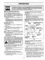
HOW TO USE YOUR TRACTOR
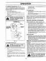
TO SET PARKING
TO MOVE FORWARD
(See Fig. 9)
BRAKE (See Fig, 9)
AND BACKWARD
The direction and speed of movement is controlled by the
gearshift lever.
•
Start tractor with clutch/brake pedal depressed and
gearshift lever in neutral (N) position.
•
Move gearshift lever to desired position.
•
Slowly release clutch/brake pedal to start movement.
IMPORTANT: BRING TRACTOR TO A COMPLETE STOP
BEFORE SHIFTING OR CHANGING GEARS. FAILURE
TO DO SO WILL SHORTEN THE USEFUL LIFE OF YOUR
TRANSAXLE.
Your tractor is equipped with an operator presence sensing
switch.
When engine is running, any attempt by the
operator to leave the seat without first setting the parking
brake will shut off the engine.
•
Depress clutct'dbrake pedal into full "BRAKE" position
and hold.
Place parking brake lever in =ENGAGED" position and
release pressure from clutch/brake pedal. Pedal should
remain in =BRAKE" position. Make sure parking brake
will hold tractor secure.
STOPPING
(See Fig. 9)
MOWER BLADES -
ATTACHMENT CLUTCH
"ENGAGED" POSITION
CHOKE
CONTROL
Move attachment clutch lever to "DISENGAGED" poo
sition.
GROUND DRIVE •
Depress clutch/brake pedal into full "BRAKE" position.
Move gearshift lever to neutral (N) position,
ENGINE -
"DISENGAGED"
POSITION
THROTTLE
CONTROL
"ENGAGED"
"BRAKE"
POSITION
NOTE:
Failure to move throttle control to slow (-=b)
position and allowing engine to idle before stopping may
cause engine to =backfire".
Turn ignition key to "OFF" position and remove key.
Always remove key when leaving tractor to prevent
unauthorized use.
"DISENGAGED"
POSITION
•
Never use choke to stop engine.
NOTE: Under certain conditions when tractor is standing
idle with the engine running, hot engine exhaust gases may
cause "browning" of grass. To eliminate this possibility,
always stop engine when stopping tractor ORgrass areas.
CLUTCH/BRAKE
PEDAL"DRIVE"
POSITION
USE
THROTTLE
CONTROL
HEIGHT
ADJUSTMENT
KNOB
FIG. 9
I
TO
BRAKE
POSITION
GEARSHIFT
LEVER
Move throttle control to slow (,.am,)position.
CAUTION: Always stop tractor completely, as described above, before leaving the operator's position; to empty
grass catcher, etc.
LEVER
TO ADJUST
|
I
(See
MOWER
CUTTING
HEIGHT
Fig, 9)
The cutting height is controlled by turning the height adjustment knob in desired direction.
•
(See Fig. 9)
Turn knob clockwise (F_) to raise cutting height.
Turn knob counterclockwise
height.
Always operate engine at full throttle.
•
Operating engine at less than full throttle reduces the
battery charging rate.
Full throttle offers the best bagging and mower performance.
(Ir--_) to lower cutting
The cutting height range is approximately 1-1/2" to 4". The
heights are measured from the ground to the blade tip with
the engine not running. These heights are approximate
and may vary depending upon soil conditions, height of
grass and types of grass being mowed.
TO USE CHOKE
CONTROL
(See Fig. 9)
Use choke control whenever you are starting a cold engine.
Do not use to start a warm engine.
To engage choke control, pull knob out. Slowly push
knob in to disengage.
The average lawn should be cut to approximately 2-1/2
inches during the cool season and to over 3 inches
during hot months. For healthier and better looking
lawns, mow often and after moderate growth.
For best cutting performance, grass over 6 inches in
height should be mowed twice. Make the first cut
relatively high; the second to desired height.
11
OPERATION
TO OPERATE
MOWER (See Fig. 10)
•
Your tractor is equipped with an operator presence sensing
switch. Any attempt by the operator to leave the seat with
the engine running and the attachment clutch engaged will
shut off the engine.
Select desired height of cut,
Lower mower with attachment lift control.
To restart movement, slowly release parking brake anc
clutch/brake pedal.
Make all turns slowly.
TO TRANSPORT
•
Raise attachment lift to highest position with attach"
ment lift control.
Start mower blades by engaging attachment clutch
control.
•
When pushing or towing your tractor, be sure gearshif
lever is in neutral (N) position.
TO STOP MOWER BLADES - disengage attachment
clutch control.
•
Do not push or tow tractor at more than five (5) MPH
&
NOTE: To protect hood from damage when transportin(.
yourtractoron atruckoratrailer,
be sure hood is closed ant
secured to tractor. Use an appropriate means of tying hoo(
to tractor (rope, cord, etc.).
CAUTION: Do not operate the mower
without either the entire grass catcher,
on mowers so equipped, or the discharge guard in place.
BEFORE STARTING THE ENGINE
ATTACHMENT LIFT
LEVER HIGH POSITION
CHECK
','
CLUTCH
LEVEl
"DISENGAGED
POSITION
F
_,o
OIL
LEVEL
(See Fig. 15)
•
The engine in your tractor has been shipped, from th_
factory, already filled with summer weight oil.
•
Check engine oil with tractor on level ground.
•
Remove oil fill cap/dipstick and wipe clean, reinsert th_
dipstick and screw cap tight, wait for a few seconds
remove and read oil level. If necessary, add oil unt:
"FULL" mark on dipstick is reached. Do not overfill.
•
For cold weather operation you should change oil fo
easier starting (See =OIL VISCOSITY CHART" in th,
Customer Responsibilities section of this manual).
POSITION
"j
ENGINE
UENGAGEeH
POSITION
To change engine oil, see the Customer Responsibili
ties section in this manual.
ADD GASOLINE
•
Fill fuel tank. Use fresh, clean, regular unleadec
gasoline with a minimum of 87 octane. (Use of leadec
gasoline will increase carbon and lead oxide deposit:
and reduce valve life). Do not mix oil with gasoline
Purchase fuel in quantities that can be used within 3_
days to assure fuel freshness.
IMPORTANT: WHEN OPERATING IN TEMPERATURE:
BELOW 32°F(0°C), USE FRESH, CLEAN WINTER GRAD
GASOLINE TO HELP INSURE GOOD COLD WEATHEI
STARTING.
/
FIG. 10
TO OPERATE
t
ON HILLS
WARNING: Experience indicates that alcohol blende
fuels (called gasohol or using ethanol or methanol) ca
attract moisture which leads to separation and formation {
acids during storage. Acidic gas can damage the fu_
system of an engine while in storage. To avoid engin
problems, the fuel system should be emptied before stoage of 30 days or longer. Drain the gas tank, start tP
engine and let it run until the fuel lines and carburetor al
empty. Use fresh fuel next season. See Storage Instru,
tions for additional information.
Never use engine ,
carburetor cleaner products in the fuel tank or permane
damage may occur.
hills
with slopes
greater
and
CAUTION:
Do not
drive than
up or15°
down
do not drive across any slope.
Choose the slowest speed before starting up or down
hills.
Avoid stopping or changing speed on hills.
If slowing is necessary, move throttle control lever to
slower position.
ff stopping is absolutely necessary, push clutch/brake
pedal quickly to brake position and engage parking
brake.
Move gearshift lever to 1st gear. Be sure you have
allowed room for tractor to roll slightly as you restart
movement.
J &
12
filler neck. Do not overfill. Wipe off any
spilled oil or fuel. Do not store, spill or
CAUTION:
to bottom
gas tank
use gasolineFillnear
an open offlame.
OPERATION
TO START
ENGINE
•
(See Fig. 9)
When starting the engine for the first time or if the engine
has run out of fuel, it will take extra cranking time to move
fuel from the tank to the engine.
Depress clutch/brake pedal and set parking brake,
•
Place gear shift lever in neutral (N) position.
Move attachment clutch to "DISENGAGED" position.
•
Move throttle control to fast ('_) position
Pull choke control out for a cold engine start attempt.
For a warm engine start attempt the choke controt may
not be needed.
Note: Before starting, read the warm and cold starting
procedures below.
Insert key intoignitio n and tum key clockwiseto "START"
position and release key as soon as engine starts. Do
not run starter continuously for more than fifteen seconds per minute. If the engine does not start after
several attempts, push choke control in, wait a few
minutes andtry again. If engine stilldoes not start, pull
the choke control out and retry.
WARM WEATHER STARTING (50 ° F and above)
When engine starts, slowiy push choke control in until
the engine begins to run smoothly. Ifthe engine starts
to run roughly, pull the choke control out slightly for a
few seconds and then continue to push the control in
slowly.
•
The attachments and ground ddve can now be used. If
the engine does not accept the toad, restart the engine
and allow it to warm up for one minute using the choke
as described above.
COLD WEATHER STARTING (50 ° F and below)
•
When engine starts, slowly push choke control in until
the engine begins to run smoothly. Continue to push
the choke control in small steps allowing the engine to
accept small changes in speed and load, until the
choke control is fully in. If the engine starts to run
roughly, pull the choke control out slightly for a few
seconds and then continue to push the control in
slowly. This may require an engine warm-up period
from several seconds to several minutes, depending
on the temperature.
The attachments can be used dudng the engine warmup period and may require the choke control be pulled
out slightly.
NOTE: If at a high altitude (above 3000 feet) or in cold
temperatures (below 32 F) the carburetor fuel mixture may
need to be adjusted for best engine performance. See "TO
ADJUST CARBURETOR" in the Service and Adjustments
section of this manual.
•
•
The left hand side of mower should be used for trimming.
If grass is extremely tall, it should be mowed twice to
reduce load and possible fire hazard from dried clippings, Make first cut relatively high; the second to the
desired height.
Do not mow grass when it is wet. Wet grass will plug
mower and leave undesirable clumps. Allow grass to
dry before mowing,
Always operate engine at full throttle when mowing to
assure better mowing performance and proper discharge of material. Regulate ground speed by selecting a low enough gear to give the mower cutting
performance as well as the quality of cut desired.
When operating attachments, select a ground speed
that will suit the terrain and give best performance of
the attachment being used.
FIG. 11
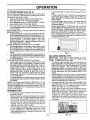
MULCHING
MOWING
TIPS
IMPORTANT:
FOR BEST PERFORMANCE,
KEEP
MOWER HOUSING FREE OF BUILT-UP GRASS AND
TRASH. CLEAN AFTER EACH USE.
•
The special mulching blade will recut the grass clippings many times and reduce them in size so that as
they tall onto the lawn they will disperse into the grass
and not be noticed. Also, the mulched grass will
biodegrade quickly to provide nutrients for the lawn.
Always mulch with your highest engine (blade) speed
as this will provide the best recutting action of the
blades.
Avoid cutting your lawn when itis wet. Wet grass tends
to form clumps and interferes with the m ulching action.
The best time to mow your lawn is the early afternoon.
At this time the grass has dried and the newly cut area
will not be exposed to the direct sun.
•
For best results, adjust the mower cutting height so that
the mower cuts off only the top one-third of the grass
blades (See Fig. 12). For extremely heavy mulching,
reduce your width of cut and mow slowly.
•
Certain types of grass and grass conditions may require that an area be mulched a second time to completely hide the clippings, When doing a second cut,
mow across or perpendicular to the first cut path.
Change your cutting pattern from week to week. Mow
north to south one week then change to east to west the
next week. This will help prevent matting and graining
of the lawn.
MOWING TIPS
Tire chains cannot be used when the mower housing is
attached to tractor.
Mower should be properly leveled for best mowing
performance, See "TO LEVEL MOWER HOUSING" in
the Service and Adjustments section of this manual.
Drive so that clippings are discharged onto the area
that has been cut. Have the cut area to the right of the
machine. This will result in a more even distribution of
clippings and more uniform cutting.
When mowing large areas, start by turning to the right
so that clippings will discharge away from shrubs,
fences, driveways, etc. After one or two rounds, mow
in the opposite direction making left hand turns until
finished (See Fig. 11).
MAX 1/3
13
FIG. 12
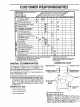
CUSTOMER
RESPONSIBILITIES
.A..TE.ANCESC.EOU'E
ASYO°COMPL E
FILL IN DATES
Check Brake Operation
If
ll_
Check Tire Pressure
if
v'
T
Check for Loose Fasteners
V'
i
harpervFteplace
Lubrication
Chart Mower Blades
T'
11_7
! If
_4
Check Battel7 Leve_Recharge
to
Clean Batter] and Terminals
Ia
If
Check Transaxle Cooling
if
Adjust Blade Belt(s) Tension
1115
Adjust Motion Ddve Belt(s) Tension
Check Engine Oil Level
Change Engine Oil
V's
If
if
1_+2.3
if
E
N
Clean Air FUter
Clean Air Screen
_l_:
G
Inspect Muffler/Spark Arrester
|
Replace Oil Filter (If equipped)
_.2
N
Replace Spark Plug
Clean Engine Cooling Fins
Replace Air Fitter Paper Cartridge
_i
If
if
Replace Fuel Filter
t
2
3
4
-
I# #'
Change more oiton when operating under a heavy load o_ in high ambient temperatures.
Sense more often when operating in dirty or dusty conditions¸
If equipped with oil I_ter, change oil every 50 hours.
Replace blades more often when mowing in sandy so_+
GENERAL
5 - 11equipped with adjustable system.
6 +Not required if equigped with maintenance-free batlery,
7 +Tighten front axle pivot bolt to 35 tt+-ths, maxlrnurn.
Do not overtigh_n.
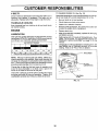
LUBRICATION
RECOMMENDATIONS
The warranty on this tractor does not cover items that have
been subjected to operator abuse or negligence.
To
receive full value from the warranty, operator must maintain
tractor as instructed in this manual.
!
CHART
(_)SPINDLE
(3_
"FRONT WHEEL
BEARING ZERK
BEARING ZERK
Some adjustments will need to be made periodically to
properly maintain your tractor.
All adjustments in the Service and Adjustments section of
this manual should be checked at least once each season.
Once a year you should replace the spark plug, clean
or replace air filter, and check blades and belts for
wear. A new spark plug and clean air filter assure
proper air-fuel mixture and help your engine run better
and last longer.
BEFORE
EACH
G'x
"_'CLUTCH
PIVOT(S)
USE
PIVOTS
Check engine oil level
Check brake operation.
(_
Check tire pressure.
Check for loose fasteners.
SAE 30 OR 10W30 MOTOR OIL
(_ GENERAL PURPOSE GREASE
(_ REFER TO CUSTOMER RESPONSIBILITIES
"ENGINE" SECTI(
IMPORTANT:
DO NOT OIL OR GREASE
THE PIVOT POIN
WHICH HAVE SPECIAL NYLON BEARINGS.
VISCOUS
LUB
CANTS WILL ATTRACT
DUST AND DIRT THAT WILL SHORT
THE LIFE OF THE SELF-LUBRICATING
BEARINGS.
IF Y
FEEL THEY MUST BE LUBRICATED,
USE ONLY A DRY, PC
14
DERED GRAPHITE
TYPE LUBRICANT
SPARINGLY.
CUSTOMER
RESPONSIBILITIES
TRACTOR
TO SHARPEN
BLADE (See Fig. 14)
Care should be taken to keep the blade balanced.
An
unbalanced blade willcause excessive vibration and eventual damage to mower and engine.
Always observe safety rules when performing any maintenance.
BRAKE OPERATION
The bladf_can be sharpened with a file or on a grinding
wheel. Do not attempt to sharpen while on the mower.
If tractor requires more than six (6) feet stopping distance
at high speed in highest gear, then brake must be adjusted.
(See "TO ADJUST BRAKE" in the Service and Adjustments section of this manual).
•
TIRES
Keep tires free of gasoline, oil, or insect control chemicals which can harm rubber.
Slide blade on to an unthreaded portion of the steel bolt
or pin and hold the bolt or pin parallel with the ground.
If blade is balanced, it should remain in a horizontal
position. If either end of the blade moves downward,
sharpen the heavy end until the blade is balanced.
Avoid stumps, stones, deep ruts, sharp objects and
other hazards that may cause tire damage.
NOTE: Do not use a nail for balancing blade. The lobes of
the center hole may appear to be centered, but are not.
Maintain proper air pressure in all tires (See "PRODUCT SPECIFICATIONS" on page 2 of this manual).
•
To check blade balance, you will need a 5/8" diameter
steel bolt, pin, or a cone balancer. (When using a cone
balancer, follow the instructions supplied with balancer).
BLADE
CARE
CENTER HOLE
For best results mower blades must be kept sharp. Replace bent or damaged blades.
BLADE
REMOVAL
(See Fig. 13)
•
Raise mower to highest position to allow access to
blades.
•
Remove hex bolt, Iockwasher and flat washer securing
blade.
•
Install new or resharpened blade with trailing edge up
towards deck as shown.
5/8" BOLT
BLADE
OR PIN
FIG. 14
Reassemble hex bolt, lock washer and flat washer in
exact order as shown.
BATTERY
Tighten bolt securely (30-35 Ft. Lbs. torque).
IMPORTANT: BLADE BOLT IS GRADE 8 HEAT TREATED.
Your tractor has a battery charging system which is sufficient for normal use. However, periodic charging of the
battery with an automotive charger will extend its life.
NOTE: We do not recommend sharpening blade - but if you
do, be sure the blade is balanced.
Keep battery and terminals clean.
Keep battery bolts tight.
BLADE
MANDREL
•
Keep small vent holes open.
•
Recharge at 6-!0 amperes for 1 hour.
TO CLEAN BATTERY AND TERMINALS
Corrosion and dirt on the battery and terminals can cause
the battery to "leak" power.
TRAILING EDGE
FLAT WASHER
•
Open battery box door.
•
Disconnect BLACK battery cable first then RED battery cable and remove battery from tractor.
LOCK WASHER
Rinse the battery with plain water and dry.
HEX BOLT
Clean terminals and battery cable ends with wire brush
until bright.
(GRADE 8)* _
Coat terminals with grease or petroleum jelly.
*A GRADE 8 HEAT TREATED BOLT CAN BE
IDENTIFIED BY SIX LINES ON THE BOLT HEAD,
Reinstall battery (See "CONNECT
Assembly section of this manual).
FIG. 13
15
BATTERY"
in the
CUSTOMER
RESPONSIBILITIES
V-BELTS
TO CHANGE ENGINE OIL (See Fig. 15)
Check V-belts for deterioration and wear after 100 hours of
operation and replace if necessary. The belts are not
adjustable. Replace belts if they begin to slip from wear.
Determine temperature range expected before oil change.
All oil must meet API service classification SF or SG.
TRANSAXLE
•
Be sure tractor is on level surface.
Oil will drairl more freely when warm.
Catch oil in a suitable container.
COOLING
Keep transaxle free from build-up of dirt and chaff which
can restrict cooling.
Remove oilfill cap/dipstick. Be careful not to allow dirt
to enter the engine when changing oil.
ENGINE
Remove drain plug.
LUBRICATION
After oil has drained completely, replace oil drain plug
and tighten securely.
Only use high quality detergent oil rated with API service
classification SForSG. Select theoil'sSAEviscositygrade
according to your expected operating temperature,
Refill engine with oil through oil fill dipstick tube. Pour
slowly. Do not overfill, For approximate capacity see
"PRODUCT SPECIFICATIONS" on page 2 of this
manual.
SAE VISCOSITY GRADES
•
-20 _
.30 o
6=
-20 o
TEMPERATURE
30 °
.i0 o
RANGe
32 = 40"
0°
ANTICIPATED
60 °
10 °
BEFORE
Use gauge on oil fill cap/dipstick for checking level. Be
sure dipstick cap is tightened securely for accurate
reading. Keep oil at "FULL" line on dipstick.
80 °
20 °
NEXT
30 °
AIR SCREEN
OIL CHANGE
NOTE: Although multi-viscosity oils (5W30, 10W30 etc.)
improve starling in cold weather, these multi-viscosity oils
will result in increased oil consumption when used above
32°F. Check your engine oil level more frequently to avoid
possible engine damage from running low on oil.
OIL FILL
CAP/DIPSTICK
Change the oil after the first two hours of operation and
every 50 hours thereafter or at least once a year if the
tractor is not used for 50 hours in one year.
Check the crankcase oil level before starting the engine
and after each eight (8) hours of operation. Tighten oil fill
cap/dipstick securely each time you check the oil level.
OIL DRAIN
PLUG
FIG. 15
16
CUSTOMER
AIR FILTER
RESPONSIBILITIES
(See Fig. 16)
CLEAN
AIR SCREEN
(See Fig. 15)
Your engine will not run properly using a dirty air filter.
Clean the foam pre-cleaner after every 25 hours of operation or every season. Service paper cartridge every 100
hours of ope ration or every season, whichever occurs first.
Air screen must be kept free of dirt and chaff to prevent
engine damage from overheating. Clean with a wire brush
or compressed air to remove dirt and stubborn dried gum
fibers.
Service air cleaner more often under dusty conditions.
Failure to clean or service air clea.ner will cause engine to
run rich and could cause spark plug fouling.
ENGINE
•
COOLING
FINS
(See Fig. 17)
Remove any dust, dirt or oil from engine cooling fins to
prevent engine damage from overheating. Air guide covers
must be removed. Remove side panels and hood (See "TO
REMOVE HOOD AND GRILL ASSEMBLY" in the Service
and Adjustments section of this manual).
Unhook clips on both sides of air cleaner and remove
cover.
TO SERVICE PRE-CLEANER
Slide foam pre-cleaner off cartridge.
Wash it in liquid detergent and water.
Squeeze it dry in a clean cloth.
Saturate it in engine oil. Wrap it in clean, absorbent
cloth and squeeze to remove excess oil.
•
If very dirty or damaged, replace pre-cleaner.
Reinstall pre-cleaner over cartridge.
•
Reinstall air cleaner cover and reattach clips to sides of
air cleaner body.
TO SERVICE CARTRIDGE
•
CLEAN THESE AREAS OF DIRT AND DEBRIS
FIG. 17
Remove knob and cartridge plate.
Carefully remove cartridge to prevent debris from entering carburetor.
MUFFLER
Clean cartridge bytapping gentlyon flat surface. Ifvery
dirty or damaged, replace cartridge.
inspect and replace corroded muffler and spark arrester (if
equipped) as it could create a fire hazard and/or damage.
Reinstall cartridge, cover plate, knob and pre-cleaner.
SPARK
Reinstall air cleaner cover and reattach clips to sides of
air cleaner body.
IMPORTANT:
PETROLEUM SOLVENTS, SUCH AS
KEROSENE,
ARE NOT TO BE USED TO CLEAN
CARTRIDGE. THEY MAY CAUSE DETERIORATION OF
THE CARTRIDGE. DO NOT OIL CARTRIDGE. DO NOT
USE PRESSUR(ZED
AIR TO CLEAN OR DRY
CARTRIDGE.
Replace spark plugs at the beginning of each mowing
season or after every 100 hours of operation, whichever
occurs first. Spark plug type and gap setting are shown in
"PRODUCT SPECIFICATIONS" on page 2 of this manual.
FOAM
PRE_LEANER
KNOB
CABTRIDee
"-"-"
PLUGS
CARTRIDGE
PLATE
3LIP
COVER
FIG. 16
17
CUSTOMER
RESPONSIBILITIES
ENGINE OIL FILTER (See Fig. 18)
IN-LINE FUEL FILTER
(See Fig. 19)
Replace the engine oil filter every season or every other oil
change if the tractor is used more than 100 hours in one
year.
The fuel filter should be replaced once each season. If fue
filter becomes clogged, obstructing fuel flow to carburetor
replacement is required.
With engine cool, remove filter and plug fuel lin_
sections.
Unscrew old filter by turning counterclockwise. Use a
suitable container to catch oil.
Apply a thin coating of new engine oil to rubber gasket
on replacement oil filter.
•
Place new fuel filter in position in fuel line with arro_
pointingtowards carburetor.
install replacement oil filter by turning clockwise until
rubber gasket contacts mounting surface, then tighten
filter an additional 1/2 to 314 turn.
•
Be sure there are no fuel line leaks and clamps ar_
properly positioned.
•
Immediately wipe up any spilled gasoline.
Fill crankcase with new oil (See "TO CHANGE ENGINE OIL" in this section of this manual). For approximate capacity see =PRODUCT SPECIFICATIONS" on
page 2 of this manual.
CLAMP.
CLAMP
Start engine andcheckfor oil leaks. Correct anyteaks
before placing engine into full operation.
FUEL
FIG, 19
CLEANING
LJL
Clean engine, battery, seat, finish, etc. of all foreigr
matter.
OIL FILTER
•
Keep finished surfaces and wheels free of all gasoline
oil, etc.
•
Protect painted surfaces with automotive type wax.
We do not recommend using a garden hose to clean you
tractor unless the electrical system, muffler, air filter an(
carburetor are covered to keep water out. Water in engim
can result in a shortened engine life.
i
FIG. 18
18
SERVICE
&
CAUTION:
•
•
•
AND ADJUSTMENTS
BEFORE PERFORMING ANY SERVICE OR ADJUSTMENTS:
Place
gearshift
lever in
neutral
position.
Depress
clutch/brake
pedal
fully(N)and
set parking brake.
Place attachment clutch in "DISENGAGED" position.
Turn ignition key "OFF" and remove key.
Make sure the blades and all moving parts have completely stopped.
Disconnect spark plug wire from spark plug and place wire where it cannot come in contact with
plug.
TRACTOR
TO REMOVE
LEVER
MOWER
(See Fig. 20)
RETAINER
CLUTCH ROD
Mower willbe easier to remove from the right side oftractor.
•
•
Place attachment clutch in "DISENGAGED" position.
Move attachment lift lever forward to lower mower to its
lowest position.
•
Roll belt off engine pulley.
•
Disconnect clutch rod from clutch lever by removing
retainer spring.
•
Disconnect anti-sway bar from chassis bracket by
removing retainer spring.
•
Disconnect suspension arms from rear deck brackets
by removing retainer springs.
•
Disconnect front links from deck by removing retainer
spdngs.
Raise lift lever to raise suspension arms. Slide mower
out from under tractor.
•
SUSPENSION
PULLEY
_IGS
(BOTH SIDES)
RETAINER
SPRING
ANTI-SWAY
IMPORTANT:
IF AN ATTACHMENT OTHER THAN THE
MOWER IS TO BE MOUNTED TO THE TRACTOR,
REMOVE THE FRONT LINKS.
TO INSTALL
MOWER
Raise attachment lift lever to its highest position.
•
Slide mower under tractor with discharge guard to right
side of tractor.
•
•
Lower lift lever to its lowest position.
Install mower in reverse order of removal instructions.
RETAINER
SPRINGS
(BOTH SIDES)
FIG. 20
(See Fig. 20)
•
BAR
19
SERVICE AND ADJUSTMENTS
TO LEVEL MOWER
HOUSING
FRONT-TO-BACK ADJUSTMENT (See Figs. 23 and 24
IMPORTANT: DECK MUST BE LEVEL SIDE-TO-SIDE. IF
THE FOLLOWING FRONT-TO-BACK ADJUSTMENT L'
NECESSARY, BE SURE TO ADJUST BOTH FRONT LINK,_
EQUALLY SO MOWER WILL STAY LEVEL SIDE-TO
SIDE.
Adjust the mower while tractor is parked on level ground or
driveway.
Make sure tires are properly inflated (See
"PROD UCT SPECIFICATIONS" on page 2 of this manual).
If tires are over or underinflated, you will not properly adjust
your mower.
To obtain the "best cutting results, the mower housin_
should be adjusted so that the front is approximately 1/8" t{
1/2" lower than the rear when the mower is in its highest
/position.
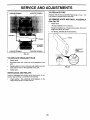
SIDE-TO-SIDE ADJUSTMENT (See Figs. 21 and 22)
Raise mower to its highest position.
At the midpoint of both sides of mower, measure height
from bottom edge of mower to ground. Distance"A" on
both sides of mower should be the same or within 1/4"
of each other.
Check adjustment on right side of tractor. Measure dis
tance "D" directly in front and behind the mandrel at botton
edge of mower housing as shown.
If adjustment is necessary, make adjustment on one
side of mower only.
•
To raise one side of mower, tighten lift link adjustment
nut on that side.
Before making any necessary adjustments, check tha
both front links are equal in length. Both links should b{
approximately 10-3/8".
•
To lower one side of mower, loosen lift link adjustment
nut on that side.
•
If links are not equal in length, adjust one link to sam_
length as other link.
To lower front of mower loosen nut "E" on both fror
links an equal number of turns.
When distance "D" is 1/8" to 1/2" lower at front thai
rear, tighten nuts "F" against trunnion on both fror
links.
NOTE: Three full turns of adjustment
mower height about 1/8"
•
nut will change
•
Recheck measurements after adjusting
BOTTOM EDGE
OF MOWER TO
BOTTOM EDGE
OF MOWER TO
GROUND
_
GROUND
•
To raise front of mower, loosen nut"F" from trunnion o=
both front links. Tighten nut "E" on both front links a=
equal number of turns.
When distance "D" is 1/8" to 1/2" lower at front that
rear, tighten nut "F" against trunnion on both front link_
Recheck side-to-side adjustment.
•
,
__
MANDREL
FIG. 21
Q
SUSPENSION
ARM
FIG. 23
BOTH FRONT LINKS MUST BE EQUAL IN LENGTH
• LIFT LINK
ADJUSTMENT
NUT
FIG. 22
rT "E"
FRONT LINKS
20
TRUNNION
FIG
24
SERVICE AND ADJUSTMENTS
TO REPLACE
(See Fig. 25)
MOWER
BLADE
DRIVE
BELT
WITH PARKING BRAKE =ENGAGED"
The mower blade drive belt may be replaced without tools.
Park the tractor on level surface. Engage parking brake.
BELT REMOVAL Remove mower from tractor (See "TO REMOVE
MOWER" in this section of this manual).
NUT "A"
Work belt off both mandrel pulleys and idler pulleys.
•
JAM NUT
Pull belt away from mower.
BELT INSTALLATION •
Install new belt in reverse order of removal.
•
•
Make sure belt is in all pulley grooves and inside all belt
guides.
Install mower in reverse order of removal instructions.
FIG. 26
MANDREL
PULLEY
IDLER
PULLEYS
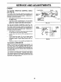
TO REPLACE
(See Fig. 27)
MOTION
DRIVE
BELT
Park the tractor on level surface. Engage parking brake.
For assistance, there is a belt installation guide decal on
bottom side of left footrest.
•
Remove mower (See "TO REMOVE MOWER" in this
section of this manual).
Remove upper belt keeper.
•
Remove belt from stationary idler and clutching idler.
Pull belt slack toward rear of tractor. Remove belt
upwards from transaxle pulley by deflecting belt keepers.
Purl belt toward front of tractor and remove downwards
from around engine pulley.
MANDREL
PULLEY
•
Install new belt by reversing above procedure.
IMPORTANT: MAKE SURE UPPER BELT KEEPER IS
POSITIONED PROPERLY BETWEEN LOCATOR TABS.
FIG. 25
TO ADJUST
BRAKE
(See Fig. 26)
ENGINE"--..
PULLEY
Your tractor is equipped with an adjustable brake system
which is mounted on the right side of the transaxle.
TABS
CLUTCHING
IDLER
If tractor requires more than six (6) feet stopping distance
at high speed in highest gear, then brake must be adjusted.
Depress clutch/brake pedal and engage parking brake.
•
KEEPER
STATIONARY
IDLER
Measure distance between brake operating arm and
nut "A" on brake rod.
If distance is other than 1-1/2", loosen jam nut and turn
nut =A" until distance becomes 1-1/2". Retighten jam
nut against nut "A".
TRANSAXLE ,__
pULLEy
"_,
Road test tractor for proper stopping distance as stated
above. Readjust if necessary. If stopping distance is
still greater than six (6) feet in highest gear, further
maintenance is necessary. Contact your nearest authorized service center/department.
FIG. 27
21
SERVICE
TRANSAXLE
SHIFTER LINKAGE
JUSTMENT (See Figs, 28 and 29)
AND ADJUSTMENTS
AND
AD-
TO REMOVE WHEEL FOR REPAIRS
(See Fig. 30)
The transaxle should be in neutral when the gear shift lever
is in the neutral (N) (lock gate) position. The adjustment is
preset at the factory; however, if adjustment is needed,
proceed as follows:
Make sure transaxle is in neutral (N).
•
Loosen two Iocknuts on tie rod.
Turn center rod until gearshift lever falls into neutral
lock gate on fender console.
•
Tighten lock,nuts securely.
Block up axle securely.
Remove axle cover, retaining ring and washers to allo_
wheel removal (rear wheel contains a square key - D(
not lose).
Repair tire and reassemble.
On rear wheels only: align grooves in rear wheel huL
and axle. Insert square key.
Replace washers and snap retaining ring securely ir
axle groove.
Replace axle cover.
WASHERS
RETAINING
RING
FIG. 28
I
AXLE COVER
LOCKNUTS
_SQUARE
KEY
(REAR WHEEL ONLY)
FIG. 30
- CENTER ROD
TO START ENGINE WITH A WEAK BATTER_
(See Fig. 31)
CAUTION: Lead-acid batteries generate explosive gases, Keep sparks, flame
and smoking materials away from batteries. Always wear eye protection
when around batteries.
TIE ROD
TRANSAXLE
If your battery is too weak to start the engine, it should b
recharged.
If "jumper cables" are used for emergenc
starting, follow this procedure:
IMPORTANT:
YOUR TRACTOR IS EQUIPPED
WITH A 1
VOLT NEGATIVE
GROUNDED
SYSTEM.
THE OTHE
VEHICLE
MUST ALSO BE A 12 VOLT
NEGATIV
GROUNDED
SYSTEM.
DO NOT USE YOUR TRACTO
BATTERY TO START OTHER VEHICLES.
FIG. 29
TO ADJUST
STEERING
WHEEL
ALIGNMENT
TO ATTACH JUMPER CABLES Connect each end of the RED cable to the POSITIV
(+) terminal of each battery, taking care not to shc
against chassis.
Connect one end of the BLACK cable to the NEGJ
TIVE (-) terminal of fully charged battery.
Connect the other end of the BLACK cable to go(
CHASSIS GROUND, away from fuel tank and batter
If steering wheel crossbars are not horizontal (left to right)
when wheels are positioned straight forward, remove steering wheel and reassemble per instructions in the Assembly
section of this manual.
FRONT WHEEL
TOE-IN/CAMBER
The front wheel toe-in and camber are not adjustable on
your tractor. If damage has occurred to affect the front
wheel toe-in or camber, contact your nearest authorizea
service center/department.
TO REMOVE CABLES, REVERSE ORDER BLACK cable first from chassis and then from the fu
charged battery.
RED cable last from both batteries.
22
SERVICE
POSITIVE TERMINAL
AND ADJUSTMENTS
TO REPLACE FUSE
NEGATIVE TERMINAL
Replace with 30 amp automotive-type plug-in fuse, The
fuse holder is located behind the dash.
TO REMOVE
(See Fig. 32)
HOOD
AND
GRILL
ASSEMBLY
Raise hood.
Unsnap headlight wire connector.
Stand in front of tractor. Grasp hood at sides, tilttoward
engine and lift off of tractor.
•
To replace, reverse above procedures.
HOOD
BATTERY
POSITIVE TERMINAL
WIRE
CONNECTOR
HEADLIGHT
NEGATIVE TERMINAL
FIG. 31
TO REPLACE
HEADLIGHT
BULB
•
Raise hood.
•
Pull bulb holder out of the hole in the backside of the
grill.
•
Replace bulb in holder and push bulb holder securely
back into the hole in the backside of the grill.
Close hood.
•
INTERLOCKS
FIG, 32
AND RELAYS
Loose or damaged wiring may cause your tractor to run
poorly, stop running, or prevent it from starting.
•
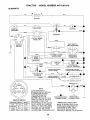
Check wiring. See electrical wiring diagram in the
Repair Parts section of this manual.
23
SERVICE AND ADJUSTMENTS
ENGINE
TO ADJUST THROTFLE
(See Fig. 33)
CONTROL
CLAMP SCREW
CABLE
The throttle control has been preset at the factory and
adjustment should not be necessary. Check adjustment as
described below before loosening cable. If adjustment is
necessary, proceed as follows:
•
CABLE
GOVERNED IDLE
SPRING
(RED OR WHITE)
With engine not running, move throttle control lever to
fast (,¢ef)position.
Check that swivel is against stop. If it is not, loosen
cable damp screw and pull cable back until swivel is
against stop. Tighten cable clamp screw securely.
TO ADJUST
CHOKE CONTROL
STOP
FIG. 33
(See Fig. 34)
The choke control has been preset at the factory and
adjustment should not be necessary. Check adjustment as
described below before loosening cable. If adjustment is
necessary, proceed as follows:
CLAMP
SCREW
CHOKE
CLOSED_
With engine not running, move choke control (located
on dash panel) to full choke (N) position.
J
Loosen knob and remove cover assembly from air
cleaner.
0
Choke should be closed. If it is not, loosen casing
clamp screw and move choke cable until choke is
completely closed. Tighten casing clamp screw securely.
o
FIG. 34
Reptace air cleaner cover assembly and tighten knob.
TO ADJUST
SWIVEL
CARBURETOR
NOTE: The carburetor on this engine is low emission. It is
equipped with an idle fuel adjusting needle with a limiter
cap, which allows some adjustment within the limits allowed by the cap. Do not attempt to remove the limiter cap.
The limiter cap cannot be removed without breaking the
adjusting needle.
The carburetor has been preset at the factory and adjustment should not be necessary. However, minor adjustment may be required to compensate fordifferences in fuel,
temperature, altitude or load. If the carburetor does need
adjustment, see engine manual.
24
r¢
STORAGE
ENGINE
Immediately prepare your tractor for storage at the end of
the season or if the tractor will not be used for 30 days or
more.
I
CAUTION: Never store the tractor with
|
gasoline in the tank inside a building
where fumes may reach an Open flame "
or spark. Allow the engine to cool
before storing in any enclosure,
FUEL SYSTEM
I
TRACTOR
IMPORTANT:
IT IS IMPORTANT
TO PREVENT
GUM
DEPOSITS
FROM FORMING
IN ESSENTIAL
FUEL
.SYSTEM PARTS SUCH AS CARBURETOR,
FUEL FILTER,
FUEL HOSE, OR TANK DURING
STORAGE.
ALSO,
EXPERIENCE
INDICATES
THAT ALCOHOL
BLENDED
FUELS (CALLED GASOHOL
OR USING ETHANOL
OR
METHANOL) CAN ATTRACT MOISTURE WHICH LEADS
TO SEPARATION
AND FORMATION
OF ACIDS DURING
STORAGE.
ACIDIC GAS CAN DAMAGE
THE FUEL
SYSTEM OF AN ENGINE WHILE IN STORAGE.
Drain the luel tank.
Remove mower from tractor for winter storage. When
mower is to be stored for a period of time, clean it thoroughly, remove all dirt, grease, leaves, etc. Store in a
clean, dry area.
•
Clean entire tractor (See =CLEANING" in the Customer
Responsibilities section of this manual).
•
Inspect and replace belts, if necessary (See belt replacement instructions in the Service and Adjustments
section of this manual).
•
Lubricate as shown in the Customer Responsibilities
section of this manual.
Start the engine and let it run until the fuel lines and
carburetor are empty.
Never use engine orcarburetorcleaner products in the
fuel tank or permanent damage may occur.
Use fresh fuel next season.
NOTE:
Fuel stabilizer is an acceptable alternative in
minimizing the formation of fuel gum deposits during storage. Add stabilizer to gasoline in fuel tank or storage
container. Always follow the mix ratio found on stabilizer
container. Run engine at least 10 minutes after adding
stabilizer to allow the stabilizer to reach the carburetor. Do
not drain the gas tank and carburetor if using fuel stabilize r.
Be sure that all nuts, bolts and screws are securely
fastened. Inspect moving parts for damage, breakage
and wear. Replace if necessary.
ENGINE
Touch up all rusted or chipped paint surfaces; sand
lightly before painting.
OIL
Drain oil (with engine warm) and replace with clean engine
oil. (See "ENGINE" in the Customer Responsibilities
section of this manual).
BATTERY
Fully charge the battery for storage.
CYLINDERS
After a period of time in storage, battery may require
recharging.
Remove spark plug(s).
To help prevent corrosion and power leakage during
long periods of storage, battery cables should be
disconnected and battery cleaned thoroughly (see =TO
CLEAN BATTERY AND TERMINALS" in the Customer Responsibilities section of this manual).
•
Pour one ounce of oil through spark plug hole(s) into
cylinder(s).
•
Turn ignitionkey to"START" pesition for a few seconds
to distribute oil.
Replace with new spark plug(s).
After cleaning, leave cables disconnected and place
cables where they cannot come in contact with battery
terminals.
OTHER
Be sure battery drain tube is securely attached.
Do not store gasoline from one season to another.
If battery is removed from tractor for storage, do not
store battery directly on concrete or damp surfaces.
•
•
Replace your gasoline can if your can stars to rust.
Rust and/or dirt in your gasoline will cause problems.
If possible, store your tractor indoors and cover it to
give protection from dust and dirt.
Cover your tractor with a suitable protective cover that
does not retain moisture. Do not use plastic. Plastic
cannot breathe which allows condensation to form and
will cause your tractor to rust,
IMPORTANT: NEVER COVER TRACTOR WHILE ENGINE
AND EXHAUST AREAS ARE STILL WARM.
25
TROUBLESHOOTING
CAUSE
PROBLEM
Will not start
Hard to start
CORRECTION
t.
Out of fuel.
2.
3.
4.
5.
6.
7.
Engine not "CHOKED"
Engine flooded.
Bad spark plug.
Dirty air filter.
Dirty fuel filter.
Water in fuel.
8.
9.
Loose or damaged wiring.
Carburetor out of adjustment.
10.
POINTS
properly.
1.
Fill fuel tank.
2.
3.
4.
5.
6.
7.
See "TO START ENGINE" in Operation section.
Wait several minutes before attempting to start.
Replace spark plug.
Clean/replace air filter.
Replace fuel filter:
Drain toe]tank and carburetor, refill tank with fresh
gasoline and replace fuel filter.
Check all wiring.
See "To Adjust Carburetor" in Service Adjustments
section.
8.
9.
10.
Engine valves out of adjustment.
Contact an authorized service center/department.
1.
2.
3.
4.
5.
6.
7.
Dirty air filter.
Bad spark plug.
Weak or dead battery.
Dirty fuel filter.
Stale or dirty fuel.
Loose or damaged wiring.
Carburetor out of adjustment.
1.
2.
3.
4.
5.
6.
7.
8.
Engine valves out of adjustment.
8.
Clean/replace air filter.
Replace spark plug.
Recharge or replace battery.
Replace fuel filter.
Drain fuel tank and refill with fresh gasoline.
Check all wiring.
See "To Adjust Carburetor" in Service Adjustments
section.
Contact an authorized service center/department.
1.
2.
3.
4.
Clutoh/brake pedal not depressed,
Attachment clutch is engaged.
Weak or dead battery.
Blown fuse.
5.
6.
7.
8.
9.
Corroded battery terminals.
Loose or damaged wiring.
Faulty ignition switch.
Faulty solenoid or starter.
Faulty operator presence switch(es).
1.
2.
3.
4,
5.
6.
7.
8.
9.
Depress clutch/brake pedal.
Disengage attachment clutch.
Recharge or replace battery.
Replace fuse.
Clean battery terminals.
Check uli wiring.
Check/replace ignition switch.
Check/replace solenoid or starter,
Contact an authorized service center/department,
Engine clicks but will not
start
1.
2.
3.
4.
Weak or dead battery.
Corroded battery terminals.
Loose or damaged widng.
Faulty solenoid or starter.
1.
2.
3.
4.
Recharge or replace battery.
Clean battery terminals.
Check allwiring.
Check/replace solenoid or sLarter.
Loss of power
f.
2.
3.
4,
5.
6.
7,
8.
9.
Cutting too much grass/too fast.
Throtlle in "CHOKE" position.
Build-up of grass, leaves and trash under mower.
Dirty air filter.
Low oil level/dirty oil.
Faulty spark plug.
Dirty fuel filter.
Stale or dirty fuel.
Water in fuel
1.
2.
3.
4.
5.
6.
7.
8.
9.
Set in =Higher Cut" posriion/reduce speed.
Adjust thratffe control.
Clean underside of mower housing.
Clean/replace air tilter.
Check oil level/change oil.
Clean and regap or change spark plug.
Replace fuel fitter.
Drain fuel tank and refill with fresh gasoline.
Drain toel tank and carburetor, retill tank with fresh
10.
11.
12.
13
14.
Spark plug wire loose.
Dirty engine air screen/fins
Dirty/clogged muffler.
Loose or damaged wiring.
Carburetor out of adjustment.
10.
11.
12.
13.
14.
15
Engine valves out of adjustment
15
Engine will not turn over
Excessive
vibration
1.
2
Worn, bent orloose blade
Bent blade mandrel.
3.
Loose/damaged
1.
2.
3
part(s).
26
gasoline and replace fuel filter.
Connect and tighten spark plug wire.
Clean engine air screen/tins.
Clean/replace muffler.
Check all wiring
See "To Adjust Carburetor" in Service Adiustments
section.
Contact an authorized service center/department.
Replace blade. Tighten blade Dolt.
Replace blade mandrel
Tighten loose part(s)
Replace damaged parts.
TROUBLESHOOTING
PROBLEM
Engine continues to run
when operator leaves seat
with attachment clutch
CAUSE
POINTS
CORRECTION
1.
Faulty operator-safety presence control system.
t.
Check widng, switches and connections.
If not
corrected, contact an authorized service center/
_leparb'nent,
1.
2.
Worn, bent or loose blade.
Mower deck not level.
1.
2.
Replace blade. Tighten blade bolt.
Level mower deck.
3.
4.
Bugdup of grass, leaves, and trash under mower.
Bent blade mandrel
5.
Clogged mower deck vent holes from buildup of
grass, leaves, and trash around mandrels.
3.
4.
5.
Clean underside of mower housing.
Replace blade mandrel.
Clean around mandrels to open vent holes.
engaged
Poorcut-uneven
Mower blades will not
rotate
Poor grass discharge
t.
Obstruction in clutch mechanism.
t.
Remove obstruction.
2.
3.
4.
Worn/damaged mower drive belt.
Frozen idler pulley.
Frozen blade mandrel.
2.
3.
4.
Replace mower drive belt.
Replace idler pulley.
Replace blade mandrel.
1.
2.
3.
4.
Engine speed too slow.
Travel speed ton fast.
Wet grass.
Mower desk not level.
1.
2.
Race thmttte control in =FAST" position,
Shift to slower speed.
3.
4.
Allow grass to dry before mowing.
Level mower deck.
5.
6.
7.
8.
Low/uneven tire air pressure.
Worn, bent or loose blade.
Buildup of grass, leaves and trash under mower.
Mower ddve belt worn.
9.
10.
1 t.
Blades impropedy installed.
{mproper blades used.
Clogged mower deck vent holes from buildup of
grass, leaves, and trash around mandrels.
5.
6.
7.
8.
9.
I 0.
11.
Check tires for proper air pressure.
Replace/sharpen blade. Tighten blade bolt.
Clean underside ct mower housing.
Replace mower ddve belt.
Reinstall blades sharp edge down.
Replace with blades listed in this manual.
Clean around mandrels to open vent holes.
Headlight(s) not working
(if so equipped)
t,
Switch is "OFF",
1.
Turn switch "ON".
2.
3.
4.
5.
Bulb(s) burned out.
Faulty light switch.
Loose or damaged widng.
Blown fuse.
2.
3.
4.
5.
Replace bulb(s).
Cheskfreplace light switch.
Check wiring and connections.
Replace fuse.
Battery witi not charge
t.
2.
3.
4.
Bad battery cell(s).
Poor cable connections.
Faulty regulator (if so equipped).
Faulty alternator.
1.
2.
3.
4.
Replacebattery.
Check/claenall connections.
Replaceregulator.
Replace alternator.
Engine "backfires"
when turning engine
"OFF"
1.
Engine throttle control not set at "SLOW"
position for 30 seconds before stopping engine.
1.
Move throttle control to "SLOW" position and allow
to idle for 30 seconds before stopping engine,
27
SERVICE NOTES
28
TRACTOR - - MODEL NUMBER AYP7167A79
SCHEMATIC
RED
BLACK
BATTERY
oq o
r
)
WHITE
O
°ED
FUSE 30 AMP.
RED
--
--
--
7 .....
'0:
BLACK
O, L
I
I
STARTER
J
i
SOLENOID
'
J
----(
G
i
L(
L .......
J
CLUTCH/ BRAKE
(PEDALUP)
WHITE
IGNITION
SWITCH
(NOT OCCUPIED)
I SEAT
- - - SWITCH
WHITE
I
BLACK
I
I
I
I
i
I
_dL-U
'
_-
(CLUTCH OFF)
j
BLACK
GROUNDING
CONNECTOR
SPARK
(OPTIONAL)
BLACK
UNIT
IGNITION
C_
FU-E-L:
I_
I
CHARP-_NG SYSllEM OUTPLrr
3 AMP DC @ 3600 RPM
FUEL SHUT-OFF
SOLENOID
ORANGE
28 VOLTS AC MIN. @ 2,600 RPM
(CHARGING SYSTEM DISCONNECTED)
BLUE
j
_J
GAP
PLUG
(2 PLUGS ON
TWIN
I
uomNG SYSTEM
_
SAMPADe_M
C')
DIODE
,I ALTERNATOR
' ,
I
j
14 VOLTS AC MIN. O 3600 RPM (LIGHTS
OFF)
HEADLIGHTS
NOTE
BROWN
YOUR TRACTOR IS
EQUIPPED WITH A SPECIAL
ALTERNATOR
SYSTEM.
THE LIGHTS ARE NOT
CONNECTED
TO THE
NON-REMOVABLE
REMOVABLE
BATTERY, BUT HAVE THEIR
CONNECTIONS
CONNECTIONS
"
OWN ELECTRICAL
SOURCE.
BECAUSE OF THIS, THE
WIRING INSULATED
CLIPS
BRIGHTNESS
OF THE LIGHTS
WILL CHANGE WITH ENGINE
NOTE: IF WIRING INSULATED
SPEED.
AT IDLE THE LIGHTS
CLIPS WERE REMOVED FOR
WILL DIM. AS THE ENGINE IS
SERVICING OF UNIT, THEY
SPEEDED
UP, THE LIGHTS
SHOULD BE REPLACED TO
WILL BECOME THEIR BRIGHTEST.
PROPERLY
SECURE YOUR WIRING.
°
IGNITION
POSITION
SWITCH
CIRCUIT
"MAKE"
OFF
G +M+L
RUN/LIGHT
B+L
RUN
B+ L
START
B + L +S
NONE
A+Y
NONE
NONE
29
o
REPAIR PARTS
TRACTOR - - MODEL NUMBER AYP7167A79
ELECTRICAL
E
I
I
I
'
t
I
i
70
I
i
43
I
26
25
q
\
\
16
J
/
/
i
52
3O
REPAIR
PARTS
TRACTOR
- - MODEL NUMBER AYP7167A79
ELECTRICAL
KEY PART
NO. NO.
1
2
3
4
6
7
8
9
10
11
12
16
19
20
21
22
24
25
26
28
29
30
31
32
33
40
41
42
43
44
45
52
55
70
144926
74760412
19091016
10040400
73220400
7697J
7603J
109596X
145211
150109
145769
153664
10090400
73350400
136850
4152J
4799J
146148
108824X
145491
121305X
140301
124211X
141226
122147X
156442
71110408
131563
145673
73640400
122822X
141940
17490508
140422
NOTE:
DESCRIPTION
Battery 12 Volt 25 Amp
Bolt Hex Hd 1/4-20unc X 3/4
Washer 9/32 X 5/8 X 16 Ga
Washer Lock Hvy Helical 1/4
Nut Fin Hex 1/4-20 Unc
Tube Plastic 46"
Tray Battery
Clamp Hose Olive
Bolt Battery Front 1/4-20 X 7.5 Zinc
Holddown Battery Front Mount
Nut Push Nylon 1/4" Battery Front
Switch Interlock Snap-In
Washer Lock 1/4
Nut Jam Hex 1/4-20 Uric
Harness Socket Light
Bulb, Light # 1156
Cable Battery 6ga 11" Red
Cable Battery 6 Ga Red w/22" wire
Fuse 30 Amp Auto Green
Cable Ground 6ga 21 "black
Switch Plunger Nc Gray
Switch Ign 4 Pos W/L P/L
Nut Ignition
Cover Sw Key
Key Ign Molded Generic
Harness Ign
Bolt Fin Hex 1/4-20uncx 1/2
Cover Terminal Red
Solenoid
Nut Keps blk H 1/4-20 Unc
Ammeter Rectangular 15 Amp
Protection Loop
Screw Thdrol 5/16-18 x 1/2 Tyt
Hamess Eng
All component dimensions given in U.S. inches
1 inch = 25.4 mm
31
REPAIR PARTS
TRACTOR - - MODEL NUMBER AYP7167A79
CHASSIS
AND ENCLOSURES
29
58
12
28
44
11_
14
37
140
26
14
34
26
32
REPAIR PARTS
TRACTOR
CHASSIS
- - MODEL
NUMBER
AYP7167A79
AND ENCLOSURES
KEY
NO.
1
2
3
4
5
6
8
9
10
11
12
13
14
15
16
17
20
23
24
25
26
28
29
30
31
33
34
35
37
38
39
44
47
51
52
53
54
55
57
58
140
PART
NO.
155051
140356
17490612
19131216
155272
155923
126471X
147633X011
72140608
155927
145660
155936
17490608
74180512
73510500
139394X418
156437
124028X
74780616
19131312
73800600
157428
146654
140002X418
137113
145244X418
145243X418
72110606
17490508
139886
139887
140675
105531X
73800400
19091416
144697
17030814
144696
74780412
150127
158418
DESCRIPTION
Chassis Wldmt. 11Ga.
Drawbar Stretch 94
Screw Thdrol. 3/8-16 x 3/4 Ty-Tt
Washer 13/32 x 3/4 x 16 Ga.
Bumper Hood/Dash
Saddle jFender Shift Flat
Clip Insulator .406 Mtg Hole
Dash Private Label w/Atom. Rect.
Bolt RdHd Sqnk. 3/8-16 Uric x 1
Panel Asm. Dash Lh
Clip Tinnerman Grile PiL
Panel Dash Rh
Screw Thdrol. 3/8-16 x 1/2 Ty-Tt
Screw Mach Trhd 5/16-18 UNC x 3/4
Nut Keps 5/16-18 UNC
Hood
Plate Mtg Battery/Fuel Tank
Bushing Snap Nyl. BIk Fuel Line
Bolt Fin Hex 3/8-16 Unc x 1 Gr. 5
Washer 13/32 x 13/16 x 12 Ga.
Nut Lock Hex w/Insert 3/8-16 UNC
Grille
Lens Grille
Fender Asm
Bracket Fender
Footrest Pnt.
Footrest Pnt.
Bolt RdHd Sht. Sqnk. 3/8-16 x 3/4
Screw Thdrol. 5/16-18 x 1/2 TYT
Bracket Asm. Pvt. Lh Mwr. Rear
Bracket Asm. Pvt. Rh Mwr. Rear
Strap Asm Fender 94
Nut Push Nylon
Nut Lock Hex W/Ins. 1/4-20
Washer 9/32 x 7/8 x 16 Ga.
Bracket, Grille, LH
Screw Lock Spider #8 x 7/8
Bracket, Grill, RH
Bolt Fin Hex 1/4-20 x .75
Air Duct Private Label
Bracket Chassis
NOTE: All component dimensions given in U.S. inches
1 inch = 25.4 mm
33
REPAIR PARTS
DRIVE
TRACTOR .. MODEL NUMBER AYP7167A79
"" " _//90
88 87
81
1
8
83 _82
66
116
4
23
22
34
26
• 118
REPAIR
PARTS
TRACTOR
- - MODEL
NUMBER
AYP7167A79
DRIVE
KEY
NO.
1
2
3
4
5
6
8
10
11
13
14
15
18
19
2t
22
24
25
26
27
28
29
30
31
32
34
35
36
37
38
39
40
41
42
47
48
49
50
51
PART
NO.
......
146682
123666X
12000028
121520X
17490512
141002
76020416
105701X
74550412
10040400
74490544
74780616
73800600
106933X
130804
73350600
106888X
19131316
76020412
145204
124236X
130807
127275X
74760512
155071
120183X
19211616
1572H
123674X
74760644
4470J
154777
19131312
127783
154604
123205X
74760624
73680600
DESCRIPTION
Transaxle, Peerless
Model No. P930-055
Spring Extension Brake
Pulley Transaxle 18"tires
Ring Retainer # 5100-62
Strap Torque Rh Pnt BIk
ScrewThdrol 5/16-18 X 3/4 Tyt
Rod Shifter
Pin Cotter
Washer Shift Plate
Bolt 1/4-28 unf Gr8 W/Patch
Washer
Bolt
Bolt Fin Hex 3/8-16 UNC x 1 Gr. 5
Nut
Knob Rd 1/2-13 PlstcThds BIk
Red, Brake
Nut
Spring Rod Brake 2 00 Zinc
Washer
Pin
Rod Brake Parking LT/YT
Cap Parking Brake Red
Bracket Mtg Transaxle
Keeper Belt Lh Lt 14 Ga
Bolt
Shaft Asm Pedal Foot 1 930
Bearing Nylon BIk 629 Id
Washer
Roll Pin
Pulley Idler Flat
Bolt
Spacer Split 395 X 59 Bzp
Keeper Belt Idler
Washer13/32X13/16X12Ga
Pulley IdlerV Groove Plastic
Bellcrank Asm
Retainer Belt Style Spring
Bolt
Nut
KEY
NO.
PART
NO. •
52
53
55
56
57
58
59
61
62
63
64
65
66
70
72
74
75
76
77
78
79
80
81
82
83
84
85
86
87
88
89
90
96
112
113
116
118
121
73680500
105710X
105709X
74760620
130801
127274X
140312
17490612
8883R
140186
71170764
10040700
154778
134683
19132012
137057
121749X
12000001
123583X
121748X
2228M
145090
145092
123782X
19171216
145643
150360
71208
19212016
12000008
139991
124346X
4497H
19091210
127285X
72110610
154474
154419
NOTE:
35
DESCRIPTION
Nut
Link Clutch 7 66
Spring Return Clutch 6 75
Bolt, Fin Hex 3/18-16 uric x 1-1/4
V-belt Ground Drive 95 25
Keeper Belt Rh Lt Pnt/zinc 16g
Keeper Belt Chassis Lh Zinc
Screw Thdrol 3/8-16x3/4 Ty-tt
Cover Pedal BIk Round
Pulley Engine
Bolt Fin Hex
Washer
Keeper Belt Engine
Guide Belt Dr Mower Rh
Washer 13/32 X 1-1/4 X 12 Ga
Spacer Axle
Washer 25/32 X 1 1/4 X 16 Ga
E Ring
Key Square 2 0 X 1845/1865
Washer 25/32 X 1 5/8 X 16ga
Key Woodruf #9 3/16 X 3/4
Arm Shift Transaxle
Shaft Asm., Cross
Spring Torsion
Washer 17/32 x 3/4 x 16 Ga.
Rod Tie
Nut, Center Lock 1/4-28
Bushing Rod
Washer
Ring, E
Console Shift 6sp N/ign Yt
Nut Self-thd Wsh-hd 1/4 Zinc
Retainer Spring 1" Zinc/Cad
Washer 9/32 X 3/4 X 10 Ga.
Strap Torque LH LT
Bolt Carriage 3/-16 x 1.25
Spacer Belicrank
Nyliner Clutching STL
All component dimensions give in U.S. inches.
1 inch = 25.4 mm.
REPAIR PARTS
TRACTOR
STEERING
- - MODEL NUMBER AYP7167A79
ASSEMBLY
•
e
"-LLL;_L-.:-
t
+-
._
,
,"_-_
51
42
54
\'\\
t
--t
\
29
. _"
43
8
36
REPAIR PARTS
TRACTOR - - MODEL NUMBER
STEERING
AYP7167A79
ASSEMBLY
KEY
NO.
1
2
3
4
5
6
7
8
9
10
11
13
15
17
18
19
20
21
22
23
25
27
29
32
36
37
38
39
40
41
42
43
44
46
47
51
54
62
63
65
66
67
68
PART
NO.
140044
137094
154920
154921
6266H
121748X
19272016
12000029
3366R
154432
10040600
154779
73901000
156546
57079
124035X
126684X
10040400
71070410
127501
154406
136874
17490612
137347
155099
152927
140045
19133808
7810H
100711L
145054
121749X
153720
121232X
6855M
73800500
74780520
156594
74780616
154780
154404
74781044
154429
DESCRIPTION
Wheel Steering Ayp/kelch BIk
Axle Asm Fr
Spindle Asm LH
Spindle Asm RH
Bearing Race Thrust Harden
Washer 25/32 X 1-5/8 X 16 Ga
Washer 27/32 X 1-1/4 X 16 Ga
Ring Klip #t5304-75
Beadng Col Strg B]k
Link Drag
Washer Lock Hvy Hlcl Spr 3/8
Bearing Axle
Nut Lock Flange 5/8-11 Unc
Shaft Asm Strg
Washer Thrust 515x 750x 033
Support Shaft
Washer Shim 1/4 X 5/8 X 062
Washer Lock Hvy Helical 1/4
Screw Hex Socket 1/4-20 X 5/8
Shaft Asm Pittman
Bracket Steering
Gear Sector 22 Teeth
Screw Thd rol 3/8-16x3/4 Ty-tt
Rod Tie
Bushing Steering
Screw TT #10-32
Cap Wheel Steer Ayp
Washer 13/32 x 2-3/8 x 8 Ga
Nut, Lock Center 2/8-24 UNF
Adapter Wheel Strg
Boot Dash P/L Steering
Washer 25/32 X 1 1/4 X 16 Ga
Extension Steering
Cap Spindle FrTop BIk
Fitting Grease
Nut Lock Hex W/Ins. 5/16-18 Unc P
Bolt Fin Hex 5/16-18 Unc P
Kit, Steering Asm Service
Bolt Fin Hex 3/8-16 x 1 Gr. 5
Spacer Axle
Bearing Arm Pittman
Bolt Fin Hex 5/8-11 UNC x 2-3/4
Brace Axle
NOTE: All component dimensions given in U.S. inches
1 inch = 25.4 mm
37
REPAIR PARTS
TRACTOR - - MODEL NUMBER AYP7167A79
SEAT ASSEMBLY
5
I
n
23
17
KEY
NO.
1
2
5
6
7
10
12
13
14
15
16
PART
NO.
140116
140551
145006
73800600
124181X
155925
121246X
121248X
72050411
134300
121250X
12
DESCRIPTION
Seat 2300/1316BIkJblk AYP/PL
Bracket Pivot Seat 8 720
Clip Push In Hinged
Nut Lock Hex W/Ins 3/8-16 Unc
Spring Seat Cprsn 2 250 BIk Zi
Pan Seat
Bracket Mounting Switch
Bushing Snap BIk Nyl 50 Id
Bolt Rdhd Sht Nk 1/4-20xl-3/8
Spacer Split 28x 96 Yel Zinc
Spring Cprsn 1 27 BIk Pnt
KEY
NO.
PART
NO.
17
21
22
23
24
25
26
27
28
123976X
153236
73800500
7478O814
19171912
127018X
10040800
17490608
150176
DESCRIPTION
Nut Lock 1/4 Lge Fig Gr 5 Zinc
Bolt Shoulder 5/16-18 Unc Blkz
Locknut 5/16-18
Bolt Fin Hex 1/2-13 X 7/8 Gr 5
Washer 17/32 X 1-3/16 X 12 Ga
Bolt Shoulder 5/16-18 X 62
Washer Lock Hvy Hlcl Spr 1/2
Screw Thdrol 3/8-16 x 1/2
Bolt 5/16-18 x 3/4
NOTE: All component dimensions given in U.S. inches
1 inch = 25,4 mm
38
REPAIR PARTS
TRACTOR
- - MODEL NUMBER
AYP7167A79
DECALS
6
2
3
4
6
10
8
10
13
11
9
KEY
NO.
1
2
3
4
5
6
7
8
9
PART
NO.
156867
143470
141579
141580
141517
143388
127520
157002
4900J
WHEELS
KEY
NO.
DESCRIPTION
10
11
12
13
14
15
16
----
Decal Oper SDL P/L Gear Dr. Eng
Decal Steering Wheel Insert
Decal Hood RH
Decal Hood LH
Decal Deck Vented Wizard Plus
Nameplate Hood Wizard Large
Decal USA White
Decal Fender Danger Eng
Decal Clutch/brake English
PART
NO.
141502
136832
158506
141583
145005
273210
150218
138311
133671
158008
DESCRIPTION
Decal Chassis 16/42 6sp Wizard
Decal V-Belt Sch
Decal Phi Side
Decal Deck Mulching Wizard Plus
Decal, Bat Dan/Poi P/L Symbols
Decal, Engine B&S
Decal Lens Wizard Plus
Decal Handle Lft Height Adjust
Pad Footrest Ribbed
Manual Owners
AND TIRES
1
2_
KEY
NO.
5,8
4,10
1
2
3
4
5
6
7
8
9
10
11
--
11
/
/
PART
NO.
59192
65139
106222X
599O4
106732X427
278H
9040H
106108X427
122082X
7152J
104757X
144334
DESCRIP_ON
Cap Valve Tire
Stem Valve
Tire F Ts 15 X 6 0 - 6 Service
Tube Front (Service Item Only)
Rim Asm 6" front White Service
Fitting Grease (Front Wheel Only)
Bearing Flange (Front Wheel Only)
Rim Asm 8" rear White Service
Tire R Ts 20 X 10-8 C Service
Tube Rear (Service Item Only)
Cap Axle BIk 1 50 X 1 00
Sealant, Tire (10 oz. Tube)
NOTE: All component dimensions given in U.S. inches
1 inch = 25.4 mm
39
REPAIR PARTS
TRACTOR
- - MODEL NUMBER AYP7167A79
ENGINE
15
14
32
31
34
33
37
39
40
41
33
29
\
OPTIONAL
EQUIPMENT
Spark Arrester
23
t
35
4O
REPAIR PARTS
TRACTOR
- - MODEL NUMBER
AYP7167A79
ENGINE
KEY
NO.
PART
NO.
1
2
3
148875
17720410
......
4
5
6
7
8
10
11
149723
122434X
122435X
138129
150176
145552
12
13
14
15
16
23
25
26
29
31
32
33
34
35
37
38
39
40
41
78
81
13280336
13200300
11050600
156123
145996
73920600
137180
151346
140527
123487X
106082X
17490512
8543R
109227X
3645J
139277
17490620
128861
NOTE:
DESCRIPTION
Control Throt Lh
Screw Hex Thd Cut 1/4-20x5/8 T
Engine (See Engine Breakdown)
Model No. 303777-1032-A1
Muffler Exhaust
Exhaust Asm. Left
Exhaust Asm. Right
Clamp Tube Double Engine
Bolt 5/16-18 x 3/4 W/Sems
Heat Shield
Washer Lock Hvy Hlcl Spr (Order From Engine
Manufacturer)
Bolt Fin Hex (Order From Engine Manufacturer)
Gasket (Order From Engine Manufacturer)
Nipple Pipe 4-1/2"
Elbow Std 90 Degree 3/8-18 Npt
Washer Lock Ext Tooth 3/8
Shield Pnt Heat Browning Grass
Control Choke
Nut Hex 3/8-24 Unf
Arrestor Spark
Tank Fuel 3 50 Rear
Cap Asm Fuel W/sym Vented
Clamp Hose Blk
Spacer Pad
Screw Hexwsh Thdrol 5/16-18 x 3/4
Line Fuel
Plug Oil Drain (Order From Engine Manufacturer)
Pad Idler
Bushing
Stem Tank Fuel
Screw Thdrol 3/8-16x1-1/4
Nut Flange 1/4-20 Starter Nut
AUcomponent dimensions given in U. S. inches
1 inch = 25.4 mm
41
REPAIR PARTS
TRACTOR
- - MODEL NUMBER AYP7167A79
LIFT
28
27
23
7
8
49
30
3
1
6
11
5
2
13
19
13
20
15
32
161718
2O
19
15
13_
32 "/
42
20
REPAIR PARTS
TRACTOR
- - MODEL NUMBER AYP7167A79
LIFT
KEY
NO.
PART
NO.
1
2
3
4
5
6
7
8
10
11
12
13
15
16
17
18
19
20
23
24
25
26
27
28
29
30
31
32
36
37
38
40
41
49
50
136973
145117
105767X
12000002
19211621
120183X
125631X
122365X
122512X
139865
139866
4939M
127218
73350800
130171
73800800
139868
3146R
110807X
19131016
2876H
76020308
126971X
73350600
138057
150233
140302
73540600
155097
123935X
17490512
19112410
123934X
145212
110452X
DESCRIPTION
Wire Asm Inner W/Plunger
Shaft Asm Lft RH
Pin Groove
E-ring Truarc #5133-62
Washer Pltd 21/32 X 1 X 21 Ga
Bearing Nylon
Grip Handle Fluted
Button Plunger Red
Spring Cprsn
Link Asm, Lift LH
Link Asm,Lift RH
Retainer Spring
Link Front
Nut Jam Hex 1/2-13 Unc
Trunnion BIk Zinc
Nut Lock W/wsh 1/2-13unc
Arm Suspension Rear
Retainer Spdng
Nut Special
Washer 13/32 X 5/8 X 16 Ga
Spring 2-1/8"
Pin Cotter 3/32 X 1/2
Rod Adj Lift Zinc 7.49 Wrk Lg
Nut Hex Jam 3/8-16 Unc
Knob Inf 3/8-16 Unc BIk W/sym
Trunnion Dp Stop Dbl Thds PLT
Bearing Pvt. Lift Spherical
Nut Crownlock 3/8-24
Pointer Height Indicator
Plug Hole BIk. 1.485/1.515 DIA.
Screw Thdrol 5/16-18 x 3/4
Washer 11/32 x 1-1/2 10 Ga
Scale Ind. Height BIk
Nut Hex Flange Lock
Nut Push Phos & Oil
NOTE: All component dimensions given in U.S. inches
1 inch = 25.4 mm
43
MOWER DECK
TRACTOR . . MODEL NUMBER AYP7167A79
\
21
\
3 24
28
1
'"
29
27
18
.
13
AA
REPAIR PARTS
TRACTOR
MOWER
KEY
NO.
- - MODEL
NUMBER
AYP7167A79
DECK
PART
NO.
1 144393
2 7214O506
3 138017
4 138440
5 4939M
6 130832
8 850857
9 10030600
10 140296
11 134149
12 129895
13 137645
14 128774
15 110485X
16 140329
17 72110610
18 72140505
19 132827
20
136888
21 73680500
22
134753
23
131267
24
105304X
25
123713X
26 110452X
27 130968
28 19111016
29 131491
30 138776
31 129963
32
153535
33
137266
34 72110614
35
133835
36
131494
37
19131316
40 73680600
41
133551
43
14O083
44 140088
45 4497H
46 137729
48
133944
49
155066
50 131340
51 69180
52 139888
53 131845X900
54 133943
KEY
NO.
DESCRIPTION
PART
NO.
DESCRIPTION
Arm Idler 42" mower LT/YT
Spacer Retainer Pm Mower
Spring Torsion Brakes 42"
Guard TUV Idler
Knob Rd
V-Belt Mower
Rod Clutch Primary 38/42
Spring Return
Arm Clutch Secondary
Washer 25/32 X 1-5/8 X 16 Ga
Ring Ktip #t5304-75
Bolt Shoulder 3/8-16 Unc 1 44
Keeper Spring 4 000
Lever Asm Clutch Primary P/L
Bushing 747 Od X 794 Lg Brass
Spring Clutch Mower
Nut Hex Jam 3/8-16 Unc
Trunnion Adj
Washer Sintered
Keeper Belt Idler
Bolt Rdhd Sqnk 3/8-16 x 2-1/4 Gr. 5
Nut Lock Flex W/Inx 3/8-16 UNC
Cover Mulching 42" Black
Screw
Washer #10
Washer Lock #10
Latch Asm Bagger
Nut Weld
Bracket Gauge Wheel LH 42" deck
Bracket Gauge Wheel RH 42" deck
Screw Thdrol 5/16-18 X 3/4 Tyt
Nut Keps 5/16-18 Unc
Bolt Carr 5/16-unc X 1/2
Bolt Shoulder
Wheel Gage
Nut Crownlock 3/8-16 Unc
Washer 12/32 x 14/16 x 12 Ga.
Bracket Extruded Gauge Wheel
Washer Felt
Washer 13/32 X 1-3/8 X 3 Ga.
Mandrel Asm Service (includes Key
Nos. 8-10, 12-15, 31 and 33)
-145411
Deck Serv (Std. Deck - Order
seperately gauge wheel components
and mulch components key nos.
101-106 and 111-121.)
NOTE: All component dimensions given in U.S. inches
1 inch = 25,4 mm
Mower Housing
Bolt Rdhd Sqnk5/16-18unc X3/4
Bracket Asm Fr Sway Bar 38/42
Bracket Asm Deck 42" sway Bar
Retainer Spring
Arm Suspension Rear
Bolt 3/8-24 X 1 1/4
Washer Lock Hvy 3/8
Washer Hard Blade Mower Vented
Blade Mulching 42"
Bearing Ball
Shaft Asm W/lower Bearing
Housing Mandrel Vented
Bearing Ball Mandrel
Stripper Mower Vented
Bolt Rdhd Sqnk 3/8-16 X 1-1/4
Bolt Rdhd Sqnk 5/16-18 X 5/8
Bolt Shoulder
Baffle Vortex42
Nut Crownlock 5/16-18 UNC
Stiffener Bracket 42" deck
Bracket Deflector Mower 42"
Cap Sleeve 80x 112 BIk Mower
Spring Torsion Deflector 2 52
Nut Push Phos & Oil
Shield Deflector Mower 42" BIk
Washer 11/32 X 5/8 X 16 Ga
Rod Hinge 42" 6 75 Wig
Screw Thdrol Hex Head Zinc Mwr
Washer Spacer Mower Vented
Pulley Mandrel 42"
Nut 9/16 Top Lock Flng
Bolt Rdhd 3/8-16uncx1-3/4 G r5
Fastner Christmas Tree
Pulley Idler Flat 3 060
Washer 13/32 x 13116 x 16 Ga
Nut Crownlock 3/8-16 UNC
Rod Pivot Wlnibs
Rod Clutch Secondary W/nibs
Guard Mandrel LH Black
Spring Retainer 1" Zinc/cad
Screw Hex Thd Cut
Washer Hardened Smaller
Roller Asm Cam Follower
Bolt Shldr 10-24 Zinc Gr 5 42"
Nut Lock #10-24 Unc
Bolt Shoulder 5/16-18 Unc Blkz
Arm Asm Pad Brake
Washer Hardened
55
56
58
59
67
68
71
72
73
74
75
76
77
78
79
80
81
82
83
84
85
92
101
102
103
104
105
106
111
112
113
114
115
116
117
118
119
121
128
132
--
45
155046
122052X
140086
141043
106932X
144200
142427
131870
127847
121748X
12000029
128903
127845
154809
127498
153701
73350600
142028
120958X
156084
72140618
73800600
136420
71161010
19061216
10071000
130758
2029J
155197
155198
17490512
73510500
72110504
137644
133957
73930600
19121414
143723
153390
19132203
130794
REPAIR PARTS
TRACTOR
PEERLESS
TRANSAXLE
-- MODEL NUMBER AYP7167A79
- MODEL NUMBER
P930-055A
103"- I
O_27
68 34
/
8
7
77
5
76
31
83
18
35
29
23
31
1
47
150
15
48
23
45
42A
79
46
43
REPAIR PARTS
TRACTOR
PEERLESS
REF PART
NO. NO.
1
2
3
4
5
6
7
8
8A
9
10
11
12
13
14
15
17
18
20
21
22
23
25
772108A
780086
770102A
776260
776219B
778139
778136
792136A
792047
784352
784355
778229
778113A
778221
778068
778260
786139
786102
792077
792078
792079
788061
792073
26
792125
27
28
29
30
31
32
33
34
35
36
37
38
39
40
41
42
792035
788040
780072
780108
780001
792001
788095
780105A
780118A
790003
790007
799021
786026
792076A
790079
792073
42A 792085A
TRANSAXLE
- MODEL
- - MODEL NUMBER AYP7167A79
NUMBER
DESCRIPTION
P930-055A
REF PART ,
NO. NO.
Cover, Transaxle
Bearing, Needle
Case, Transaxle
Shaft, Counter
Shaft and Pinion Assembly, Output
Gear, Output
Gear, Spur, 15 Teeth
Key, Shift
Key, Woodruff
Collar, Shifter
Rod and Fork Assembly, Shift
Gear, Bevel, 42 Teeth
Bevel Pinion, Input
Gear, Bevel
Gear, Bevel Pinion
Gear, Ring
Pin, Drive
Spacer. Neutral
Ball, Steel 5/16" diameter
Set Screw 3/8-16 x 3/8
Spring
Ring, Seal
Screw, Flanged Hex Head, Thread
Forming 1/4-20 x 1-1/4
Ring, Retainer
(4 Required, Package of 2)
Ring, Retainer
Ring, Retainer
Washer, Thrust
Washer, Thrust
Washer
"O" Ring
Seal, Square Cut
Bushing, Flanged
Bushing, Flanged
Disk, Brake
Plate, Brake Pad
Pad, Brake
Pin, Dowel
Washer, Fiat
Lever, Brake
Screw, Flanged Hex Head, Thread
Forming 1/4-20 x 1-1/4
Screw 1/4-20 x2-1/4
43
44
45
46
47
48
49
50
51
52
53
54
56
57
58
59
60
61
65
66
67
68
69
70
71
72
72A
76
77
792075
790025
786066
786086
774690
774691
778215
778125
778124A
778123A
778122A
778273
776230
778151
778126A
778127A
778128A
778163
780109
776135
776315A
786116A
780051
786118
788069
792165
788091
780090
786078A
79
81
792144
786081
82
83
90
103
104
150
900
786082
786123
788067B
792166
792167
510334
794603
DESCRIPTION
Locknut 5/16-24
Holder, Brake Pad
Spacer
Bracket, Brake Lever
Axle 11-5/16" long
Axle 16-1/2" long
Gear, Spur, 37 Teeth, Steel (1.,)
Gear, Spur, 35 Teeth (2.,)
Gear, Spur, 30 Teeth (3.)
Gear, Spur, 25 Teeth (4.)
Gear, Spur, 22 Teeth (5.)
Gear, Spur, 19 Teeth, Steel (6.)
Gear, Spur, 12 Teeth (1-)
Gear, Spur, 15 Teeth (2-,)
Gear, Spur, 20 Teeth (3.)
Gear, Spur, 25 Teeth (4.)
Gear, Spur, 28 Teeth (5-)
Gear, Spur, 31 Teeth (6_)
Washer, Thrust
Shaft, Input
Shaft, Brake, 4 Keyed
Plug
Washer, Thrust
Spacer
Seal, Square Cut
Plug, Threaded 9/16-18
"O" Ring
Washer, Thrust
Ring, Retaining, Inverted
(Package of 2)
Spring, Brake
Chain, Roller
(Number 41 Chain, 24 Links)
Sprocket, 9 Teeth (Reverse)
Sprocket, 18 Teeth (Reverse)
Grease, Bentonite, 32 Ounce Bottle
Screw 1/4-20 x 2
Lecknut 1/4-20
Gasket Eliminator (Loctite #515)
Replacement Transaxle
NOTE: All component dimensions given in U.S. inches
1 inch = 25.4 mm
Parts must be ordered from Tecumseh Products Co.
47
REPAIR PARTS
TRACTOR
BRIGGS
& STRATTON
ENGINE
- - MODEL NUMBER AYP7167A79
- MODEL
NUMBER
303777,
TYPE
NUMBER
1032-A1
351 •
_&265
307
232
\
0_
9
171
1023
1025
32
2;
_552
552A@
e87
614-- ..='
0_-----_ 27
27"----_oC,
-116
'kREQUIRESSPECIALTOOLS TO INSTALL
SEE REPAIRINSTRUCTIONMANUAL
48
243_<J/
819
REPAIR PARTS
TRACTOR
BRIGGS
& STRATTON
- - MODEL
ENGINE - MODEL
NUMBER
NUMBER
AYP7167A79
303777, TYPE NUMBER
1032-A1
642
_467
127
44.c
615
_1014
1977 CARBURETOR
GASKET
SET !
I 121 CARBURETOR
OVERHAUL
KIT !
387
307
823_
265
351
52
_
51
52
613
49
REPAIR PARTS
TRACTOR - - MODEL NUMBER AYP7167A79
BRIGGS
& STRATTON
ENGINE
- MODEL NUMBER
303777,
TYPE NUMBER
1032-A1
879
305
3O4
307
308.1
353A
3O5
_66
474
_334
5O
REPAIR PARTS
TRACTOR - - MODEL NUMBER AYP7167A79
BRIGGS
& STRATTON
ENGINE
- MODEL NUMBER
722_
303777, TYPE NUMBER
1032-A1
,_,67 I GAS_SeT
I
ll6A
116
1168
i
_167
@
722A
BREATHER
L VALVE
OVERHAUL
KITJ
GASKET SET
188
310
'
[
51
311
REPAIR PARTS
TRACTOR
BRIGGS
& STRATTON
KEY PART
NO. NO.
1
2
3
5
5A
6
7
8
9
10
11
12
13
15
16
18
20
22
23
24
25
26
27
28
29
32
33
34
35
40
42
45
46
50
51
52
53
54
75
78
84
87
94
95
98
104
105
108
116
807511
805107
805101
807987
807988
805193
805111
807795
805379
805751
805362
805112
805097
805048
807586
94196
807625
807638
805049
805696
807531
805016
807619
807807
807809
807811
807620
807808
807810
807812
805099
607621
807900
805395
805089
805090
805078
805092
805161
262679
807542
805409
805149
805023
805669
805006
805007
805447
91488
805054
805777
805561
807705
805586
607706
805562
805058
ENGINE
- - MODEL NUMBER AYP7167A79
- MODEL NUMBER
303777, TYPE NUMBER
KEY PART
NO. NO.
DESCRIPTION
Cylinder Assembly
Bearing, Cylinder
Seal, Oil
Head, Cylinder #1
Head, Cylinder #2
*** Washer, Cylinder Head
* Gasket, Cylinder Head
Breather Assembly
*Gasket, Breather
Screw
Tube, Breather
*Gasket, Crankcase Cover
Screw, Cylinder Head
Plug, Oil Drain
Crankshaft
Key, Timing Gear
Washers, Thrust
Cover Assembly, Crankcase
*Seal, Oil
Screw, Crankcase Cover
Flywheel, Magneto
Key, Flywheel
Piston Assembly, Standard Size
Piston Assembly, .010" Oversize
Piston Assembly, .020" Oversize
Piston Assembly, .030" Oversize
Ring Set, Piston, Standard Size
Ring Set, Piston, .010" Oversize
Ring Set, Piston, .020" Oversize
Ring Set, Piston, .030" Oversize
Lock, Piston Pin
Pin Assembly, Piston, Standard
Rod Assembly, Connecting
Screw, Connecting Rod
Valve, Exhaust
Valve, Intake
Spring, Valve
Retainer, Valve Spring
Retainer, Valve
Tappet, Valve
Gear, Cam
Manifold, Intake
*Gasket, Carburetor Mounting
"Gasket, Intake Manifold
Screw, Sems
Screw, Sems
Washer, Spring
Screw, Seres
Plug, Pipe
*Seal, Governor Shaft
** Nozzle, Carburetor
Screw, Valve Mounting
Screw, Throttle Adjusting
** Pin, Float Hinge
**Valve, Fuel Inlet
Valve, Choke
* O-Ring, Oil Pump
1032-A1
DESCRIPTION
116A 805196
* O-Ring, Crankcase Cover
116B - - " .... Gasket, Sealing (Sold in Kit)
116C
.... Gasket Plug (Sold in Kit only)
117A - - **Jet, Main (Sold in Kit and Key #147i
117B 805755****Jet, Main (High Altitude)
118 808258
** Valve Assembly, Carburetor Idle
121 808324
Carburetor Overhaul Kit
122 805770
Spacer, Carburetor
125 808255
Carburetor Assembly
127 805570
** Plug, Welch
127A 805571
** Plug, Welch
130 805572
Valve, Throttle
131 808323
Shaft, Throttle
133 807710
Float Assembly, Carburetor
137
--.... Gasket, Float Bowl
141 807711
Shaft, Choke
142 807960
** Nozzle
156 805343
Stud, Rocker Arm
161 807857
Base Assembly, Air Cleaner
166 805343
Stud, Hex, Olive
166A 805073
Stud, Oil Filter Adapter
167 805420
*** Washer, Valve Cover
171 805019
*** Nut, Nylock
187 393815
Hose, Fuel, 11" (Cut to Suit)
296004
Hose, Fuel, 23" (Cut to Suit)
188 805247
Screw, Starter Mounting
189 805449
Lock Washer
192 807623
Screw, Valve Adjustment
(Includes Jam Nut)
201 805480
Link, Governor
209 805462
Spring, Governor
209A 805453
Spring, Governed Idle
216 805439
Link, Choke
222 808195
Bracket, Governor Control
227 807528
Lever Assembly, Governor
232 805465
Spring, Governor Link
240 493629
Filter, Fuel
243 805964
Screen, Oil
254 807713
Drain, Carburetor Bowl
265 221535
Clamp, Casing
271 808145
Bracket, Choke Control
277 805018
Washer
304 807899
Housing, Blower
305 805406
Screw, Seres
307 805025
Screw, Sems
308 808309
Cover, Air Guide, Cylinder #1
308.A 608098
Cover, Air Guide, Cylinder #2
309 494990
Motor, Starting
310 94169
Bolt
311 490311
Brush Assembly
**
***
....
Included in
Included in
Included in
Carburetor
Carburetor
NOTE:
52
Gasket Set (807989)
Carburetor Overhaul Kit (808324)
Valve Overhaul Kit (807668)
Overhaul Kit (808324) and
Gasket Set (808325)
All component dimensions given in U.S. inche_
1 inch = 25.4 mm
REPAIR PARTS
TRACTOR - - MODEL NUMBER AYP7167A79
BRIGGS
& STRATTON
KEY PART
NO. NO.
324 494439
332 805028
333 492341
334 805407
337 491055
351 805169
353 92791
353A 806101
354 90576
354A 810078
356 493792
358 807989
363 19203
387 491922
423 805260
445 394018
467 491875
474 393295
501 394890
510 495878
513 398003
520 93722
523 807989
524 805011
525 807611
526 805448
527 223167
535 272490
537 805655
544 490309
552 805412
552A 805413
562 805381
572 805197
573 807663
592 805383
601 93053
613 805158
614 805417
615 805578
615A 805577
616
807596
634
805416
634A 805576
634B 805574
634C 805580
635 805529
642 807862
643 805631
657 805009
668 805402
718 805103
718A 805102
722 805483
726 807805
727 805505
729 805641
729A 280470
741 805984
783 280104
788 807685
801 394856
802 490310
ENGINE - MODEL NUMBER
303777, TYPE NUMBER
KEY PART
NO. NO.
DESCRIPTION
Screen, Rotating
Nut, Hex
Armature, Magneto
Screw, Mounting
Plug, Spark
Screw, Phillips
Washer, Lock, IntemalTooth
Washer, Lock, Internal Tooth
Nut, Hex
Nut, Hex Washer Head
Wire Assembly, Ground
Gasket Set
Puller, Flywheel
Pump, Fuel
Screw, Sems
Cartridge, Air Cleaner
Knob, AirCleaner
Stator, Alternator
Regulator, Alternator
Drive Assembly
Clutch Assembly
Terminal, Spade
Dipstick
Seal, Filler Tube
Tube, Oil Filler
Screw, Regulator Mounting
Clamp, Fuel Pipe
Element, Filter
Gasket, Air Cleaner
Armature Assembly
Bushing, Governor Shaff
Bushing, Governor Shaft
Bolt
Baffle, Breather
Back Plate Assembly, Black
Nut, Hex
Clamp, Hose
Screw, Sems
Pin, Cotter
** Retainer, Choke Shaft
** Retainer, Throttle Shaft
Fork, Governor
Washer, Governer Shaft
**Washer, Throttle
**Collar, Throttle
**Collar, Choke
Elbow, Spark Plug
Cover Assembly, Air Cleaner
Plate, Air Filter
Screw, Sems
Spacer, Rotating Screen
Dowek Crankcase
Dowel, Cylinder Head
Seal. Breather Screw
Gear, Flywheel Ring
Shield, Starter
Grommet, Ignition Cable
Clip, Wire
Gear, Timing
Gear
Bracket, Fuel Pump
Cap Assembly, Drive End
Cap Assembly, Commutator End
803
819
823
842
851
862
864
866
868
869
870
871
876
879
883
896
918
947
955
975
977
978
982
985
987
398892
805057
805317
270920
221798
807859
493880
805738
605094
805085
805086
805084
495871
805841
805024
94288
393815
807744
807714
807715
808325
805250
805030
398525
805575
1003
1004
1013
490316
805632
805581
1014
1022
1023
807797
806039
805100
807665
807546
805313
805352
805617
492932
805292
808096
805342
805341
807668
807688
807717
280275
805858
1024
1025
1026
1027
1028
1029
1030
1031
1033
1036
1037
1054
1091
1032-A1
DESCRIPTION
Housing Assembly
Screw, Sems
Screw, Mounting
O-Ring
Terminal, Ignition Cable
Bracket, Air Cleaner
Liner, Exhaust Port
Valley Cover, Air Guide
Seal, Valve Guide
Seat, Intake Valve
Seat, Exhaust Valve
Guide, Valve
Retainer Kit
Cover, Carburetor
* Gasket, Exhaust Manifold
Roll Pin
Hose, Vacuum
Solenoid
Plug And Seal, Carburetor
Bowl Assembly, Float
Carburetor Gasket Set
* Gasket, Oil Filter Adapter
Screw, Sems
Insulator, Ground Wire
** Seal, Throttle Shaft
(Included in Carburetor Gasket Set,
Part Number 807716)
Brush Spring Set
Tube, Air Inlet
** Seal, Choke Shaft
(Included in Carburetor Gasket Set,
Part Number 807716)
Deflector, Breather, A.C.
*Gasket, Valve Cover
Cover, Valve
Cover, Valve (Used on Cylinder #1)
Oil Pump Assembly
Slider, Governor
Rod, Push, Intake
Rod, Push, Exhaust
Filter, Oil
Adapter, Oil Filter
Arm, Rocker
Shaft, Rocker Arm
Support, Rocker Arm
Overhaul Kit, Valve
Breather Gasket Set
**Ball, Choke Locator
Tie, Cable
**Cap, Limiter
RPM Settings: Low Speed: 1200-1600
High Speed: 3200-3400
**
***
....
included in
Included in
Included in
Included in
Carburetor
Gasket Set (807989)
Carburetor Overhaul Kit (808324)
Valve Overhaul Kit (807668)
Carburetor Overhaul Kit (808324) and
Gasket Set (808325)
NOTE: All component dimensions given in U.S. inches
1 inch = 25.4 mm
53
HOW AND WHERE TO ORDER PARTS
1.
You can identify your product correctly by looking at its model number label which is located under the seat.
A. Name the product that needs a part, for example: tractor.
B. State the product's model number and factory number. These numbers appear on a label on the product.
2.
Listthedescriptionandpartnumberofthepartyou_,vant.
numbers.
3.
You may order from a participating Western Auto store. If you cannot do that, please order direct from:
Telephone:
ThismanuaLshowsdrawings,descdptions,
1-800-633-8434
Western Auto National Parts Center
2107 Grand Avenue
Kansas City, MO 64108
158008 12.10.96 TR
PRINTED IN U.S.A.
andpart