1
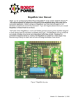
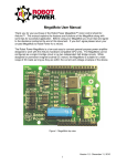
Wasp User Manual
Thank you for your purchase of the Robot Power Wasp™ motor control. This manual
explains the features and functions of the Wasp along with some tips for successful
application. Before using your Wasp you must read and agree to the disclaimer printed at the
end of this document. If you don’t agree please return your unused Wasp to Robot Power for
a refund.
The Robot Power Wasp is a low-cost, easy to connect power amplifier designed to work with
DC motors, lights, solenoids and other low-voltage DC loads. The Wasp is configured as a
single H-bridge circuit and allows bi-directional control of a single motor or other load. While
designed for permanent magnet brushed DC motors; the Wasp is suitable for a wide range of
DC loads as long as they are within the current and voltage envelope of the device.
Figure 1. Wasp top view
1. Specifications
Voltage Range
Current
PWM frequency
Over-Current and
Over-Temp
Protection
Input voltage
6V – 24V (28V absolute max)
1
10A cont. at 100% duty cycle
9A cont. at 70%
30A - 5 second peak
3.9kHz
Built-in
2.5V – 5.5V = logic high
Version 1.0 - May 26, 2011
1
levels
Size
Weight
Mounting
1.
RC standard connection
0.65” x 1.85” x 0.44”
9 gm with RC lead
1x - 4-40 or M2.5 size hole
Your actual current capacity will vary based on the type of load, the length and size of wires, power supply
capability and other factors.
2. Using the Wasp
Figure 2 shows the Wasp unit with its available connections.
Figure 2. Wasp connections
To use the Wasp, connect the RC connector to an RC signal source such as an RC receiver
or to a microcontroller unit programmed to generate servo pulses. The polarity of the
connector is shown. Generally the black/brown wire of the RC cable is oriented toward the
outside edge of the RC receiver when plugged in. Reversing the RC connection will not
damage the unit.
Connect a battery of between 6V and 28V to the battery. Up to 100% of the battery voltage
will be applied to the load. The Wasp contains an internal voltage regulator (BEC) to power
itself along with the receiver and normally does not need a receiver battery attached. Direct
solder connections of 14AWG or smaller wire are supported. An optional screw terminal block
may be soldered to either side of the PCB for easy connection of the battery and motor wires.
Polarized connectors are recommended for the battery connection to avoid reversing the
battery polarity and possibly damaging the Wasp.
A switch is recommended between the battery positive and the Wasp. The Wasp draws a
small amount of current even when the motor is not running and if left connected will drain the
battery. Auto parts stores often carry switches of appropriate current rating for the Wasp.
The motor outputs will vary between 0V and battery voltage in either polarity to provide
reversible control of the motor. Connect the wires to the motor or other load using solder
connections or the screw terminal block if installed.
To control the Wasp the RC signal is varied between neutral (off) and full forward and full
reverse at maximum stick travel. The motor LED will show this activity. The status LED will
Version 1.0 - May 26, 2011
2
glow solid when a good RC signal is detected. If the signal is lost or goes out of the legal
range the status LED will blink.
See below for instructions on using the limit switch inputs and for configuring the internal
voltage regulator and BEC for your setup.
LED Indicators
The Wasp has two LEDs used for visual indication of the state of the unit. The Status LED is
green and shows the status of the RC signal to the unit. If the Status LED is blinking either
the RC input signal is absent or out of the legal range. A solid Status LED indicates a good
RC signal and the unit is ready to receive commands.
The red/green Motor LED shows the direction and relative power output command from the
on-board CPU to the MOSFET chips. The color of the LED (red or green) indicates direction
and the brightness of the LED indicates the amount of power available to the motor. Off
indicates 0% power and full brightness indicates 100% battery voltage applied to the motor.
If the the RC signal (stick) is at neutral and the motor LED is not off or if the motor LED does
not go to full brightness in either or both directions the unit must be calibrated to store the
input signal range to the full range of the Wasp. The radio trim and ATV controls can also be
used to match the radio to the Wasp. See below for instructions on performing calibration.
5V BEC Disable
Near the motor LED is a small wire loop soldered to the Wasp circuit board. This is provided
to disable the internal 5V regulator. Above about 21V battery voltage the internal regulator will
overheat due to a limitation in its design. When operating above 21V an external 5V supply
must be used to power the Wasp’s CPU and internal circuits.
Cutting this loop disconnects the battery voltage input to the internal regulator chip. When this
loop is cut the on-board CPU and other circuits must be powered through the center wire of
the RC cable i.e. a receiver battery must be used to power the Wasp’s CPU.
If the Wasp BEC is not needed to power the receiver you can disconnect the center wire of
the RC cable either by cutting it or by pulling it from the connector shell. This allows the
internal voltage regulator to power the Wasp CPU but does not connect the 5V Wasp supply
to the receiver positive power pins. This is usually done when an external BEC or battery is
used to power the receiver or when several Wasps or other units with BEC are connected to a
single receiver. Only one BEC connection is needed to power the receiver so other units
should disconnect their 5V positive connections to avoid conflicts between the different 5V
regulators.
Version 1.0 - May 26, 2011
3
Calibration
Some receivers and radio setups have different center and endpoints than the factory
configuration shipped in a new Wasp. To match the Wasp to your actual RC range a
calibration sequence can be run. After calibration the new values are stored in the Wasp CPU
and are retained permanently.
Following is the calibration sequence:
1) Power on the Wasp either with the main battery or through the RC cable. The status
LED should be solid showing the Wasp is locked to the input signal. A motor does not
need to be connected. It is OK to power the Wasp through the RC cable with a
receiver battery and no main battery connected if desired.
2) Set the RC stick or signal source to the neutral position (center stick) with trim
centered as well.
3) Using a paperclip, tweezers or other conductive item, briefly touch the two Calibration
contacts shown in the above diagram. The status LED will begin to blink rapidly. The
motor outputs are deactivated for safety during calibration.
4) Move the stick to the extremes of travel slowly several times in each direction. The
Wasp records the range of RC signals to be used.
5) Center the stick again and touch the Calibration contacts again. This stores the
calibration values in the Wasp CPU. The values are retained and used from then on.
The motor outputs are activated as soon as the calibration values are stored.
6)
Assuming the above were done correctly the motor LED should be off and change to
full brightness as the stick is moved to the limits. That’s it!
Note, it is possible to jitter when touching the contacts and inadvertently enter then
immediately exit calibration or to exit and then enter again by touching twice quickly. No
harm is done by this just repeat the steps above until a good calibration sequence is done.
If the radio doesn’t seem to be responding properly after calibration there is no harm in
repeating the sequence until the proper range is stored in the CPU.
3. Input / Output Connections
Power Connections
Motor Outputs: The Wasp circuit is two independent half-bridge circuits mounted on a single
PCB. The two motor outputs work together to form a full H-bridge for bi-directional drive of a
motor or other load. Each motor terminal is always connected electrically to either the battery
plus or battery negative through the MOSFET power chips.
An optional 3.5mm spacing screw terminal may be soldered into the power connection pads
for easy connect and disconnect of the motor/battery leads. For permanent attachment wires
should be soldered into those positions. We recommend clearly color coding the wires and if
possible using a polarized connector to avoid incorrect battery connections.
Warning: Connecting the battery to the motor leads will quickly damage the MOSFET chips
and perhaps destroy the unit. Take care to keep the battery and motor leads separate.
Version 1.0 - May 26, 2011
4
Battery Inputs: The Wasp requires an external battery connected to the battery positive and
negative terminals. The positive terminal is marked with “++++” on the silk screen of the unit.
The polarity of the battery input must be respected. Reversing the battery connections can
damage the unit.
The Wasp does not require external filtering or voltage regulation. It may be used directly with
a 6V-28V battery or other voltage source. Connections can be made using either the optional
screw terminal or by direct solder connection.
RC Cable Connections
The Wasp commands are sent to the unit over a standard hobby RC servo lead. This is a
three-wire connector exactly like those used by servos. The Wasp expects a standard RC
servo command pulse stream as well. Many Internet resources are available which discuss
this command format and most microcontroller function libraries will contain functions suitable
for controlling the Wasp. All recent vintage RC receivers should be compatible with the Wasp.
Normally the on-board 5V regulator of the Wasp is connected to the center wire of the RC
cable. This allows the Wasp to provide power to an RC receiver or other 5V-powered device.
If the device doesn’t need that power or has its own internal 5V supply the center wire of the
RC cable should be pulled from the housing or clipped off to disconnect it from the outside
source. This allows the internal regulator to power the Wasp CPU and MOSFET circuits but
disconnects it from the outside supply.
Other Connections
Calibration Contacts: Two contacts are provided on the unit to initiate an RC signal
calibration. Shorting these contacts using a small bit of wire or other conductive material
activates the calibration function. Here at Robot Power we use fine tipped tweezers for this.
See the calibration section above for details on how and when to calibrate the Wasp.
Limit Switch Inputs: These connections are optional. The Wasp will function perfectly well
with nothing connected to these contacts. The purpose of the limit switch inputs is to stop
motion of the motor in one direction but not the other when one of the switches is closed. For
example imagine a load being driven along a track with the limit switch mounted at the end.
When the load hits the end of the track and closes the switch the Wasp cuts off the motor in
that direction. The load may still be driven in the other direction to move away from the switch
and the end of the track. As soon as the switch opens the motor may be driven in either
direction again.
The limit switch inputs are considered “open” when they are unconnected or when driven to
logic high (5V). Similarly they are considered closed i.e. activated when the input is driven
logic low (0V). The three limit switch connections as shown on the above diagram provide
connections to the two switch inputs and to a 0V connection. Thus the limit functon can use a
2-wire cable to connect a switch between the limit switch input contact and the common 0V
contact as shown in the diagram.
4. Circuit Features
The Wasp uses the Infineon BTN7960B as its power-switching element. This chip contains
two low-resistance complimentary MOSFET switching transistors along with protection and
driver circuits. Each BTN7960B contains a complete half-bridge and all needed driver circuits
including robust protection features. The device features self-protection from over
temperature, over current and over and under voltage conditions. As mentioned above the
two half-bridge chips are connected as an H-bridge.
Version 1.0 - May 26, 2011
5
The internal voltage regulator of the Wasp is a National Semi LM2940IMP-5.0 regulator. This
is a linear type regulator and generates significant heat when the difference between the
battery voltage and the 5.0V regulated output voltage is large. If the voltage regulator gets
too hot it will shut off to prevent damage. This disables the Wasp since the internal CPU uses
the output of the regulator. The Wasp has been tested up to 21V input without overloading
the regulator. For battery voltage above 21V it is recommended to use an external 5V supply
connected through the RC cable (receiver battery or BEC) and clip the 5V disable loop on the
Wasp.
5. Warnings
The following warnings should be heeded when using the Wasp to avoid failure of the device:
1. Bench type power supplies do not tolerate regenerative current i.e. current flowing
back into the power supply. Often their voltage will increase until the extra power is
dissipated. If the Wasp is operated at 24V with a power supply of this type it is
possible to exceed the maximum rating of the device and destroy the power chips.
When using a bench supply it is recommended that you operate at a lower voltage
Adding a battery in parallel with the output of the bench supply will provide a buffer
which can absorb the extra energy and avoid this type of failure.
2. Sensible driving of the load will increase the life of both the electronics and the motor.
Do not repeatedly switch instantly from full forward to full reverse. If possible reduce
the applied load voltage gradually. This allows the inductive energy in the circuit to
dissipate without the inductive voltage “kick” that often occurs on abrupt interruption of
the load current. When using a bench supply even switching from full speed to full
stop may cause an inductive kick that can damage the device if the operating voltage
is close to the upper limit.
3. Monitor the device temperatures. The power chips will protect themselves against
overloads but repeated operation until the over temperature or current protection
circuits are activated will shorten the life of the device. Add a fan to speed the cooling
and increase current capacity. During development and testing the devices should not
exceed 100C (painful to the touch) or they may exceed the operating temperature
limits during extended use.
4. In general short thick wires are your friends when using any electronic speed control.
Thin, frayed or poorly soldered wires will provide a poor connection to the load and
cause less than 100% performance and reduce reliability. Good polarized connectors
and a properly rated power switch will also help with good reliability and performance.
6. Dimensions and Mounting
Version 1.0 - May 26, 2011
6
7. Further questions
For questions not answered by this document or for application advice please feel free to
contact us. We’ll be happy to answer your questions and hopefully together we can make
your project using the Wasp a big success.
You can contact us at the following address:
Robot Power
31808 8th Ave. S.
Roy, WA 98580 USA
253-843-2504
[email protected]
Thanks again for purchasing the Wasp and best of luck with your projects.
The Robot Power Team
Disclaimer:
The Wasp is intended for educational and experimental uses. It should not be used
in applications where human life or health or significant property value depend on
its proper operation. Robot Power is not responsible for any loss or damage
incurred by the operation or failure of this unit. We make no claims as to suitability
or fitness for any application or use. The specifications listed for the unit are
accurate to the best of our knowledge but are not guaranteed in any way. The buyer
assumes all responsibility for proper use, testing, and verification of this unit in any
application. Robot Power’s liability is limited to replacement of defective DOA
units. By installing and using this unit you are agreeing to these terms. If you do
not agree you may return any unused units to Robot Power for a refund.
Version 1.0 - May 26, 2011
7