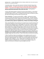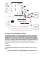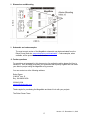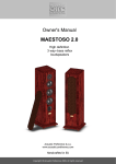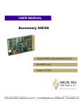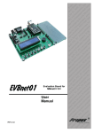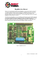
1
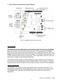
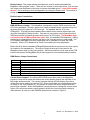
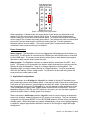
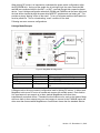
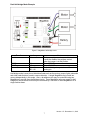
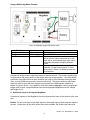
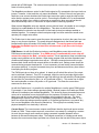
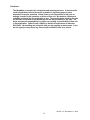
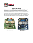
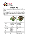
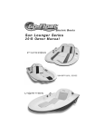
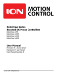
MegaMoto User Manual
Thank you for purchasing the Robot Power MegaMoto™ motor control shield for Arduino™.
This manual explains the features and functions of the MegaMoto along with some tips for
successful application. Before using your MegaMoto you must read and agree to the
disclaimer printed at the end of this document. If you don’t agree please return your unused
MegaMoto to Robot Power for a refund.
The Robot Power MegaMoto is a low-cost flexible general-purpose power amplifier designed
to work with the Arduino hardware compatible CPU units. The MegaMoto can be configured
as a single H-bridge circuit or as two independent half-bridge circuits. Designed for
permanent magnet brushed DC motors; the MegaMoto is suitable for a wide range of DC
loads as long as they are within the current and voltage envelope of the device.
Figure 1. MegaMoto top view
Version 1.5 - December 11, 2010
1
1. Specifications
Voltage Range
Current (H1
bridge)
Current (each halfbridge)
Current (ganged
half-bridge)
PWM frequency
Current Sense
Output
Digital input
voltage levels
Power Device
Size
Mounting
1.
6V – 24V (28V absolute max)
13A cont. at 100% duty cycle
12A cont. at 70%
30A - 5 second peak
Same as above
Double above
DC – 20kHz
Vc = I * 0.075
Vc = .0.75 at 10A
Vc = 2.99V at 40A
2.5V – 5.5V = logic high
<1.7V = logic low
2 ea. Infineon BTN7960B
2.1” x 2.9” x 0.5”
3x - 4-40 or M2.5 bolts. Hole
pattern matches Arduino Uno
or Duemilanove
Your actual current capacity will vary based on the type of load, the length and size of wires, power supply
capability and other factors.
2. Features
The MegaMoto uses the Infineon BTN7960B as its power-switching element. This chip
contains two low-resistance complimentary MOSFET transistors along with protection and
driver circuits. Each BTN7960B contains a complete half-bridge and all needed driver circuits
including robust protection features. The device features self-protection from over
temperature, over current and over and under voltage conditions. As mentioned above the
two half-bridge chips may be connected either as an H-bridge or as two independent halfbridges. This flexibility makes the MegaMoto suitable for driving a wide variety of DC loads.
The MegaMoto features a current sense output from each half-bridge power chip. This output
is a voltage proportional to the current flowing through the high-side transistor within the chip.
The voltage output is approximately 0.075V per Ampere of current. When jumpered for
individual current readings the A-side and B-side outputs reflect the current passing through
the MA and MB motor terminals respectively. When jumpered for combined current output the
single voltage output reflects the current flowing through both power chips. So in an H-bridge
configuration only the power chip passing current in the positive direction (high-side switch
on) will present an output; the other chip presents no voltage output. So in combined current
mode the current output is correctly proportional to the current passing through the H-bridge.
Version 1.5 - December 11, 2010
2
3. Input Output connections and Jumper Settings
Figure 2. MegaMoto connections and jumpers
LED Indicators
The MegaMoto has three LEDs used for visual indication of the state of the unit. The Enable
LED is red and when lit shows that the power chips are enabled. The green PWMA/B LEDs
show the presence of an input signal to the power chips. The brightness of the PWMA/B
LEDs will vary with the duty cycle of the input signal. Note, these LEDs reflect the state of the
inputs to the power chips not the actual output voltage. It is possible for the power chip to be
in safety shutdown while receiving an input signal. Thus it is possible for the LED to be lit but
there to be no voltage is output from the power chips.
It is possible and often prudent to code and debug the Arduino application with no battery or
motor connected to the MegaMoto but rather using the LEDs as visual indicators. The LEDs
are powered by the Arduino outputs and do not require a battery connected to the MegaMoto.
Jumper Connections
The MegaMoto uses jumpers to select which Arduino pins are used for all functions. This
allows several independently controlled MegaMoto units to be stacked on one Arduino base.
The MegaMoto also cooperates well with other shields that might have hard-wired pin
assignments.
Version 1.5 - December 11, 2010
3
Enable Jumper: This jumper selects the Arduino pin used to enable and disable the
MegaMoto under program control. There are four choices on this jumper block. One and only
one jumper must be placed on this block to choose the enable source. Logic HIGH enables
the unit. Do not attempt to drive the MegaMoto by pulsing the Enable input. This method of
driving does not work with these power chips.
Enable Jumper Connections
D13, D12, D8
5V
Enable using one of these digital pins – set HIGH to enable
The MegaMoto is always enabled (see usage notes)
PWM A/B Source Jumper: The MegaMoto is designed to use the PWM outputs from the
CPU timer peripherals. Placing a jumper onto these pin header blocks connects the input of
the power chip to the output of a CPU timer pin. The standard Arduino CPU is the
ATMega328. This chip has three hardware timers which control several digital output pins
using the AnalogWrite() library function. One and only one jumper must be placed on each
PWM source block to connect the power chip inputs to a CPU output. The MegaMoto does
not function with a PWM and Direction input. Note, the standard PWM frequency (~500hz)
provided by the AnalogWrite() function may be too low for many motors or other loads. The
CPU registers dedicated to the timer peripherals can be modified to increase the PWM
frequency. See the CPU datasheet for details on controlling the timer peripherals.
Base units other than the standard ATMega328-based Arduinos may have more timer outputs
not located on the standard pins. The output of these timers may be connected to the
MegaMoto power chips by using wire jumpers. While this method is not as clean as the PCB
internal connections, the MegaMoto still provides support for non-standard Arduino variants.
PWM Source Jumper Connections
PWMA
D6
D9
D11
PWMB
D5
D10
D3
A-side power chip
PWMA from pin D6 – Timer0 PWM0A
PWMA from pin D5 – Timer1 PWM1A
PWMA from pin D11 – Timer2 PWM2A
B-side power chip
PWMB from pin D5 – Timer0 PWM0B
PWMB from pin D10 – Timer1 PWM1B
PWMB from pin D3 – Timer2 PWM2B
Current Sense Jumpers: The Infineon BTN7960B power chips used in the MegaMoto
provide a current mirror output that reflects the current passing through the high side of the
half-bridge inside each chip. This current is passed through a 634Ω resistor to provide a
voltage that can be read by the Arduino CPU. Since the low side of the half-bridge provides
no output on the current sensor pin, it is possible to connect the sensor outputs from both
power chips in parallel. When the MegaMoto is configured as an H-bridge the current sense
output of the connected sensor outputs properly reflects the current through the bridge in
either direction. A close up of the SENSOR jumper block is shown in Figure 3.
Version 1.5 - December 11, 2010
4
Figure 3. Current sensor jumper block
When operating in H-bridge mode, the jumper shown in red above may be placed on the
header to link the current sense outputs of both chips. A second jumper chooses which
Arduino analog pin to connect to this combined signal. To monitor the individual half-bridge
current outputs, do not place the jumper shown above. Two jumpers are used to connect each
power chip’s current sense output to a different analog input pin. See the application
examples section for more details. The current sense output is optional and need not be
connected if load current monitoring is not desired.
Power Connections
Motor Outputs: The MegaMoto circuit is two independent half-bridge circuits mounted on a
single PCB. The MA output is controlled by the PWMA input and the MB output is controlled
by the PWMB input. The screw terminal and the solder pads on each side are tied together
and either or both may be used to power the load.
Battery Inputs: The MegaMoto requires an external battery connected to the BAT + and –
inputs. This battery is not connected to the Arduino supply and cannot be used to power the
Arduino through the MegaMoto. There is no voltage regulator on the MegaMoto. The
MegaMoto does not require external filtering or voltage regulation. It may be used directly
with a 6V-28V battery or other voltage source. Connections can be made using either the
screw terminal or solder pads or both.
4. Application Configurations
When connected, as an H-bridge the MegaMoto is suitable for driving DC brushed motors
both forward and reverse with variable speed. It may also be used to drive other bi-directional
loads such as Peltier junctions, electromagnets and other DC loads. Pulse-width modulation
may be applied to the inputs of the MegaMoto to vary the average voltage applied to the load.
Thus the MegaMoto supports both variable speed and direction of a single load. Since the
MegaMoto supports 100% ON and OFF signals for the inputs, you may use binary signals to
activate the power chips if variable speed is not needed.
When connected in half-bridge mode the MegaMoto may be used for driving uni-directional
loads such as lamps, heaters, solenoids or DC motors in one direction. The true half-bridge
configuration of the power MOSFETs in the BTN7960B allows for efficient driving of loads with
variable speed. Both half-bridges may operate independently or they can be ganged together
in parallel to support approximately double the current of the H-bridge or single half-bridge
configuration.
Version 1.5 - December 11, 2010
5
When driving DC motors it is important to understand the power switch configuration within
the BTN7960B chip. As long as the enable line is held logic high, the motor terminals (MA
and MB) are connected either to the BAT + or BAT - terminal through their respective power
device. In an H-bridge configuration when both PWMA and PWMB are at the same logic level
the load will be shorted through the power chip MOSFET switches and one battery rail. This
provides a strong “braking” action to the motor. To turn off all power switches the Enable line
must be pulled low. This is a freewheeling “coast” condition for the load.
Following are some common configurations:
H-bridge Mode Example
Figure 4. MegaMoto H-bridge mode
Function
Enable
PWMA
PWMB
Current Sense
Jumper
D8
D11
D3
A0 Bridged
Notes
D8 is used to enable the H-bridge
Timer2 PWM2A
Timer2 PWM2B
Both halves of the h-bridge report current on
A0
H-Bridge mode is the most common configuration used for driving DC motors. It allows each
MegaMoto to drive one DC motor in forward and reverse with variable speed. Each Arduino
Uno type base unit can support up to three stacked MegaMotos and hence three
independently controlled motors. Extended function Arduino units, such as the Arduino Mega,
with more than six timer outputs may use wire jumpers to connect to the PWMA/B inputs and
drive more than three stacked MegaMotos or use different timers than the standard Arduino.
Version 1.5 - December 11, 2010
6
Dual Half-bridge Mode Example
Figure 5. MegaMoto half-bridge mode
Function
Enable
PWMA
PWMB
Current Sense
Jumper
5V
D6
D10
MA – A3
MB – A0
Notes
Both power chips are always enabled and
cannot be disabled via program control
when the jumper is in this position
Timer0 PWM0A
Timer1 PWM1B
Each half-bridge is reported on a different
analog pin
Half-bridge mode is used for uni-directional loads such as fan motors, pumps, lights, solenoids
and other loads that don’t need to reverse direction. A single MegaMoto may control two
motors independently in this mode. Also, a brushless motor may be controlled using two
MegaMotos to provide three half-bridge circuits. Three MegaMoto units can supply six halfbridges so two brushless motors may be controlled by a full stack of three MegaMotos on a
single Arduino base.
Version 1.5 - December 11, 2010
7
Ganged Half-bridge Mode Example
Figure 6. MegaMoto ganged half-bridge mode
Function
Enable
PWMA
PWMB
Jumper
D13
D11
Jumper to D11
Current Sense
A1
Notes
Pin D13 is used to enable the MegaMoto
Timer2 PWM2A
Both the A-side and B-side chips must be
driven from the same signal source or else
there will be a momentary short from chip to
chip when they switch at slightly different
times.
Current monitoring is done on only the Bside chip. So the current read is ½ of the
total current. Either A or B-side current can
be monitored.
Ganged half-bridge mode is used for a larger uni-directional load. This mode is slightly tricky
to use because the power section of the power chips are joined together. If the chips switch
at different times there will be a short condition from chip to chip potentially destroying them.
Thus, a single PWM source must be used for both chips. This cannot be done with jumper
plugs but must be done with wire jumpers from between the PWM selection headers as
shown in Figure 6 above. It is possible to used three stacked MegaMoto units in ganged halfbridge mode to drive a large brushless motor as each ganged MegaMoto acts like a single
half-bridge circuit.
5. Additional notes on driving the MegaMoto
A number of aspects of the MegaMoto circuit are important but may not be obvious to the new
user.
Enable: The unit must have a logic high signal on the enable input to allow the power chips to
function. Unlike some of the other power drive chips available, the Enable input cannot be
Version 1.5 - December 11, 2010
8
pulsed with a PWM signal. The various internal protection circuits require a steady Enable
state to function properly.
The MegaMoto provides an option for the Enable signal as 5V connected to the input via the a
jumper. However, in that case the unit cannot be disabled. Further if the unit ever goes into
thermal or over-current shutdown the Enable input cannot be used to reset the chip and the
entire Arduino system power must be cycled. Connecting the Enable to 5V is recommended
only when the load is very unlikely to encounter an overload or when an overload should
never automatically reset i.e. user action is required before resuming operation.
When several MegaMoto units are stacked onto an Arduino base it is possible to use a single
digital pin to enable/disable all of the MegaMotos. This does not allow individual
enable/disable functions but can be used if all the loads (motors) are always enabled or
disabled together. For example a kinetic sculpture might use three motors but would never
operate just a single motor alone.
The Enable input is also used to reset the power chip protection circuits in the case of an over
temp or over current shutdown. The power chips are designed such that these faults are
latched and the chip will remain off for safety until reset. To reset the power chips after a
fault lower the Enable input for at least four microseconds (4 µS) then raise to logic
high again.
PWM Source: As with the Enable input above, each MegaMoto power chip must have a
PWM source connected to function. If no PWM source is connected the power chip will
connect its output to the Batt + rail while enabled. This is important to keep in mind during
system-reset conditions on the Arduino. When doing program load and other extended reset
conditions half-bridge connected motors will run. H-bridge connected motors will not spin
because both A-side and B-side outputs will be at the same level. Battery power should be
removed during program development. It is not necessary to have battery connected when
the system starts up. It may be connected at any time and disconnected at any time without
interrupting the Arduino program.
The PWM inputs do not have to be pulsed. A steady on-off switch-like action of the output
can be achieved if desired. Thus D3, for example, might be used as a simple digital output
pin and changing its output level between logic high and logic low will switch the B-side power
device either on (connected to Batt +) or off (connected to Batt -). This works fine for lights,
fans and solenoids or various full-power or off type loads. This frees the scarce timer
resources for other uses.
As with the Enable input, it is possible for multiple MegaMotos to use the same PWM source.
For example, if two motors always operate together, identical jumpers for Enable and PWMA/B can be installed on two stacked MegaMotos. This obviously saves pins and allows more
motors to be controlled from a single Arduino at the expense of individual control. In fact,
there is no real limit to the number of MegaMoto units controlled in this way. The three
MegaMotos per Arduino limit is only for completely independently controlled loads. If you
have five motors that always operate together or in identical groups there is no reason why
five or more MegaMoto units cannot be stacked up. This might prove unwieldy from a
physical standpoint but electrically it will work.
Current Sense: The current sensor outputs are different than the logic-level inputs such as
Enable or PWM. These outputs source a current that is converted to a voltage by a resistor.
As such they are much more sensitive to being connected in parallel between units or
between A-side and B-side power chips. The bridged connection in H-bridge mode works
because the current sense output provides zero current when the low-side of the power chip is
Version 1.5 - December 11, 2010
9
passing current. In various half-bridge modes or between stacked units, the current sensors
should not be connected in parallel.
A secondary function of the current sense output is to indicate if the device has gone into
protective shutdown. The Arduino can monitor the current sensor voltage to detect safety
shutdown. If the current sense output is giving a steady logic high a fault condition is
indicated. A short pulse on the Enable pin will reset the protection circuits and allow the
device to operate again assuming the fault condition has cleared. Over temperature
shutdown may take several seconds to clear as the device cools.
In some cases operator attention is required if the device enters shutdown i.e. some serious
or dangerous fault is indicated. In that case the power chips will remain latched off until the
power chip voltage source is cycled. The Arduino power source does not need to be cycled in
that case just the voltage source connected to the power chips.
Power connections: The power connections Batt + and Batt – are the primary voltage
source for the power chips and hence the motor outputs MA and MB. The power chips are
internally powered and no external voltage source is required to power the input or protection
circuits. The power chips are not connected to the 5V or 3.3V connections from the Arduino.
The exception is the 5V jumper on the Enable block. However, this is simply to provide a logic
high to the Enable input pins and no significant current is drawn from the Arduino 5V supply.
When multiple MegaMoto units are stacked on one Arduino base it is important that the power
connections be closely tied. Since the negative (ground) connections are common between
the Arduino and the MegaMoto there is a possibility of a “ground loop” in which the negative
rail connections have a slightly different voltage. This is commonly due a very long or thin
battery negative wire or to daisy chaining the power rails from one unit to the next in a chain.
Since the design of the MegaMoto assumes that the ground connections will be at the same
level it is important to avoid ground loops. The best practice to ensure this does not happen is
to connect the negative battery connection from each unit directly to the battery negative
terminal and not chain the negative connection from unit to unit. However, if the two or more
MegaMoto units are stacked on an Arduino it is acceptable to chain from one unit to the next
as long as a good connection is made to each unit and the wire is of sufficient size to cause
negligible voltage drop at the load current. When in doubt thicker and shorter wires are better.
Further if two different voltage sources (batteries or power supplies) are used, say one to
power the Arduino and one to power the MegaMoto, it is imperative that the connection
between the negative terminals of the voltage source be lower impedance than that between
the Arduino and the MegaMoto. This is to prevent a ground loop between the Arduino and
MegaMoto, which can destroy either unit. See Figure 7 for an illustration of this. If the
Arduino is powered by a USB connection it is not necessary to provide this negative-tonegative connection as the USB ports are protected against such faults.
Version 1.5 - December 11, 2010
10
Figure 7. MegaMoto and Arduino connected to different batteries
6. Interaction between the MegaMoto and the Arduino
The MegaMoto is designed to provide a flexible interface to the Arduino but still offer some
protection against damage to the power chips feeding into the Arduino. In the worst case a
catastrophic failure of a power chip could allow the high voltage battery voltage to appear on
the input pins. To limit the damage in this case high value resistors are inline with all Arduino
output lines. These resistors allow the low-current digital signals to pass but will drop any high
voltage present before it can effect the Arduino CPU. The exception is the current sensor
feedback analog output. This output from the power chips is not buffered and is a potential,
but extremely low probability, failure point. A proto-shield with an op-amp buffer is
recommended if maximum robustness is required along with the current feedback from the
MegaMoto.
7. Warnings
The following warnings should be heeded when using the MegaMoto to avoid failure of the
device:
1. Bench type power supplies do not tolerate regenerative current i.e. current flowing
back into the power supply. Often their voltage will increase until the extra power is
Version 1.5 - December 11, 2010
11
dissipated. If the MegaMoto is operated at 24V with a power supply of this type it is
possible to exceed the maximum rating of the device and destroy the power chips.
When using a bench supply it is recommended that you operate at a lower voltage
Adding a battery in parallel with the output of the bench supply will provide a buffer
which can absorb the extra energy and avoid this type of failure.
2. Sensible driving of the load will increase the life of both the electronics and the motor.
Do not repeatedly switch instantly from full forward to full reverse. If possible reduce
the applied load voltage gradually by reducing the PWM duty cycle over the period of a
few milliseconds. This allows the inductive energy in the circuit to dissipate without the
inductive voltage “kick” that often occurs on abrupt interruption of the load current.
When using a bench supply even switching from full speed to full stop may cause an
inductive kick that can damage the device if the operating voltage is close to the upper
limit.
3. Monitor the device temperatures. The power chips will protect themselves against
overloads but repeated operation until the over temperature or current protection
circuits are activated will shorten the life of the device. Add a fan to speed the cooling
and increase current capacity. During development and testing the devices should not
exceed 100C (painful to the touch) or they may exceed the operating temperature
limits during extended use.
4. Attempting regeneration while the battery is fully charged may lead to larger than
expected voltage rise at the battery possibly exceeding the maximum for the
MegaMoto. Many batteries have significantly increased impedance when fully
charged. This can cause a large voltage spike when attempting to flow current into the
fully charged battery. Once the battery has discharged somewhat its impedance to
reverse current should be much lower and regeneration can safely be used.
5. Disconnecting the battery from the MegaMoto while current is flowing through the load
may cause voltage spikes (inductive kick) high enough to damage the MegaMoto.
Always ensure the load current is close to zero before disconnecting the battery.
Ideally of course nothing should be connected or disconnected unless the entire
system is powered off.
6. As mentioned above, when connecting motors in half-bridge mode care must be taken
regarding the behavior of the motors when the Arduino is reset. Normally half-bridge
connected motors pass current through the high-side of the power chips. This allows
the current sensor portion of the power chip to monitor the motor current. However,
the low-side (motor lead connected to battery negative) connected motor will run when
the Arduino is reset or disconnected because the power chip turns on the high-side
power switch if there is no active input signal. Motors connected in H-bridge mode do
not run because both motor leads will be connected to battery positive during reset. In
applications where positive control of the load at all times is required, a high-side
(motor lead connected to battery plus) connected load is recommended. The current
sensor function will not work but the motor will not spin if the Arduino is reset or fails.
7. There is often confusion surrounding the term “PWM”. In common usage it can mean
either an RC servo command or a 0%-100% duty cycle square wave train. The latter
is the proper usage for the MegaMoto. The MegaMoto does not contain a CPU chip
and has no way to interpret RC servo commands such as those generated by the
servo.write() or servo.writemicroseconds() commands from the standard servo library.
The AnalogWrite() command generates the variable duty-cycle waveform that the
MegaMoto power chips will respond to.
Version 1.5 - December 11, 2010
12
8. Dimensions and Mounting
9. Schematic and code examples
The most current version of the MegaMoto schematic may be downloaded from the
Robot Power Web site. www.robotpower.com/downloads/ . Code examples, when
available, will be posted in the same location.
10. Further questions
For questions not answered by this document or for application advice please feel free to
contact us. We’ll be happy to answer your questions and hopefully together we can make
your Arduino project using the MegaMoto a big success.
You can contact us at the following address:
Robot Power
31808 8th Ave. S.
Roy, WA 98580 USA
253-843-2504
[email protected]
Thanks again for purchasing the MegaMoto and best of luck with your projects.
The Robot Power Team
Version 1.5 - December 11, 2010
13
Disclaimer:
The MegaMoto is intended for educational and experimental uses. It should not be
used in applications where human life or health or significant property value
depend on its proper operation. Robot Power is not responsible for any loss or
damage incurred by the operation or failure of this unit. We make no claims as to
suitability or fitness for any application or use. The specifications listed for the unit
are accurate to the best of our knowledge but are not guaranteed in any way. The
buyer assumes all responsibility for proper use, testing, and verification of this unit
in any application. Robot Power’s liability is limited to replacement of defective
DOA units. By installing and using this unit you are agreeing to these terms. If you
do not agree you may return any unused units to Robot Power for a refund.
Version 1.5 - December 11, 2010
14