1
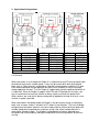
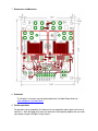
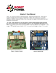
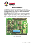
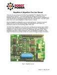
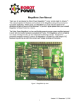
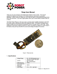
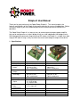
Simple-H User Manual
Thank you for your purchase of the Robot Power Simple-H. This manual explains the
features and functions of the Simple-H along with some tips for successful application. Before
using your Simple-H you must read and agree to the disclaimer printed at the end of this
document.
The Robot Power Simple-H is a low-cost easy to connect general-purpose power amplifier
that can be configured as a single H-bridge circuit or as two independent half-bridge circuits.
While designed for permanent magnet brushed DC motors; the Simple-H is suitable for a wide
range of DC loads as long as they are within the current and voltage envelope of the device.
1. Specifications
Voltage Range
Current (H1
bridge)
Current (each halfbridge)*
Current (ganged
half-bridge)*
PWM frequency
Current Sense
Output
Input voltage
levels
PA,PB,EA,EB
Size
Weight
Mounting
Fan
Without Fan
5V – 24V (28V absolute max)
20A cont. at 100% duty cycle
17A cont. at 70%
45A 5 second peak
Same as above
With Fan
Same
25A cont. at 100%
20A at 70%
45A 5 second peak
Same as above
40A cont. at 100%
35A cont. at 70%
70A 5 second peak
DC – 20kHz
Vc = I * 0.075
Vc = .0.75 at 10A
Vc = 2.99V at 40A
2.5V – 5.5V = logic high
<1.7V = logic low
48A cont. at 100%
38A cont. at 70%
70A 5 second peak
DC-20kHz
Same
2.5” x 2.25” x 0.5”
37g
4x - 4-40 or M2.5 bolts
None
2.5” x 2.25” x 0.75”
61g
Same
50mm x 10mm – 12V
Same
1.
Your actual current capacity will vary based on the type of load, the length and size of wires, power supply
capability and other factors.
2. Input Output connections and Jumper Settings
J1 Jumper Connections
The Simple-H ships with two jumpers used to select the enable and current sense options of
the unit. By default these are installed on EA and CA for combined enable and current sense
operation (see below). If separate enable and/or current sense is desired the jumper should
be moved to the EAB or CAB position. The jumpers should always be mounted in one
position or the other. If they are not mounted the B-side power chip will not be enabled and/or
the B-side current reading will not be available.
The jumpers should always be placed across the rows of pins in line with the label on the
PCB.
EA
EAB
CA
CAB
EA input on CN1 enables BOTH power chips
EA enables the M1 chip and EB enables the M2 chip
CA output on CN1 reflects BOTH power chips (combined output)
CA output reflects the M1 chip current and CB reflects M2 chip current
CN1 is the primary control input/output connector for the unit. There is no electrical isolation
between the power chips and the input connector so care should be taken when connecting to
sensitive equipment. The Simple-H ships with either an 8-position screw terminal block in this
position or various pin headers for specific user connector applications. The Screw terminal
may be removed if desired and replaced with a 0.1” spacing pin header of the users’ choice.
CN1 Input / Output Connections
PA
PB
EA
CA
EB
CB
–
+
PWM-A input to M1 power chip may be pulse-width modulated or DC
PWM-B input to M2 power chip
Enable A & B when EA jumper is on or Enable A-side only when EAB jumper is on
A-side (M1) current sense output if CAB is mounted or the combined current sense
if CA is mounted.
Enable-B only used if EAB is mounted
Current sense B only used if CAB is mounted
Battery negative (Ground) – Connect to signal source ground for voltage reference
Battery positive - Output to external voltage regulator – Do not connect to an
external battery or voltage source!
3. Application Configurations
J1 EA
J1 CA
PA
PB
EA
CA
EB
CB
On
On
PWM Fwd
PWM Rev
Enable
Current Sense
N/C
N/C
J1 EAB
J1 CAB
PA
PB
EA
CA
EB
CB
On
On
PWM Motor 1
PWM Motor 2
Enable Mot 1
Current Mot 1
Enable Mot 2
Current Mot 2
J1 EA
J1 CAB
PA
PB
EA
CA
EB
CB
On
On
PWM M1
Tie to PA
Enable
Current A*
N/C
N/C
* The current reading will only be for the current passing through the M1 power chip, which is
½ of the total.
When connected, as an H-bridge the Simple-H is suitable for driving DC brushed motors both
forward and reverse with variable speed. It may also be used to drive other bi-directional
loads such as Peltier junctions, bi-directional solenoids, electromagnets and other DC loads.
Pulse-width modulation may be applied to the inputs of the Simple-H to vary the average
voltage applied to the load. Thus the Simple-H supports both variable speed and direction of
a single load. Since the Simple-H supports 100% ON and OFF periods for the inputs, you
may use mechanical or electrical switches or binary signals to activate the power chips.
When switches are used the full battery voltage will be applied to the load at all times so no
variation in speed is possible.
When connected in half-bridge mode the Simple-H may be used for driving uni-directional
loads such as lamps, heaters, solenoids or DC motors in one direction. The true half-bridge
configuration of the power elements in the drive chips allow for efficient driving of loads with
variable speed when compared to a single low- or high-side switch configuration with a
recirculation (Schottky) diode. The Simple-H half-bridge drive features improved heat
dissipation and current capacity along with temperature and current protection and current
sensing.
Both half-bridges may operate independently or they can be ganged together in parallel to
support approximately double the current of the H-bridge or single half-bridge configuration.
When driving DC motors it is important to understand the power switch configuration within
the BTS7960B chip. As long as the enable line (EA or EB) is held logic high, the motor
terminal (M1 or M2) is connected either to the B+ or B- terminal through the device. In an Hbridge configuration when both PA and PB are at the same logic level the load will be shorted
through both the top switches and the positive battery rail or the bottom switches and the
negative rail. This provides a strong “braking” action to the motor. To turn off both power
switches the Enable (EA and/or EB) line must be pulled low. This is a freewheeling “coast”
condition for the load.
4. Features
The Simple-H uses the Infineon BTS7960B as its power-switching element. This chip
contains two low-resistance complimentary MOSFET switching elements along with protection
and driver circuits. Each BTS7960B thus contains a complete half-bridge and all needed
driver circuits including robust protection features. The device features self-protection from
over temperature, over current and over and under voltage conditions. As mentioned above
the two half-bridge chips may be connected either as an H-bridge or as two independent halfbridges. This flexibility makes the Simple-H suitable for driving a wide variety of DC loads.
The Simple-H features a current sense output from each half-bridge power chip. This output
is a voltage proportional to the current flowing through the chip. The voltage output is
approximately 0.075V per Ampere of current. When jumpered for individual current readings
the CA and CB outputs reflect the current passing through the M1 and M2 motor terminals
respectively. When jumpered for combined current output the CA output reflects the
combined current flowing through both power chips. However, the current reading may not be
negative so in an H-bridge configuration only the one power chip passing current in the
positive direction (high-side switch on) will present an output; the other chip presents no
voltage output. So in combined current mode the current output is correctly proportional to the
current passing through the H-bridge.
5. Driving the Simple-H
IMPORTANT you cannot simply connect the battery voltage to the EA, EB, PA and PB
inputs through a switch. The maximum voltage level on these inputs is 6V.
Connecting them directly to the battery voltage will damage the unit.
The fan and the +/- positions on the screw terminal block are directly connected to the
B+ and B- battery terminals. These are provided for convenience connections to the
main battery. DO NOT ATTACH AN EXTERNAL BATTERY OR VOLTAGE SOURCE TO
THESE. The Simple-H is completely self-powered and the main battery connection is
all that is needed.
The EA/EB and PA/PB inputs are inputs which control the output of the power chips in the
Simple-H. The Simple-H inputs must be driven by 3V-5V logic-level signals. These voltage
levels are compatible with nearly all microprocessors and controllers. Note, however that the
Simple-H is not optically isolated from the command inputs so in the unlikely event of a total
power chip failure it is possible that the full battery voltage could be applied to the command
input pins. Protection devices are installed to limit the damage but users are advised to take
precautions to protect the device controlling the Simple-H.
It is recommended that you drive the load using the sign-magnitude method for H-bridge
applications. This method allows the excess current to recirculate in the motor windings and
reduces current feeding back into the power supply.
If locked-antiphase drive is desired be aware that the power dissipation will increase
especially in the main filter capacitor. This should be monitored carefully by measuring the
temperature of the filter capacitor to make sure it is not getting hot when driving the load. The
PWM frequency should be as high as possible when driving with this method to reduce the
ripple current experienced by the load and the Simple-H.
If regenerative braking of an inductive load such as a motor is desired it can be accomplished
as follows: when slowing or reversing direction supply a low duty cycle drive to the load until
the load has stopped or has reached a low RPM, then apply a brake or coast stop signal to
the unit. The low average applied voltage of the low duty-cycle drive will allow the inductance
of the load to boost the voltage at the battery terminals above the supply voltage and flow
current back into the battery. Unfortunately the current sensors will not read properly during
regeneration so the regeneration current level cannot be measured. Do not attempt
regeneration with a bench power supply only with a battery.
6. Warnings
The following warnings should be heeded when using the Simple-H to avoid failure of the
device:
1. Bench type power supplies do not tolerate regenerative current i.e. current flowing
back into the power supply. Often their voltage will increase until the extra power is
dissipated. If the Simple-H is operated at 24V with a power supply of this type it is
possible to exceed the 28V maximum rating of the device and destroy the power chips.
When using a bench supply it is recommended that you operate at a lower voltage
Adding a battery in parallel with the output of the bench supply will provide a buffer
which can absorb the extra energy and avoid this type of failure.
2. Sensible driving of the load will increase the life of both the electronics and the motor.
Do not repeatedly switch instantly from full forward to full reverse. If possible reduce
the applied load voltage gradually by reducing the PWM duty cycle over the period of a
few milliseconds. This allows the inductive energy in the circuit to dissipate without the
inductive voltage “kick” that often occurs on abrupt interruption of the load current.
When using a bench supply even switching from full speed to full stop may cause an
inductive kick that can damage the device if the operating voltage is close to the upper
limit.
3. Monitor the device temperatures. The power chips will protect themselves against
overloads but repeated operation until the over temperature circuits are activated will
shorten the life of the device. Add a fan to speed the cooling and increase current
capacity.
4. When cooling the device a fan is the recommended method. The heatsink tabs are
electrically connected to the motor outputs so the heatsinks must be isolated from
each other (except in the ganged half-bridge mode). Fan cooling is effective even in
an enclosed box so it may not be necessary to introduce outside air for effective
cooling.
5. If the Simple-H is coated with conformal PCB coating products please ensure the
heatsinks are masked and left free of coating.
6. Monitor the terminal connectors especially if fork type terminals are used. It is possible
for them to twist and come in contact with the filter capacitor. If the filter cap is too
close to the B+ and B- terminals it may be gently pushed back toward the heatsinks. It
should have some clearance and not press tightly against the heatsinks because
vibration may wear through the plastic coating and cause a short circuit. Tighten all
screws securely and use thread locker if needed to ensure the terminal screws remain
tight. Note, if the M1 and M2 connectors do twist and contact the heatsink that is not a
problem since they are electrically connected anyway.
7. Attempting regeneration while the battery is fully charged may lead to larger than
expected voltage rise at the battery possibly exceeding the maximum for the Simple-H.
Many batteries have significantly increased impedance when fully charged. This can
cause a large voltage spike when attempting to flow current into the fully charged
battery. Once the battery has discharged some its impedance to reverse current
should be much lower and regeneration can safely be used.
7. Dimensions and Mounting
8. Schematic
The Simple-H schematic may be downloaded from the Robot Power Web site.
www.robotpower.com/downloads/
9. Further questions
For questions not answered by this document or for application advice please feel free to
contact us. We’ll be happy to answer your questions and hopefully together we can make
your project using the Simple-H a big success.
You can contact us at the following address:
Robot Power
31808 8th Ave. S.
Roy, WA 98580 USA
253-843-2504
[email protected]
Thanks again for purchasing the Simple-H and best of luck with your projects.
The Robot Power Team
Disclaimer: The Simple-H is intended for educational and experimental uses. It
should not be used in applications where human life or health or significant
property value depend on its proper operation. Robot Power is not responsible for
any loss or damage incurred by the operation or failure of this unit. We make no
claims as to suitability or fitness for any application or use. The specifications
listed for the unit are accurate to the best of our knowledge and testing but are not
guaranteed in any way. The buyer assumes all responsibility for proper use,
testing, and verification of this unit in any application. Robot Power’s liability is
limited to replacement of defective DOA units. By installing and using this unit you
are agreeing to these terms. If you do not agree you may return any unused units to
Robot Power for a refund.