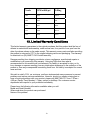
1
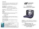
MISTIFYER ANTI-DRIP SYSTEMTM Operating Instructions 120v MISTIFYER ANTI-DRIP SYSTEM SystemTM P/N 100061 Super Fine 56 nozzles P/N 100071 Fine 35 nozzles P/N 100088 Heavy 25 nozzles 230v MISTIFYER ANTI-DRIP SYSTEM SystemTM P/N 100063 Super Fine 56 nozzles P/N 100079 Fine 35 nozzles P/N 100093 Heavy 25 nozzles Thank you for purchasing this MISTIFYER ANTI-DRIP SYSTEMTM As you will notice from the table of contents, the manual for your new pump is quite extensive. To guarantee perfect and successful work with this machine, please take time to read the manual carefully. Do not operate before removing wood in vented oil plug! And finally, we believe you will enjoy many years of dependable, trouble free service if you properly install and maintain this powerful piece of machinery called the MISTIFYER ANTI-DRIP SYSTEMTM CITC 2100 196th St. S.W., Ste. 138 Lynnwood, WA 98036 (888) 786-CITC www.citcfx.com 1 Contents 1. Equipment Supplied 3 2. Accessories and Parts 3 3. Safety information 4 4. Grounding Instructions 4 5. Receiving and Unpacking 5 5.1 5.2 Checking for Damage in Shipping Checking Inventory of Parts 6. Pump Start-up Procedure 6.1 6.2 Oil Reservoir Plug Removal Pump Preparation 7. Hooking up the Pump 7.1 7.2 7.3 Installation of Pump Water Supply Water Filter Installation 8. Mist Line Layout Strategies 8.1 8.2 8.3 8.4 Light, Medium or Heavy Haze Indoor Fog Curtains Raise Humidity to Keep Dust Down Project Images and Lasers 9. Mist Line Assembly 9.1 9.2 9.3 9.4 9.5 9.6 Tubing Connection Pre-Installation System Test Pressure Regulation Checking for Leaks Adjusting the Fog Pattern Mounting the Mist Line 10. Maintenance procedures 10.1 10.2 10.3 10.4 System Pressure Changing the Pump Oil External Water Filter Inspection Drive Belt Inspection 11. Troubleshooting 11.1 11.2 11.3 11.4 11.5 11.6 11.7 Low Pressure Water continues to run through pump after pump is turned off Pump stops running Oil leaking around pump Pulsation Water leakage from under manifold Water in crankcase (looks like bubbles, or milky color) 12. Technical Data 13 13. Limited Warranty Conditions 14 6 6 7 8 11 12 2 1. Equipment Supplied 120v MISTIFYER ANTI-DRIP SYSTEM SystemTM P/N 100061 Super Fine 56 nozzles P/N 100071 Fine 35 nozzles P/N 100088 Heavy 25 nozzles 230v MISTIFYER ANTI-DRIP SYSTEM SystemTM P/N 100063 Super Fine 56 nozzles P/N 100079 Fine 35 nozzles P/N 100093 Heavy 25 nozzles (Please see section 5.2 for a complete checklist.) 2. Accessories and Parts 100068 250042 600720 600721 600722 600723 600724 600725 600726 600727 600728 600729 600730 600731 600732 600733 600734 600735 600736 600737 600738 600739 600740 600741 600742 600743 600744 600746 600747 600748 600749 600751 600752 600755 600756 600758 600759 600760 600761 600762 600763 600764 600765 600766 600768 600770 600771 600782 10 Nozzle Anti-Drip Pump Kit Universal DMX Relay 3-pin XLR, Heavy Duty Filter Housing with Bracket Kit 5-Micron Sediment Filter Cartridge 1.5" Automatic Drain Valve .008 Nozzle with 10/24 Thread (fine) .012 Nozzle with 10/24 Thread (heavy) Push Connector Quick Device - Tee Only (included) Push Connector Quick Device - Tee with Fine Nozzles (.008) Push Connector Quick Device - Tee with Heavy Nozzles (.012) Nylon Tubing 3/8" OD (1cm) (price per foot) Nylon Tubing 3/8" OD (1cm) (28" length, included (71.1cm)) Nylon Tubing 3/8" OD (1cm) (50' roll (15.2m)) Nylon Tubing 3/8" OD (1cm) (100' roll (30.5m)) Tubing Cutter Push Connector Quick Device - Brass Hose Adapter Push Connector Quick Device - End Plug (included) Push Connector Quick Device - 3/8" MIP Adapter (included) Push Connector Quick Device - Brass 90 Elbow (included) Push Connector Quick Device - Three-way Tee (included) Push Connector Quick Device - 4-Way Cross ½" Brass Nozzle Extension 1½" Brass Nozzle Extension 8 oz. Bottle of Nozzle Cleaner (0.24 liter) 1 Gallon Bottle of Nozzle Cleaner (3.8 liter) Anti-Drip Extension with .008 (fine nozzle) Anti-Drip Extension with .012 (heavy nozzle)(included) 3/8" (1cm) Steel Clamp Vinyl-Coated Tie Wraps (included) 10/24 Nozzle Plug .008 Nozzle O-Ring (Red) .012 Nozzle O-Ring (Black) ¼" HP Solenoid Valve 120 N.O. with Setup Push Connector, coupling Push-Connector Quick Device Brass Union 2000 PSI Pressure Gauge Labor Pump Assembly 10' Low-Pressure Tubing (3m) 5' Low-Pressure Tubing with Hose Adapter (1.5m) 3' Low-Pressure Tubing for Filter to Pump (90cm) 2' Low-Pressure Tubing for Drain to Bucket (60cm) 1 Gallon Bottle (Drain Container) Oil Plug with Warning Sign Jungle Mist Instruction Booklet and Price Sheet Set of 4 Wheels 2X Push-Connector Auto Drain-down (anti-freeze) Pump Water Seal Kit 6 Valve Rebuild Kit Push-con Union 3 3. Safety Information WARNING: Read through the entire instructions before attempting installation. • • • Risk of electrical shock - This pump is supplied with a grounding conductor. To reduce risk of electrical shock, connect only to a properly grounded, grounding type receptacle. Have a qualified electrician wire the pump to a dedicated, fused circuit. Install pump on a flat, level, solid foundation. This pump is non-submersible. CAUTIONS: • **Before operation remove wood plug from oil breather plug. Failure to do this will void the warranty. Pump must be able to breathe. (See section 6.1 for more details.)** • • • • • Pump warranty is voided by failure to use factory- supplied filter on water supply! Water filter is installed on water INLET line! (See section 7.3 for more details.) To reduce risk of electric shock, disconnect power before servicing this pump. Maximum design pressure is 800 PSI (55 bar) continuous. Under no circumstances should the pressure be allowed to go higher than 1000 PSI (69 bar). This pump has been evaluated for use with water only. Do not use with any other liquids. To reduce risk of electric shock, install with all electrical components well-grounded and dry. 4. Grounding Instructions 4.1 The pump should have a dedicated circuit 4.2 The pump MUST BE GROUNDED! In the event of a malfunction or breakdown, grounding will reduce the risk of electric shock by providing a path of least resistance for the electric current. Install electrical hookup in accordance with all local codes and ordinances. Warning: Improper connection of the equipment-grounding conductor can result in a risk of electric shock. Check with a qualified electrician if you are in doubt whether the pump is properly grounded. Never use a two-prong outlet or cut off the third prong on the plug! 4 5. Receiving and Unpacking 5.1 CHECKING FOR DAMAGE IN SHIPPING • 5.2 Carefully examine contents for signs of damage in shipping. Immediately notify the carrier if damage is detected that was not visible upon receipt of shipment. CHECKING INVENTORY OF PARTS MISTIFYER ANTI-DRIP SYSTEM SystemTM *Number of nozzles and connectors according to unit ordered. i.e 35, 56 etc. CITC ITEM # QTY. 600791 1 600720 600721 600725 600729 600730 600732 600734 1 1 * * 1 1 * 600736 * 600737 * PART DESCRIPTION MISTIFYER ANTI-DRIP SYSTEM – 1 gpm 1hp 120VAC Pump Only (230VAC version P/N 600792) Filter Housing 5-Micron Sediment Filter Cartridge Push Connector Quick Device – Tee Only Nylon Tubing 3/8” OD (28” Length) Nylon Tubing 3/8” OD (50’ Roll) Tubing Cutter Push Connector Quick Device – End Plug Push Connector Quick Device – Brass 90 Elbow Push Connector Quick Device – Three Way Tee 600746 75 3/8” Steel Clamp Vinyl Coated with Tie Wraps 600743 * .008 Nozzle w/Anti-Drip 600759 3 Feet Low Pressure Tubing (10mm) 600764 1 Oil Plug with Warning Sign 600738 1 4-way Tee Push Connector 2X Push-Connector Auto Drain-down (anti600768 1 freeze) MISTIFYER ANTI-DRIP SYSTEM SystemTM 600765 1 Instruction Booklet 703119 1 Quick Connect M Socket ¼” 703117 1 Hose Adaptor ¼” – ¾” 703118 1 Quick Connect F Socket ¼” 600752 1 3/8” Push Connect Male V Adaptor 250067 1 Inlet Filter ¼” 5 Received 6. Pump Start-up Procedure 6.1 OIL RESERVOIR PLUG REMOVAL • • • • 6.2 The unit is shipped with a wood plug in the oil breather plug. The unit has to be sealed in order to prevent leakage of the oil during shipping. In order to operate the unit, YOU MUST REMOVE THE WOOD PLUG IN THE BREATHER CAP. Operation of the machine without removing the plug WILL VOID THE WARRANTY. Do not operate this unit until the breather cap has the ability it intake air. LOOSEN THE SCREWS ON THE COVER, REMOVING IT ENTIRELY. On top of the pump, next to the motor is a cap where the oil is added. Remove the plug. Keep the wood plug where you can find it as you will need to install it again before sending the unit by freight. Replace the vented cap for any transport to prevent oil spillage. PUMP PREPARATION • • Check oil level with dipstick. The proper level should show on the bottom of the breather plug. This is where you may add 30 wt. non-detergent oil when needed. Check the oil each 200 hours of operation. The switch for the pump is located on the outside of the side cover containing the inlet and discharge lines. 2. 7.1 Hooking up the Pump INSTALLATION OF PUMP • The pump should be set on a level surface such as a stage or platform. Having the pump level will insure proper lubrication to the internal parts in the pump. Do not set it on a soft surface as the vibration will sink the unit. 6 7.2 WATER SUPPLY • 7.3 Insure that the water source being used can supply enough water for the demand of the pump. Use a minimum ¾” hose (19 mm) with at least 40 PSI (2.8 bar) of clean water. WATER FILTER INSTALLATION • • • • • NOTE! Use factory-supplied water filter in water supply to the pump. Contaminants in water can damage pump and plug nozzles if filter is not used! Connect the water supply line to the pre-filter assembly Simply connect the hose to the filter. Then connect the pre- filter to the “IN” connection on the pump. If using a new hose, rinse the hose for ½ hour to flush out odors. Note drain: drain may release small amounts of water. This is normal. 3. 8.1 LIGHT, MEDIUM OR HEAVY HAZE • • • • • 8.2 Light – Use 56 super find nozzles (0.006”) Medium/light--Use 35 fine nozzles (0.008”) Medium – Use 20 fine, 10 heavy nozzles (0.012”), alternating every 2 or 3 fine nozzles with a heavy nozzle. Heavy Haze Mist – Use 25 heavy nozzles (0.012”) for thickest mist in low humidity areas. Note: the driest mist will be the light mist. Order 0.008” nozzles for medium/light or regular haze. INDOOR FOG CURTAINS • 8.3 Mist Line Layout Strategies Use 35 fine nozzles pointed straight down for the driest mist. If wetness is not a problem, mix for medium or heavy, being sure to point nozzles down from high position. Downdraft can pull in fog from fog machines adding another dimension. RAISE HUMIDITY TO KEEP DUST DOWN Point nozzles away from anything close by – mist shoots away up to 6’ – 8’ in cone shape of 18” diameter. Alternate nozzles horizontally pointing opposite directions to reduce dust from the air. This added moisture removes dust by clinging to the dust and dragging it down out of the air, making the air smell fresh and clean. 8.4 PROJECT IMAGES AND LASERS • Hang nozzles in a straight line at 18’ – 20’ high, pointing downward. The 35 fine nozzles will need to be closer together. Cut tubing 6” – 12” shorter, testing thickness of screen necessary. Once in place, be sure all nozzles are pointed 7 straight down without wind or air movement. Project from rear of water screen, being sure no other lights are illuminating the screen, unless for effect. 9. Mist Line Assembly 9.1 TUBING CONNECTION • Use the supplied cutter to begin cutting the supplied high-pressure (black) tubing to the required lengths (see recommended lengths below). Be sure to measure the total length required for the mist line before cutting the tubing. Only cut what is needed. If you want to take the extra time, the use of a traditional tubing cutter with the cutting wheel rounds the edges of the tubing. This reduces the chances of cutting the rubber O-ring inside the push-conn connector, which causes leaks. • RECOMMENDED NOZZLE SEPARATION Mounting Height 8 – 10‘(2.4-3m) 10-15’ (3-4.5m) • 9.2 Nozzle Separation 28” (71cm) 24” (61cm) Begin assembling the mist line by taking one of the supplied Push-Con “T” Nozzle assemblies with the precut tubing and push the nylon tubing in to the next PushCon “T” with precut tubing, being sure to completely push into the fittings with a slight ¼ twist. Feel it seat completely. Pull to test for tightness. PRE-INSTALLATION SYSTEM TEST • • Once the mist line is completely assembled, and before attempting to mount the mist line, the system should be flushed (section 4.3) and pressure tested. Insert an end plug into the last Push-Con fitting. Connect the pump end of the mist line to the pump by inserting the tubing into the Push-Con “OUT” fitting marked on the side of the pump. 8 • 9.3 Pressure Regulation • 9.4 The pressure regulator has been factory preset to 800 PSI (55 bar). If you hook up less than 25 heavy heads (or 35 fine) or if the line voltage is out of spec, you may be outside the recommended operating pressure range of 600-800 PSI (4255 bar). If you reduce the number of nozzles, you will increase pressure. UNDER NO CIRCUMSTANCES SHOULD THE PRESSURE EXCEED 1000 PSI (69 bar), as this can rupture lines and cause damage to seals and pump. See section 10.1 to adjust the operating pressure. Checking for Leaks • • 9.5 Turn the pump on making sure of proper pressure (600-800 PSI) (42–55 bar). This will cause the tubing to expand from the fittings, eliminating any sagging once the mist line is mounted. Check for leaks that may have occurred due to the tubing not being inserted beyond the O-ring seal. In case of a leak, turn the pump off and remove the leaking fitting. Then insert the tubing back into the fitting making sure the tubing inserts beyond the O-ring. When removing the Push-Con fitting, use a 3/8” openend wrench against the ring, holding the connector with your thumb. If you still have leaks, remove the tubing and touch the edge of the tubing for sharpness. If sharp, check the O-ring inside the push-can fitting to see if it has been cut. Soften the edges for the tubing with a file and try again. Be sure to push in as you give a twist. Hold the outer ring of the push-conn fitting to seat the tubing securely. Adjusting the Fog Pattern 9 • As you retest, watch the flow of fog and how it shoots to help you determine the pattern you would like to see when you mount it in a different position. If you are doing several shapes or changes, use a 3/8” open-end wrench again to hold against the ring while you pull it apart. Create light, medium, or heavy haze! 9.6 Form indoor fog curtains. Drip free system = Dry floors! Keeps dust down Moisturizes singer’s voices! Mounting the Mist Line • • • The mist line is now ready to be mounted. The mist line could be mounted to the underside (bottom) of the structure to be fogged or laid on the ground pointing up, or hung from a cable or a two inch pipe with tie-wraps, over rough terrain, or….wherever. When mounting, keep flexibility a key factor. You may want to change your mind. Note: When supporting this line of spray nozzles, tie a support on each side of the nozzle about 3” (8cm) back, allowing room for change later. Pull the mist line tight as you secure each strap. The unique Push-Con “T” design allows complete 360 degree adjustability of the spray from each nozzle independently. Once the pressure is off, the nozzle may be turned to any angle. To be sure turning doesn’t affect the other nozzles; hold the tubing while you turn the direction of the nozzle. The next step is to run a feed line from the beginning of the mist line using the remainder of the flexible tubing supplied. Insert the feed line into the Push-con “out” fitting located on the end of the pump. Run the feed to the origination point of the mist line, securing the line every two feet (61cm) with the tubing straps. Be careful not to crimp or twist the line. Trim any excess feed line with the supplied tubing cutters and insert the feed line, usually 25 – 300ft (9 – 105m) into the first Push-Con “T” fitting on the mist line. If any elbows are required in your feed or mist line, connect them in the same manner as the “T” fittings. Note on permanent installations: when connecting pump to stainless or copper tubing install a flexible discharge hose between pump and tubing to reduce vibration to piping. 10. Maintenance procedures 10.1 SYSTEM PRESSURE • Your pump includes a 2000 PSI (138 bar) high pressure glycerine-filled gauge and an adjustable unloader valve. Check the system pressure periodically during operation the operating pressure should be between 600-800 PSI (42–55 bar). DO NOT EXCEED 800 PSI (55 bar)! Note: an air bubble will be inside the pressure gauge. This is normal. 10 • • 10.2 To adjust pressure you will need to turn loader valve next to the pressure gauge. Adjust until at 800 PSI (55 bar) on the gauge. Turn off power. CHANGING PUMP OIL The pump oil should be changed every 500 hours of operation. To change the oil, do the following: • Run pump for 1 hour prior to changing the pump oil. This will heat the pump, causing the oil to flow better when removing from the pump. • To avoid electrical shock, disconnect power supply and then continue by removing the pump cover. • Remove the breather cap located on the topside of the pump. • Carefully tip the unit to drain oil or use syringe to suck out the oil. • After draining is completed, fill pump with 30W Non Detergent Pump Oil. • Replace breather cap (hand tight) and pump cover. 10.3 EXTERNAL WATER FILTER INSPECTION • • Shut down water supply to pump before inspecting the filter element. To insure the long life of the pump the internal filter element needs to be inspected and/or replaced every 6 months or as needed. The time in between replacements will vary with more use of the system and quality of water. If in an area of hard mineral water, change the filter more often. 11. Troubleshooting 11.1 Low Pressure • Check number of nozzles – too many will lower pressure and cause the pump to work too hard. • Leak in line on discharge side: inspect all nozzles, lines and fittings for leaks. • Insufficient supply of water: increase flow of supply line and check water filter. • Fouled or dirty inlet or discharge valves: clean inlet and discharge valve assemblies. • Worn inlet, discharge valve blocked or dirty: replace worn valves, valve seats and/or discharge hose. • If nothing else works –Loader valve not properly adjusted: increase pressure by turning unloader clockwise. (See Section 9.3). 11.2 Water continues to run through pump after pump is turned off • Contaminant lodged in solenoid valve: (qualified plumber) Disconnect power. Remove solenoid and plunger and dislodge any foreign matter. Inlet solenoid valve is located near the inlet where water first comes into the unit. The first solenoid valve stops water from coming in (from pressure) when the power is off. • Remove the upper electrical magneto by sliding the C-clip sideways and lifting off the stem the entire unit. Tap on the solenoid lightly with a wrench. Disconnect the hose pressure and squirt water inside to remove dirt. Place magneto back on with C-clip and try again. 11 11.3 Pump stops running • Overloading the circuit: confirm that pump is plugged into a dedicated circuit and has sufficient amperage. Also be certain that sufficient water pressure is available. Use a minimum ¾” hose (19 mm) with at least 40 PSI (2.8 bar) of clean water. 11.4 Oil leaking around pump • Red dipstick loosened: tighten dipstick hand tight. • Seals possibly leaking. No oil breather plug. 11.5 Pulsation • Valve stuck open: check all valves, remove foreign matter and reassemble. 11.6 Water leakage from under manifold • Worn packing, cracked plunger: install new packing or replace plungers. (Factory authorized dealer.) 11.7 Water in crankcase (looks like bubbles, or milky color) • May be caused by humid air condensing into water inside the crankcase: shorten oil-change intervals, replace O-rings. • Be sure breather oil cap is being used. 12. Technical Data MISTIFYER ANTI-DRIP SYSTEM SystemTM P/N 100071 (230V P/N 100079) Overall Dimensions 22.5” x 15” x 14.5” (57.15cm x 38.1cm x 36.83cm) Weight 56.5 lbs (25.63 kg) Shipping Weight 82 lbs (37.19 kg) Shipping Dimensions 23” x 23” x 19” (58.42cm x 58.42cm x 48.26cm) Pump 1 hp Electrical Power 120VAC, 10 A, 60 Hz, (single-phase) 230VAC, 5 A, 50 Hz, Maximum Pressure 800 PSI (55 bar) Maximum Inlet Pressure 40 – 60 PSI (no less than 40 PSI) 2.8 – 8.6 bar (no less than 2.8 bar) Oil Capacity Less than 1 liter Oil Type Non-detergent 30W Limited Warranty One (1) year Rev: 4/25/08 *mixing nozzles sizes is very successful when using the GPM rate chart below to determine a 1 gal. / min (3.8 ltr / min) consumption rate maintained. So 2 nozzles of .008, then 1 nozzle of .006 for a total of45 nozzles. 12 Nozzle GPM at 800 psi O-Ring .006 .0135 Yellow .008 .0216 Red .012 .0317 Black .015 .0450 Brown .020 .0900 Green 13. Limited Warranty Conditions This limited warranty guarantees to the original purchaser that this product shall be free of defects in material and workmanship, under normal use, for a period of one year from the date of purchase shown on the sales receipt. This warranty covers parts and labor providing the product is returned to CITC in the original shipping carton and packaging. The warranty for electrical is a (90) NINETY DAY limited warranty. Damage resulting from shipping, accidents, misuse, negligence, unauthorized repairs or modification is not covered by this warranty. Using any fluid other than what is recommended for this machine will void warranty. No liability is accepted for injury or for loss, damage or expense resulting from any interruption whatsoever in the operation of the product or from any consequential loss arising there from. No liability is accepted for normal wear and tear. We wish to satisfy YOU, our customer, and have implemented many measures to prevent problems and assure customer satisfaction. However, should you need a missing part or have a functional problem with your product, please call (888) 786-CITC from 7:30 am – 4:00 pm (Pacific Time) Monday – Friday, except for holidays. Our customer service department will respond to your problems immediately. Please have the following information available when you call: Model and Serial Number Where and when the product was purchased Nature of the problem 13 Subject to the following conditions, CITC will repair any defect or fault in the unit if it is caused by a proven factory defect within one year of delivery to the end user. Insignificant deviations of the regular product quality does not guarantee replacement rights, nor do faults or defects caused by water, by generally abnormal environment conditions or Force Majeure: 1. Faulty parts will be repaired or replaced (manufacturer’s choice) with correct parts. Faulty units must be shipped to CITC at customer’s expense. An RMA# must come with the unit. 2. The customer loses all rights for limited warranty services, if any repairs or adjustments are done to the units by unauthorized persons and/or if spare parts are used, which are not approved by CITC. The right of limited warranty service is also lost if a fluid other than appropriate CITC fluid has been used or if units are sent to in with full fluid bottles. 3. Freight costs to and from CITC when under the limited warranty services are the responsibility of the customer. Customer must place appropriate insurance on return of product. However, if product is returned due to factory defect within the first 30 days of receipt, CITC will cover the cost of returning the repaired unit to the customer. 4. Limited warranty services do not cause an extension of the limited warranty time or the start of a new limited warranty time. The warranty of replaced parts ends with the limited warranty time of the whole unit. 5. If a defect/fault can not be repaired by us in a satisfactory time, we will, within 30 days after sale of the unit, either: Replace the whole unit for free or take back the whole unit and refund the purchase price. 6. Further claims, especially for damages, losses etc. outside the unit are excluded. 7. Your limited warranty coverage is based on completion of the warranty card and returning it with your proof of purchase within 30 days of purchase. 14 Your limited warranty coverage is based on completion of the warranty card and returning it with your proof of purchase within 30 days of purchase. If you should send the unit for service, do not forget to remove any liquid from the fluid bottle, and place unit in original box. Obtain your RMA# by calling CITC. Payment arrangements for repair must be made before receiving RMA # in case unit is not covered under Limited Warranty. Send unit to: CITC RMA # XXXXXXX 2100 196th Street SW Suite #138 Lynnwood, WA 98036 Tel: (888) 786-CITC or (425) 776-4950 Fax: (425) 776-5129 Website: www.citcfx.com E-mail: [email protected] 2100 196th St. SW, #138, Lynnwood, WA 98036-7083 425-776-4950 FAX: 425-776-5129 www.citcfx.com [email protected] April 25, 2008 15