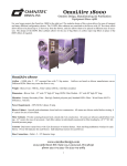
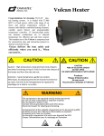
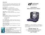
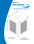
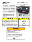
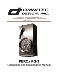
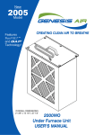
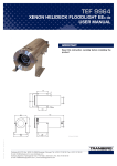
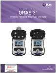
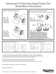
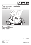
1
OmniAire Portable Air Cleaner
OA1200PAC
The OmniAire Portable Air Purification system purifies the air of airborne contaminants which could be
biological, chemical or particulates. Connected to an isolation containment, it can create small negative
or positive pressure inside the containment. The negative pressure will prevent contaminants from leaking to the outside, while positive pressure would prevent contaminants from outside to enter the containment. All the air pulled from the containment or blown into the containment is purified through 99.99%,
0.3 micron HEPA filter and by high intensity UVGI lights. Optional carbon filters can also be added to
the machine to remove chemical odors.
www.omnitecdesign.com
2125 196th Street SW, Suite 115, Lynnwood, WA 98036
phone 425-774-3257 fax 425-774-4983
Page
OmniAire PAC Instruction Manual 2008
PRODUCT SPECIFICATIONS:
Net weight (with filters)
115 1bs.
Dimensions (LxWxH)
22”x20”x40”
Operating Speeds
Airflow Ratings
Variable Speed Controller
200 to 1100 CFM
Filtration Stages
3-4
99.99% 0.3µ HEPA Filter, Metal Frame, Medical Grade
Standard
Cabinetry
Aluminum
Closed End Rivet Construction
Yes
Silicon Sealed Seams before Riveting
Yes
Push Handle, Polyurethane
One
Casters*
4 Swivel 3”
Motor Horse Power
3/4 hp
Circuit Requirements (Volts/Hz)
115 VAC/60 Hz
Maximum Operating Amps
Thermal Overload Protection
7 Amps
Yes
Pressure Gauge
0-3” W.C.
Optional Accessories:
Intake/Exhaust Manifold 10” diameter ring
Hose clamp, 10” diameter
Flex hose 10” diameter
Stainless Steel Quick Clamp
*Optional 10” Wheels combined with 3” Casters
PARTS:
OA1200PAC HEPA Filtration System
HEPA filter—99.99% @ 0.3 micron, Size 16” x 16” x 12”
Primary filter—40% efficiency pleated filter, Size 16” x 16” x 2”
OPTIONAL FILTERS:
OdorGuard 200 - Carbon Pleated Filter, Size 16” x 16” x 2”
OdorGuard 600—Carbon Fiber Filter pad, Size 16” x 16” x 2”
OdorGuard 750 Plus— Carbon/Alumina/Potassium permanganate filter pad, Size 16” x 16” x 2”
CONFORMS TO UL STD 507
CERTIFIED TO CAN/CSA STD C22.2 NO. 113-M1984
3067108
Page 2
OmniAire PAC Instruction Manual
INSTRUCTIONS
Unpacking:
Carefully check the unit for damage. Remove the exhaust cover grill and check the HEPA filter. It should be
seated, the filter should be flush with the mounting brackets and the brackets should be compressing the filter
down.
The optional Intake Manifold (see Figure 1) provides flex hose connection and holds the primary pleated filter in
place. Intake Manifold can be used on intake or exhaust side in place of the screen. The manifold is secured by
four thumb screws.
Operation:
While the OmniAire PAC machine can operate outside the containment, it is recommended to protect it from the
rain and dirty environment. For the following operation instructions, we are assuming that the machine is
located inside the enclosure. If the machine is located outside the containment, the flex hose connections
would be reversed.
To create positive pressure inside the containment, more air has to be pumped in than leaks out. Connect the
flex hose from the outside to the Intake Manifold on the suction side of the machine. The outside air is pulled
through primary/secondary filter under a negative pressure. This prevents leakage of untreated air into the
containment. Then the air passes through blower and over the UVGI lights, where it is sterilized and pushed
through the HEPA filter to remove any particulates. The pure air stream, diffused by HEPA is then exhausted
into the containment . The plastic sides of the containment should be bowed out to indicate positive pressure.
The speed of the machine can be adjusted to meet your required number of air exchanges and the positive
pressure.
To maintain negative pressure inside the containment in reference to ambient pressure, more air has to be
exhausted out than leaks into the containment. Install the Intake Manifold on the outlet side of the machine and
connect the flex hose to the outside. All the air exhausted to the outside is treated by UVGI lights and by HEPA
filter. The plastic walls of the containment will be bowed in, indicating negative pressure. By increasing fan
speed, the pressure inside the containment becomes less than the outside pressure.
As the doors to containment open, the pressure will temporarily change and return to normal when the doors
close. The higher the speed, the faster the room will return to desired pressure. As the HEPA filter loads with
dust, the speed will have to be increased to reach the same airflow and to maintain the desired pressure inside the
containment.
The PAC HEPA Filtration system must always operate with the HEPA filter in place to prevent
contamination of the area and electrical overload of the motor.
Operating UV Germicidal Lights
UVGI lights are installed in the compartment facing the HEPA filter. The air passing by the UVGI lights is
sterilized and the bio-contaminants captured on the HEPA are killed or deactivated.
The UVGI lights should be turned on before the fan starts to run and should stay on after the air blower is
stopped to complete the sterilization of the HEPA filter. The proper operation of the UVGI lights is monitored
by UVGI and BALLAST indicating LEDs which turn on when the UVGI lights are on.
Operating the PAC System:
The PAC system should be connected to containment outlet with flex duct to create a negative or positive
pressure in the room. The machine can also provide air purification as a self standing unit if desired.
Page 3
OmniAire PAC Instruction Manual 2008
INSTRUCTIONS (Continued)
Before starting the blower, turn on the UVGI lights. Check that the Ballasts and Lamps status lights came on. We
recommend leaving the UVGI light on for another 10 minutes, after the air flow is turned of to sterilize the inside of the
compartment and the intake side of the HEPA filter.
The start and speed of the machine is controlled by the toggle switch HIGH / SPEED CONTROL and the variable
SPEED CONTROLLER knob.
To start the machine in the highest speed, place the toggle switch in HIGH position. To start the machine at reduced
speed, place the toggle switch in SPEED CONTROL position and turn the knob clockwise from OFF to start the
blower. The machine starts at HIGH SPEED and the speed is reduced by turning the knob clockwise to desired air
flow.
The machine can be switched between the desired controlled speed setting and the highest speed at any time by toggle
switch being moved between SPEED CONTROL and HIGH. The toggle switch overrides the SPEED CONTROLLER knob setting and runs the blower at its highest speed. This is also used as a quick check of HEPA filter loading and
required filter change (see Maintenance).
Maintenance:
Mechanical and Electrical The motor and blower do not require any maintenance when the machine is operated with the primary filter in place.
CAUTION: In rare instances the blower wheel may become unbalanced. If severe vibration is present, stop operation and investigate the cause.
The UVGI lights should last over 15,000 hours of operation. There are two high intensity lights UVGI lights and two
ballasts. The LED indicating lamps turning OFF will indicate a light tube or ballast failure. The UVGI tubes and ballasts can be accessed by removing the HEPA filter. Do not look directly into the UVGI lamps, this could damage
your eyesight.
Filter Replacement When replacing the HEPA filter, proper care should be taken to wear a respirator in combination with the necessary PPE
if contaminated with hazardous material. The filter should be disposed of in an appropriate manner based on the contaminants it was exposed to. The HEPA filter element (see Figure 2) is held in place by metal tabs and can be accessed
from the top of the unit. To remove the element, remove the metal grate, unscrew the nuts on the tabs (see Figure 3) and
remove the tabs. Lay the machine down on the handle and slide the element out. Slide the new filter element into place
with the gasket side of the HEPA filter facing the blower unit. Make sure that the HEPA filter is seated well against the
internal flange. Place the machine back in the upright position, replace the filter tabs and nuts and tighten to where the
filter is flush with the mounting brackets. Do not over tighten the bolts as this may crack the gasket. When replacing the
HEPA filter, the primary filter should also be replaced.
The primary filter should be checked or replaced monthly. To access the filter, remove the manifold or gate and install a
new pleated filter. Observe the air flow arrow on the filter.
The HEPA filter efficiency of 99.99% will not degrade when the filter is loaded with dust, but the air flow will be reduced. The HEPA filter should be replaced when:
1. The air flow from the machine is not sufficient to maintain the desired pressure in enclosure.
2. The machine must run in high speed all the time to maintain the desired pressure, which causes excessive noise.
3. HEPA filter is more than 80% loaded.
NOTE: The loading of the filter can be checked by switching the machine to HIGH speed after replacing the primary
filter and reading the pressure gauge “WC”. With all filters clean, the gauge should indicate 1.2” to 1.3” WC. A reading
of 2.6” WC indicates the filter is 80% plugged and should be replaced.
Page 4
2008
OmniAire PAC Instruction Manual
Figure 1. View of the OmniAire PAC
Manifold Installation:
Intake Manifold rests in a bottom
channel and is secured by four
thumb screws.
Intake Manifold has
replaced the intake
screen
Figure 2. HEPA Filter Installed in the Unit
HEPA filter element
mounting tab
Figure 3. Close up of tabs for HEPA element
HEPA Filter
Element
Page 5
Intake/Exhaust Manifold and
Flex Duct (Optional)
Primary Filter
Element
OmniAire PAC Instruction Manual 2008
REFERENCE MATERIALS:
Page 6
OmniAire PAC Instruction Manual
OmnniAire Portable Air Cleaners for First Response Shelters
OmniAire PAC with HEPA and UVGI lights have been designed specifically to meet CDC requirements for clean,
filtered air in a medical environment. Each air filtration system is equipped with a medical grade, metal frame,
HEPA filter element that has been factory tested and certified as 99.99% efficient at 0.3 microns.
The OMNIAIRE PAC units can be paired with Environmental Containment Units to provide a comprehensive
solution by providing a durable, standardized, prefabricated containment for quick emergency response..
Available Models
OmniAire 800 PAC: Compact size, variable airflow; 150-600 CFM, Weight: 75 lbs
Size: 36”H X 15”W X 15”D
OmniAire 1200 PAC: Versatile, variable air flow for larger areas; 200-1100 CFM, Weight: 115 lbs,
Size: 40”H X 23”W X 20”D with wheels
OmniAire 2000PAC: Most powerful model with the largest range of variable airflow; 200-1800 CFM,
Weight: 125 lbs, Size: 40”H X 24”W X 29”D with wheels
Optional Wheel/Caster combination
Page 7
OmniAire PAC Instruction Manual 2008