1
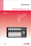
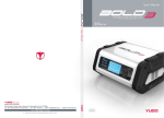
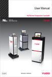
HEAD OFFICE & FACTORY
169-4, Gujang-Ri, Paltan-Myun, Hwasung-City, Gyeonggi-Do, 445-911 Korea
TEL : + 82 31 350 2525 FAX : + 82 31 354 7446
e-mail : [email protected] / [email protected](Asia) / [email protected](Europe & America)
Website : www.yudo.com
Hot Runner System
Take-Out Robot
Factory Automation (Plastics)
HEAD OFFICE & FACTORY
78Blk, 5Lot, 648-4, Gojan-Dong, Namdong-Gu, Incheon, 405-817 Korea
TEL : + 82 32 450 4500 FAX : + 82 32 818 8111 / + 82 32 818 8222
e-mail : [email protected] Website : www.yudostar.com
HEAD OFFICE & FACTORY
78Blk, 5Lot, 648-4, Gojan-Dong, Namdong-Gu, Incheon, 405-817 Korea
TEL : + 82 32 450 7800 FAX : + 82 32 819 3200
e-mail : [email protected] Website : www.yudosuns.com
Auxiliary System
Factory Automation
(Gantry, Bar Feeder, Etc.)
HEAD OFFICE & FACTORY
345-40, Gasan-Dong, Gumchon-Gu, Seoul, 153-802 Korea
TEL : + 82 2 818 8570 FAX : + 82 2 838 6767
e-mail : [email protected] Website : www.yudorobotics.com
▣ Local Office
BUSAN OFFICE
TEL : + 82 51 304 1711
FAX : + 82 51 304 1713
DAEGU OFFICE TEL : + 82 53 383 3734
FAX : + 82 53 383 3736
▣ Subsidiaries
▣ Subsidiaries
JAPAN
YUDO JAPAN CO., LTD.
TEL : + 81 3 6400 4071 FAX : + 81 3 6400 4072
e-mail : [email protected]
- Osaka Office
TEL : + 81 6 6338 9571 FAX : + 81 6 6338 9572
PORTUGAL
YUDO (CHINA) CO., LTD. (柳道實業有限公司)
TEL : + 852 2344 5180 FAX : + 852 2344 5018
e-mail : [email protected]
SPAIN
YUDO TRADING CO., LTD. (柳道貿易有限公司)
TEL : + 86 769 8539 4466 FAX : + 86 769 8539 4455
e-mail : [email protected]
ROMANIA
CHINA
YUDO TRADE COMPANY LTD. TIANJIN
TEL / FAX : + 86 22 88298279
Mobile : + 86 22 60321560 e-mail : [email protected]
YUDO-WANCO (SUZHOU) HOT RUNNER SYSTEMS CO., LTD.
TEL : + 86 512 6504 8882 FAX : + 86 512 6504 6886
e-mail : [email protected]
YUDO SHANGHAI
TEL : + 86 21 5059 3818 FAX : + 86 21 6855 6363
e-mail : [email protected]
TAIWAN
YUDO-WILSON CO., LTD.
TEL : + 886 3 409 1250 FAX : + 886 3 409 1280
e-mail : [email protected]
FRANCE
TURKEY
ITALY
GERMANY
GWANGJU OFFICE
TEL : + 82 62 953 4711
FAX : + 82 62 954 0846
YUDO HOT RUNNER SYSTEMS LDA.
TEL : + 351 244 575810 FAX : + 351 244 575819
e-mail : [email protected]
YUDO FRANCE
TEL : + 33 2 3277 4200 FAX : + 33 2 3253 4655
e-mail : [email protected]
YUDO IBERICA S. L.
TEL : + 34 93 715 81 22 FAX : + 34 93 715 81 25
e-mail : [email protected]
YUDO ROMANIA
TEL / FAX : + 40 213 272 115
e-mail : [email protected]
YUDO TURKEY
TEL : + 90 212 320 9563 FAX : + 90 212 320 9569
e-mail : [email protected]
YUDO MR-TECH S.R.L.
TEL : + 39 02 995 51 78 FAX : + 39 02 995 85 74
e-mail : [email protected]
YUDO GERMANY GMBH.
TEL : + 49 2359 50 92 04 FAX : + 49 2359 50 92 05
e-mail : [email protected]
WANCO INDUSTRIAL PTE. LTD.
TEL : + 65 6264 1166 FAX : + 65 6268 5645
e-mail : [email protected]
MALAYSIA
MAWANCO SDN BHD.
TEL : + 60 3 8945 2127 FAX : + 60 3 8945 2133
e-mail : [email protected]
YUDO HOT RUNNER INDIA PVT. LTD.
TEL : + 91 250 245 1155~6 FAX : + 91 250 245 1158
e-mail : [email protected]
IRAN
YUDO IRAN
TEL : + 98 21 2367655 FAX : + 44 1989 566010 (U.K.)
Mobile : + 98 912 2776072 e-mail : [email protected]
THAILAND
WANCO INDUSTRIAL (THAILAND) CO., LTD.
TEL : + 66 2 757 4989 FAX : + 66 2 757 4988
e-mail : [email protected]
YUDO INC.
VIETNAM
WANCO INDUSTRIAL CO., LTD. (VIETNAM REP. OFFICE)
TEL : + 84 8 935 1207 FAX : + 84 8 843 9409
e-mail : [email protected]
AUSTRALIA &
NEWZEALAND
STM AUSTRALIA PTY. LTD.
TEL : + 61 3 9885 9795 FAX : + 61 3 9885 2756
e-mail : [email protected]
ISRAEL
ASI-AFASPEM ISRAEL LTD.
TEL : + 972 4 680 2770 FAX : + 972 4 680 2770
Mobile : + 972 544 340360
e-mail : [email protected]
GERMANY
MKT MOLLENBERG GMBH.
TEL : + 49 6162 4077 FAX : + 49 6162 2482
e-mail : [email protected]
AUSTRIA
PROTEC
TEL : + 43 1 259 5917 FAX : + 43 1 259 5918
EURO INTERNET HOLDINGS S.A.
TEL : + 48 22 843 0579 FAX : + 48 22 33 90 246
e-mail : [email protected]
- HQ
TEL : + 1 614 873 1300 FAX : + 1 614 873 6873
e-mail : [email protected] / [email protected]
- Central Division
TEL : + 1 630 529 7487 FAX : + 1 630 529 7469
Mobile : + 1 630 605 9119 e-mail : [email protected]
- Mid-Western Division
Mobile : + 1 937 478 9039 e-mail : [email protected]
CANADA
- Eastern & Canada Division
TEL : + 1 905 304 1680 FAX : + 1 905 304 9934
Mobile : + 1 905 512 6358 e-mail : [email protected]
MEXICO
- Western & Mexico Division
TEL : + 1 805 480 4922 FAX : + 1 805 432 1680
Mobile : + 1 805 432 5319 e-mail : [email protected]
BRASIL
U.K.
PAULO ENG. LTD.
TEL : + 55 11 3392 5775
e-mail : [email protected]
YUDO (U.K.) LTD.
TEL : + 44 1989 763423 FAX : + 44 1989 566010
e-mail : [email protected]
▶We reserve the right to change specifications without notice.
MODEL : CGF 560
Instruction Manual
▣ Agencies
SINGAPORE
INDIA
U.S.A.
TEMPERATURE
CONTROLLER
POLAND
RUSSIA
SOUTH AFRICA
CS PLASTECH
TEL : + 7 495 737 9575 FAX : + 7 495 236 3221
e-mail : [email protected]
HESTICO PTY. LTD.
TEL : + 27 11 768 5228 FAX : + 27 11 885 1693
e-mail : [email protected]
Ver. 4.5 MN CGF560 English
English
USER’
S MANUAL
TEMPERATURE CONTROLLER
CGF 560 Series
Thank you for using YUDO product.
Before using the product, please read this instruction manual
carefully to avoid any damage due to improper usage.
If you have any questions, please do not hesitate to contact
our Head Office or your nearst YUDO Office.
CGF-560S
MICOM CONTROLLER
2
CONTENTS
1.Items to check before using the Controller & Operation Procedure
2.Basic Structure of Controller
3.Outline of Controller
1)PID Controller
2)Auto Tuning
3)Output Method
4.Controller Unit Specification
5.Name of Component
6.Operation Modes
1)AUTO Mode
2)STAND-BY Mode
3)MANUAL Mode
7.Menu Setting
1)User's Setting Menu
2)Supplier's Setting Menu
8.Error Code Display Function
9.Integrated Control Function
10.Connector & Cable
1)How to wire a Heater and T/C in Connector
2)Standard Specification Option
3)Options
11.Diagram for Terminal Connection and Structure
12.Electric Wiring Diagram
1)240V 3 Phase 3 Line Type
2)380V/414V 3 Phase 4 Line Type
3)240V 1 Phase 2 Line Type
13.Wiring Modification Method
1)How to convert in order to use Power Input AC380V/415V from AC240V
2)How to convert in order to use Power Input AC240V from AC380V/415V
14.Default Value
1)Default Value of User's Menu
2)Default Value of Supplier Menu
15.Security Marks
16.Check Point for Trouble Shooting
3
4
5
5
6
7
7
8
15
16
17
19
19
21
22
22
23
USER’
S MANUAL
TEMPERATURE CONTROLLER
1. Items to check before using the Controller &Operation Procedure
2. Basic Structure of Controller
Installation Condition : The bottom side is blocked for the safety.
1) Check the wiring status of the connector attached to the mold and the type of T/C.
2) Check if the power lines are separated from the T/C lines, and they are arranged in order.
3) Check if the trunk specification fits to the Controller.
4) Check connection and wiring state of the trunk.
5) Check resistance and insulation state of the heater, then check if T/C wire is disconnected.
6) After the mold is fixed at the injection machine, connect the trunk.
7) Check if the Power Switches of the Main & Units are off.
8) If Input Voltage (240V/380V) fits to the controller voltage specification, connect Power
Cable. (Input power voltage is noted on the label of the controller case. If the power
input voltage does not fit to that written on the label, ask a territory office and correct the
controller wiring. False wiring can cause malfunction of the controller and damage on
3. Outline of Controller
the unit).
The controller is a device that has a function to maintain the desired
9) Make it sure to earth ground wire of the controller. (Neglect to earth the ground wire
temperature consistently by sensing the state of Hot Runner System by use
(green line) can cause damage to fuse and Triac due to noise voltage)
of high-intellectual computer system named MICOM and input proper power.
10) Turn on the Main Power Switch first.
It has several important functions for precise temperature control.
11) Then, turn on the Unit Power switch.
12) Set to the appropriate temperature.
13) Check if the desired temperature is reached and stabilized.
1) PID Control
is a method in order to maintain temperature at the set temperature
accurately by controlling Output Power reflecting proportion, integration, and
differentiation values.
CAUTION : To prevent possible malfunction of the temperature
control modules, the cooling fan MUST OPERATE AT ALL TIMES.
4
5
USER’
S MANUAL
TEMPERATURE CONTROLLER
2) Auto Tuning
is a function to extract the governing factors through analyzing capacity of the
5.Name of Components
heaters and heat constant of the mold (characteristics of latent heat and
released heat). It helps precise control of temperature regardless of
CGF-560S
MICOM CONTROLLER
environmental change.
1. SOFT LED
2. OUT LED
3. PV FND
4. SV FND
3) Output Method can be changed depending on environment.
■ PWM mode : Precise temperature control can be achieved. But electric
noise is bigger than that in SSR mode.
5. SET
6. MODE
7. UP
8. DOWN
9. SEL
■ SSR mode : Electric noise is small, but the specific temperature controlling
ability is inferior to PWM mode
10. AUTO LED
11. STAND-BY LED
12. MANUAL LED
13. MODULE Handle
14. MODULE Power Switch
15. MODULE Lock Bolt
4. Controller Unit Specification
■ Indoor use.
■ Power Input Voltage : AC 85V-250V,
50/60Hz, 15A
Displays SOFT operation
Displays Power Output State
Displays Measured Temperature (Red
4 DIGIT-Position Value)of Hot Runner
System
Displays the Set Temperature
(Green 4 DIGIT-Set Value)of Hot
Runner System
Enter Key.
Mode Change Key.
Value Increase Key.
Value Decrease Key.
AUTO, STAND-BY MANUAL function
conversion key.
Displays Auto Mode is selected
Displays Stand-by Mode is selected
Displays Manual Mode is selected
■ Load Capacity : 15A , 50W-1650W(110V), 100W-3300W(220V)
■ Output Type : PWM(Pulse Width Modulation), SSR(Solid State Relay)
■ Sensor Type : Thermocouple (J, or K)
■ Temperature Setting Range : 100¡C ~ 400¡C, 212¡F ~ 752¡F
■ Temperature Stability :
–0.5% (Full Scale)
■ Temperature Control Type : PID CONTROL
■ Surrounding temperature : -10¡C~50¡C
6. Operation Modes
1) AUTO Mode
Normal operation mode in which the temperature is controlled and maintained
automatically in accordance with the Set Degree.
■ Display conversion : When
key is pressed, the display on SV is
converted as the following order;
[Set Temperature]=>[Output %]=>[Ampere] =>[Set Temperature]
■ Altitude : up to 2000m
■ Over Voltage Categories II
■ Degree of Mobility : Plug-in module
■ F1, F2:250V-15A (Special Fuse)
F3:250V-1A
2) STAND-BY Mode Down the Output Power to the Given Rate for the given time, when it is needed
to stop production for a while on the way or production.
■ Holding
key for 1 second in AUTO mode will convert it into STAND-BY
Mode
■ Temperature setting value (SV) is changed into % rate on the basis of the Set
Temperature during Stand-by mode is working.
6
7
USER’
S MANUAL
TEMPERATURE CONTROLLER
■ Output power is reduced to maintain at the STAND-BY Temperature.
■ STAND-BY Mode will finish after the given time, and move into AUTO
Mode
1-1) AL-H (High Limit Alarm Function)
On the basis of the Set Temperature, when the temperature become higher
than Setting Value, the AL-H function is operated.
■ When
User’
s can adjust Power Output by using
and
key for
3) MANUAL Mode Emergency Manual Operation at his will.
■ When
key is held for 3 seconds, AL-H is displayed on PV, and the
High Limit Value for AL-H is displayed on SV.
■ The value can be set through 00~99 by using
key is pressed twice, for 1 seconds each at the Auto Mode, it
turns into Manual mode
,
key, and the
Initial Value is set as 50 at the factory.
■ To save as Set Value, press
and
keys together.
■ If sensor detect any Disconnection of Thermocouple (tC.oP), or
Thermocouple Short (tC.St), it is converted into Manual mode
automatically for a emergency operation mode.
■ Setting Value(%) can be modified with
,
keys.
1-2) AL-L (Low Limit Alarm Function)
On the basis of the set temperature, when the temperature is lower than the
Low Limit Setting Value, the AL-L function is operated.
■ For the first push
key for 3seconds, then press the key once again.
■ AL-L will be displayed on PV, and the Setting Value for the AL-L will be
7. Menu Setting
displayed on SV.
■ The value can be set through -99~00, by using
1) User's Setting Menu
,
key,
and the Initial Value is set as -50 at the factory.
User's setting menu diagram
■ To save as Set Value, press
and
keys together.
Ex) In case SV(Temperature Setting) is set as 200¡C, AL-H(High Limit
Alarm) as 50¡C, AL-L(Lowest Limit Alarm) as -50¡C :
=>AL-H start at 250¡C of measured temperature, AL-L at 150¡C
■ Press
■
key for 3 seconds in order to start User’s setting menu.
key is used for selecting functions,
and
key for ON/OFF,
keys for change parameter.
■ To save as Set Value, press
and
keys together. But also
Present Valve is replaced automatically as Set Value unless any key is
pressed for 5 seconds.
■ Modifying Set Value must be done under LOCK OFF Mode.
8
9
USER’
S MANUAL
TEMPERATURE CONTROLLER
■ Choose ON or OFF with
1-3) STBY (STAND-BY Setting)
(1)t(STAND-BY Time Setting)
Hold
■ To save, press
and
key.
keys together.
key for 1 seconds and find AL-H is displayed on PV.
Then press it twice more until Stby will be displayed on PV.
■ For the conversion between Hour and Minute, press
1-5) ID (Channel Setting-Option)
key.
■ Stand-by Time can be adjusted from 0 (minutes) till 9 hours 59 minutes by
use of
,
keys.
Units. The computer in Central Control Office could control each Unit
according to it’s own ID number.
■ Integrated Management System must be installed additionally in order to
(2)P(STAND-BY Temperature Setting)
■ At the state of Stand-by Time setting, Push
key to convert into Stby
Temperature Setting Mode.
■ The % rate on the basis of Set Temperature is displayed on SV.
■ The value can be set in the range of 00-99% with
■ To save as Set Value, press
This is provided to help the Integrated Management for many Controller
and
,
keys.
keys together.
Ex) In case SV(Temperature Setting) is set as 200, t(Stand-by Time) as
use Integrated Management Function(Option for CGF-570 model).
■ Hold
key for 3 seconds until AL-H is displayed on PV.
■ Press it 5 times more, until -id- is displayed on PV, then the channel ID is
displayed on SV
■ The value can be set from 00 to 63 with
■ To save, press
and
,
keys.
keys together.
1hour(1:00), P(Standby Temperature%) to P.75 :
=> Stand-by Mode is operated for 1 hour and the Temperature for Standby
Mode is set as 140¡C(75% x 200¡C).
2) Supplier's Setting Menu
Supplier's setting menu diagram
1-4) LOCK (Key S/W Locking device)
■ Press
and
■ Press
for selecting functions,
■ Hold
■ Press
key for 3 seconds, and find AL-H is displayed on PV.
■ Press it 4 more times until LOCK is displayed on PV, then you can see the
OFF on SV.
key for ON/OFF,
and
keys together, to save the value. But also it will be
saved automatically after 5 seconds, unless any other key is pressed
afterwards.
■ Setting must be done under LOCK OFF Mode
10
and
keys for setting parameters.
This is a function to prevent from the change of parameter by mistakes of
user.
keys together, for 3 seconds.
11
USER’
S MANUAL
TEMPERATURE CONTROLLER
2-1) -IN- (Sensor selecting function)
2-4) SOFT (Soft START setting)
Type of Thermocouple can be selected to measure the Heater Temperature.
This helps to avoid humidity-caused damage in heater, by outputting 1~30%
■ Hold
of Input Power for 1 minute at the beginning of Power Supply, in order to
and
keys for 3 seconds together. Then - IN - will be
displayed on PV, and J or K (sensor type) will be displayed on SV (YUDO
check connection state of a heater and sensors, and start smooth control
Standard Specification is mainly J for export, and K for domestic)
action at low heat state.
■ Sensor Type can be selected with
■ To save, press
and
key.
■ Hold
keys together.
and
keys for 3 seconds at the same time.
Then - IN - will be displayed on PV.
■ Press
key three more times to display SoFt on PV and on/oFF on
SV.
■ SOFT START (ON/OFF) can be selected with
2-2) C-F(Celsius and Fahrenheit degrees Selection)
■ To save, press
and
key.
keys together.
Each Celsius or Fahrenheit degrees can be selected for temperature units.
■ Hold
and
keys for 3 seconds at the same time, then
- IN - will be displayed on PV.
■ Press
This is provided to detect malfunction of the heater(disconnection).
key again to display C-F on PV and CdSP/FdSP (selected
temperature display type) on SV.
■ Temperature unit can be selected by
■ To save, press
and
2-5) HC-H (High Limit Current Setting)
It displays "HtSt" alarm sign, and stops output, when the current becomes
bigger than the high limit .
key.
keys together.
■ Hold
and
keys for 3 seconds at the same time.
Then - IN - will be displayed on PV.
■ Press
key 4 times more to display HC-H on PV and the High Limit
Current Value on SV.
2-3) UNIT(Temperature display Unit Settiing)
■ The value can be changed by use of
This is a function to select Temperature Units displayed. You can choose
■ To save as Set Value, press
and
,
key.
keys together.
1.0 or 0.1 for temperature units.
■ Hold
and
keys for 3 seconds together. Then - IN - will be
displayed on PV.
■ Press
This is a function to detect malfunction of the heater (disconnection). It
key two times more to display the corresponding unit on PV,
and 1.0 or 0.1(Temperature setting unit) will be displayed on SV.
■ Temperature units can be selected with
■ To save, press
2-6) HC-L (Low Limit Current Setting)
and
key.
keys together.
displays "Ht-oP" alarm sign, and stops output when the current is smaller
than the Low Limit.
■ Hold
and
keys for 3 seconds at the same time, then -IN- will be
displayed on PV.
■ Press
key 5 times more to display HC-L on PV, and the lowest limit
current value on SV.
12
13
USER’
S MANUAL
TEMPERATURE CONTROLLER
■ The value can be changed by use of
■ To save as Set Value, press
and
,
key.
keys together.
■ Press
key 7 times more to display HSCI on PV , and
PWM/SSR(Output Method) on SV.
■ Output method can be selected by pressing
2-7) Error Code saving function
■ To save, press
and
key.
keys together.
Error Codes are saved in memory in order of sequence.
■ Hold
and
keys for 3 seconds at the same time.
Then - IN - will be displayed on PV.
■ Press
6 times more to find - Er - on PV, and the stored Error Code
on SV.
■ Error Code can be saved up to 20 cases.
■ The other content can be displayed in sequence, when pressing
or
key is repeated.
ERROR OCCURRENCE SIGN
NO
ERROR SIGN
1
tC.oP
DESCRIPTION
Sensor Disconnection
2
tC.St
Sensor Short-Circuit
3
tC.rE
Sensor Polarity Reverse
4
AL-H
High Limit Alarm
5
AL-L
The Low Limit Alarm
6
Ht.oP
Heater Disconnection
7
Ht.St
Heater Short
8
tr.St
Triac Short
9
FU-1
Fuse 1 Disconnection
10
FU-2
8. Error Code Display Function
No
Description
Error classification
- Disconnection, Short, or Reversed Polarity of Sensor
can be checked. When Disconnection or Short is
detected, it is converted into Manual Operation Mode
automatically, and Power Output will be continued to
maintain at the Set Temperature. This function helps
to prevent interruption in production due to
malfunction of a sensor, and Output Power can be
adjusted manually at will.
- On error occurance, Sensor Disconnection(tC.oP),
Sensor Short(tC.St), and Sensor Reversed(tC.rE)
could be displayed on PV. When the problem is
solved, power must be put again to recover Normal
Operation.
Fuse 2 Disconnection
2-8) Selecting Output Method
PWM or SSR are available depending on the user’s choice considering
1
environment.
■ Hold
and
keys for 3 seconds at the same time.
Malfunction on
Temperature
Sensor
Then - IN - will be displayed on PV.
14
15
USER’
S MANUAL
TEMPERATURE CONTROLLER
Description
No Error classification
2
Malfunction on
heater
- Disconnection, Short Circuit, and Over Current of
heater can be detected. Short status of Output
Device(SSR,TRIAC, RELAY) can be checked also.
- On error occurrence, Heater Disconnection(Ht-oP),
Heater Short(Ht-St), and TRIAC short(tr-St) could be
displayed on SV. When the problem is solved, power
must be put again to recover Normal Operation.
3
Fuse
Disconnection
- In case the fuse blown out, related fuse number is
displayed on SV.
- When the problem is solved, power must be put again
to recover Normal Operation.
10. Connector and Cable
Connector means a component attached to the end part of cable in order to
make it easy to connect / disconnect the wire to the mold / controller. Various
kinds of connectors are used depending on load capacities.
Standard Spec. : Integrated wire(Power+T/C)
9. Integrated Control Function (optional)
Central Control for every modules in the frame box can be executed
effectively, with only one switch handling, i.e. STAND-BY or LOCK for every
Optional Spec. : Separated wire(Power, T/C)
module could be controlled simultaneously.
This function is available for CGF570(optional) model only.
1) AL/RE (Alarm RESET Function)
When buzzer works with corresponding error codes in one or more modules
. You can stop the sound of the buzzer with only one handling (Only alarm
buzzer will stop. But it doesn’t mean that the cause of the error is removed).
1) How to wire a heater and T/C in connectors
16P Male standard connector
(2 ZONE~4 ZONE)
2) STBY (Integrated STANDBY function)
In order to stop the production for a while on the way of normal operation,
you can select this function to reduce the Power Supply, with only one
handling.
3) LOCK (LOCK ON function)
This is a security function to prevent from any modifications of setting. You
can convert all modules into Lock ON/OFF Mode with only one handling.
NOTE:# NO:ZONE NUMBER
16
17
24P Male standard connector
(5 ZONE~24 ZONE)
USER’
S MANUAL
TEMPERATURE CONTROLLER
11. Diagram for Terminal Connection and Structure
2) Standard specification
Female connector is attached to the mainframe, and YUDO supply it with 4
pin, 16 pin and 24 pin as same to the following standard.
NO
CONTROLLER
CONNECTOR
QUANTITY
1
1 ZONE
4P Round Jack
1 EA
2
2 ZONE
16 P
1 EA
3
3 ~ 4 ZONE
16 P
1 EA
4
5 ~ 6 ZONE
24 P
1 EA
5
7 ~ 8 ZONE
24 P
2 EA
6
9 ~ 12 ZONE
24 P
2 EA
7
13 ~ 16 ZONE
24 P
3 EA
8
17 ~ 20 ZONE
24 P
4 EA
9
21 ~ 24 ZONE
24 P
4 EA
3) Options
As for option in wiring, Separated power lines from that of T/C can be
selected depending on customer’s preference. But also the other connector
out of YUDO standard could be equipped when those are supplied from
12. Electric Wiring Diagram
customer. In case that, a cable is fabricated according to special order,
Controller Connector must be fabricated in accordance with the Cable
Specification.
24P FeMale heater connector
240V 3Phase 3 Line Type
24P Male T/C connector
As for Zone No.:Please refer to the standard spec.
18
19
USER’
S MANUAL
TEMPERATURE CONTROLLER
13.Wiring modification method
380V/414V 3Phase 4 Line Type
YUDO Temperature Controller operates with supply voltage 220~240V AC.
But even in case of supply voltage 380~415V AC 3phase 4 line, by re-wiring as shown
below, 220~240V AC can be taken between one phase(R, S or T) and Neutral(N).
YUDO Temperature Controller be supplied with wiring for supply voltage 220~240V AC
unless special instruction. Please check the current wiring.
Caution) Before re-wiring, make sure AC main power OFF and Power Switch OFF on controller.
Re-wiring for supply voltage 380V AC from wiring for supply voltage 220V AC
Supply
voltage
220V
Controller
220V
Supply
voltage
380V
Controller
220V
1. Power off
2. Open the back cover of controller
3. Separate all 3 blue-sleeved wires from L1,L2 and L3
4. Plug all 3 blue-sleeved wires into N
240V 1 Phase 2 Line Type
Re-wiring for supply voltage 220V AC from wiring for supply voltage 380V AC
Supply
voltage
380V
Controller Supply
voltage
220V
220V
Controller
220V
1. Power off
2. Open the back cover of controller
3. Separate all 3 blue-sleeved wires from N
4. Plug blue-sleeved RED wire into L1
5. Plug blue-sleeved WHITE wire into L2
6. Plug blue-sleeved BLACK wire into L3
Warning) Do NOT plug PE wire into N. Plugging PE wire into N may cause damage of
controller, for which YUDO will not take responsibility.
20
21
USER’
S MANUAL
TEMPERATURE CONTROLLER
14. Default Value
16. Check Points for the Trouble Shooting
1) Default value of user's menu
NO
MENU
VALUE
1
SV(Setting temperature)
200¡C
2
AL-H(High Limit Alarm)
50¡C
3
AL-L(Low Limit Alarm)
-50¡C
t(Stand-by time)
1.00(1hour)
P(Stand-by
temperature rate)
75%(150¡C)
4
STAND-BY
5
Lock
OFF
6
-Id-
CH00
2) Default Value of Supplier Menu
NO
MENU
VALUE
1
-In-(Sensor Type)
J or K(optional)
2
C-F(Celsius/Fahrenheit)
Mainly CdSP(domestic)/FdSP(foreign)
3
Unit(Temperature Unit)
1.0
4
SoFt(Soft start Function)
On
5
HC-H(High Limit Current)
C16.0
6
HC-M(Minimum Current)
C00.2
7
-Er-(Error History)
0.1-0
8
HSCI(Output Method)
PWM
Phenomenon
No
1 tC.oP on PV
2
tC.St on PV
3
tC.rE on PV
4
Ht.oP on SV
5
Ht.St on SV
6
tr.St on SV
7
FU-1 on SV
8
FU-2 on SV
Temperature rises
continuously
10 Temperature drops
continuously
9
11 Severe temperature
Check point
- Check T/C wire with tester
- When disconnected, replace it
- Check if T/C wire is mal-contacted at connector
- Sensor(T/C) wire is short on output
or pressed by mold
side
- +/- polarity of sensor(T/C) is changed - Check connection and change polarity of T/C at
connector attached to mold
- Check resistance of heater with tester, if it is
- Heater was disconnected
blown out replace heater
- Short circuit in heater or short in heater - Check short circuit of heater or short in heater
line with tester
wire
- Make wiring so that capacity of heater may lower
- Capacity of heater is too high(15A or
then 15A.
more)
- TRIAC attached to heat radiator board - Check pin in TRIAC
- 2 or 3 pins may be in short circuit
is damaged
- Replace F-1 fuse.(250V 15A)
- F-1 fuse is disconnected by
momentary over-current
- Replace F-2 fuse.(250V 15A)
- F-2 fuse is disconnected by
momentary over-current
- Check pin in triac.
- TRIAC attached to heat radiation
- 2 or 3 Pins may be in short circuit
board of controller is damaged.
- Change fuse
- FS1 or FS2 fuse blown out
- Check resistance of heater with tester
- Heater blown out
- Check connection of heater
- Heater wire disconnection
- Check sensor disconnection
- Sensor(T/C)disconnection
- Check contact state of sensor
- sensor contact is unstable
- Check sensor type
- sensor type is different each other
Probable Cause
- Sensor(T/C) was disconnected
(Deviation between set
Temp. & Sensing Temp)
12 Controller temperature rises, - T/C wire is pressed by mold or it s coat - Check and replace T/C wire
but heater in actual mold is
is peeled, so as to contact mold or line
over heated
15. Security Marks
DANGEROUS VOLTAGE INSIDE
DISCONNECT AC POWER BEFORE SERVICING
22
13 Setting temperature of
controller equals with
present temperature, but the
heater in actual mold is
overheated or cold
- T/C (Sensor)type between mold and
controller is different
EX:CA(K)→IC(J), IC(J)→CA(K)
23
- Make T/C(sensor)type of mold equal with that of
controller