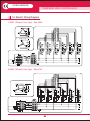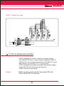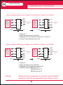
1
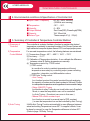
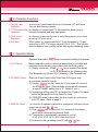
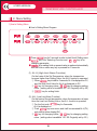
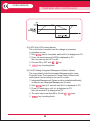
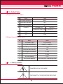
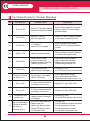
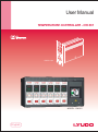
User Manual
TEMPERATURE CONTROLLER - CW 661
CW 661 Unit
MODEL : CW 661
English
USER MANUAL
TEMPERATURE CONTROLLER
CW 661
Thank you for using YUDO product.
Before using the product, please read this instruction manual
carefully to avoid any damage due to improper usage.
If you have any questions, please do not hesitate to contact
our Head Office or your nearst YUDO Office.
2
CONTENTS
1. Items to check before using Controller & Operation ············ 4
2. Structure of Controller ························ 5
3. Name of Components ······················· 5
4. Environmental Conditions & Specification of Controller Unit ········ 6
5. Sunmmary of Controller & Temperature Control Method ········· 6
1) Sunmmary of Controller
2) Temperature Control Method
3) Auto Tuning
6. Protective Functions ························ 7
7. Operation Modes ·························· 7
1) AUTO Mode
2) STAND-BY Mode
3) MANUAL Mode
8. Menu Setting ··························· 8
1) User's Setting Menu
2) Supplier's Setting Menu
9. Reset Function·························· 16
10. Integrated Control Function(Options) ················· 16
11. Connector and Cable ······················· 17
1) How to wire Heater and T/C in Connector
(1) Standard Specification
(2) Options
12. Diagram for Unit and Structure ···················· 18
13. Error Code Display Function ···················· 19
14. Electric Wiring Diagram ······················· 20
1) 220V (3 Phase 3 Line Type) * Max 240V
2) 380V (3 Phase 4 Line Type) * Max 414V
3) 240V (1 Phase 2 Line Type)
15. Wire modification Method ······················ 21
1) Wire modification Method from 3 Phase 3 Line AC220V to 3 Phase 4 Line AC380V
2) Wire modification Method from 3 Phase 4 Line AC380V to 3 Phase 3 Line AC220V
16. Default Value··························· 23
1) Default Value of User's Menu
2) Default Value of Supplier Menu
17. Safety Marks ··························· 23
18. Check-Points for Trouble Shooting ··················· 24
3
USER MANUAL
TEMPERATURE CONTROLLER
1. Items to Check before using Controller & Operation
1) Check the wiring status of the connector attached to the
mold and the type of T/C.
2) Check if the power lines are separated from the T/C lines,
and they are arranged in order.
3) Check if the trunk specification fits to the Controller.
4) Check the connection and wiring state of the trunk.
5) Check resistance, insulation state and disconnection of
Heater & T/C.
6) After the mold is fixed on the injection machine, connect the trunk.
7) Check if the Power Switches of the Main & Units are off.
8) If Input Voltage (220V/380V) fits the controller voltage specification,
connect Power Cable. (Input power voltage is noted on the label
of the controller case. If the power input voltage does not fit to that
written one on the label, Contact a territory office and correct
the controller wiring. False wiring can cause malfunction of
the controller and damage on the unit).
9) Make sure to earth ground wire of the controller.
(Neglect to earth the ground wire (green line) can cause damage
to Fuse and Triac due to noise voltage)
10) Turn on the Main Power Switch first.
11) Then, turn on the Unit Power switch.
12) Input the setting temperature value.
13) Check if the controller operates well. (Heat-up stabilization)
CAUTION
(1) To prevent possible malfunction of the temperature control
modules, the cooling fan MUST OPERATE AT ALL TIMES.
(2) Main power switch should be off in case of changing Unit,
unless it can cause malfunction control.
4
2. Structure of Controller
▶Installation Condition : The bottom side is blocked for the safety.
3. Name of Components
1. PV FND
Displays Measured Temperature
(Red 4 Digit-Position Value)of Hot Runner System
Displays the Set Temperature
(Green 4 Digit-Set Value)of Hot Runner System
Temperature unit Setting value display
Displays SOFT operation
Displays Power Output State
Temperature sensor (TC) Setting value display
Displays Auto Mode is selected
Displays Standby Mode is selected
Displays Manual Mode is selected
Operation switch, User Mode operation key
Value Increase Key
Value Decrease Key
Changing cipher key
Supplier's Menu
2. SV FND
3. ℃/℉ LED
4. SOFT LED
5. OUT LED
6. J/K LED
7. AUTO LED
8. STANDBY LED
9. MANUAL LED
10. MODE
11. ▲
12. ▼
13. SET
*. SET+MODE
14. SEL/SAVE
Select mode (AUTO, STANDBY, MANUAL) &
save the changes
15. Handle
16. Power Switch
17. Lock Bolt
※Caution. Keypad is made of Silicon rubber. Don't touch the keypad by Drill, Ballpoint pen and the sharp edged things.
5
USER MANUAL
TEMPERATURE CONTROLLER
4. Environmental conditions & Specification of Controller Unit
■ Input Power / Frequency
■ Temperature
■ Humidity
■ Output Method
■ Capacity
■ Sensor Type
AC 85 ~ 250V, 50/60Hz
(50/60Hz auto sensing)
-10℃ ∼ 50℃
0 ~ 90%
Zero Cross(SSR), Phase Angle(PWM)
15A, 1Zone/Unit
Thermocouple IC(J) / CA(K)
5. Summary of Controller & Temperature Controller Method
1) Summary of
Controller
The controller is a device that has a function to maintain the desired
temperature consistently by sensing the state of Hot Runner System with
high-intellectual computer system named CPU and input proper power.
2) Temperature
Control Method
For accurate temperature control, the following features are maintained.
(1) Temperature Range : 40℃ ~ 400℃ / 104℉ ~ 752℉
(2) Accuracy : ±0.1℃
(3) Calibration of Temperature deviation : It can calibrate the difference
between actual & Setting temperatures manually.
(4) Temperature control by : PIDD control
① PIDD control
Is a method in order to maintain temperature at the set
temperature accurately by controlling output power reflecting
proportion, integration, and differentiation values.
② PIDD Auto Tuning control
- Auto Tuning
Is a function to extract the control constant through analyzing
the capacity of heaters and the heat constant of the mold. It helps
to make precise temperature control regardless of environmental change.
- Relay (ON/OFF) Tuning
Is a function to relay Tuning by one touch button-on in Supplier's
Mode, in case the temperature can not be controlled
by Auto Tuning. ( Overshoot can occur in this case )
- Manual PID control constant input
Is a function to control by manual input of PID constant.
( in case the temperature can not be controlled by Auto Tuning )
3) Auto Tuning
It fulfills Auto Tuning Function automatically in case difference between
actual and setting Temperature is over 50℃ In supplier's Mode, It can
be done by manual, In case the Temperature diference is below 50℃
(Refer to page 15-Relay Tuning)
6
6. Protective Functions
1) Ground Fault
Inspection
Is a function to self-inspect short-circuit between H/T and frame
Ground, and stop input power.
2) T/C Disconnection Is a function to inspect itself T/C disconnection, short-circuit or
inspection
reverse connection, and stop input power.
3) Over current
Inspection
Is a function to stop input power to avoid damages by over current
in case of H/T shot-circuit.
4) Soft-start
When power on, output starts from 1% and increases by 1% per
second up to 50%. The output stays at 50% till 110℃. This function
prevents heaters from humidity-caused damage by preheating slowly.
7. Operation Mode
Operation Mode select :
key is converted by holding for 2 seconds.
1) AUTO Mode
Normal operation mode in which the temperature is controlled and
maintained automatically in accordance with the Setting value.
(1) Display conversion : When
key is pressed, the display
on SV is converted as the following order.
[Set Temperature]=>[Output %]=>[Ampere] =>[Set Temperature]
2) STANDBY Mode
Down the Output Power to the Given Rate for the given time,
in production pause for a while.
(1) Holding
key for 2 seconds in Auto mode will convert it
into STANDBY Mode. ( Manual Mode is automatically converted,
in case STANDBY setting time is "0". Default 1 hour )
(2) Temperature setting value(SV) is changed into % rate on the basis
of the Set Temperature during Stand-by mode.
(3) STANDBY mode finishes after the given timeis up, and moves
to AUTO Mode. (Refer to page 9)
3) MANUAL Mode
Is a function to operate by manual on emergency that user can set
output volume with
,
key.
(1) Push
key 2 times each for 2 seconds in Auto Mode,
and it will be converted into Manual Mode.
(2) This function is automatically converted in case of
tC.oP, tC.St, tC.rE, Ht.St, Ht.oP, triac short-circuit.
(3) Available to change setting value(%) with
,
key.
7
USER MANUAL
TEMPERATURE CONTROLLER
8. Menu Setting
1) User's Setting Menu
▶User's Setting Menu Diagram
■ Press
key for 3 seconds in order to start User's Setting menu.
■
key is for Selecting Function and,
,
key is for
changing parameter.
■
is for setting finish or present value is replaced automatically
with Set Value unless any key is pressed for 5 seconds.
(1) AL-H (High Limit Alarm Function)
On the basis of the Set Temperature, when the temperature
become higher than Setting Value, the AL-H function is operated.
① When
key is held for 3 seconds, AL-H is displayed on PV,
and the High Limit Value for AL-H is displayed on SV.
②
key for changing cipher,
,
key for changing setting
value. ( setting value is available 00 - 99. Originally set by 50 )
③
key for setting finish.
(2) AL-L (Low Limit Alarm Function)
On the basis of the set temperature, when the temperature is lower
than the Low Limit Setting Value, the AL-L function is operated.
① For the first push
key for 3seconds,
AL-H is displayed on.
② Push
key once more, and it will be converted AL-L(PV)
with setting value display(SV)
③
key for changing cipher,
,
key for changing setting
value. ( setting value is available -99 - 00. Originally set by -50 )
8
④
key for setting finish.
⑤ Ex) In case SV(Temperature Setting) is set as 200℃,
AL-H(High Limit Alarm) as 50℃,
AL-L(Lowest Limit Alarm) as -50℃ :
▶AL-H start at 250℃ of measured temperature, AL-L at 150℃
ON
ON
ON
ON
ON
ON
(3) StbY (STANDBY Setting)
① t (STANDBY Time Setting)
- Hold
key for 3 seconds and find AL-H is displayed
on PV. Then press it
key twice more until Stby
will be displayed on PV.
- STANDBY Time can be adjusted from 0 (minutes) till
9 hours 59 minutes by use of
,
keys.
② g (STANDBY Temperature Setting)
- At the state of STANDBY Time setting, Push
key to
convert into Stby Temperature Setting Mode.
- STANDBY MODE temperature value will be displayed on SV.
key for changing cipher,
,
key for changing setting
value. ( setting value is available 00 - 200.)
key for setting finish.
③ Ex) In case SV(Temperature Setting) is set as 200,
t (STANDBY Time) as 1hour (1:00),
g (STANDBY Temperature%) to g.60 :
▶ STANDBY Mode operating time is 1 hour with
140℃(200℃(setting temperature)-60℃(g.60) setting temperature range.
9
USER MANUAL
TEMPERATURE CONTROLLER
(4) LOCK (Key S/W Locking device)
This is a function to prevent from the change of parameter
by mistakes of user.
① Hold
key for 3 seconds, and find AL-H is displayed on PV.
② Press it 4 more times until LOCK is displayed on PV,
then you can see the OFF on SV.
③ Choose ON or OFF with
,
key.
④
key for setting finish.
(5) Unit ID Setting (Integrated Management System-Option)
This is provided to help the Integrated Management for many
Controller Units. The computer in Central Control Office could
control each Unit according to it's own ID number.
① Integrated Management System must be installed additionally
in order to use Integrated Management Function
② Hold
key for 3 seconds until AL-H is displayed on PV.
③ Press it 5 times more, until -id- is displayed on PV,
then the channel ID is displayed on SV
④ The value can be set from 00 to 63 with
,
keys.
⑤
key for setting finish.
10
2) Supplier's Setting Menu
▶Supplier's Setting Menu Diagram
■ Hold
and
keys for 3 seconds at the same time.
■
key is for Selecting Function and,
,
key is for
changing parameter.
■
is for setting finish or present value is replaced automatically
as Set Value unless any key is pressed For 4 seconds.
■ Setting is available only in LOCK OFF status.
(1) -IN- (Sensor selecting function)
Type of Thermocouple can be selected to measure
the Heater Temperature.
① Hold
and
keys for 3 seconds together.
Then - IN - will be displayed on PV, and
IC(J) or CA(K) (sensor type) will be displayed on SV
② Sensor Type can be selected with
,
key.
③
key for setting finish.
(2) C-F(Celsius and Fahrenheit degrees Selection)
Each Celsius or Fahrenheit (℃/℉) degrees can be selected
for temperature units.
11
USER MANUAL
TEMPERATURE CONTROLLER
① Hold
and
keys for 3 seconds at the same time,
then - IN - will be displayed on PV.
② Press
key again to display C-F on PV and
CdSP/FdSP (selected temperature display type) on SV.
③ Temperature unit can be selected by
,
key.
④
key for setting finish.
(3) UNIT(Temperature display Unit Settiing)
This is a function to select Temperature Units displayed.
You can choose 1.0 or 0.1 for temperature units.
① Hold
and
keys for 3 seconds together.
Then - IN - will be displayed on PV.
② Press
key two times more to display the corresponding
unit on PV, and 1.0 or 0.1(Temperature setting unit) will be
displayed on SV.
③ Temperature units can be selected with
,
key.
④
key for setting finish.
(4) SOFT (SOFT START setting)
① Hold
and
keys for 3 seconds at the same time.
Then - IN - will be displayed on PV.
② Press
key three more times to display SoFt on
PV and on/oFF on SV.
③ SOFT START (ON/OFF) can be selected with
,
key.
④
key for setting finish.
(5) HC-H (High Limit Current Setting)
This is provided to detect malfunction of the heater(disconnection).
It displays "HtSt" alarm sign, and stops output, when the current
becomes bigger than the high limit .
① Hold
and
keys for 3 seconds at the same time.
Then - IN - will be displayed on PV.
② Press
key 4 times more to display HC-H on PV and
the High Limit Current Value on SV.
③ The value can be changed by use of
,
key.
④
key for setting finish.
* HtSt error can occur, In case HC-H Setting Value is lower
than Heater Capacity itself (Setting value is 20C)
12
(6) HC-L (Low Limit Current Setting)
This is a function to detect malfunction of the heater (disconnection).
It displays "Ht-oP" alarm sign, and stops output when the current
is smaller than the Low Limit.
① Hold
and
keys for 3 seconds at the same time,
then -IN- will be displayed on PV.
② Press
key 5 times more to display HC-L on PV,
and the lowest limit current value on SV.
③ The value can be changed by use of
,
key.
④
key for setting finish.
* Ht.oP error can occur in case HC-L Setting value is bigger
than Heater capacity itself (Setting value is 0.2C)
(7) Error Code Saving Function
Error Codes are saved in memory in order of sequence.
① Hold
and
keys for 3 seconds at the same time.
Then - IN - will be displayed on PV.
② Press
6 times more to find - Er - on PV,
and the stored Error Code on SV.
③ Error Code can be saved up to 20 cases.
④ The other content can be displayed in sequence,
when pressing
or
key is repeated.
※ ERROR CODE TABLE
No
1
2
3
4
5
6
Error Sign
7
8
9
10
11
12
13
Description
Sensor Disconnection
Sensor Short-Circuit
Sensor Polarity Reverse
Heater Disconnection
Heater Short-Circuit
Ground Fault
or Triac Short-Circuit
Fuse 1 Disconnection
Fuse 2 Disconnection
High Limit Alarm
Low Limit Alarm
Power Frequency Error
Triac Short-Circuit
USER MANUAL
TEMPERATURE CONTROLLER
(8) Selecting Output Method
Zero Cross(SSR) or Phase Angle(PWM) are available depending
on the user's choice considering environment.
① Hold
and
keys for 3 seconds at the same time.
Then - IN - will be displayed on PV.
② Press
key 7 times more to display HSCI on PV , and
PWM/SSR(Output Method) on SV.
③ Output method can be selected by pressing
,
key.
④
key for setting finish.
Zero Cross
SSR
Output (%)
100%
50%
25%
Phase Angle
PWM
(9) Temperature Variation Correction
Is a function to control Temperature difference between
setting temp. and actual temp.
① Press
+
key at the same time, and PV is
converted to “IN” status.
② Press
key 8 times, and it is converted to tnPA status.
It is possible to input the temp. difference value. Then, the
difference value is gradually decreased.
③
,
for changing setting value.
④
key for setting finish.
(10) Relay Tuning
It is used in case of bad controlling condition or when hard to
set PID value
① Press
+
key at the same time, and PV is
converted to “IN” status..
② Press
key 12 times, and it is converted to rELY
status with ON/OFF selections.
③
,
key for changing value
④
key for setting finish
14
(11) PID Manual Control
It is possible to control PID constant manually, in case it is still
hard to controll well after Auto Tuning and Relay Tuning
① Press
+
key at the same time, and PV is
converted to “IN” status.
② Press
key 9,10,11 times, and it is converted to
LP-P(I,d) status.
* Press Modu key 9 times for "P" value change.
* Press Modu key 10 times for "I" value change.
* Press Modu key 11 times for "D" value change.
③
,
key for changing value
④
key for setting finish
⑤ PID Manual operates after pressing
key only
in case nAnC is ON status.
(12) Manual Controlling Operation (nAnC)
It is used to operate PID setting value (11)
① Press
+
key at the same time, and PV is
converted to “IN” status..
② Press
key 13 times, and it is converted to nAnC
status with ON/OFF selections.
③
,
key for changing value
④
key for setting finish
(13) Frequency Check
This is a function which displays error message (Fr.Er) in case
of unstable input voltage frequency, controller actively displays
the message after checking status of unstable voltage.
① Press
+
key at the same time for 3 secs,
and PV is converted to "IN" status.
② Press
key 14 times more to display Fr.Er on
PV, and (ON/OFF) on SV.
③ Originally set by "Off", turn on Frequency Check
function to check and display the status of factory's
main voltage frequency. The function can be turned
off in case of inconvenience by frequent error message.
15
USER MANUAL
TEMPERATURE CONTROLLER
(14) Noise Check
Although Triac is normal status, tr.St error can be displayed
when noise occurs by unstable input voltage. In case of tr.St
error, the status of Triac and connection of heaters must be checked.
The function can be optionally turned off when same errors
repeatedly occur in normal status.
① Press
+
key at the same time for 3 secs,
and PV is converted to "IN" status.
② Press
key 15 times more to display PU.Er on PV,
and (ON/OFF) on SV.
③ Originally set by "ON", and it is insisted to check factory's
main voltage when error displayed. The function can be turned
off in case of inconvenience by frequent error message.
(15) Setting for Cartridge Heater only.
① Press
+
key at the same time for 3 secs to
make PV sign "IN" status.
② Press
key 16 times to change PV sign "HE.At",
SV sign "Hr.Ht/CA.Ht"
③ USE , to select "CA.Ht" and Press
to complete
the setting.
9. Reset Function
This is a function which initializes the setting values of User mode
and Supplier mode. Turn on the power switch pressing both Mode
button and Set button to display rSEt on SV and to initialize all setting
values after displaying countdown on PV (from 3 to 0).
After initializing is finished, main power of Unit automatically turned
off and restored to on status after 3 secs, and all values will
be restored as factory setting.
10. Integrated Control Function (optional)
Central Control for every modules in the frame box can be executed
effectively, with only one switch handling, i.e. STANDBY or LOCK for
every module could be controlled simultaneously.
1) STANDBY
In order to stop the production for a while on the way of normal
operation, you can select this function to reduce the Power Supply,
with only one handling.
16
2) LOCK
This is a security function to prevent from any modifications of setting.
You can convert all modules into Lock ON/OFF Mode with only one
handling.
11. Connector and Cable
Connector means a component attached to the end part of cable in
order to make it easy to connect / disconnect the wire to the mold /
controller. Various kinds of connectors are used depending on load
capacities.
·Standard Spec. : Integrated Wire(Power+T/C)
·Optional Spec. : Separated Wire(Power, T/C)
1) How to wire Heater and T/C in Connectors
24P Male standard connector
(5 ZONE~24 ZONE)
4P Round Jack
#1
T/C
+
4
1
3
2
HEATER
#4
#1
#5
#2
#6
#3
※ NOTE : # NO = ZONE NUMBER
(1) Standard Specification
Female connector is attached to the mainframe, and YUDO
supplies it with 4P(1 Zone), 24P as same to the following standard.
No
1
2
3
4
Zone
1 Zone
2 Zone
3~4 Zone
5~6 Zone
Connector. Quantity
4P Round Jack 1 EA
1 EA
24P
1 EA
24P
1 EA
24P
17
No
5
6
7
8
Zone
7~8 Zone
9~12 Zone
18 Zone
19~24 Zone
Connector
24P
24P
24P
24P
Quantity
2 EA
2 EA
3 EA
4 EA
USER MANUAL
TEMPERATURE CONTROLLER
(2) Options
As for option in wiring, Separated power lines from that of T/C
can be selected depending on customer's preference. But also
the other connector out of YUDO standard could be equipped
when those are supplied from customer. In case that, a cable is
fabricated according to special order, Controller Connector must
be fabricated in accordance with the Cable Specification.
24P FeMale heater connector
24P Male T/C connector
#1
#1
#2
#2
#3
#3
#4
#4
#5
#5
#6
#6
#7
#7
#8
#8
#9
#9
#10
#10
#11
#11
#12
#12
※ As for Zone No.:Please refer to the standard spec.
12. Diagram for Unit and Structure
CT
Triac
RT
SENSOR
(IN PUT)
HEATER
(OUT PUT)
AC 85~250V
(50/60Hz)
G
Fuse 1
Fuse 2
18
Relay
13. Error Code Display Function
No
1
Description
Error Classification
Malfunction on
Temperature Sensor
- Disconnection, Short, or Reversed Polarity of Sensor can be
checked. When Disconnection or Short is detected, it is converted
into Manual Operation Mode automatically, and Power Output will
be continued to maintain at the Set Temperature. This function
helps to prevent interruption in production due to malfunction
of a sensor, and Output Power can be adjusted manually at will.
- On error occurrence, Sensor Disconnection(tC.oP),
Sensor Short(tC.St), and Sensor Reversed(tC.rE) could be
displayed on PV. When the problems solved, power must
be put again to recover Normal Operation.
2 Malfunction on Heater
- Disconnection, Short, or Reversed polarity of sensor can be
checked. When disconnection or short is detected, it is converted
into manual operation mode automatically, and power output will
not be continued for the safety purpose.
- On error occurrence, heater disconnection (HT-oP),
Heater Short(Ht-St) could be displayed on SV. When the problem
solve, power must be put again to recover normal operation.
3
- In case the fuse blown out, related fuse number is displayed on SV.
Fuse Disconnection - When the problem is solved, power must be put again to
recover normal operation.
- The error message of Tr.St and Ground fault(gr.ft) on the PV
when you put the power initially to the controller.
Check the Triac status and if it is ok then please check
the heater status. Please change the heater if heater has
short circuit trouble.
4
Short Circuit in Triac
- In case of short circuit of Triac while operating condition.
it is converted into manual operation mode automatically,
and power output will not be continued for the safety purpose.
On error occurrence, Tr.St could be displayed on PV. When the
problem solve(replacement of Triac), power must be put again
to recover normal operation.
19
USER MANUAL
TEMPERATURE CONTROLLER
14. Electric Wiring Diagram
1) 220V (3Phase 3 Line Type) * Max 240V
2) 380V (3Phase 4 Line Type) * Max 414V
20
3) 240V (1 Phase 2 Line Type)
15.Wiring Modification Method
YUDO Temperature Controller operates with supply voltage
220~240V AC. But even in case of supply voltage 380~414V AC
3phase 4 line, by re-wiring as shown below, 220~240V AC can be
taken between one phase(R, S or T) and Neutral(N).
YUDO Temperature Controller be supplied with wiring for supply
voltage 220~240V AC unless special instruction.
Please check the current wiring.
Caution
Before re-wiring, make sure AC main power OFF and
Power Switch OFF on controller.
21
USER MANUAL
TEMPERATURE CONTROLLER
1) Wire modification Method from 3 Phase 3 Line AC220V to 3 Phase 4 Line AC380V
L1
R
외부
입력전압 S
220 V
T
3상 3선식
L2
NFB
L3
Red
Red
White
White Controller
Black 220 V
Black
NFB
PE(G)
L1
Red
L2
White Controller
220 V
Black
Red
White
Black
L3
N
N
N
N
R
외부
S
입력전압
380 V
T
3상 4선식
PE(G)
PE
PE
1. Power off
2. Open the back cover of controller
3. Separate all 3 blue-sleeved wires from L1, L2 and L3
4. Plug all 3 blue-sleeved wires into N
2) Wire modification Method from 3 Phase 4 Line AC380V to 3 Phase 3 Line AC220V
R
외부
입력전압 S
380 V
3상 4선식 T
N
PE(G)
NFB
L1
Red
L2
White
L3
N
R
외부
입력전압 S
220 V
3상 3선식 T
Controller
220 V
Black
Red
White
Black
L1
L2
NFB
N
PE(G)
PE
L3
Red
Red
White
White Controller
Black 220 V
Black
N
PE
1. Power off
2. Open the back cover of controller
3. Separate all 3 blue-sleeved wires from N
4. Plug blue-sleeved RED wire into L1
WHITE wire into L2
BLACK wire into L3
Warning
.
PE(G) must be ground connection, do not permit to connect the Neutral.
Manufacturer cannot be held responsible for any troubles from Above.
22
16. Default Value
1) Default Value of User's Menu
Value
Menu
No
1 SV(Setting temperature)
200℃
2
AL-H(High Limit Alarm)
50℃
3
AL-L(Low Limit Alarm)
4
STANDBY
-50℃
t (STANDBY time)
1.00 (1hour)
g (STANDBY temperature rate)
50 ( Setting Temp. - 50℃)
5
Lock
OFF
6
-Id-
CH00
2) Default Value of Supplier Menu
No
Menu
Value
1
-In-(Sensor Type)
IC(J) or CA(K)
2
C-F(Celsius/Fahrenheit)
CdSP(℃) / FdSP(℉)
3
Unit(Temperature Unit)
--1.0
4
SoFt(Soft start Function)
On
5
HC-H(High Limit Current)
C 20.0
6
HC-M(Minimum Current)
C 00.2
7
-Er-(Error History)
0.1-0
8
HSCI(Output Method)
Zero Cross(SSR) / Phase Angle(PWM)
17. Safety Marks
DANGEROUS VOLTAGE INSIDE
DISCONNECT AC POWER BEFORE SERVICING
23
USER MANUAL
TEMPERATURE CONTROLLER
18. Check-Points for Trouble Shooting
No
Phenomenon
1
tC.oP on SV
1. Check contact state of Connectors
1. Sensor(T/C) was disconnected
2. Rewire or replace T/C after testing
2. Connector wiring disconnected
by electric tester
2
tC.St on SV
1.Sensor(T/C) wire is
short on output side
3
tC.rE on SV
1. +/- polarity of
sensor(T/C) is changed
4
Ht.oP on SV
1. Heater was disconnected
5
Ht.St on SV
1. Short circuit in heater
or short in heater wire
2. Capacity of heater is too high
(3600W [15A] or more)
1. Check short circuit of heater or
short in heater line with tester
2. Make wiring so that capacity
of heater may lower then 15A.
6
tr.St on SV
1. Triac attached to heat
radiator board is damaged
1. Check pin in Triac
A1 and A2 pins may be in short circuit
7
In case the Triac is
ok above no.6
1. Power supply is not stable
(Noise, Frequency)
1. Check factory power supply
2. Swich off Frequency and Noise
inspection function (Refer to Page 15~16)
8
FU-1 on SV
1. F-1 fuse is disconnected by
momentary over-current
1. Replace F-1 fuse.(250V 25A)
9
FU-2 on SV
1. F-2 fuse is disconnected by
momentary over-current
1. Replace F-2 fuse.(250V 25A)
10
Temperature rises
continuously
1. Triac attached to heat
radiation board of controller
is damaged.
1. Check pin in Triac.
A1 and A2 Pins may be in short circuit
1. FS1 or FS2 fuse blown out
Severe temperature
2. Heater blown out
(Deviation between
3. Heater wire disconnection
set Temp. &
4. Sensor(T/C)disconnection
Sensing Temp.)
5. Cooling water leak
1. Change fuse
2. Check resistance of heater with tester
3. Check connection of heater
4. Check sensor disconnection
5. Check mold cooling water leak
11
Probable Cause
24
Check point
1. Check if T/C wire is loosely contacted
at connector or pressed by mold
1. Check connection and change
polarity of T/C at connector attached
to mold
1. Check resistance of heater withtester,
If it is blown out replace heater
Phenomenon
No
12
Severe temperature
(Deviation between set
Temp. & Sensing Temp)
Check point
Probable Cause
1. sensor contact is unstable
2. sensor type is different
each other
13
1. T/C wire is pressed by mold
Controller temperature
or it's coating is peeled,
rises, but heater in
so as to contact mold or line
actual mold is over
2. Cooling water leak makes
heated
Heaters to have over-current
14
1. T/C (Sensor)type between
Setting temperature of
mold and controller is different
controller equals with
EX
present temperature,
Controller
IC
CA
but the heater in actual
Hot Runner
Overheat
mold is overheated
CA
OK
OK
or cold
IC
1. Check contact state of sensor
2. Check sensor type
1. Check and replace T/C wire
2. Check mold cooling water leak
1. Make T/C(sensor)type of mold
equal with that of controller
Temp. lack
Spare Parts
Triac
FAN
Fuse 1
Fuse 2
EMC Standard
EMC Should be installed on YUDO Case(Fraim) to meet EMC Spec.
25
USER MANUAL
TEMPERATURE CONTROLLER
Global Network
NETHERLANDS
GERMANY
FINLAND
CZECH
POLAND
U.K
FRANCE
SLOVAKIA
ITALY
PORTUGAL
SPAIN
ROMANIA
AUSTRIA
TURKEY
ISRAEL
EGYPT
SYRIA
KOREA
IRAN
JAPAN
CHINA
TAIWAN
BANGLADESH
INDIA
VIETNAM
THAILAND
MALAYSIA
PHILIPPINES
SINGAPORE
INDONESIA
SOUTH AFRICA
AUSTRALIA
ASIA & OCEANIA
CHINA
YUDO TRADING CO., LTD.
Tel : + 86 769 8539 4466
e-mail : [email protected]
YUDO (HONG KONG) ENTERPRISE CO. LTD.
Tel : + 852 2344 5180
e-mail : [email protected]
YUDO TIANJIN OFFICE
Tel : + 86 022 5839 9351
e-mail : [email protected]
YUDO (SUZHOU) H.R.S. CO. LTD
Tel : + 86 512 6504 8882
e-mail : [email protected]
YUDO (SHANGHAI) OFFICE
Tel : + 86 021 5138 6422
e-mail : [email protected]
YUDO (NINGBO) OFFICE
Tel : + 86 574 8711 3033
e-mail : [email protected]
YUDO (QINGDAO) TRADING CO. LTD.
Tel : + 86 532 8765 1698
e-mail : [email protected]
YUDO (QINGDAO) TRADING CO., LTD (WEIHAI) OFFICE
Tel : + 86 631 5672 582
e-mail : [email protected]
YUDO (QINGDAO) TRADING CO., LTD (DAILIAN) OFFICE
Tel : + 86 131 3002 3765
e-mail : [email protected]
KUNSHAN YUDO-SUNS CO LTD.
Tel : + 86 512 5791 0286
TAIWAN
YUDO CO., LTD. (TAIWAN BRANCH)
Tel : + 886 2 2205 6677
e-mail: [email protected]
JAPAN
YUDO JAPAN CO., LTD.
Tel : + 81 3 6400 4071
e-mail : [email protected]
-Osaka Office
Tel : + 81 6 6338 9571
e-mail : [email protected]
-Nagoya Office
Tel : + 81 52 745 0361
e-mail : [email protected]
INDIA
YUDO HOT RUNNER INDIA PVT. LTD.
Tel : + 91 250 245 1155 / 56
e-mail : [email protected]
-Delhi Branch Office
Telefax : +91 120 4549076
e-mail : [email protected]
-Pune Branch Office
Tel : +91 20 30013070
e-mail : [email protected]
-Bangalore Branch Office
Telefax : +91 80 40600700
e-mail : [email protected]
-Chennai Branch Office
Tel : +91 44 39159145
e-mail : [email protected]
26
BANGLADESH
YUDO (BD) PVT. LTD.
Tel : + 88 02 9014 632
e-mail: [email protected]
PHILIPPINES
WANCO INTUSTRIAL INC.
Tel : + 63 949 307 1950
e-mail : [email protected]
SINGAPORE
YUDO WANCO PTE. LTD.
Tel : + 65 6264 1166
e-mail : [email protected]
VIETNAM
HOA VAN HOA. CO.,LTD.
Tel : + 84 43 78 77 179
e-mail : [email protected]
-Hochiminh Office
Tel : + 84 908 81 36 55
e-mail : [email protected]
INDONESIA
WANCO INDUSTRIAL PTE. LTD
Tel : + 62 92299 2850
e-mail : [email protected]
AUSTRALIA
STM AUSTRALIA PTY. LTD.
Tel : + 61 3 9885 9795
e-mail : [email protected]
NEW ZEALAND
STM SALES LTD.
Tel : + 64 9 8206454
e-mail : [email protected]
SYRIA
SAWAS TRADING GROUP
Tel : + 963 21 2254756
e-mail : [email protected]
THAILAND
YUDO WANCO (THAILAND) CO., LTD.
Tel : +66 2 174 7236-40
e-mail : [email protected]
ISRAEL
ASI-AFASPEM ISRAEL LTD.
Tel : + 972 4 6802770
e-mail : [email protected]
MALAYSIA
MAWANCO SND BHD.
Tel : + 60 3 8945 2127
e-mail : [email protected]
IRAN
YUDO.ir
Tel : + 98 (0)21 22066506~7
e-mail : [email protected]
USA
Headquarter
Plant
Subsidiary
Sales Office
Agency
PERU
BRAZIL
NEW ZEALAND
AMERICA & EUROPE & AFRICA
U.S.A.
YUDO INC. (Head Office)
Tel : + 1 614 873 1300
e-mail : [email protected]
-Westem Territory (Sales Office)
Tel : + 1 805 480 4922
e-mail : [email protected]
-Central Territory (Sales Office)
Tel : + 1 630 529 7487
e-mail : [email protected]
-Mid-Western Territory (Sales Office)
Tel : + 1 440 834 0167
e-mail : [email protected]
-Southern Region & Peta Business (Sales Office)
Tel : +1 214 774 4556
e-mail : [email protected]
PORTUGAL
YUDO HOT RUNNER SYSTEMS LDA.
Tel : + 351 244 575 810
e-mail : [email protected]
YUDO EU LDA.
Tel : + 351 244 570 390
e-mail : [email protected]
ITALY
YUDO MR-TECH S.R.L.
Tel : + 39 02 99 551 78
e-mail: [email protected]
POLAND
EUROTECH HOLDING Sp. z o.o.
Tel : + 48 22 843 05 79
e-mail : [email protected]
FINLAND
YUDO Nordic Oy
Tel : + 358 3 616 1847
e-mail : [email protected]
FRANCE
HVDI YUDO FRANCE
Tel : + 33 2 3277 4200
e-mail : [email protected]
GERMANY
YUDO GERMANY GmbH.
Tel : + 49 2359 50 92 04
e-mail : [email protected]
MKT MOLLENBERG GmbH.
Tel : + 49 6162 40 77
e-mail : [email protected]
SPAIN
YUDO IBERICA S.L.
Tel : + 34 93 715 81 22
e-mail : [email protected]
NETHERLANDS
INVENT B.V.
Tel : + 31 (0)13 5705252
e-mail : [email protected]
PERU (CHILE, COLOMBIA)
NOBLE EQUIPMENT & SERVICES CORP.
Tel : + 51 1 615 1400
e-mail : [email protected]
BRAZIL
PAULO ENGENHARIA LTDA.
Tel : + 55 11 3392 5775
e-mail : [email protected]
ROMANIA
ROMOULD YUDO ROMANIA
Tel : + 40 213 272 115
e-mail : [email protected]
SLOVAKIA
YUDO SLOVAKIA s.r.o.
Tel : + 421 335 333 363
e-mail : [email protected]
CZECH
ABUKO s.r.o
Tel : + 420 724 358 612
e-mail : [email protected]
U.K.
YUDO (UK) LTD.
Tel : + 44 1989 763423
e-mail : [email protected]
TURKEY
YUDO TURKEY
Tel : + 90 212 320 95 63
e-mail : [email protected]
AUSTRIA
PROTEC
Tel : + 43 1 259 5917
e-mail : [email protected]
REPUBLIC OF SOUTH AFRICA
HESTICO PTY. LTD.
Tel : + 27 11 786 5228
e-mail : [email protected]
27
EGYPT
C&C CORPORATION
Tel : + 20 2 2516 7926
e-mail : [email protected]
HEAD OFFICE & FACTORY
169-4, Gujang-Ri, Paltan-Myun, Hwasung-City, Gyeonggi-Do, 445-915 Korea
Tel : + 82 31 350 2530 (Overseas Sales Team)
Fax : + 82 31 354 7446
E-Mail : [email protected] Website : www.yudo.com
BUSAN OFFICE
DAEGU OFFICE
GWANGJU OFFICE
GUMI OFFICE
Tel
Tel
Tel
Tel
: +82 51 304 1711
: +82 53 383 4712~3
: +82 62 953 4711
: +82 54 475 5732~3
Fax : +82 51 304 1713
Fax : +82 51 383 4714
Fax : +82 62 954 0846
Fax : +82 54 475 5734
Ver. 1.5 MN CW 661 (10. Dec)
▶ We reserve the right to change specifications without notice.