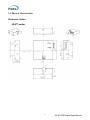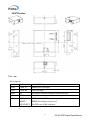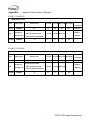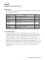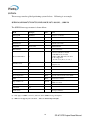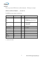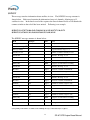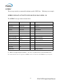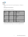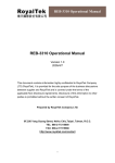
1
GPS Engine Board
SR-87
SiRF Star Ⅲ
V 1.2
User Manual
Website: www.progin.com.tw
E-mail: [email protected]
Specifications subject to
change without notice!
Contents
1. Introduction
1.1 Overview
……………………………………………………..…………. 2
…………………………………………………………………. 2
2. Technical Specifications …………………………………………………… 3
2.1. Electrical Characteristics…………………………………………………. 3
2.2. Environmental Characteristics……………………………………..……… 4
2.3. Physical Characteristics……………………………………………...…..… 5
3. Applications
……………………………………………………………… 7
4. Operation and Test (optional)………………..……………
7
Appendix: Antenna Status sentence …………………………………….. 8
Appendix: Software Specifications
1
…………………………………….. 9
SR-87 GPS Engine Board Manual
1. Introduction
1.1. Overview
Product Introduction
The ProGin SR-87 series GPS modules incorporates high sensitivity, high
performance SiRF StarⅢ chipset solution in a compact design. The module tracks
up to 20 satellites at a time while offering fast time-to-first-fix and 1Hz navigation
update. The unit is very suitable for broad applications such as Handheld, PDA,
PPC or other battery operated navigation system.
Main Features
■ High sensitivity SiRF StarⅢ chipsets.
■ High performance receiver tracks up to 20 satellites.
■ TTL output for GPS command interface.
■ Low power consumption.
■ Average Cold Start time under 42 seconds.
■ On-chip 1Mb SRAM.
■ Reacquisition time 0.1 second.
■ Support accurate 1PPS output signal aligned with GPS timing.
■ Support Standard NMEA-0183 and SiRF Binary protocol.
■ Multi-path mitigation hardware.
■ Built-in a lithium battery enables fast positioning.
■ Compact size (25.4×25.4×7 mm3) for easy integration into hand-held devices.
The SR-87 design utilizes the latest surface mount technology and high level circuit
integration to achieve superior performance while minimizing dimension and power
consumption. This hardware capability combined with software intelligence
makes the board easy to be integrated and used in all kinds of navigation
applications or products. The module communicates with application system via
RS232 (TTL level) with NMEA-0183 protocol.
Ordering information:
SR-87V-P, Vertical MMCX input with 1PPS Time mark output
SR-87V-S, Vertical MMCX input with GPS status indication
SR-87H-P, Horizontal MMCX input with 1PPS Time mark output
SR-87H-S, Horizontal MMCX input with GPS status indication
2
SR-87 GPS Engine Board Manual
2. Technical Specifications
2.1. Electrical Characteristics
2.1.1 General
Frequency
L1, 1575.42 MHz
C/A code
1.023 MHz chip rate
Channels
20 channels all in view tracking
2.1.2 Sensitivity
Tracking
-159 dBm typical
2.1.3 Accuracy (Open Sky)
Position
Time
< 10 meters, 2D RMS
< 7 meters 2D RMS, WAAS corrected
1-5 meters, DGPS corrected
1 microsecond synchronized to GPS time
2.1.4 Datum
Default
WGS-84
2.1.5 Acquisition Rate
Hot start
Warm start
Cold start
Reacquisition
1 sec, average
38 sec, average
42 sec, average
0.1 sec, average
2.1.6 Dynamic Conditions
Altitude
Velocity
Acceleration
Jerk
< 18,000 meters (60,000 feet)
< 515 meters/sec (1000 knots)
<4G
20 meters/sec max
2.1.7 Power
Main power input
Supply Current
Backup Power
3.0 ~ 5.5 VDC input.
< 40 mA
3V rechargeable Lithium battery,
up to 500 hours discharge
3
SR-87 GPS Engine Board Manual
2.1.8 RF Interface
Antenna connector type
MMCX
2.1.9 Serial Port
Electrical interface
Two full duplex serial communication, via RS232,
TTL interface.
Protocol message
NMEA-0183.
Default NMEA
GGA, GSA, GSV, RMC, (GLL, VTG, and ZDA
optional).
4800 baud rate (other rate optional).
8 bits data, 1 stop bit, no parity.
Antenna Status sentence ZANTAX /ZANTA(Optional)
2.1.10 Time
1PPS Pulse, Pulse duration 1µs.
Time reference at the pulse positive edge.
Synchronized to GPS time, ± 1µs.
2.1.11 Weight
< 8g
2.1.12 Recommended External Antenna Specification
Gain
20 dB min (cable loss included)
Noise figure
1.5 dB typical
Current
10 mA typical
Operating Voltage
Confirmed to spec 3.3 ~ 5.5 V
Survival
3.0 ~ 3.3 V
2.2. Environmental Characteristics
Operating temperature range
Storage temperature range
-40 oC to +85 oC
-45 oC to +100 oC
4
SR-87 GPS Engine Board Manual
2.3. Physical Characteristics
Mechanical Outline
SR-87V outline
5
SR-87 GPS Engine Board Manual
SR-87H outline
Unit : mm
Pin assignment
Pin1
VDD
3.0 ~ 5.5 VDC input
Pin2
UART Tx
NMEA serial data output
Pin3
UART Rx
Serial data input
Pin4
NC
Not connect, must be floating for normal operation
Pin5
GND
Ground
Pin6
TIMEMARK/
RESET/
GPS STATUS
TIMEMARK: 1PPS Time mark output (Pulse duration 1µs)/
RESET: Reset Input (Active Low)/
For GPS status (LED) indication
6
SR-87 GPS Engine Board Manual
3. Applications
The SR-87 series engine module is a high performance, ultra low power
consumption, GPS receiver. Applications are as follows:
Car Navigation
Wrist Watch
Solar Operated Device
Marine Navigation
Fleet Management
AVL and Location-Based Services
Radar detector with GPS function
Hand-Held Device for Personal Positioning and Navigation
Ideal for PDA, Pocket PC and Other Computing Devices at GPS Application
4. Operation and Test (optional)
The customers can change the data protocol and communication data baud rate for their
applications using a GPS Viewer software. Installing appropriate viewer program to
host device, you may check the status of the GPS receiver whenever you like to.
Following are standard buttons and operation steps.
(a) Execute the Viewer program. Press the “COM” button to set “Com Port” for this
data link and “Baud Rate” to 4800.
(b) Click “OPEN” to download the received data. Usually one window shows the
NMEA format data stream and another window shows tracked satellite
constellation and signal quality status.
(c) Once the link is successful, click “CLOSE” button to exit the program. However,
you may click the “Cold” button to perform “cold start” testing.
7
SR-87 GPS Engine Board Manual
Appendix:
Antenna Status sentence (Optional)
For SR-87 (ZANTAX)
$ZANTAX,0,0,0,0*xx
Message
Field
Message ID
Antenna Port
Reserved Reserved Reserved Checksum
terminator
Format
$ZANTAX
int
int
int
int
*xx
<CR><LF>
External antenna status:
Message for
Note
ASCII 13,
0: external antenna normal
Reserved Reserved Reserved
specified user
ASCII 10
1: external antenna open/short
Example
$ZANTAX
0
0
0
0
*xx
For SR-87-S (ZANTA)
$ZANTA,0,0,0,0*xx
Message
Field
Message ID
Antenna Port
Reserved Reserved Reserved Checksum
terminator
Format
$ZANTA
int
int
int
int
*xx
<CR><LF>
External antenna status:
Message for
Note
ASCII 13,
0: external antenna normal
Reserved Reserved Reserved
specified user
ASCII 10
1: external antenna open/short
Example
$ZANTA
0
0
8
0
0
*xx
SR-87 GPS Engine Board Manual
Appendix: Software Specifications
NMEA Protocol
The SR-87 software is capable of supporting the following NMEA message formats specifically
developed and defined by SiRF.
NMEA Message Prefix
Format
Direction
$GPGGA
Time, position and fix type data.
Out
$GPGLL
Latitude, longitude, time of position fix and status.
Out
$GPGSA
GNSS DOP and active satellites
Out
$GPGSV
Satellites in view.
Out
$GPMSS
Radio beacon signal-to-noise ratio, signal strength,
frequency, etc.
Out
$GPRMC
Recommended minimum specific GNSS data.
Out
$GPVTG
Speed and course over ground.
Out
$GPZDA
Date and time.
Out
General NMEA Format
The general NMEA format consists of an ASCII string commencing with a ‘$’ character and
terminating with a <CR><LF> sequence. NMEA standard messages commence with ‘GP’ then a
3-letter message identifier. The message header is followed by a comma delimited list of fields
optionally terminated with a checksum consisting of an asterix ‘*’ and a 2 digit hex value
representing the checksum. There is no comma preceding the checksum field. When present,
the checksum is calculated as a bitwise exclusive of the characters between the ‘$’ and ‘*’. As an
ASCII representation, the number of digits in each number will vary depending on the number and
precision, hence the record length will vary. Certain fields may be omitted if they are not used,
in which case the field position is reserved using commas to ensure correct interpretation of
subsequent fields.
9
SR-87 GPS Engine Board Manual
$GPGGA
This message transfers global positioning system fix data. Following is an example.
$GPGGA,161229.487,3723.2475,N,12158.3416,W,1,07,1.0,9.0,M, , , ,0000*18
The $GPGGA message structure is shown below:
Field
Example
Message ID
$GPGGA
GGA protocol header.
UTC Time
161229.487
hhmmss.sss
Latitude
3723.2475
ddmm.mmmm
N/S Indicator
N
N=north or S=south.
Longitude
12158.3416
dddmm.mmmm
E/W indicator
W
E=east or W=west.
Position Fix Indictor
1
0: Fix not available or invalid.
1: GPS SPS mode, fix valid.
2: Differ. GPS, SPS mode, fix valid
3-5: Not supported.
6: Dead Reckoning Mode, fix valid. (1)
Satellites Used
07
Number of satellites used to calculate fix.
Range 0 to 12.
HDOP
1.0
Horizontal Dilution of Precision.
MSL Altitude
(2)
Unit
Notes
9.0
Meter
Altitude above mean seal level.
M
Meter
M stands for “meters”.
Meter
Separation from Geoids can be blank.
Units
Meter
M stands for “meters”.
Age of Diff. Corr.
Second
Age in seconds. Blank (Null) fields when
DGPS is not used.
Units
Geoid Separation
(2)
Diff Ref. Station ID
0000
Checksum
*18
<CR> <LF>
Message terminator.
(1) Only apply to NMEA version 2.3 (and later) in this NMEA message description.
(2) SiRF does not support geoid corrections.
Values are WGS84 ellipsoid heights.
10
SR-87 GPS Engine Board Manual
$GPGLL
This message transfers geographic position, latitude, longitude, and time.
example.
Following is an
$GPGLL,3723.2475,N,12158.3416,W,161229.487,A,A*41
The $GPGLL message structure is shown below:
Field
Example
Unit
Message ID
$GPGLL
GLL protocol header.
Latitude
3723.2475
ddmm.mmmm
N/S Indicator
N
N=north or S=south.
Longitude
12158.3416
dddmm.mmmm
E/W indicator
W
E=east or W=west.
UTC Time
161229.487
hhmmss.sss
Status
A
A: Data valid or V: Data invalid.
Mode
A
A=Autonomous, D=DGPS, E=DR
(Only present in NMEA version 3.00).
Checksum
*41
<CR><LF>
Notes
Message terminator.
11
SR-87 GPS Engine Board Manual
$GPGSA
This message transfers DOP and active satellites information.
Following is an example.
$GPGSA,A,3,07,02,26,27,09,04,15, , , , , ,1.8,1.0,1.5*33
The $GPGSA message structure is shown below:
Field
Example
Unit
Notes
Message ID
$GPGSA
GSA protocol header.
Mode
A
M: Manual, forced to operate in selected 2D
or 3D mode.
A: Automatic switching between modes.
Mode
3
1
2
3
Satellites Used (1)
07
SV on channel 1.
Satellites Used (1)
02
SV on channel 2.
Fix not available.
2D position fix.
3D position fix.
…
..
Satellites Used (1)
SV on channel 12.
PDOP
1.8
HDOP
1.0
VDOP
1.5
Checksum
*33
<CR> <LF>
Message terminator.
(1) Satellites used in solution.
12
SR-87 GPS Engine Board Manual
$GPGSV
This message transfers information about satellites in view. The $GPGSV message structure is
shown below. Each record contains the information for up to 4 channels, allowing up to 12
satellites in view. In the final record of the sequence the unused channel fields are left blank with
commas to indicate that a field has been omitted.
Following is an example.
$GPGSV,2,1,07,07,79,048,42,02,51,062,43,26,36,256,42,27,27,138,42*71
$GPGSV,2,2,07,09,23,313,42,04,19,159,41,15,12,041,42*41
The $GPGSV message structure is shown below:
Field
Example
Unit
Notes
Message ID
$GPGSV
GSA protocol header.
Number of messages (1)
2
Number of messages, maximum 3.
Message number
1
Sequence number, range 1 to 3.
Satellites in view
07
Number of satellites currently in view.
Satellite ID
07
Channel 1, ID range 1 to 32.
Elevation
79
degree
Elevation of satellite, maximum 90.
Azimuth
048
degree
Azimuth of satellite, range 0 to 359.
SNR (C/N0)
42
dBHz
Range 0 to 99, null when not tracking.
Satellite ID
02
Elevation
51
degree
Elevation of satellite, maximum 90.
Azimuth
062
degree
Azimuth of satellite, range 0 to 359.
SNR (C/N0)
43
dBHz
Range 0 to 99, null when not tracking.
Satellite ID
26
Elevation
36
degree
Elevation of satellite, maximum 90.
Azimuth
256
degree
Azimuth of satellite, range 0 to 359.
SNR (C/N0)
42
dBHz
Range 0 to 99, null when not tracking.
Satellite ID
27
Elevation
27
degree
Elevation of satellite, maximum 90.
Azimuth
138
degree
Azimuth of satellite, range 0 to 359.
SNR (C/N0)
42
dBHz
Range 0 to 99, null when not tracking.
Checksum
*71
Channel 2, ID range 1 to 32.
Channel 3, ID range 1 to 32.
Channel 4, ID range 1 to 32.
<CR> <LF>
Message terminator.
(1) Depending on the number of satellites tracked multiple messages of GSV data may be required.
13
SR-87 GPS Engine Board Manual
$GPMSS
This message transfers information about radio beacon signal-to-noise ratio, signal strength,
frequency, etc. Following is an example.
$GPMSS,55,27,318.0,100,1,*57
The $GPMSS message format is shown below.
Field
Example
Unit
Notes
Message ID
$GPMSS
Signal Strength
55
dB
SS of tracked frequency.
Signal-to-Noise Ratio
27
dB
SNR of tracked frequency.
Beacon Frequency
318.0
kHz
Currently tracked frequency.
Beacon Bit Rate
100
Bits per second.
Channel Number (1)
1
The channel of the beacon being used if a
multi-channel beacon receiver is used.
Checksum
*57
MSS protocol header.
<CR> <LF>
Message terminator.
(1) Fields marked in italic red apply only to NMEA version 2.3 (and later) in this NMEA message description.
14
SR-87 GPS Engine Board Manual
$GPRMC
This message transfers recommended minimum specific GNSS data.
Following is an example.
$GPRMC,161229.487,A,3723.2475,N,12158.3416,W,0.13,309.62,120598, ,*10
The $GPRMC message format is shown below.
Field
Example
Message ID
$GPRMC
RMC protocol header.
UTC Time
161229.487
hhmmss.sss
Status
A
A: Data valid or V: Data invalid.
Latitude
3723.2475
ddmm.mmmm
N/S Indicator
N
N=north or S=south.
Longitude
12158.3416
ddmm.mmmm
E/W indicator
W
E=east or W=west.
Speed over ground
0.13
knot
Speed over ground
Course over ground
309.62
degree
Course over ground
Date
120598
Magnetic variation
Mode
(2)
Checksum
(1)
Unit
Notes
ddmmyy, current date.
degree
A
Not used.
A=Autonomous, D=DGPS, E=DR.
*10
<CR> <LF>
(1) SiRF does not support magnetic declination.
Message terminator.
All “course over ground” data are geodetic WGS84 directions.
(2) Fields marked in italic red apply only to NMEA version 2.3 (and later) in this NMEA message description.
15
SR-87 GPS Engine Board Manual
$GPVTG
This message transfers velocity, course over ground, and ground speed.
example.
Following is an
$GPVTG,309.62,T, ,M,0.13,N,0.2,K,A*23
The $GPVTG message format is shown below.
Field
Example
Message ID
$GPVTG
Course (true)
309.62
Reference
T
Course (magnetic)
Unit
Notes
VTG protocol header.
degree
Measured heading
T = true heading
degree
Measured heading
Reference (1)
M
M = magnetic heading (1)
Speed
0.13
Units
N
Speed
0.2
Units
K
K = km/hour.
Mode (2)
A
A=Autonomous, D=DGPS, E=DR.
Checksum
*23
knot
N = knots
km/hr
<CR> <LF>
(1) SiRF does not support magnetic declination.
Speed in knots
Speed
Message terminator.
All “course over ground” data are geodetic WGS84 directions.
(2) Fields marked in italic red apply only to NMEA version 2.3 (and later) in this NMEA message description.
16
SR-87 GPS Engine Board Manual
$GPZDA
This message transfers UTC Time and Date.
Following is an example.
$GPZDA,181813,14,10,2003,00,00*4F
The $GPZDA message format is shown below.
Field
Example
Unit
Message ID
$GPZDA
ZDA protocol header.
UTC Time
181813
Either using valid IONO/UTC or estimated
from default leap seconds.
UTC Day
14
01 to 31, day of month.
UTC Month
10
01 to 12.
UTC Year
2003
1980 to 2079.
Local zone hours
00
Offset from UTC (set to 00).
Local zone minutes
00
Offset from UTC (set to 00).
Checksum
*4F
<CR> <LF>
Notes
Message terminator.
17
SR-87 GPS Engine Board Manual