1
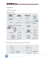
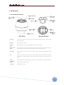
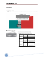
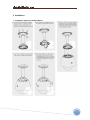
www.cnbtec.com
Outdoor Speed Dome Series IP-XNET
Ver 1.0
INSTALLATION AND OPERATION MANUAL / ISS2000 Series
(3810-0203A)
bâàwÉÉÜ fÑxxw WÉÅx fxÜ|xá |Ñ@åÇxà
This lightning flash with arrowhead symbol is intended to alert
The user to the presence of un-insulated “dangerous voltage”
Within the product’s enclosure that may be of sufficient magnitude
To constitute a risk of electric shock to persons.
This exclamation point symbol is intended to alert the user to
The presence of important operating and maintenance (servicing)
instructions in the literature accompanying the appliance.
⊙ Important Safety Instructions
1. Read Instructions
Read all of the safety and operation instructions before using the product.
2. Retain Instructions
Save these instructions for future reference.
3. Attachments / Accessories
Do not use attachments or accessories unless recommended by the appliance manufacturer as they may cause hazards, damage product and void
warranty.
4. Installation
Do not place or mount this product in or on an unstable or improperly supported location. Improperly installed product may fall, causing serious
injury to a child or adult, and damage to the product. Use only with a mounting device recommended by the manufacturer, or sold with the product.
To insure proper mounting, follow the manufacturer’s instructions and use only mounting accessories recommended by manufacturer.
5. Power Source
This product should be operated only from the type of power source indicated on the marking label.
⊙ Precautions
■ Operating
• Before using, make sure power supply and others are properly connected.
• While operating, if any abnormal condition or malfunction is observed, stop using the camera immediately and then contact your local dealer.
■ Handling
• Do not disassemble or tamper with parts inside the camera.
• do not drop or subject the camera to shock and vibration as this can damage camera.
• Care must be taken when you clean the clear dome cover. Especially, scratch and dust will ruin your quality of camera.
■ Installation and Storage
• Do not install the camera in areas of extreme temperature, which exceed the allowable range.
• Avoid installing in humid or dusty places.
• Avoid installing in places where radiation is present.
• Avoid installing in places where there are strong magnetic fields and electric signal.
• Avoid installing in places where the camera would be subject to strong vibrations.
2
bâàwÉÉÜ fÑxxw WÉÅx fxÜ|xá |Ñ@åÇxà
⊙ Table of Contents
1. Introduction
Features
5
Product & Accessories
7
Parts Name & Functions
8
2. Installation
Dip Switch Setup
9
Installation Using the Wall Mount
11
Installation Using the Pendant Mount
12
Wire Connections
13
3. Operation
Check Points before Operation
15
Preset and Pattern Function Pre-Check
22
Starting OSD Menu
22
Preset
22
Swing
22
Pattern
23
Group
23
Other Functions
24
4. OSD Menu
OSD Display of Main Screen
25
General Rules of key Operation for Menu
26
Main Menu
26
Display Setup
26
Privacy Zone Mask Setup
27
Camera Setup(27x
ISS2765N(P) models)
28
Camera Setup(36x
ISS2965N(P)X
30
Motion Setup
EXview Models)
32
Preset Setup
33
Swing Setup
35
Patten Setup
36
Group Setup
37
System Initialize
39
5. IP Network Part
3
System Administration
40
Operating The Camera
41
Live View
43
Status Window
45
Configuring Users
47
Setting Date & Time
49
Configuring Multi Viewer
51
Configuring PTZ
53
Maintaining Server
55
Generating Log Report
57
Configuring Audio
59
Co n f i gu ri n g Vi de o
61
bâàwÉÉÜ fÑxxw WÉÅx fxÜ|xá |Ñ@åÇxà
Configuring RTP/RTSP
63
Configuring the Network(TCP/IP) parameter
65
Configuring IP Filtering
67
Configuring HTTP
69
Configuring UPnP/DynDNS/Bonjour
71
Configuring CMS
73
Configuring Event Type
75
SMTP Setup
77
ConfiguringFTP
79
Configuring and operating PTZ
81
Configuring Motion Detection Area
83
Configuring Multi view Option
85
6. Specifications
27x (ISS2765N(P)) Models
87
36x (ISS2965N(P)X) EXview Models
88
Dimensional Drawings
89
7. System Models and Related Accessories
System Model Numbers
91
Related Accessories
91
4
bâàwÉÉÜ fÑxxw WÉÅx fxÜ|xá |Ñ@åÇxà
1. Introduction
⊙ Features
■ Camera Specifications
• Image Pick-up Device: 1/4" Interline Transfer CCD
• Zoom Magnification:
27x Optical Zoom, 10x Digital Zoom (Max. 270x Zoom) → Model ISS2765N(P)
36x Optical Zoom, 12x Digital Zoom (Max. 432x Zoom) → Model ISS2965N(P)X
• True Day & Night Function
• Various Focus Mode : Auto-Focus / Manual Focus / SemiAuto Focus.
• Each Preset has its own video configuration, label, relay output setting values.
You can adjust each Preset setting independently.
■ Powerful Pan/Tilt Functions
• Max. 360°/sec high speed pan/Tilt Movement
• Using Vector Drive Technology, Pan/Tilt motions are accomplished in a shortest path. As a result, time to target view is reduced
dramatically and the video on the monitor is very natural to watch.
• For jog operation using a controller, since ultra slow speed 0.05°/sec can be reached, it is very easy to locate camera to desired target view.
Additionally it is easy to move camera to a desired position with zoom-proportional pan/tilt movement.
■ Preset, Pattern, Swing, Group, Privacy Mask and More...
• Max. 127 Presets are assignable and characteristics of each preset can be set up independently, such as white Balance, Auto Exposure, Label,
Digital Outputs and so on.
• Max. 8 set of Swing action can be stored. This enables to move camera repetitively between two preset positions with designated speed.
• Max. 4 of patterns can be recorded and played back. This enables to move camera to follow any trajectory operated by joystick as closely as
possible.
• Max. 8 set of Group action can be stored. This enables to move camera repetitively with combination of preset or pattern or Swing. A Group is
composed of Max. 20 entities of Preset/Patten/Swings.
• Privacy Masks are assignable, not to intrude on other’s privacy. (8 Privacy Zones)
→ Only available with Models (26x)-ISS2465N(P)X, (18x)-ISS2665N(P)X, (27x)-ISS2765N(P) and (36x)-ISS2965N(P)X
■ PTZ(Pan/Tilt/Zoom) Control
• With WEB browser CMS, NVR, cameras can be controlled at the same time.
■ OSD(On Screen Display) Menu
• OSD menu is provided to display the status of camera and to configure the functions interactively.
• The information such as Camera ID, Pan/Tilt Angle, Alarm I/O and Preset can be displayed on screen.
5
bâàwÉÉÜ fÑxxw WÉÅx fxÜ|xá |Ñ@åÇxà
■ Alarm I/O Functions
• 4 alarm sensor inputs and 2 alarm Output relays are available.
• To reject external electric noise and shock perfectly, alarm sensor Input is decoupled with photo coupler and the relay is used for alarm output.
• The signal range of sensor input is from DC 5.0 to 12.0 volts to adopt various applications. Meanwhile, the maximum load of relay contact is
250VAC, 3A or 28VDC, 3A.
• If an external sensor is activated, camera can be set to move to the corresponding Preset position. Meanwhile, the output relay can be
matched to some specific preset positions to do counteractions such as turning on the light or sound the alarm.
■ Reserved Presets for Special Purpose
• Most camera characteristics can be set up easily and directly with reserved preset, not entering into OSD menu. For more information, refer to
“Reserved Preset” in this manual.
■ Easy Installation and Perfect Outdoor Environment Compatibility
• Fans and heaters are built-in camera for cold and hot temperature environment.
Also idealistic mechanical design protects camera from water and dust. (IP 66)
• It is easy to install and maintain camera with terminal for cable connection in brackets.
■ IP Network Control
• supported multiple codec with MJPEG /MPEG4 /H.264.
6
bâàwÉÉÜ fÑxxw WÉÅx fxÜ|xá |Ñ@åÇxà
1. Introduction
⊙ Product & Accessories
■ Basic Components
Optional Accessories(May vary by region) -> Adaptor
■ Other Components (available to be ordered separately) ∙Manual /CD
7
bâàwÉÉÜ fÑxxw WÉÅx fxÜ|xá |Ñ@åÇxà
1. Introduction
⊙ Parts Name & Functions
① Dome Cover
Do not detach protection vinyl from dome cover before finishing all installation process to protect dome cover
from scratches or dust.
② DIP Switch
Sets up camera ID and protocol.
③ Main Body
Enables signals and power to come and go between main body and mount bracket.
Cable
④ Drop Prevention
Spring
⑤ Lockup Screw
This part keeps the camera from dropping during installation and maintenance. After install the Bracket, please,
hang the spring to the drop prevention hook of main body as shown in picture for further tasks.
After assembling main body to bracket, screw main body to bracket to protect them from separation by vibration
and so on.
⑥ Fuse
If the fuse is burnt to protect your came from over-current damage, the fuse have to be replace with new one. The
fuse specification is 250V 2A. however, we recommend consulting with supplier to remove the cause of overcurrent.
⑦ Cabling
During installation, Power, Video, Communication, Alarm I/O cables are connected on to this cables terminal block.
Terminal Block
⑧ Mold Line
Mark to assemble main body to bracket.
⑨ TACT Switch
Network Board Factory reset
8
bâàwÉÉÜ fÑxxw WÉÅx fxÜ|xá |Ñ@åÇxà
2. Installation
⊙ DIP Switch Setup
■ Before installing the camera, you should set the DIP switches to configure the camera ID, communication protocol. Do not use the system upgrade
terminal.
■ Input Sensor Active Type
• When a sensor input is used, its functional type should be set.
There are two types; Normal Open type and Normal Close type.
-Normal Open : Voltage is let out when the sensor is activated
-Normal Close : Voltage is let out when the sensor is not activated
Pin
Switch position
Sensor type
ON
Sensor 1 Normal Close
OFF
Sensor 1 Normal Open
ON
Sensor 2 Normal Close
OFF
Sensor 2 Normal Open
ON
Sensor 3 Normal Close
OFF
Sensor 3 Normal Open
ON
Sensor 4 Normal Close
OFF
Sensor 4 Normal Open
ST1 (Pin 4)
ST2 (Pin 5)
ST3 (Pin 6)
ST4 (Pin 7)
• If a wrong type of sensor is selected, it activates in the opposite way to the sensor input.
9
bâàwÉÉÜ fÑxxw WÉÅx fxÜ|xá |Ñ@åÇxà
■ General LAN/WAN Configuration
10
bâàwÉÉÜ fÑxxw WÉÅx fxÜ|xá |Ñ@åÇxà
2. Installation
⊙
11
Installation Using the Wall Mount
bâàwÉÉÜ fÑxxw WÉÅx fxÜ|xá |Ñ@åÇxà
2. Installation
⊙ Installation Using the Pendant Mount
12
bâàwÉÉÜ fÑxxw WÉÅx fxÜ|xá |Ñ@åÇxà
2. Installation
⊙ Wire Connections
■ Power Connection
• The standard power for the system is 24VAC / 2A.
Please, check the voltage and current capacity of rated power carefully.
■ Video Connection
• Connect With BNC coaxial cable.
■ LAN/WAN Configuration
• For PTZ control, connect this line to router. To control multiple cameras at the same time, TCP/IP communication lines of them is connected in
parallel as shown below.
13
bâàwÉÉÜ fÑxxw WÉÅx fxÜ|xá |Ñ@åÇxà
2. Installation
■ Sensor Input/Relay Output
• Sensor input connection
Before connecting sensors, check driving voltage and output signal type of the sensor.
Since output signal types of the sensors are divided into Open Collector and Voltage Output type in general, the cabling must be done properly after
considering these types.
Also, the sensor type, i.e. “Normal Open” or “Normal Close” in DIP switch in main body of camera must be set properly.
Signal Line
Description
IN COM+
Connect(+)cable of electric power source for sensors to this port as shown in the
circuit above.
IN1 -, IN2 -, IN3 -, In4 -
Connect output of sensors for each port as shown in the circuit above.
• Relay output connection
Maximum allowable electrical load of relay is shown bellow table.
Driving Power
DC
110VAC
220VAC
Max. Capacity
28VDC, 3A
110VAC, 3A
250VAC, 3A
14
bâàwÉÉÜ fÑxxw WÉÅx fxÜ|xá |Ñ@åÇxà
3. Operation
⊙ Check Points before Operation
• Before power is applied, please check the cables carefully.
• If you changed camera protocol by changing DIP switches, the change will be effective after you reboot the camera.
⊙ System Control
•
Logging On
You can log on as an administrator using either Internet browser or ‘CMS’ software.
(This manual will describe about using Internet browser only.)
•
Using Internet Explorer
Type the IP Address of the XPEED-XNET product in the address bar and press enter.
Ex) :
http://192.168.123.100
If the HTTP port has been changed from the default value, enter the new port as shown below:
IP Address of the XPEED-XNET: Port No.
Ex) :
•
http://192.168.123.100:8080
ID and Password
If you are logging in as an administrator, the Log-In box will appear as shown in figure 3-1.
Basic Setup page will appear when you enter id and password.
The default user name and password is “root” and “admin” respectively.
For security purpose, it is recommended to change the administrator’s id and password from their default values. Please be careful not
to forget them or expose them to others. Please refer to [figure 5-5] for detail.
If you forget the administrator’s password, “Factory Reset” is the only way to regain access. However, since this will retrieve all
default settings, you need to configure the network settings using IP installer software again.
15
bâàwÉÉÜ fÑxxw WÉÅx fxÜ|xá |Ñ@åÇxà
Figure 3-1 Log-in window
16
bâàwÉÉÜ fÑxxw WÉÅx fxÜ|xá |Ñ@åÇxà
•
Configuring
PTZ
This configures XPEED-XNET’s PTZ
information,
Click [▷ PTZ Configuration] to open the page shown in Figure 3-2.
Figure 3-2 PTZ Configuration
17
bâàwÉÉÜ fÑxxw WÉÅx fxÜ|xá |Ñ@åÇxà
Field
Sub Field
Description
This moves the viewable area within the active CCD region.
From the center, it can be moved two click positions in the the positive/negative x/y
Direction Key
direction.
This button moves origin point.
Tele/Wide
Near/Far
Iris-/Iris+
set
When push Tele button, camera
go
Zooms In.
When push Wide button, camera go
Zooms Out.
When push
Near button, camera
When push
Far button, camera
go Focus In.
go Focus Out.
When push Iris- button, camera go to close the IRIS.
When push
Iris+ button, camera
go to open the IRIS.
Saves the current position to the values in the Preset Edit box.
del
Deletes the current position to the values in the Preset Edit box.
go
Moves the PTZ to the defined Preset position.
Start to save for Pattern.
End to save for Pattern.
Runs Pattern.
-
Runs
-
Runs defined Group .
-
defined Swing.
Stops running the Pattern, Swing, and Group.
Menu On :
Displays camera
OSD menu in screen.
Menu Off : Displays off for camera OSD menu.
Move or change a OSD item in OSD menu.
Set(Near) : set selected menu function.
Back(Far) : cancel and move to selected menu function.
Pan Speed
Moving Speed Setup
Tilt Speed
Select the Pan Speed of PTZ.
Select the Tile Speed of PTZ.
Set : Applies and Saves selected Pan/Tilt’s Speed .
18
bâàwÉÉÜ fÑxxw WÉÅx fxÜ|xá |Ñ@åÇxà
• Configuring and operating Network PTZ
This controls XPEED-XNET’s PTZ.
Click PTZ button in operator mode to open the page shown in the Figure 3-3.
Figure 3-3 Web Viewer Page
19
bâàwÉÉÜ fÑxxw WÉÅx fxÜ|xá |Ñ@åÇxà
Field
Sub Field
Description
This moves the viewable area within the active CCD region.
From the center, it can be moved two click positions in the the positive/negative x/y
Direction Key
direction.
This button moves origin point.
Tele/Wide
Near/Far
Iris-/Iris+
set
When push Tele button, camera
go
Zooms In.
When push Wide button, camera go
Zooms Out.
When push
Near button, camera
When push
Far button, camera
go Focus In.
go Focus Out.
When push Iris- button, camera go to close the IRIS.
When push
Iris+ button, camera
go to open the IRIS.
Saves the current position to the values in the Preset Edit box.
del
Deletes the current position to the values in the Preset Edit box.
go
Moves the PTZ to the defined Preset position.
Start to save for Pattern.
End to save for Pattern.
Runs Pattern.
-
Runs
defined Swing.
-
Runs defined Group .
-
Stops running the Pattern, Swing, and Group.
20
bâàwÉÉÜ fÑxxw WÉÅx fxÜ|xá |Ñ@åÇxà
• OSD menu selection
• This page setups Preset, Pattern,and Swing, and Group of PTZ general functin or select Alarm I/O using OSD menu.
• OSD ON/OFF : Click Menu On/Off
• OSD
Cursor :
button in OSD menu of control group at this page.
Using arrow button in OSD Menu Control Tab, moves OSD menu cursor.
Figure 3-4 OSD menu selection
21
bâàwÉÉÜ fÑxxw WÉÅx fxÜ|xá |Ñ@åÇxà
3. Operation
⊙ Preset and Pattern Function Pre-Check
• Check how to operate preset and pattern function with web viewer or CMS in advance to operate camera function fully when using web viewer
or CMS.
•
Refer to the following table.
<Go Preset>
Input[Preset Number] and press [Preset go] button.
<Set Preset>
Input[Preset Number] and press [Preset set] button.
<Run Pattern>
Input[Pattern number] and press [Pattern run] button.
<Set Pattern>
Input[Preset Number] and press [Pattern red] button.
⊙ Starting OSD Menu
• Function : Using the OSD menu, Preset, Pattern, Swing, Group and Alarm I/O function can be configured for each application.
• Enter Menu :
press Munu On Button in setting Web page
⊙ Preset
• Function
Max. 127 positions can be stored as Preset position. The Preset number can be assigned from 1 to 128, but 95 is reserved for
starting OSD menu.
Camera characteristics (i.e. White Balance, Auto Exposure) can be set up independently for each preset. Label should be blank
and Relay Outputs should be set to OFF as default. “Camera Adjust” should be set “GLOBAL” as default. All characteristics can
be set up in OSD menu.
• Set Preset
<Set Preset> [1~128]
• Run Preset
<Go Preset>
• Delete Preset
To delete Preset, use del del-button or OSD menu
[1~128]
⊙ Swing
• Function
By using Swing function, you can make camera to move between 2 Preset positions repeatedly.
When swing function runs, camera moves from the preset assigned as the 1st point to the preset assigned as the 2nd point
in CW(Clockwise) direction. Then camera moves from the preset assigned as the 2nd point to the preset assigned as the 1st
point in CCW(Counterclockwise) direction.
In case that the preset assigned as the 1st point is same as the preset assigned as the 2nd point,
Camera turns on its axis by 360° in CW(Clockwise) direction and then it turns on its axis by 360° in
CCW(Counterclockwise) direction. Speed can be set up from 1°/sec to 180°/sec
• Set Swing
• Run Swing
• Deleting Swing
To set Swing, use OSD menu
<Run Swing>
[1~8]
To delete Swing, use OSD menu.
22
bâàwÉÉÜ fÑxxw WÉÅx fxÜ|xá |Ñ@åÇxà
⊙ Pattern
• Function
Pattern Function is that a camera memorizes the path (mostly curve path) by joystick of controller and preset move functions
for assigned time and revives the path exactly as it memorized.
4 Patterns are available and Maximum 1200 communication commands can be stored in a pattern.
• Setting Pattern
Pattern can be created by one of following two methods.
Method 1) <Set Pattern> [Pattern NO.]
- Pattern editing screen is displayed as bellow.
- Movement by Joystick and preset movement can be
memorized in a pattern.
- The rest memory size is displayed in progress bar.
- To save the recording, press NEAR key and to cancel, press FAR key.
Method 2) Using OSD Menu : See the section “how to use OSD Menu”.
• Run Pattern
<Run Pattern> [1~4]
• Delete Pattern
Use OSD menu to delete a Pattern.
⊙ Group
• Function
The group function allows running sequence of Presets, Pattern and/or Swings. Max. 8 group can be stored. Each group
can have max. 20 action entities which can be preset, pattern or swing. Preset speed can be set up and the repeat number
of pattern & Swing can be set up in Group setup.
Dwell time between actions can be set up also.
• Setting Group
Use OSD Menu to create a Group.
• Run Group
<Run Group>
• Deleting Group
23
Use OSD Menu to delete.
[1~8]
bâàwÉÉÜ fÑxxw WÉÅx fxÜ|xá |Ñ@åÇxà
3. Operation
⊙ Other Functions
• Power Up Action
This function enables to resume the last action executed before power down. Most of actions such as Preset, Pattern,
Swing and Group are available fort his function but Jog actions are not available to resume.
• Auto Flip
In case that tilt angle arrives at the top of tilt orbit(90°), the zoom module camera pans180° to keep tracing targets.
If this function is set to OFF, tilt movement range is 0~95°
• Park Action
This function enables to locate the camera to specific position automatically if operator doesn’t operate the
controller for a while. The park Time can be defined as an interval from 1 minute to 4 hours.
• Alarm I/O
4 Alarm Inputs and 2 Alarm Outputs (Relay output) are used. If an external sensor is activated, camera can be set to move
to corresponding preset position. Also, the output relay can be matched to some specific preset positions to do
counteractions such as turning on the light or sounding the alarm.
It is noted that the latest alarm input is effective if multiple sensors are activated.
• Privacy Zone Mask
To protect privacy, Max. 8 Privacy Masks can be created on the arbitrary position to hide objects such as windows, shops
or private house. With Spherical Coordinates system, powerful Privacy Zone Mask function is possible. This function is only
available with ISS2465N(P)X, ISS2665N(P)X, ISS2965N(P)X and ISS2765N(P)(Option).
• Global/Local
Image Setup
WB(White Balance) and AE(Auto Exposure) can be set up independently for each preset. There are 2modes, “Global” mode
& “Local” Mode. The Global mode means that WB or AE can be set up totally and simultaneously for
all presets in “ZOOM CAMERA SETUP” menu. The Local mode means that WB or AE can be set up independently or
separately for each preset in each preset setup menu.
Each Local WB/AE value should activate correspondingly when camera arrives at each preset location.
During jog operation, Global WB/AE value should be applied. All Local WB/AE value do not change although Global
WB/AE value changes.
• SemiAuto Focus
This mode exchanges focus mode automatically between Manual Focus mode and Auto focus mode by operation.
Manual Focus mode activates in preset operation and Auto Focus mode activates during jog operation. With Manual
mode at preset, Focus data is memorized in each preset in advance and camera calls focus data in correspondence
with presets as soon as camera arrives at a preset.
It should shorten time to get focuses. Focus mode changes to Auto Focus mode automatically when jog operation starts.
24
bâàwÉÉÜ fÑxxw WÉÅx fxÜ|xá |Ñ@åÇxà
4. OSD Menu
⊙ OSD Display of Main Screen
• P/T/Z Information
• Action Title
• Preset Label
• Alarm Information
Current Pan/Tilt angle in degree, zoom magnification and a compass direction.
Followings are possible Action Titles and their meaning.
“SET PRESET xxx”
→
When Preset xxx is stored
“PRESET xxx”
→
When camera reach to preset xxx
“PATTERN x”
→ When Pattern x is in action
“SWGx/PRESET xxx”
→
When Swing x is in action
“UNDEFINED”
→
When undefined function is called to run
The Label stored for specific Preset.
This information shows current state of sensor input and relay output.
If the Input and output points are ON state it will show a number corresponding to each point
When they are OFF state, ‘-’will be displayed.
Ex) point 2&3 of inputs and 1 of output are ON, OSD will show as below
• Iris -/+
When push Iris- button, camera go to close the IRIS.
When push
25
Iris+ button, camera
go to open the IRIS.
bâàwÉÉÜ fÑxxw WÉÅx fxÜ|xá |Ñ@åÇxà
4. OSD Menu
⊙ General Rules of key Operation for Menu
• The menu items surrounded with < > always has its sub menu.
• For all menu level, to go into sub menu, press NEAR key.
• To go to up-one-level menu, press FAR key.
• To move from items to item in the menu, use Direction KEY in the Up/Down or Left/Right.
• To change a value of an item, use Up/Down of the menu direction key in the web page.
• Press NEAR key to save values and Press FAR key to cancel values.
• Specifications and functions should be different by models.
⊙ Main Menu
• SYSTEM INFORMATION
Displays system information and configuration.
• DISPLAU SETUP
Enable/Disable of OSD display on Main Screen.
• DOME CAMERA SETUP
Configure various functions of this camera.
• SYSTEM INITIALIZE
Initializes system configuration and sets all data to
factory default configuration.
⊙ Display Setup
This menu defines Enable/Disable of OSD display on main Screen,
If an item is set to be AUTO, the item is displayed only when the value of it is
changed.
• CAMERA ID
[ON/OFF]
• PTZ INFORMATION
[ON/OFF/AUTO]
• ACTION TITLE
[ON/OFF/AUTO]
• PRESET LABEL
[ON/OFF/AUTO]
• ALARM I/O
[ON/OFF/AUTO]
■ COMPASS DIRECTION SETUP
Set North to assign compass direction as criteria.
Move camera and press NEAR button to save.
26
bâàwÉÉÜ fÑxxw WÉÅx fxÜ|xá |Ñ@åÇxà
4. OSD Menu
⊙ Privacy Zone Mask Setup (Models ISS2965N(P)X and ISS2765N(P) Only)
Select area in image to mask.
• MASK NO
[1~8]
Select Mask number. If the selected mask has already data, camera moves
as it was set. Otherwise,
“UNDEFINED” will be displayed under “MASK NO”.
• DISPLAY
[ON/OFF]
Sets if camera makes mask shows or not on images.
• CLEAR MASK
[CANCEL/OK]
Deletes data in the selected mask NO.
■ Privacy Zone Area Setup
Move camera to the area to mask.
Then the menu to adjust mask size will be displayed.
■ Privacy Zone Size Adjustment
Adjust mask size, Use Direction KEY or arrow buttons to adjust mask size.
27
• ◀▶ (Left/Right)
Adjusts mask width.
• ▲▼ (Up/Down)
Adjusts mask height.
bâàwÉÉÜ fÑxxw WÉÅx fxÜ|xá |Ñ@åÇxà
4. OSD Menu
⊙ Camera Setup ( Model ISS2765N(P))
Setup the general functions of 27x optical zoom camera module.
• FOCUS MODE
[AUTO/MANUAL/SEMIAUTO]
Sets camera focus mode.
• MAX ZOOM
[x1 ~ x270]
Sets the maximum zoom magnification.
• FLICKERLESS
[ON/OFF]
When an NTSC camera if used under 50Hz and PAL under 60Hz
flickering may appear on the screen. When this happens, turn
FLICKERLESS setting ON. This prevents flickering which happens when
the frequency of the power and the frequency of camera are different.
When FLICKERLESS in ON, Day&Night mode goes DAY and Digital
Slow Shutter mode goes OFF automatically.
• COLOR
[ON/OFF]
Switching color mode to black-white mode
• LINE LOCK
[ON/OFF]
If Line lock sync is ON, video signal is synchronized with AC power.
Video can be fluctuated after setting is changed.
■ WHITE BALANCE SETUP
• WB MODE
[AUTO/MANUAL]
In Manual mode, Red and Blue level can be setup manually.
• RED ADJUST
[0~255]
• BLUE ADJUST
[0~255]
28
bâàwÉÉÜ fÑxxw WÉÅx fxÜ|xá |Ñ@åÇxà
4. OSD Menu
■ AUTO EXPOSURE SETUP
• BACKLIGHT
[OFF/C1/C2/L1/L2/U1/U2/D1/D2/R1/R2]
Sets Backlight Compensation.
The reference position and the level of BLC are selectable. Refer to the table
below. Note1)
• DAY/NIGHT
[AUTO/DAY/NIGHT]
• SLOW SHOUTTER
[OFF/2~128 Field]
Activates SLOW SHUTTER function when luminance of image(signal) is too dark.
It is possible to set up the maximum number of fields piled up one on another
by SLOW SHUTTER function. It is only available when DAY/NIGHT mode is DAY
• AE MODE
[AUTO/SHUTTER/IRIS/AGC/MANUAL]
There are five modes of Auto Exposure function.
Except AUTO mode, the others can be selected when DAY/NIGHT mode is DAY
and Slow Shutter mode is OFF.
• IRIS LEVEL
[0~255]
It can be set when AE is in IRIS mode or MANUAL mode.
• GAIN LEVEL
[0~255]
It can be set when AE is in AGC mode or MANUAL mode.
• SHUTTER SPEED
[0~27]
It can be set when AE is in SHUTTTER SPEED mode or in MANUAL mode.
As for setting value, refer to the table below. Note2)
• BRIGHTNESS
[0~96]
It can be set when AE is not in MANUAL mode.
Note1) Backlight Compensation
Value
Description
Value
Description
C1
Low weight at the center of the screen
C2
High weight at the center of the screen
L1
Low weight at the left of the screen
L2
High weight at the left of the screen
U1
Low weight at the upper of the screen
U2
High weight at the upper of the screen
D1
Low weight at the lower of the screen
D2
High weight at the lower of the screen
R1
Low weight at the right of the screen
R2
High weight at the right of the screen
Note2) Shutter Speed Table
*The values are based on NTSC type models.
Value
Shutter
Value
Shutter
Value
Shutter
Value
Shutter
0
1/60 sec
7
1/400 sec
14
1/1000 sec
21
1/2500 sec
1
1/125 sec
8
1/450 sec
15
1/1100 sec
22
1/2500 sec
2
1/150 sec
9
1/500 sec
16
1/1300 sec
23
1/3000 sec
3
1/200 sec
10
1/600 sec
17
1/1500 sec
24
1/3500 sec
4
1/250 sec
11
1/700 sec
18
1/1600 sec
25
1/4000 sec
5
1/300 sec
12
1/800 sec
19
1/1800 sec
26
1/6000 sec
6
1/350 sec
13
1/900 sec
20
1/2000 sec
27
1/10000 sec
29
bâàwÉÉÜ fÑxxw WÉÅx fxÜ|xá |Ñ@åÇxà
4. OSD Menu
⊙ Camera Setup ( ISS2965N(P)X )
Setup the general functions of 36x optical zoom modules.
• FOCUS MODE
[AUTO/MANUAL/SEMIAUTO]
Sets camera focus mode.
• DIGITAL ZOOM
[ON/OFF]
Sets digital zoom on or off.
• FLICKERLESS
[ON/OFF]
When an NTSC camera is used under 50Hz or PAL under 60Hz,
flickering may appear on the screen.
When this happens, turn Flickerlees setting ON.
This prevents flickering which happens when the frequency of the
power and the frequency of camera are different.
• COLOR
[ON/OFF]
Switching color mode to black-white mode.
• LINE LOCK
[ON/OFF]
If Line lock sync is ON, video signal is synchronized with AC power.
Video can be fluctuated after setting is changed.
■ WHITE BALANCE SETUP
• WB MODE
[AUTO/MANUAL]
In Manual mode, Red and Blue level can be setup manually.
• RED ADJUST
[0~255]
• BLUE ADJUST
[0~255]
30
bâàwÉÉÜ fÑxxw WÉÅx fxÜ|xá |Ñ@åÇxà
4. OSD Menu
■ AUTO EXPOSURE SETUP
• BACKLIGHT
[ON/OFF]
Sets Backlight Compensation.
• DAY/NIGHT
• AE MODE
[AUTO/DAY/NIGHT]
[AUTO/SHUTTER/IRIS/GAIN/BRIGHT/MANUAL]
Selects automatic exposure mode. Each mode appears with adjustable
values. When Flickeress mode is ON, AE mode is automatically in
SHUTTER SPEED mode.
• IRIS LEVEL
[CLOSE/F1.6~F28] (Model S1465N(P)X, S1965N(P)X)
[CLOSE/F1.4~F22] (Model S1665N(P)X)
It can be set when AE is in IRIS mode or MANUAL mode.
• GAIN LEVEL
[–3dB~28dB]
It can be set when AE is in MANUAL mode.
• SHUTTER SPEED
[1/1sec~1/10000sec]
It can be set when AE is in SHUTTER SPEED mode or MANUAL mode.
• BRIGHTNESS
[0~31]
It can be set when AE is in BRIGHTNESS mode.
• WDR
31
Only available with ISS2965N(P)X Models.
bâàwÉÉÜ fÑxxw WÉÅx fxÜ|xá |Ñ@åÇxà
4. OSD Menu
⊙ Motion Setup
Setup the general functions of Pan/Tilt motions.
• MOTION LOCK
[ON/OFF]
If Motion Lock is set to ON, it is impossible to set up and delete Preset
Swing, Pattern and Group.
It is possible only to run those functions. To set up and elete those
functions, enter into OSD menu.
• PWR UP ACTION
[ON/OFF]
Refer to “Other Functions” section.
• AUTO FLIP
[ON/OFF]
Refer to “Other Functions” section.
• JOG MAX SPEED
[1°/sec~360°/sec]
Sets maximum jog speed. Jog speed is inversely proportional to zoom
magnification. As zoom magnification goes up, pan/tilt speed goes
down.
• JOG DIRECTION
[INVERSE/NORMAL]
If you set this to ‘Inverse’, the view in the screen is moving same
direction with jog tilting. If ‘Normal’ is selected, the view in the screen
is moving reversely.
• FRZ IN PRESET
[ON/OFF] (30x (EXview), 27x, 36x Models Only)
If “Freeze in preset” function mode is ON, camera starts freezing the
image of start point at start point of preset movement. Camera keeps
displaying the image of start point during preset movement and does
not display the images which camera gets during preset movement.
As soon as camera stops at preset end point, camera start displaying
live images which it gets at preset end point.
This function is only available with 30x (EXview), 27x ,36x Models.
■ PARK ACTION SETUP
If Park Enable is set to ON, camera runs assigned function automatically if there is no PTZ
command during assigned “Wait Time”.
• PARK ENABLE
• WAIT TIME
[ON/OFF]
[1 minute ~ 4 hours]
The time is displayed with “hh:mm:ss” format and you can change this
by 1 min unit.
• PARK ACTION
[HOME/PRESET/PATTERN/SWING/GROUP]
If it is set to “HOME”, all the functions go back to “HOME” position
(PAN,TILT, ZOOM)=(0, 0, x1).
32
bâàwÉÉÜ fÑxxw WÉÅx fxÜ|xá |Ñ@åÇxà
4. OSD Menu
■ ALARM ACTION SETUP
Sets the preset to move to when the alarm is input.
• ALARM N ACT
[NOT USED/PRESET 1~128]
Assign counteraction Preset position to each Alarm input
⊙ Preset Setup
• PRESET NO.
[1~128]
If a selected preset is already defined, camera moves to pre-defined
position and preset characteristics such as Label and Relay Outputs
show on monitor. If a selected preset is not defined, “UNDEFINED”
shows on monitor.
• CLR PRESET
[CANCEL/OK]
Delete current Preset data.
• EDIT SCENE
Redefine current Preset scene position (i.e.PTZ).
• EDIT LABEL
Edits Label to show on monitor when preset runs.
MAX. 10 alphabets are allowed.
• RELAY OUT
Sets the relay output. The figure on the right is current Setting value. '-'
indicates OFF mode.
If the relay is shown as figures, it means relay is ON.
• CAM ADJUST
[GLOBAL/LOCAL]
WB(White Balance) and AE(Auto Exposure) can be set up independently
for each preset. There are 2 modes, “Global” mode & “local” mode.
The Global mode means that WB or AE can be set up totally and
simultaneously for all presets in “ZOOM CAMERA SETUP” menu.
The local mode means that WB or AE can be set up independently or
separately for each preset in each preset setup menu. Each Local
WB/AE value should activate correspondingly when camera arrives at
each preset location.
During jog operation, Global WB/AE value should be applied.
All Local WB/AE value should not change although Global WB/AE value
changes. If “local” is selected, Menu to set WB/AE shows on monitor.
33
bâàwÉÉÜ fÑxxw WÉÅx fxÜ|xá |Ñ@åÇxà
4. OSD Menu
■ EDIT PRESET SCENE
① Using Direction KEY, move camera to desired position.
② By pressing NEAR key, save current PTZ data.
③ Press FAR key to cancel.
■ EDIT PRESET LABEL
① Edits label to show on monitor when camera arrives at presets.
In Edit label menu, a reverse rectangular is cursor.
As soon as finishing selecting alphabet, cursor moves to the next digit.
② Using Left/Right/Up/Down of Direction KEY, move to an appropriate character from the
Character set.
To choose that character, press the NEAR key.
If you want to use blank, choose Space character(“ ”). If you want To delete a character before,
use back space character(“ ← ”).
③ If you complete the Label editing, move cursor to “OK” and press NEAR key to save
completed label. To abort current change, move cursor to “Cancel” and press NEAR key.
■ EDIT RELAY OUT
• RELAY OUT N [ON/OFF]
Sets relay output when changing preset position.
34
bâàwÉÉÜ fÑxxw WÉÅx fxÜ|xá |Ñ@åÇxà
4. OSD Menu
⊙ Swing Setup
• SWING NO.
[1~8]
Selects Swing number to edit. If a selected Swing has not defined, “NOT
USED” is displayed in 1st Position and 2nd Position.
• 1ST POS.
2ND POS.
[PRESET 1~128]
Set up the 2 position for Swing function.
If a selected preset is not defined, “UNDEFINED” will be displayed as shown
below.
When swing function runs, camera moves from the preset assigned as the 1st
point to the preset assigned as the 2nd point in CW(Clockwise) direction.
Then camera moves from the preset assigned as the 2nd point to the preset
assigned as the 1st point is CCW(Counterclockwise) direction.
In case that the preset assigned as the 1st point is same as the preset
assigned as the 2nd point, camera turns on its axis by 360° in CW direction
and then it turns on its axis by 360° in CCW direction.
•SWING SPEED
[1°/sec~180/°sec]
Sets Swing speed from 1°/sec to 180°/sec.
•CLEAR WING
[CANCEL/OK]
Deletes current Swing data.
35
bâàwÉÉÜ fÑxxw WÉÅx fxÜ|xá |Ñ@åÇxà
4. OSD Menu
⊙ Pattern setup
• PATTERN NO.
[1~4]
Selects Pattern number to edit. If a selected pattern number is not
defined, “UNDEFINED” will be displayed under selected pattern
number.
• CLR PATTERN
[CANCEL/OK]
Deletes data in current pattern.
• EDIT PATTERN
Starts editing pattern.
■ EDIT PATTERN
① By using Direction KEY, move to start position with appropriate zoom.
To start pattern recording, press NEAR key. To exit this menu, press FAR key.
② Move camera with Direction KEY or run preset function to memorize the path (mostly curve
path) in a selected pattern. The total memory size and the rest memory size is displayed in the
form of bar.
Maximum 1200 communication commands can be stored in a pattern.
③ To save data and exit, press NEAR key. To cancel recording and delete record data, press FAR
key.
36
bâàwÉÉÜ fÑxxw WÉÅx fxÜ|xá |Ñ@åÇxà
4. OSD Menu
⊙ Group Setup
• GROUP NO.
[1~8]
Selects a group number. If the selected number is not set, “UNDEFINED” will
be displayed selected Group number.
• CLEAR GROUP
[CANCEL/OK]
Clears the current setting of a group.
• EDIT GROUP
Starts editing Group.
■ EDIT GROUP
① Press NEAR key in “NO” list to start Group setup.
② Note that MAX. 20Functions are allowed in a Group. Move cursor up/down and press NEAR key
to set up.
③ Set up Action, Dwell time and Option. Note that selected item is displayed in reverse.
Move cursor Left/Right to select items and move cursor Up/Down to change each value.
• ACTION ###
[NONE/PRESET/SWING/PATTERN]
• DWELL
[0 sec~4min]
Sets Dwell Time between functions.
• OPT (Option)
It should be preset speed when preset is set in Action.
Is should be the number of repeat when Pattern or Swing is selected in
Action.
37
bâàwÉÉÜ fÑxxw WÉÅx fxÜ|xá |Ñ@åÇxà
4. OSD Menu
④ Set up items such as Action, ###, Dwell and OPT
⑤ After finishing setting up a Action, press NEAR key to one-upper-Level Menu(Step②).
Move cursor Up/Down to select Action Number and repeat Step ②~ Step ④ to edit selected
Group.
⑥ After Finishing setting up all Action, press FAR key to exit.
Then cursor should be moved to “SAVE”. Press NEAR key to save data.
38
bâàwÉÉÜ fÑxxw WÉÅx fxÜ|xá |Ñ@åÇxà
4. OSD Menu
⊙ System Initialize
• CLEAR ALL DATA
Deletes all configuration data such as display, camera, motion setup
and so on.
• CLR DISPLAY SET
Initializes Display Configuration.
• CLR CAMERA SET
Initializes camera Configuration.
• CLR MOTION SET
Initializes Motion Configuration.
• CLR EDIT DATA
Deletes Preset Data, Swing Data, Pattern
Data and Group Data.
• REBOOT CAMERA
Reboots Zoom Camera module.
■ Initial setting
• Display setting
• Camera setting
Camera ID
OFF
Focus mode
SEMIAUTO
PTZ Information
AUTO
Digital Zoom
ON ●
Action Title
AUTO
Max Zoom
▣ X270 /● X432
Preset Label
AUTO
Alarm I/O
AUTO
Flickerless
OFF
North Direction
PAN 0 °
Color
ON
Privacy Zone ●▣
UNDEFINED
Line Lock
OFF
White Balance Mode
AUTO
Backlight
OFF
Day&Night
AUTO
Slow Shutter ▣
24
AE Mode
AUTO
Brightness ▣
52
• Motion setting
• User setting data
Motion Lock
OFF
Preset 1~128
UNDEFINED
Power up Action
ON
Swing 1~8
UNDEFINED
Auto Flip
ON
Pattern 1~4
UNDEFINED
Jog Max Speed
120/SEC
Group 1~8
UNDEFINED
Jog Direction
INVERSE
Park Action
OFF
Alarm Action
OFF
FRZ IN PRESET ●▣
OFF
Above functions are only available with the following models;
● : ISS2965N(P)X
▣ : ISS2765N(P)(Option)
39
bâàwÉÉÜ fÑxxw WÉÅx fxÜ|xá |Ñ@åÇxà
5. IP network
Part
⊙ system Administration
•
Logging On
You can log on as an administrator using either Internet browser or ‘CMS’ software.
(This manual will describe about using Internet browser only.)
•
Using Internet Explorer
Type the IP Address of the XPEED-XNET product in the address bar and press enter.
Ex) :
http://192.168.123.100
If the HTTP port has been changed from the default value, enter the new port as shown below:
IP Address of the XPEED-XNET: Port No.
Ex) :
•
http://192.168.123.100:8080
ID and Password
If you are logging in as an administrator, the Log-In box will appear as shown in figure 5-1.
Basic Setup page will appear when you enter id and password.
40
bâàwÉÉÜ fÑxxw WÉÅx fxÜ|xá |Ñ@åÇxà
5. IP network
Part
⊙ Operating the Camera
When you log in as an administrator, XPEED-XNET’s Basic Setup page will appear as shown in Figure 5-1.
Setup pagers for different features can be accessed from this page. Access to each feature are controlled
by different user groups ( Administrator, Operator, and Viewer ).
Figure
Basic Setup Page
can
be
accessed
from
5-1
Basic Setup Page
Operator group level and up.
If you want to access Administrator level page in this user level, you need to log in as Administrator.
Please refer to the following table for access authority.
41
bâàwÉÉÜ fÑxxw WÉÅx fxÜ|xá |Ñ@åÇxà
“●“
Accessible
“ ▬ “
Not Accessible
Access
Function
Administrator
Operator
Viewer
Index Page
●
●
●
Multi-Index Page
●
●
●
PTZ Page
●
●
▬
Motion Page
●
●
▬
Users Setup Page
●
▬
▬
Date & Time Setup Page
●
●
▬
Multi-Viewer Setup Page
●
▬
▬
Maintain Server Setup Page
●
▬
▬
System / Log Setup Page
●
▬
▬
Audio Setup Page
●
●
▬
Video Setup Page
●
●
▬
TCP / IP Setup Page
●
▬
▬
IP Filtering Setup Page
●
▬
▬
SMTP Setup Page
●
▬
▬
FTP Setup Page
●
▬
▬
HTTP Setup Page
●
▬
▬
UPnP / DynDNS Setup Page
●
▬
▬
RTP Setup Page
●
▬
▬
CMS Setup Page
●
▬
▬
Event Type Setup Page
●
●
▬
Sensor/Alarm Setup Page
●
●
▬
PTZ Configuration Setup Page
●
●
▬
42
bâàwÉÉÜ fÑxxw WÉÅx fxÜ|xá |Ñ@åÇxà
5. IP network
Part
⊙ Live view (Web Viewer)
When you access in IP-XNET product, Web Viewer page will appear automatically.
Viewer area displays the video output from the camera, and menu bar taps that lead to each feature setting page.
Figure 5-2 Web Viewer Page
43
bâàwÉÉÜ fÑxxw WÉÅx fxÜ|xá |Ñ@åÇxà
Field
Sub Field
Capture
-
Setting
-
Description
Captures the still image and displays on a pop-up window.
[Save to] c:\xNetCapture
Opens up Basic Setup page.
Setup page for each IP-XNET feature can be opened from this Menu screen.
(Please refer to 5-4 ~ 5-21 for detail)
Opens up PTZ page.
PTZ
-
This page can set up PTZ of network camera and control of PTZ movement.
(Please refer to 5-22 for detail)
Opens up Motion Detection page.
Motion
-
You can add or delete area for detecting motion in this page.
(Please refer to 5-23 for detail)
Opens up Index View page.
Live View
-
Index View page will display Video as well as setting up Stream Protocol( TCP / UDP ) and
Codec( when using dual Stream)
Opens up Multi View page.
Multi View
-
Multi View page will display up to 4 video signals set up in Multi Video Player Setup Page.
(Please refer to 5-24 for detail)
Stream Protocol
-
Main Stream
Dual Stream
A Stream Protocol can be selected when selecting Edit Box.
(RTP over TCP/RTP over UDP)
When this box is checked, Main Stream Video is displayed.
(MPEG4/H.264/MJPEG)
When this box is checked, Sub Stream Video is displayed.
Service
Sub Stream
Dual-Codec needs to be enabled in Video Setup Page in order for Sub Stream Video
To be displayed. (MJPEG)
(Please refer to 5-12 for detail)
44
bâàwÉÉÜ fÑxxw WÉÅx fxÜ|xá |Ñ@åÇxà
5. IP network
Part
⊙ Status Window
Status page display XPEED-XNET system’s Version and its Ethernet address.
Clock [▷ Status] button to open the page shown in Figure 5-4.
Figure 5-4 Status Page (Internet Explorer 7.0)
45
bâàwÉÉÜ fÑxxw WÉÅx fxÜ|xá |Ñ@åÇxà
MEMO
46
bâàwÉÉÜ fÑxxw WÉÅx fxÜ|xá |Ñ@åÇxà
5. IP network
Part
⊙ Configuring Users
This can give or limit authority to users for controlling Video and other features of XPEED-XNET system.
Click [▷ Users] button to open the page shown in Figure 5-5.
Figure 5-5 Users Configuration Page
47
bâàwÉÉÜ fÑxxw WÉÅx fxÜ|xá |Ñ@åÇxà
Field
Sub Field
Description
Displays list of registered users.
User List
"root" is the system’s administrator.
"root" cannot be added or deleted. Only the password for “root” can be changed.
This adds a new user.
Select “[Add_User]” tap in User List Box.
To add a new user, enter User name, Password, and User group then click Add button.
Updated User list can be viewed in User List Box.
- Up to 10 users can be added.
Add
-
- Authority of different User Groups.
Administrator :
Full control of all the XPEED-XNET system.
Operator : Control over Viewer, Audio&Video Setup, and Event Configuration.
Viewer : View camera’s video signal only.
Modifies information for each user.
Modify
-
Select a user in User Listbox, enter new Password/User Group, and click Modify button to save the changes.
Updated detail can be viewed in User Listbox.
Removes a user.
Remove
-
Select a user in User Listbox and click Remove button to remove.
Updated user list can be viewed in User Listbox.
Enable
User
anonymous
Settings
viewer
Turns Anonymous Viewer mode on or off.
When enabled, Web Viewer can be accessed without a log-in prompt.
login
Save
-
Applies and saves the configurations.
Reset
-
Recalls previously saved configurations.
48
bâàwÉÉÜ fÑxxw WÉÅx fxÜ|xá |Ñ@åÇxà
5. IP network
Part
⊙ Setting Date & Time
This page will change Date and Time of XPEED-XNET system.
Click [▷ Date & Time] to open the page shown in Figure 5-6.
Figure 5-6 Date and Time Page
49
bâàwÉÉÜ fÑxxw WÉÅx fxÜ|xá |Ñ@åÇxà
Field
Sub Field
Current Server Time
-
Time Zone
Description
Displays time of XPEED-XNET system.
Selects Time Zone.
<Default : GMT+09>
Enable
Daylight
Enables/Disables Daylight Saving Time.
Time
New Server Time
Sets Date and Time of the Server.
<Default : None>
[Synchronize with computer time]
- Synchronizes time and date of Client PC to Server.
Time Mode
[Synchronize with NTP server]
- Synchronizes server’s time and date to NTP Server.
( Enter NTP Server address in Network Setup Page )
[Set Manually]
- Server date and time of Server manually.
Save
-
Applies and saves the configurations.
Reset
-
Recalls previously saved configurations.
50
bâàwÉÉÜ fÑxxw WÉÅx fxÜ|xá |Ñ@åÇxà
5. IP network
Part
⊙ Configuring Multi-Viewer
Up to 3 cameras connected to XPEED-XNET’s network can be displayed
as sub-cameras simultaneously in Multi-View page.
Click [▷ Multi Viewer] to copn the page shown in Figure 5-7.
Figure 5-7
51
Multi-Viewer Configuration Page
bâàwÉÉÜ fÑxxw WÉÅx fxÜ|xá |Ñ@åÇxà
Field
Sub Field
Description
Enables viewing of 1st sub ChannelVideo from IP address entered.
Enable 1st
Sub Channel Video
This can only be enabled when IP address, User Name,
and Password is properly entered.
<Default : Disable>
1st Sub-Channel
Video Settings
1st IP Address
Enter 1st Sub Channel’s IP Address.
1st User name
Enter 1st Sub Channel’s User name.
1st Password
Enter 1st Sub Channel’s Password.
Enables viewing of 2nd sub ChannelVideo from IP address entered.
Enable 2nd
Sub Channel Video
This can only be enabled when IP address, User Name,
and Password is properly entered.
<Default : Disable>
2nd Sub-Channel
Video Settings
2nd IP Address
Enter 2nd Sub Channel’s IP Address.
2nd User name
Enter 2nd Sub Channel’s User name.
2nd Password
Enter 2nd Sub Channel’s Password.
Enables viewing of 2nd sub ChannelVideo from IP address entered.
Enable 3rd
Sub Channel Video
This can only be enabled when IP address, User Name,
and Password is properly entered.
<Default : Disable>
3rd Sub-Channel
Video Settings
3rd IP Address
Enter 3rd Sub Channel’s IP Address.
3rd User name
Enter 3rd Sub Channel’s User name.
3rd Password
Enter 3rd Sub Channel’s Password.
Save
-
Applies and saves the configurations.
Reset
-
Recalls previously saved configurations.
52
bâàwÉÉÜ fÑxxw WÉÅx fxÜ|xá |Ñ@åÇxà
5. IP network
Part
⊙ Configuration PTZ
This configures XPEED-XNET’s PTZ server information.
Click [▷ PTZ Configuration] to open the page shown in Figure 5-8.
Figure 5-8 PTZ Configuration page
53
bâàwÉÉÜ fÑxxw WÉÅx fxÜ|xá |Ñ@åÇxà
This moves the viewable area within the active CCD region.
From the center, it can be moved two click positions in the the positive/negative x/y
Direction Key
direction.
This button moves origin point.
Tele/Wide
Near/Far
Iris-/Iris+
set
When push Tele button, camera
go
Zooms In.
When push Wide button, camera go
Zooms Out.
When push
Near button, camera
When push
Far button, camera
go Focus In.
go Focus Out.
When push Iris- button, camera go to close the IRIS.
When push
Iris+ button, camera
go to open the IRIS.
Saves the current position to the values in the Preset Edit box.
del
Deletes the current position to the values in the Preset Edit box.
go
Moves the PTZ to the defined Preset position.
Start to save for Pattern.
End to save for Pattern.
Runs Pattern.
-
Runs
-
Runs defined Group .
-
defined Swing.
Stops running the Pattern, Swing, and Group.
Menu On :
Displays camera
OSD menu in screen.
Menu Off : Displays off for camera OSD menu.
Move or change a OSD item in OSD menu.
Set(Near) : set selected menu function.
Back(Far) : cancel and move to selected menu function.
Moving Speed Setup
Pan Speed
Select the Pan Speed of PTZ.
Tilt Speed
Select the Tile Speed of PTZ.
Set : Applies and Saves selected Pan/Tilt’s Speed .
54
bâàwÉÉÜ fÑxxw WÉÅx fxÜ|xá |Ñ@åÇxà
5. IP network
Part
⊙ Maintaining Server Configurations
This page configures system parameters such as system restart, factory default settings, system upgrade,
Saving configurations, saving images, and other additional features.
Click [▷ Maintain Server] to open the page shown in Figure 5-9.
Figure 5-9 Server Maintenance page
55
bâàwÉÉÜ fÑxxw WÉÅx fxÜ|xá |Ñ@åÇxà
Field
Sub Field
Restart
Maintain
Server
Light Default
Factory Default
Reset Log
Description
Restarts the system. It takes about 45 seconds.
Resets all parameters except for TCP/IP settings.
This restore will be followes by about 45 seconds system reset.
Resets all parameters to Factory Default setting.
This will be followed by about 45seconds system reset.
Deletes all
Log Message.
Image/Camera
Initialization
Delete Image
Deletes all Alarm Images from the internal Flash Memory.
Reboot Mecha
Restart the camera mecha and Camera’s Condition parameters.
Use this to upgrade the system.
Select locations of upgrade file in client PC and click upgrade button.
System
Upgrade
Upgrade
This will be followed by one-minute system restart.
(Note) Please do not disconnect power and LAN cable from the XPEED-XNET
while the upgrade is in process. It might cause a system error.
Upgrade File can be downloaded from
http://www.cnbtec.com
This saves current configurations in client PC.
BackUp
Backup
Back up file can be restored to other XPEED-XNET cameras for only network
status.
This will be followed by about 45 seconds system reset.
This loads up settings from a saved Backup file.
Click restore button after selecting backup files in Client PC.
Optional check boxes can be used to select settings to be excluded
Restore
Restore
from the restore process.
- except TCP/IP parameters : Exclude TCP/IP settings.
- except Users parameters : Exclude Users settings.
- except IP Filter parameters : Exclude IP Filter setting.
This will be followed by a one-minute system reset.
56
bâàwÉÉÜ fÑxxw WÉÅx fxÜ|xá |Ñ@åÇxà
5. IP network
Part
⊙ Generating Log Report
Log report contains detailed information about XPEED-XNET’s image,setup, and error.
Click [▷ Log Report] button to open the pageshown in Figure 5-10.
Figure 5-10 Log report page
57
bâàwÉÉÜ fÑxxw WÉÅx fxÜ|xá |Ñ@åÇxà
Field
Sub Field
System Settings
System Overview
Description
Displays current configurations for XPEED-XNET option pages.
Loads up Log Messages file stored in the XPEED-XNET product.
Load List
Log Message file can be sorted with date and index.
Click Load List button to view messages list in the Listbox.
Log Report
Logs View
Select a file from the Log List and click Logs view button to view.
Logs Del
Select a file from the Log List and click Delete button to delete.
Save Logs
Select a file from the Log List and click Save Logs button to save the file to PC.
58
bâàwÉÉÜ fÑxxw WÉÅx fxÜ|xá |Ñ@åÇxà
5. IP network
Part
⊙ Configuring Audio
XPEED-XNET’s Audio features can be configured in this page.
Click [▷ Audio] button to open the page shown in Figure 5-11.
Figure 5-11 Audio configure page
59
bâàwÉÉÜ fÑxxw WÉÅx fxÜ|xá |Ñ@åÇxà
Field
Audio
Enable
Sub Field
Enable audio
Description
Enables or disables Audio feature.
<Default : Disable>
Select audio input source
Audio
Source
between Microphone and line<Default : Microphone>.
Microphone input can be used when users send their voice over XPEED-XNET system. Line
input takes the input from an audio device to send over XNET. Audio sent to XNET can be
played at a Client’s PC or an audio device.
Input
Encoding
Selects audio input Encoding method. <Default : G726>
G726 and PCM can be selected.
Save
-
Applies and saves changes.
Reset
-
Recalls previously saved configurations.
60
bâàwÉÉÜ fÑxxw WÉÅx fxÜ|xá |Ñ@åÇxà
5. IP network
Part
⊙ Configuring Video
XPEED-XNET’s video features can be configured in this page.
Click [▷ Video] button to open the page shown in Figure 5-12.
Figure 5-12 Video configure page
61
bâàwÉÉÜ fÑxxw WÉÅx fxÜ|xá |Ñ@åÇxà
Field
Sub Field
Description
Select a resolution of the video image.
Resolution
CIF
D1 <Default : D1>
Main Stream
Codec
Enable
Dual-Codec
Select Video Codec.
Select among MJPEG , MPEG4, and
H.264.
Turns Sub Stream feature on or off. <Default : Disable>
Sub Stream output is in MJPEG with maximum 15 frame per second.
When configuring, select Main Stream or Sub-Stream in the Index page.
“Enable Dual-Codec checkbox” is enabled when Codec is set up as MPEG4 or H.264.
Frame Rate
Control
MJPEG Appearance
Mpeg4&H.264
Appearance
Sub Stream
Frame Rate
Control
MJPEG
Appearance
Frame rate
Selects Frame rate of Video output.
1~30 Frame
Quality
Select MJPEG’s video quality between 1- and 100.
Bit rate
Selects bit rate for MPEG4 or H.264 video signal between 128kbps and 3Mbps.
Resolution
Selects resolution of sub stream video among
Frame rate
Select Frame rate of sub stream video between 1 ans 15 frames per second.
Quality
CIF | D1.
Select sub stream video quality between 10 and 100.
Save
-
Applies and saves changes.
Reset
-
Recalls previously saved configurations.
62
bâàwÉÉÜ fÑxxw WÉÅx fxÜ|xá |Ñ@åÇxà
5. IP network
Part
⊙ Configuring RTP/RTSP
This is related to XPEED-XNET’s DDNS server information.
Click [▷ RTP/RTSP] to open the page shown in Figure 5-13.
그림 1-14 카메라 설정 페이지
Figure 5-13
63
RTP/RTSP page
bâàwÉÉÜ fÑxxw WÉÅx fxÜ|xá |Ñ@åÇxà
Field
RTSP Configuration
Sub Field
RTSP Port
Multiple-RTSP Port
RTP Start Port
RTP
Configuration
RTP End Port
Maximum number of
Connection
Description
Enter RTSP Port of the Main Stream between 1 and 65535.
The default is 554.
Enter RTSP Port of the Sub Stream between 1 and 65535. The default is 665.
Enter RTP Start Port between 1024 and 65534.
The default is 2000.
Enter RTP End Port between 1124 and 65535.
The default is 3000.
Enter the maximum allowable number of users connected to the Stream between 1 and 10.
Save
-
Applies and saves changes.
Reset
-
Recalls previously saved configurations.
64
bâàwÉÉÜ fÑxxw WÉÅx fxÜ|xá |Ñ@åÇxà
5. IP network
Part
⊙ Configuring the Network(TCP/IP) parameters
This configures XPEED-XNET’s network related parameters.
Click [▷ TCP/IP] button to open the page shown in Figure 5-14.
Figure 5-14 Network Setup page
65
bâàwÉÉÜ fÑxxw WÉÅx fxÜ|xá |Ñ@åÇxà
Field
Sub Field
Description
Turns DHCP on or off.
Enable DHCP
(default)
Check DHCP checkbox to get an IP address automatically from the network using DHCP
protocol. Obtained IP address can be viewed by IP Installer.
(Note) If the network does not use DHCP server, the product will wait for server’s response for
two minutes and restart with its previous IP address.
IPv4 Address
Configuration
Enter an IP address.
IP address
Configure IP address after checking IP address range configuration of the router where the
XNET product is connected.
Enter Subnet mask.
Subnet mask
Use this when you want to access only from the same subnet by masking out upper portion of
the IP address.
Use 255.255.255.255 when you want to connect from one PC only.
DNS
Configuration
Default router
Enter the address of Default router.
Domain name
Enter Domain name.
Primary
DNS Server
Secondary DNS Server
NTP Configuration
Network address
Host name
User
Configuration
the host name
Enter primary DNS address.
Enter secondary DNS address.
Enter address of NTP (Network Time Protocol Server.)
NTP server is used when “Synchronize to NTP Server” is selected in Date&Time page.
Enter Host name
Ethernet(MAC)
MAC
Address
address
Save
-
Applies and saves changes.
Reset
-
Recalls previously saved configurations.
Enter Ethernet Address.
66
bâàwÉÉÜ fÑxxw WÉÅx fxÜ|xá |Ñ@åÇxà
5. IP network
Part
⊙ Configuring IP Filtering
This configures IP Filters for XPEED-XNET product.
Click [▷ IP Filtering] button to open the page shown in Figure 5-15.
Figure 5-15 IP filtering Page
67
bâàwÉÉÜ fÑxxw WÉÅx fxÜ|xá |Ñ@åÇxà
Field
Sub Field
Filter IP List
-
Description
Displays list of currently established IP Filters.
Adds an IP address to filter out.
Add
-
Enter the IP Address to block and click add button to add it to IP Filtering listbox.
The updated list can be viewed in IP Address Listbox.
- Up to 20 IP addresses can be added.
Removes an IP address from IP Filtering listbox.
Remove
-
Select the IP address to remove and click Remove button to remove it from the list.
The updated list can be viewed in IP Address Listbox.
IP Filter
Enable IP
Turns the IP Filter on or off.
Enable
Filtering
When turned on, XNET product will not be accessed from the IP addresses in IP Filtering Listbox.
Save
-
Applies and saves changes.
Reset
-
Recalls previously saved configurations.
68
bâàwÉÉÜ fÑxxw WÉÅx fxÜ|xá |Ñ@åÇxà
5. IP network
Part
⊙ Configuring HTTP
This configures HTTP port to access XPEED-XNET’s webpage.
Click [▷ HTTP] button to open the page shown in Figure 5-16.
Figure 5-16 HTTP Page
69
bâàwÉÉÜ fÑxxw WÉÅx fxÜ|xá |Ñ@åÇxà
Field
Sub Field
HTTP
HTTP port
Description
Enter HTTP Port to access the webpage.
Default port is 80, and any other port number has to be entered at the end of the ip address
when accessing.
(Ex: When using HTTP Port 8080, enter http://192.168.123.100:8080)
Save
-
Applies and saves changes.
Reset
-
Recalls previously saved configurations.
70
bâàwÉÉÜ fÑxxw WÉÅx fxÜ|xá |Ñ@åÇxà
5. IP network
Part
⊙ Configuring UPnP/DynDNS/Bonjour
UPnP is a protocol for IP installer software. You can enable or disable this UPnP, and you can also use a Friendly Name.
DynDNS configures XPEED-XNET’s DDNS server information.
Click [▷ UPnP/DynDNS] to open the page shown in Figure 5-17.
Figure 5-17
71
UPnP/DynDNS Page
bâàwÉÉÜ fÑxxw WÉÅx fxÜ|xá |Ñ@åÇxà
Field
Sub Field
UPnP
Enable UPnP
Setting
Friendly Name
Description
Enables or disables UPnP.
When enabled, you can use IP Installer’s XNET Auto Search feature.
Enter UPnP’s Friendly Name.
Enables or disables DynDNS.
Enable DynDNS
When enabled, you can automatically obtain a domain from DDNS server by simply
registering the XNET product.
DynDNS
Setting
Enable Anonymous
without going through authentication at Autoipset.com DDNS server.
Alias Host Name
Enter a Host Name for the DynDNS server.
User Name
Enter a user Name for the DynDNS server.
Password
Bonjour
Enables or disables DynDNS Anonymous feature. When enabled, DDNS service is used
Enable Bonjour
Setting
Server Name
Enter a password for the DynDNS server.
Enables or disables Bonjour.
When enabled, you can use IP Installer’s XNET Auto Search feature.
Enter Bonjour’s Server Name.
Save
-
Applies and saves changes.
Reset
-
Recalls previously saved configurations.
72
bâàwÉÉÜ fÑxxw WÉÅx fxÜ|xá |Ñ@åÇxà
5. IP network
Part
⊙ Configuring CMS
This configures XPEED-XNET’s CMS server infomation.
Click [▷ CMS] to open the page shown in Figure 5-18.
Figure 5-18 CMS Page
73
bâàwÉÉÜ fÑxxw WÉÅx fxÜ|xá |Ñ@åÇxà
Field
Sub Field
Description
CMS
CMS Port
Save
-
Applies and saves changes.
Reset
-
Recalls previously saved configurations.
Enter CMS port number for communication with CMS between 1 and 65535. The default is
5000.
74
bâàwÉÉÜ fÑxxw WÉÅx fxÜ|xá |Ñ@åÇxà
5. IP network
Part
⊙ Configuring Event Type
This is related to XPEED-XNET’s DDNS Server information.
Click [▷ Event Types] to view page shown in Figure 5-19.
Figure 5-19 Event Types page
75
bâàwÉÉÜ fÑxxw WÉÅx fxÜ|xá |Ñ@åÇxà
Field
Sub Field
Description
Enables or disables event processing. <Default : Disable>
Event Enable
Enable Event
<Note for users>
When this is enabled in the D1 Mode, the transmitted fame rate is reduced by up to 15
fps.
Sensor
Enables or disables the Alarm sensor.
Motion Detection
Enables or disables Motion Detection.
Event Mode
Capture Frame
When processing an event, this establishes the number of images to be saved per
second. It can be selected between 1 and 3.
When processing an event, this establishes saving images before the occurance of the
Event Setting
Pre-Alarm
event.
It can be between 1 and 5 seconds before the event, and the number of the images to
be saved gets determined by the Capture Frame rate.
When processing an event, this establishes saving images after the occurance of the
Post-Alarm
event.
It can be between 1 and 8 seconds after the event, and the number of the images to be
saved gets determined by the Capture Frame rate.
Enables or disables scheduled event monitoring.
When Always is selected while Event (Alarm) is activated, the unit will monitor event
Event Schedules
(Alarm.) all the time.
During Time is selected while Event (Alarm) is activated, the unit will monitor event
Event Schedules
(Alarm.) during the time period specified.
Event Schedules
Setting
Specifiy schedule for Event (Alarm) monitoring. Event (Alarm) is monitored according to
the schedule specified here.
This allows Alarm images to be uploaded to an FTP server when processing an event. The
Upload image to FTP
client PC has to run FTP server to receive the images, and the information of the FTP
server has to be accurately entered and saved at the FTP Cofiguration page.
Event
Output
Alarm Output Port
This sends out Alarm signal to its output port during event processing.
This allows Alarm images to be sent out by an e-mail when processing an event. Only
Send Image to Email
one image file at the moment of the event gets sent out.
The e-mail address has to be accurately entered and saved at SMTP configuration page.
Save Image to Internal
Select
This allows Alarm images to be saved in the internal memory. Saved image can get
Memory
transferred to the client’s PC by using save image button at system configuration page.
Save Image to SD
This allows Alarm images to be saved in the external memory (SD Card). SD card has to
Storage
Memory
be properly installed and recognized for this feature.
Save
-
Applies and saves changes.
Reset
-
Recalls previously saved configurations.
( Not Supported x27/x36 )
76
bâàwÉÉÜ fÑxxw WÉÅx fxÜ|xá |Ñ@åÇxà
5. IP network
Part
⊙ SMTP Setup
This configures mailing out method of alarm Images once event occurred in the XPEED-XNET system.
Click [▷ SMTP] button to open the page shown in Figure 5-20.
Figure 5-20 SMTP Page
77
bâàwÉÉÜ fÑxxw WÉÅx fxÜ|xá |Ñ@åÇxà
Field
Sub Field
Description
Turns Internal SMTP Server on or off.
Enable
Internal SMTP
Server
When this box is checked, Alarm Image gets mailed out through an internal mail server. Mail
Authentication cannot be used in this mode.
When this box is unchecked, Alarm Image gets mailed out through an external mail server.
Mail Authentication, port, user, password, mail address, etc. needs to be configured.
Enable SMTP
SMTP
Settings
Authorization
SMTP Server
Name
Enables or disables the use of SMTP authorization when using external mail server.
Enter the name of external mail server.
SMTP Port
Enter the port number for the external mail server.
User name
Enter the user name of the external mail server.
Password
Enter the password of the external mail server user.
E-mail
Address
Email Address
Enter the e-mail address of the external mail server user.
Setting
Save
-
Applies and saves changes.
Reset
-
Recalls previously saved configurations.
78
bâàwÉÉÜ fÑxxw WÉÅx fxÜ|xá |Ñ@åÇxà
5. IP network
Part
⊙ Configuring FTP
This configures How the Alarm Images get sent out using FTP once event occurred in the XPEED-XNET system..
Click [▷ FTP] button to open the page shown in Figure 5-21.
Figure 5-21 FTP Page
79
bâàwÉÉÜ fÑxxw WÉÅx fxÜ|xá |Ñ@åÇxà
Field
Sub Field
FTP
FTP Name
Description
Enter the address of the FTP server to send Alarm Images to in the event processing.
FTP Port
Login
The client PC at that IP address has to run the FTP server in order to receive the Alarm
Images.
Server
Enter the port number for the FTP server to send Alarm Images to in the event processing.
User Name
Enter the user name of the FTP server to send Alarm Images to in the event processing.
Password
Enter the password of the FTP server to send Alarm Images to in the event processing.
Information
Save
-
Applies and saves changes.
Reset
-
Recalls previously saved configurations.
80
bâàwÉÉÜ fÑxxw WÉÅx fxÜ|xá |Ñ@åÇxà
5. IP network
Part
⊙ Configuring and operating Network PTZ
This controls XPEED-XNET’s Speeddome PTZ.
Click PTZ button in Operator mode to open the page shown in Figure 5-22.
Figure 5-22
81
PTZ page
bâàwÉÉÜ fÑxxw WÉÅx fxÜ|xá |Ñ@åÇxà
Field
Sub Field
Description
This moves the viewable area within the active CCD region.
From the center, it can be moved two click positions in the the positive/negative x/y
Direction Key
direction.
This button moves origin point.
Tele/Wide
Near/Far
Iris-/Iris+
set
When push Tele button, camera
go
Zooms In.
When push Wide button, camera go
Zooms Out.
When push
Near button, camera
When push
Far button, camera
go Focus In.
go Focus Out.
When push Iris- button, camera go to close the IRIS.
When push
Iris+ button, camera
go to open the IRIS.
Saves the current position to the values in the Preset Edit box.
del
Deletes the current position to the values in the Preset Edit box.
go
Moves the PTZ to the defined Preset position.
Start to save for Pattern.
End to save for Pattern.
Runs Pattern.
-
Runs
defined Swing.
-
Runs defined Group .
-
Stops running the Pattern, Swing, and Group.
82
bâàwÉÉÜ fÑxxw WÉÅx fxÜ|xá |Ñ@åÇxà
5. IP network
Part
⊙ Configuring Motion Detection area
This defines area that detect motion, and up to three different areas can be defined in each channel.
Click Motion button in Operator mode to open the page shown in Figure 5-23.
Figure 5-23 Motion Detection Page
83
bâàwÉÉÜ fÑxxw WÉÅx fxÜ|xá |Ñ@åÇxà
Field
Sub Field
Area
-
Description
Displays currently defined Motion Detection area.
When an area is selected from the list, its defined area gets displayed and highlighted in
viewer window. Up to 3 motion detection area can be defined.
Show selected area
-
When this is checked, only the selected area gets displayed in viewer window.
Caption
-
Enter designation for each area.
Sensitivity
-
Sets sensitivity for detecting motions, “1” being the least sensitive and “10” being the most
sensitive. The user needs to configure this according to their applications and
circumstances.
Defining
Motion Detection
Area
1.
Enter a designation in the caption bar, and set sensitivity.
2.
Click “Add” button.
3.
-
A square with the designation you’ve just defined will appear in viwer
window.
4.
The size of the square can be adjusted by clicking and dragging its lower
right corner, and the position can be adjusted by dragging the square.
5.
Click “Save” button once you are done definging the areas.
84
bâàwÉÉÜ fÑxxw WÉÅx fxÜ|xá |Ñ@åÇxà
5. IP network
Part
⊙ Configuring Multi View Option
This configures viewing of up to 4 different camera images simultaneously..
Click
button in Administrator mode to open the page shown in Figure 5-24.
The video from the XPEED-XNET product gets displayed on top left, and the rest display video signals coming from
the IP addresses defined in the Multi-viewer Setup page.
Figure 5-24 Multi-View Page
85
bâàwÉÉÜ fÑxxw WÉÅx fxÜ|xá |Ñ@åÇxà
MEMO
86
bâàwÉÉÜ fÑxxw WÉÅx fxÜ|xá |Ñ@åÇxà
6. Specifications
Video Signal
⊙ 27x Models (ISS2765N(P))
NTSC
PAL
Image Pick-up Device
1/4” SONY Super HAD CCD
Effective Pixels
811(H) x 508(V) 410K
795(H) x 596(V) 470K
Horizontal Resolution
768(H) x 494(V) 380K
752(H) x 582(V) 440K
Resolution
480 TV Line
S/N Ratio
48 dB (AGC Off)
Zoom
27x Optical Zoom, 10x Digital Zoom
Focal Length
f=3.6(Wide) - 97.2(Tele)mm
Aperture Range
F1.6(Wide)-3.7(Tele)
Minimum Illumination
1.2Lux (30 IRE)Color / 0.25Lux (30 IRE) B/W /
0.001 Lux (30 IRE) DSS_128FLD
Camera
Day & Night
Auto / Day /Night
Focus
Auto / Manual / SemiAuto
Iris
Auto / Manual
Shutter Speed
Auto (x128 ~ 1/60 sec ~ 1/10,000 sec)
AGC
Normal / High / Off
White Balance
Auto / Manual( Red, Blue Gain Adjustable)
BLC
NORMAL,C,L,U,D,R HIGH/LOW(6 Area Selectable)
Flickerless
On / Off
Brightness
Adjustable (0-96)
Operation Range
Pan 360 ° (Endless) / Tilt 90 °
Preset : 360 ° / sec
Operation Speed
Manual : 1 ~ 360 ° / sec (inter-locked with zoom extension)
Swing : 1 ~ 180 ° /sec
Pan/Tilt
Network
Preset Setting
127 presets (label setting, individual video setting)
Swing Setting
8 swings
Pattern Setting
4 pattern (1200 commands / pattern, 5 min)
Group Setting
8 groups (20 actions / group)
Other Functions
Auto Flip, Auto Parking, Power Up Action
Compression
SMJPEG/MPEG4/H.264
Resolution
D1,CIF
Video Streaming
MJPEG/MPEG4(or H.264) dual mode
Audio
Two-way(full duplex/ADPCM G.726)
Frame rate
Dual Mode( MJPEG(15fps), MPEG4/H264(25fps) )
Protocol
IPv4,HTTP,TCP,RTSP,RTP,RTCP,UDP,DHCP,UpnP,ARP,DNS
DynDNS,Bonjour..
General
Connected count at a time
Camera live viewer for up to 10 clients
Supported DDNS
1.CNB DDNS 2.DynDNS.org
Network Security
IP Filtering
Privacy Zone(Option)
8 Zones
Alarm I/O
4 inputs / 2 outputs
OSD Menu
On / Off
Input Voltage
24VAC (19VAC ~ 29VAC)
Input Power
48VA
Fuse
2A
3. Reference code with SDK
Dome ∅ 149
Dimension
Housing : ∅ 209.7 x 247.2(H) mm (without Sun-Sheild)
87
Weight(Approx.)
3.8kg (without Sun-Sheild) / 4.3kg (with Sun-Sheild)
Operational Temperature
-30 °C -+ 50 °C
■ Types by installation
bâàwÉÉÜ fÑxxw WÉÅx fxÜ|xá |Ñ@åÇxà
6. Specifications
⊙ 36x EXview Models (ISS2965N(P)X)
Video Signal
NTSC
Camera
PAL
Image Pick-up Device
1/4” SONY EXview HAD CCD
Effective Pixels
768(H) x 494(V) 380K
Horizontal Resolution
530 TV Lines
S/N Ratio
50 dB (Weight ON)
Zoom
36x Optical Zoom, 12x Digital Zoom
Focal Length
f=3.4(Wide) ~ 122.4(Tele)mm
Aperture Range
F1.6(Wide) ~ 4.5(Tele)
■ Types by installation
752(H) x 582(V) 440K
1.4 Lux 1/60 sec(NT), 1/50 sec(PAL)
Minimum Illumination
0.1Lux 1/4 sec(NT), 1/3 sec(PAL)
0.01Lux 1/4 sec(NT), 1/3 sec(PAL) : ICR-ON
Day & Night
Auto / Day / Night / WDR
Focus
Auto / Manual / SemiAuto
AE Mode
Auto / Iris / Shutter / Manual / Brightness
White Balance
Auto / Manual( Red, Blue Gain Adjustable)
BLC
On / Off / WDR
Flickerless
On / Off
Operation Range
Pan 360 ° (Endless) / Tilt 90 °
Preset : 360 ° / sec
Operation Speed
Manual : 1 ~ 360 ° / sec (inter-locked with zoom extension)
Swing : 1 ~ 180 ° /sec
Pan/Tilt
Network
Preset Setting
127 presets (label setting, individual video setting)
Swing Setting
8 swings
Pattern Setting
4 pattern (1200 commands / pattern, 5 min)
Group Setting
8 groups (20 actions / group)
Other Functions
Auto Flip, Auto Parking, Power Up Action
Compression
SMJPEG/MPEG4/H.264
Resolution
D1,CIF
Video Streaming
MJPEG/MPEG4(or H.264) dual mode
Audio
Two-way(full duplex/ADPCM G.726)
Frame rate
Dual Mode( MJPEG(15fps), MPEG4/H264(25fps) )
Protocol
IPv4,HTTP,TCP,RTSP,RTP,RTCP,UDP,DHCP,UpnP,ARP,DNS
DynDNS,Bonjour..
General
Connected count at a time
Camera live viewer for up to 10 clients
Supported DDNS
1.CNB DDNS 2.DynDNS.org
Network Security
IP Filtering
Privacy Zone
8 Zones
Alarm I/O
4 inputs / 2 outputs
OSD Menu
On / Off
Input Voltage
24VAC (19VAC ~ 29VAC)
Input Power
48VA
Fuse
2A
3. Reference code with SDK
Dome ∅ 149
Dimension
Housing : ∅ 209.7 x 247.2(H) mm (without Sun-Sheild)
Weight(Approx.)
3.8kg (without Sun-Sheild) / 4.3kg (with Sun-Sheild)
Operational Temperature
-30 °C -+ 50 °C
88
bâàwÉÉÜ fÑxxw WÉÅx fxÜ|xá |Ñ@åÇxà
6. Specifications
⊙ Dimensional Drawings
unit (mm)
89
bâàwÉÉÜ fÑxxw WÉÅx fxÜ|xá |Ñ@åÇxà
6. Specifications
⊙ Dimensional Drawings
Unit (mm)
90
bâàwÉÉÜ fÑxxw WÉÅx fxÜ|xá |Ñ@åÇxà
7. System Models & Related Accessories
⊙ System Model Numbers
27x Day/Night(ICR)
36x Day/Night(ICR)
Super HAD CCD
EXview HAD CCD
IS2765NW
IS2965NXW
IS2765PW
IS2965PXW
IS2765NP
IS2965NXP
IS2765PP
IS2965PXP
ISS2765NW
ISS2965NXW
ISS2765PW
ISS2965PXW
ISS2765NP
ISS2965NXP
ISS2765PP
ISS2965PXP
IS2765N
IS2965NX
IS2765P
IS2965PX
ISS2765N
ISS2965NX
ISS2765P
ISS2965PX
Type / Image
etc
⊙ Related Accessories
Wall Mount
ISWB2000
Pendant Mount
ISPB2000
Corner Mount
SCB2000
Pole mount
SOB2000
Sun Shield
SSS2000
91
bâàwÉÉÜ fÑxxw WÉÅx fxÜ|xá |Ñ@åÇxà
MEMO
92