1
SANDMAN Power Management
User Manual
SANDMAN User Manual Rev C.
Table of Contents
Contents
1.
Introduction ................................................................................................................................ 4
1.1
Limitations .......................................................................................................................... 4
1.1.1
User Responsibility ....................................................................................................... 4
1.2
Theory of Operation ............................................................................................................ 4
2. Specifications and Characteristics .............................................................................................. 5
2.1
Performance Specifications ................................................................................................ 5
2.2
Electrical Characteristics .................................................................................................... 5
2.3
Absolute Maximum Ratings ................................................................................................ 5
2.4
Mechanical and Pin Assignments ....................................................................................... 6
2.4.1
Dimensions ................................................................................................................... 6
2.4.2
Recommended Connectors .......................................................................................... 6
2.4.3
Pin Assignments ........................................................................................................... 7
3. Hardware Integration .................................................................................................................. 9
3.1
Power ................................................................................................................................. 9
3.1.1
Input Power .................................................................................................................. 9
3.1.2
Output Power ................................................................................................................ 9
3.2
Communication Interface .................................................................................................... 9
3.2.1
Pin 1 - TX...................................................................................................................... 9
3.2.2
Pin 2 - RX ..................................................................................................................... 9
3.2.3
Pin 3 and Pin 9 - Ground .............................................................................................. 9
3.2.4
Pin 4 - ISP .................................................................................................................... 9
3.2.5
Pin 5 - DIO1 .................................................................................................................. 9
3.2.6
Pin 6 – DIO2 ................................................................................................................. 9
3.2.7
Pin 7 – DIO3 ................................................................................................................. 9
3.2.8
Pin 8 – DIO4 ................................................................................................................. 9
3.3
Communication................................................................................................................. 10
3.3.1
UART .......................................................................................................................... 10
3.3.2
I2C Port ...................................................................................................................... 10
3.4
Power Status LED ............................................................................................................ 10
4. Software Interface .................................................................................................................... 11
4.1
Basic Message Structure .................................................................................................. 11
4.1.1
Message format .......................................................................................................... 11
4.1.2
Number Formats ......................................................................................................... 11
4.1.3
LRC Checksum Code ................................................................................................. 11
4.1.4
ACK / NACK Response .............................................................................................. 12
5. Input Message Details .............................................................................................................. 14
5.1
Input Message Summary .................................................................................................. 14
5.1.1
PING (ID 0x00) ........................................................................................................... 15
5.1.2
SET TIME (ID 0x01).................................................................................................... 16
5.1.3
GET TIME (ID 0x02) ................................................................................................... 16
5.1.4
SET ALARM (ID 0x03) ................................................................................................ 17
5.1.5
GET ALARM (ID 0x04) ............................................................................................... 17
5.1.6
STORE DATA (ID 0x05) ............................................................................................. 18
5.1.7
GET DATA (ID 0x06) .................................................................................................. 18
5.1.8
GOTOSLEEP (ID 0x07) .............................................................................................. 19
5.1.9
EASY SLEEP (ID 0x08) .............................................................................................. 19
5.1.10 ABORT MODE (ID 0x09) ............................................................................................ 20
5.1.11 GENERIC SLEEP (ID 0x0A) ....................................................................................... 20
5.1.12 DATA PACKAGE (ID 0x10) ........................................................................................ 21
SANDMAN User Manual Rev C.
5.1.13 CLEAR WAKEUP FLAG (ID 0x11).............................................................................. 21
Output Message Details ........................................................................................................... 22
6.1
Output Messages ............................................................................................................. 22
6.1.1
PING (ID 0x00) ........................................................................................................... 23
6.1.2
RESERVED (ID 0x01) ................................................................................................ 23
6.1.3
UNIT TIME (ID 0x02) .................................................................................................. 23
6.1.4
RESERVED (ID 0x03) ................................................................................................ 23
6.1.5
UNIT ALARM (ID 0x04) .............................................................................................. 24
6.1.6
RESERVED (ID 0x05) ................................................................................................ 24
6.1.7
GET DATA (ID 0x06) .................................................................................................. 24
6.1.8
RESERVED (ID 0x07) ................................................................................................ 25
6.1.9
RESERVED (ID 0x08) ................................................................................................ 25
6.1.10 ACK (ID 0x21)............................................................................................................. 25
6.1.11 NACK (ID 0x63) .......................................................................................................... 25
7. Software Reprogramming......................................................................................................... 26
8. Software Release Notes ........................................................................................................... 27
9. Appendix A: Quick Start Example ............................................................................................ 28
6.
SANDMAN User Manual Rev C.
Release Notes
Title
Subtitle
Type
Document number
Revision Index
Initial Release
A
Sandman
Sandman User Manual
Manual
UM3000
Date
11/2012
3/1/2013
Name
MR
MR
B
3/22/2013
MR
Status / Comments
Initial release
C
12/22/2013
MR
Updated input and output messages
Errata on stored byte capability noted (max is
1024 bytes vs. 4096)
Quickstart example added
Updated ACK/NACK for better communication
standard to X-Monkey
Added ABORT message to release Sandman from
data storage or playback modes
Cleanup on some messages.
Added Generic Sleep Message for generic wake
up time
Only applies to SW version 1.1 (and higher)
IMPORTANT DISCLAIMERS
This document and the use of any information contained therein, is subject to the acceptance of the Ryan Mechatronics terms and
conditions. They can be downloaded from www.ryanmechatronics.com.
Ryan Mechatronics LLC makes no warranties based on the accuracy or completeness of the contents of this document and reserves the
right to make changes to specifications and product descriptions at any time without notice.
Ryan Mechatronics LLC assumes no liability for damages or otherwise due to use of the information in this document or application of any
device described in this document.
Ryan Mechatronics LLC stresses end user compliance with all applicable laws and regulations when using devices of this nature. Use by
an end user in violation of any applicable laws is automatic basis for termination of warranty, technical support and future sales.
Ryan Mechatronics LLC reserves all rights to this document and the information contained herein. Reproduction, use or disclosure to third
parties without express permission is strictly prohibited.
Copyright © 2009 - 2013, Ryan Mechatronics LLC
SANDMAN User Manual Rev C.
1. Introduction
The Sandman is a power management and data storage electronic board that allows you to
effectively turn electronic hardware off for a specified amount of time, then have it turn back on.
During the power down phase, current draw to the Sandman board is approximately 100 microamps. Sandman can control power to systems from 3.3V up to 20V while allowing up to 1.8 amps of
current.
Up to 1k of data can be stored in nonvolatile memory on Sandman before turning power off, allowing
your system to save system status and other information for use after power has returned.
The communication interface is via a 3.3V level UART with simple command structure.
The Sandman is intended for use in remote sensing applications that require strict power
management to operate effectively.
1.1 Limitations
The unit, like any IMU / AHRS, can be pushed beyond the limits of its ability to sense any of the
measurements it needs to operate correctly. The following list includes results that are known to
occur if operation exceeds the limits listed later in this document.
1.1.1 User Responsibility
Accidental programming of an incorrect wake-up can result in a system that goes to sleep…and
stays asleep. Please be careful and test your system thoroughly before deployment.
1.2 Theory of Operation
The Sandman integrates low resistance power circuitry, a low power real time clock unit and a CPU
capable of deep power down modes in a single package that allows users to:
Control the voltage supply to a separate system
Store data to nonvolatile flash
Turn off power to another system or the host system with automatic wake up
SANDMAN User Manual Rev C.
4
2. Specifications and Characteristics
Presented in this section are the sensor and system specifications for the Sandman. All parameters
specified are @ VDD = 5.0 V and Ta = 25°C unless otherwise noted.
2.1 Performance Specifications
Characteristics
Conditions
Min
Typical
Max
Units
NVM storage available for user
0
64
2944
bytes
115,200 baud, 8-N-1
-
-
-
-
Min
Typical
Max
Units
3.3
5
20
V
0
-
1.8
A
Memory
Size
Communication
UART
characteristics
Specifications are subject to change at any time without notice
2.2 Electrical Characteristics
Characteristics
Conditions
Power
Supply Voltage
Range
Current, maximum
pass thru to load
Support circuitry,
normal operation
Support circuitry in
deep sleep
Vdd
Referenced to GND
Maximum to load on output
System operating and awake
4.5
mA
System in deep sleep, load output
turned off
105
uA
Specifications are subject to change at any time without notice
2.3 Absolute Maximum Ratings
Parameter
Rating
Vdd
-0.3V to +20V
Operating Temperature Range
-40°C to +85°C
Storage Temperature Range
-55°C to +125°C
Specifications are subject to change at any time without notice
Stresses above those listed under the Absolute Maximum Ratings may cause permanent damage to
the device. This is a stress rating only; functional operation of the device at or near these or any
other conditions above those indicated in the operational section of this specification is not implied.
Exposure to absolute maximum rating conditions for extended periods of time may affect device
reliability.
SANDMAN User Manual Rev C.
5
2.4 Mechanical and Pin Assignments
2.4.1 Dimensions
All units shown in inches
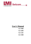
2.4.2 Recommended Connectors
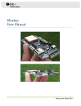
2.4.2.1 Power In / Out
The Input and Output power connectors are identical. They are JST connector part S2B-PH-SM4TB(LF)(SN) (Digikey P/N: 455-1749-1-ND).
There are many mating options for this connector, but an easy method is to purchase pre-crimped /
built mating cables. An example of this is Pololu item 1116
http://www.pololu.com/catalog/product/1116 which is a connector and 14cm wire length. For
reference, a picture of this connector is shown here:
SANDMAN User Manual Rev C.
6
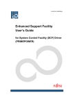
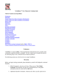
2.4.2.2 Communications Connector (X1)
The communications connector has a set of connections for discrete I/O and communication. This
connector is a 9 pin Molex socket. The mating connector for this is Digi-Key part number WM1727ND, but this is just the connector housing. Pre-crimped wires can be found at Newark, part number
06-66-0013. For reference, a picture of this connector is shown here:
2.4.3 Pin Assignments
Table 1 – Power In/Out Connector Pin Assignments
Pin #
Pin Name
I/O
1
Vin
N/A
Pin
Connection
Required
for Typical
Operation?
X
2
GND
N/A
X
Description
Or Vout if output connector
SANDMAN User Manual Rev C.
7
Table 2 – Communication (X1) Pin Assignments
Pin #
Pin Name
I/O
Pin
Connection
Required
for Typical
Operation?
Description
1
TX
O
2
RX
I
X
3
GND
N/A
X
4
ISP
I
5
DIO1
I
Hold low upon power for reprogramming of unit (not
standard)
TBD
6
DIO2
I
TBD
7
SDA/DIO3
I
TBD
8
SCL/DIO4
I
TBD
9
GND
N/A
UART com from Sandman
3.3V level
UART com to Sandman
3.3V level
Ground
Ground (redundant to pin 3)
SANDMAN User Manual Rev C.
8
3. Hardware Integration
Presented in this section are selected hardware interface comments to help ease integration of the
unit in the end user system.
3.1 Power
3.1.1 Input Power
The module operates off the input power voltage. On board circuitry operates at 3.3V levels.
However, up to 20V may be applied at this connector.
The system draws very little power; typically it will require less than 5 mA of supply for operation
when not in sleep mode.
3.1.2 Output Power
The module outputs the input power voltage when the unit is programmed to allow this output.
When the unit goes to sleep, this output power is turned off.
3.2 Communication Interface
The module utilizes the X1 pins to command the unit and receive status. These pins are described
here.
3.2.1 Pin 1 - TX
Output data from the module.
3.2.2 Pin 2 - RX
Commands to the module
3.2.3 Pin 3 and Pin 9 - Ground
Ground pins for signal use.
3.2.4 Pin 4 - ISP
In system programming pin. Pull low upon boot to load new code via UART.
3.2.5 Pin 5 - DIO1
TBD
3.2.6 Pin 6 – DIO2
TBD
3.2.7 Pin 7 – DIO3
TBD
3.2.8 Pin 8 – DIO4
TBD
SANDMAN User Manual Rev C.
9
3.3 Communication
Sandman has two means of communication - a standard UART and an I2C port.
Currently, the I2C port is inactive, but may be active as a slave device in future software releases.
3.3.1 UART
The UART is a 3.3V level interface. The unit does not use hardware handshaking. It is always 8
bits, no parity, and one stop bit (8-N-1). Do NOT interface with a standard RS-232 port, as the
voltages on that port will damage the unit. An external adapter that uses 3.3V to convert to RS-232
levels can be powered from the onboard 3.3V regulator.
Standard operation is at 115k baud.
3.3.2 I2C Port
The I2C bus will be configured as a master device. Currently, it is not implemented, but future
software revisions may include this.
3.4 Power Status LED
There is one (1) informational LED on the unit. This LED is for test only, and can be disconnected
by cutting the LED trace solder jumper. The LED pulls an extra 0.5 mA at 5V during normal
operation, so cutting this trace is good practice for energy saving purposes.
SANDMAN User Manual Rev C.
10
4. Software Interface
The hardware com interfaces have been described already. Details on software setup and
communication are presented here.
4.1 Basic Message Structure
Input and Output messages from the unit are identical. Both include header and checksum and
other information to protect data integrity and allow easier decoding by the end user.
4.1.1 Message format
Both input and output messages have a defined structure that consists of the following:
(2) header bytes (0xAE 0xAE)
(1) Message length byte
(1) Message ID byte
(xxx) Payload bytes (varies with message)
(1) Checksum byte
The checksum byte is a LRC checksum calculated for the entire message, including header bytes,
length, id, and data bytes. Details and code for calculating this checksum are provided later in this
section.
4.1.2 Number Formats
Much of the data messages use single bytes and unsigned integers, which are typically easy to
understand. A number format list is presented here for clarity on number formats however.
All floating point values are transmitted in IEEE754 single precision.
Table 3 - Number Formats
Abbreviation
Type
U1
I1
X1
U2
I2
X2
U4
L4
Unsigned char
Signed char
Bitfield
Unsigned short integer
Signed short integer
Bitfield
Unsigned long
Signed long
Size
(bytes)
1
1
1
2
2
2
4
4
R4
CH
IEEE 754 Single Precision
ASCII encoded
4
1
Comment
2’s complement
2’s complement
2’s complement
Min/Max
0 … 255
-128 … 127
n/a
0 … 65535
-32768 … 32767
n/a
0…4,294,967,295
-2,147,483,648 …
2,147,483,647
-1*2^127 … 2^127
4.1.3 LRC Checksum Code
The checksum calculated for outgoing messages is an 8 bit Longitudinal Redundancy Check (LRC)
code. C code to compute the entire checksum is shown below.
SANDMAN User Manual Rev C.
11
unsigned char calculateLRC(const unsigned char *buf, unsigned int n)
{
unsigned char checksum = 0;
while(n>0){
checksum += *buf++;
n--;
}
return ((char) -checksum );
}
4.1.4 ACK / NACK Response
A properly formatted message that is accepted by the module will be responded to with an ACK or
NACK message. This message follows the same format as other messages.
4.1.4.1 Useful Code Structures
The following structures are useful for the setting and reading of data from the module.
4.1.4.2 TIME Structure
The following C structure is used for both setting and reading time from the unit. This is 27 bytes.
typedef struct
{
unsigned char hun_sec; //Hundreds of seconds
unsigned char tenth_sec; //Tenths of seconds
unsigned char sec;
//Seconds
unsigned char ten_sec; //Tens of seconds
unsigned char min; //Minutes
unsigned char ten_min; //Tens of minutes
unsigned char st; //Oscillator start bit
unsigned char hour; //Hours
unsigned char ten_hr; //Tens of hours (use with 24 hr time)
unsigned char AMPM; //10 hour AM/PM
unsigned char TIMEFORMAT; //If set, 24 hr time. If cleared, 12 hour time
unsigned char CALSGN; //Calibration sign
unsigned char day; //Day
unsigned char VBATEN; //Vbat enable
unsigned char VBAT; //Vbat switched
unsigned char OSCON; //Oscillator on flag
unsigned char date; //date
unsigned char ten_date; //Tens of date
unsigned char month; //Month
unsigned char ten_month; //Tens of month
unsigned char lp; //leap year
unsigned char year; //year
unsigned char ten_year; //Tens of year
unsigned char CTRL_REG; //control register
unsigned char CALIBRATION; //Should be zero if you ever set this
unsigned char WATCHDOG; //Watchdog register
unsigned char EVENT; //Event detect (unused)
} TimeKeeper_RTC_TypeDef;
4.1.4.3 ALARM Structure
The following C structure is used for both setting and reading alarms on the unit. It is 16 bytes long.
SANDMAN User Manual Rev C.
12
typedef struct
{
unsigned char sec;
//Seconds
unsigned char ten_sec; //Tens of seconds
unsigned char min; //Minutes
unsigned char ten_min; //Tens of minutes
unsigned char hour; //Hours
unsigned char ten_hr; //Tens of hours (use with 24 hr time)
unsigned char AMPM; //10 hour AM/PM
unsigned char TIMEFORMAT; //If set, 24 hr time. If cleared, 12 hour time
unsigned char day; //Day
unsigned char ALMxIF; //Alarm Interrupt flag bit (must be cleared by software)
unsigned char ALMxCx; //Alarm match conditions. 000=seconds, 001 = min, 010 = hrs, 111 = sec, min, hr, day,
date, and month
unsigned char ALMxPIN; //Alarm Output Pin config bit. 0 = IRQ pin. 1 = WDO pin.
unsigned char date; //date
unsigned char ten_date; //Tens of date
unsigned char month; //Month
unsigned char ten_month; //Tens of month
} TimeKeeper_ALARM_TypeDef;
SANDMAN User Manual Rev C.
13
5. Input Message Details
Shown in this section are specific input message requirements and details
5.1 Input Message Summary
The output messages from the unit are shown in this summary table:
Table 4. Sandman Message Input
Name
Ping
Set Time
ID
0x00
0x01
Get Time
Set Alarm
Get Alarm
Store Data Start
0x02
0x03
0x04
0x05
Get Data
GoToSleep
0x06
0x07
EasySleep
0x08
Abort Mode
0x09
Generic Sleep
0x0A
Date Sleep
0x0B
Data Package
0x10
Clear Wakeup Flag
0x11
Description
Communication check
Sets time on unit. Time is lost if power to the
module is removed (i.e. no battery backup)
Retrieves the time from the unit
Sets alarm on unit.
Retrieves the alarm currently set on the unit
Begins store data state. User data may be
stored to NVM on the module in preparation of
power down / sleep
Starts data retrieval from NVM
Goes to sleep, powers down.
Will not engage if alarm time is prior to current
time
Go to sleep for a specified amount of time from
the current time. Does not require user to set
current time, and will occur immediately upon
receipt.
Will stop current mode (store or read data) and
return to normal mode. Should be used to abort
Sandman if there is any possibility that the
communication is suspected to be stalled.
Go to sleep for arbitrary number of seconds,
minutes, hours or days. Only one of these can
be selected (i.e. no combination of seconds,
minutes)
Go to sleep until a specific date and time.
(FUTURE PLANNED MESSAGE, NOT
AVAILABLE CURRENTLY)
Special message containing data to write. The
Store Data Start message has to be sent first
indicating how many data packets are going to
be sent before these will be accepted.
Clears the wakeup flag in the status. This flag is
set when the unit has powered up from a wake
condition to let the user know power went down.
SANDMAN User Manual Rev C.
14
5.1.1 PING (ID 0x00)
Message
Name
PING
0x00
Description
ID
Length
Type
Comment
Input Message
Pings the unit. Unit responds with ping output
message, BIT message, and current time. Useful
for software protocol test.
Message
Structure
Header
0xAE 0xAE
Payload Length
0x01
Byte offset
0
Number format
U1
Scaling
-
Message ID
0x00
Name
N/A
Payload
See Below
Checksum
XSUM
Units
-
Description
Value not used,
but required for
valid message
This message forces a ping output message (0x00) as a response regardless of the package data.
SANDMAN User Manual Rev C.
15
5.1.2 SET TIME (ID 0x01)
Message
Name
Set Time
0x01
Description
ID
Length
Type
Comment
Input Message
Sets the unit time.
Message
Structure
Header
0xAE 0xAE
Payload Length
0x1B
Byte offset
0
Number format
Time Structure
Scaling
-
Message ID
0x01
Name
Current Time
Payload
See Below
Checksum
XSUM
Units
-
Description
Current time from
the unit.
This message sets the time on the unit. This is NOT held in memory if main power is removed to the
module (no battery backup). It is maintained and incremented in deep sleep however.
5.1.3 GET TIME (ID 0x02)
Message
Name
Get Time
0x02
Description
ID
Length
Type
Comment
Input Message
Gets the unit time.
Message
Structure
Header
0xAE 0xAE
Payload Length
0x01
Byte offset
0
Number format
U1
Scaling
-
Message ID
0x02
Name
N/A
Payload
See Below
Checksum
XSUM
Units
-
Description
Requests output
message 0x02
from module
This message requests time from the unit via message 0x02.
SANDMAN User Manual Rev C.
16
5.1.4 SET ALARM (ID 0x03)
Message
Name
Set Alarm
0x03
Description
ID
Length
Type
Comment
Input Message
Sets the unit alarm
Message
Structure
Header
0xAE 0xAE
Payload Length
0x11
Byte offset
0
Number format
Alarm Structure
Scaling
-
Message ID
0x03
Name
Alarm
Payload
See Below
Checksum
XSUM
Units
-
Description
Desired alarm time for
wakeup
This message sets the alarm on the unit. This is NOT held in memory if main power is removed to
the module (no battery backup). It is maintained and incremented in deep sleep however.
Note that the Sandman timekeeping chip only allows these entries for ALMxCx bits in gALARM:
- 000 – Seconds match
- 001 – Minutes match
- 010 – Hours match (logic takes into account 12/24 operations)
- 011 – Day match. Generates interrupt at 12:00:00 AM
- 100 – Date match
- 101 – Unimplemented, do not use
- 110 – Unimplemented, do not use
- 111 – Seconds, Minutes, Hour, Day, Date and Month
Other combinations are invalid and but will not be indicated by a NACK. Recommend use of
message 0x0A for generic sleep if EasySleep values are not acceptable.
Follow this up with the GoToSleep message to power down.
5.1.5 GET ALARM (ID 0x04)
Message
Name
Get Alarm
0x04
Description
ID
Length
Type
Comment
Input Message
Gets the unit time.
Message
Structure
Header
0xAE 0xAE
Payload Length
0x01
Byte offset
0
Number format
U1
Scaling
-
Message ID
0x04
Name
N/A
Payload
See Below
Checksum
XSUM
Units
-
Description
Requests output
message 0x04
from module
This message requests alarm from the unit via message 0x04.
SANDMAN User Manual Rev C.
17
5.1.6 STORE DATA (ID 0x05)
Message
Name
Store Data
0x05
Description
ID
Length
Type
Comment
Input Message
Stores the data for retention during power down
Message
Structure
Header
0xAE 0xAE
Payload Length
0x02
Byte offset
0
Number format
U2
Scaling
-
Message ID
0x05
Name
Bytes to write
Payload
See Below
Checksum
XSUM
Units
-
Description
Number of bytes
to write
(maximum 2944)
After successful receipt of this message, the user is required to send the number of bytes specified
in a stream to the unit. No other operation will occur until all bytes have been received.
This message stores a stream of data to the unit to be saved during power down. All other data on
the unit is erased / overwritten by this message.
5.1.7 GET DATA (ID 0x06)
Message
Name
Get Data
0x06
Description
ID
Length
Type
Comment
Input Message
Requests data retrieval
Message
Structure
Header
0xAE 0xAE
Payload Length
0x02
Byte offset
0
Number format
U2
Scaling
-
Message ID
0x06
Name
Bytes to read
Payload
See Below
Checksum
XSUM
Units
-
Description
Number of bytes
to read via output
message 0x06
This message requests stored data from the unit via message 0x06.
SANDMAN User Manual Rev C.
18
5.1.8 GOTOSLEEP (ID 0x07)
Message
Name
Go To Sleep
0x07
Description
ID
Length
Type
Comment
Input Message
Goes to sleep, wakes on alarm
Message
Structure
Header
0xAE 0xAE
Payload Length
0x02
Byte offset
0
Number format
U2
Scaling
-
Message ID
0x07
Name
Sleep pause
Payload
See Below
Checksum
XSUM
Units
-
Description
Milliseconds to
delay before
going to sleep
This message puts the unit to sleep after the number of milliseconds in the payload.
5.1.9 EASY SLEEP (ID 0x08)
Message
Name
Easy Sleep
0x08
Description
ID
Length
Type
Comment
Input Message
Easy method for setting the unit to sleep
Message
Structure
Header
0xAE 0xAE
Payload Length
0x01
Byte offset
0
Number format
U1
Scaling
-
Message ID
0x08
Name
Type of Easy
Sleep
Payload
See Below
Checksum
XSUM
Units
-
Description
Easy sleep
This message puts the unit to sleep immediately for the specified amount of time.
Type of Easy Sleep:
0 = 10 seconds
1 = 1 minute
2 = 1 hour
3 = 3 hour
4 = 12 hour
5 = 24 hour
SANDMAN User Manual Rev C.
19
5.1.10
ABORT MODE (ID 0x09)
Message
Name
ABORT MODE
0x09
0
Input Message
Aborts the store data / read data modes if in
effect.
Description
ID
Length
Type
Comment
Message
Structure
5.1.11
Header
0xAE 0xAE
Payload Length
0x00
Message ID
0x09
Payload
See Below
Checksum
XSUM
GENERIC SLEEP (ID 0x0A)
Message
Name
Generic Sleep
0x0A
Description
ID
Length
Type
Comment
Input Message
Generic method for setting the unit to sleep
Message
Structure
Header
0xAE 0xAE
Payload Length
0x02
Byte offset
0
Number format
U1
Scaling
-
1
U1
-
Message ID
0x0A
Payload
See Below
Checksum
XSUM
Name
Choice of sleep
Units
-
Time to sleep
Seconds,
Minutes, Hours,
Days
Description
Choice for sleep
(see below)
Actual time to
sleep
This message puts the unit to sleep immediately for the specified amount of time. The first payload
entry represents the choice of sleep units. The following list shows the valid selections:
Choice for sleep units:
0 = seconds
1 = minutes
2 = hours
3 = days (note: triggering on days will wake the unit up at 12:00 a.m. on the next day rollover, NOT
at the current time plus one day)
For example:
To set a 7 hour wakeup, field 0 = 2 and field 1 = 7.
To set a 2 day wakeup, field 0 = 3 and field 2 = 2;
Combinations of 3 hours and 20 minutes are invalid due to timekeeper chip limitations. In a situation
like this, it is recommended to sleep for 3 hours, wakeup and immediately send an additional 20
minute sleep.
This message puts the unit to sleep immediately after receipt, no delay.
SANDMAN User Manual Rev C.
20
5.1.12
DATA PACKAGE (ID 0x10)
Message
Name
Data Package
0x10
64
Input Message
Sends a 64 byte packet of data for storage after
Storage Mode was initiated with message 0x05
Description
ID
Length
Type
Comment
Message
Structure
Header
0xAE 0xAE
Payload Length
0x40
Byte offset
0
Number format
U1
Scaling
-
5.1.13
Name
64 bytes of data
to send
Payload
See Below
Checksum
XSUM
Units
-
Description
64 bytes of data
to send. Keep
sending this
message with
different data
packets until all
data has been
transmitted.
CLEAR WAKEUP FLAG (ID 0x11)
Message
Name
CLEAR WAKEUP FLAG
0x11
0
Input Message
Clears the status flag indicating wakeup.
Description
ID
Length
Type
Comment
Message
Structure
Message ID
0x10
Header
0xAE 0xAE
Payload Length
0x00
Message ID
0x11
Payload
None
Checksum
XSUM
SANDMAN User Manual Rev C.
21
6. Output Message Details
Shown in this section are the specific message descriptions for output messages from the unit.
6.1 Output Messages
The output messages from the unit are shown in this summary table:
Table 5. Sandman Message Output
Name
Ping
Reserved
UNIT TIME
Reserved
UNIT ALARM
Reserved
GET DATA
Reserved
Reserved
ID
0
1
2
3
4
5
6
7
8
Length
4
27
17
Varies
-
Description
“I’m alive” message
Time in module
Alarm in module
Retrieves stored data from module
-
ACK
NACK
0x21
0x63
0
0
Accepted message response
Rejected message response
Note: The length shown in this section is the package / payload length for that message. It does not
include the header characters (0xAEAE), length byte, device ID byte, message ID byte, or checksum
byte.
The messages available with content are follow the same format as the input messages with respect
to header, id, payload and checksum.
SANDMAN User Manual Rev C.
22
6.1.1 PING (ID 0x00)
Message
Name
PING
0x00
Description
ID
Length
Type
Comment
Message
Structure
Output Message
Response to ping request
Header
0xAE 0xAE
Payload
Length
0x04
Message
ID
0x00
Payload
Checksum
0xMM 0xNN 0xPP 0xZZ
XSUM
This message is in response to the 0x00 ping request.
The three bytes sent down (0xMM, 0xNN, and 0xPP) represent the software version on board.
Major.Minor.Revision = MM.NN.PP.
The last byte 0xZZ represents the status of the unit:
0x00 = Unit has powered up and not recovered from a deep sleep event (or deep sleep event
was cleared)
0x01 = Unit has powered up from a deep sleep event
Note that ONLY message 0x11 or a complete power removal from the input will clear this flag.
6.1.2 RESERVED (ID 0x01)
Unused.
6.1.3 UNIT TIME (ID 0x02)
Message
Name
Unit Time
0x02
Description
ID
Length
Type
Comment
Output Message
Time currently residing in the module
Message
Structure
Header
0xAE 0xAE
Payload Length
0x1B
Byte offset
0
Number format
Time Structure
Scaling
-
Message ID
0x02
Name
Current Time
Payload
See Below
Checksum
XSUM
Units
-
Description
Current time from
the unit.
This message is a response to the request time message.
6.1.4 RESERVED (ID 0x03)
Unused.
SANDMAN User Manual Rev C.
23
6.1.5 UNIT ALARM (ID 0x04)
Message
Name
Unit Alarm
0x04
Description
ID
Length
Type
Comment
Output Message
Gets the unit time.
Message
Structure
Header
0xAE 0xAE
Payload Length
0x11
Byte offset
0
Number format
Alarm Structure
-
Name
Alarm
-
16
U1
-
Alarm Type
-
Scaling
Message ID
0x04
Payload
See Below
Units
Checksum
XSUM
Description
Desired alarm time for
wakeup
Alarm type to wake up
on:
Seconds
match
Minutes
match
Hours match
Full date
match
This message is a response to the request alarm message.
6.1.6 RESERVED (ID 0x05)
Unused.
6.1.7 GET DATA (ID 0x06)
Message
Name
Get Data
0x06
0x42
Output Message
Data stored in NVM
Description
ID
Length
Type
Comment
Message
Structure
Header
0xAE 0xAE
Payload Length
0x42
Byte offset
0
Number format
U2
Scaling
-
2
U1
-
Message ID
0x06
Payload
See Below
Checksum
XSUM
Name
Bytes left to
recover
Units
-
Data packet
-
Description
Number of bytes
remaining to
transmit from the
requested
number (count is
not including this
data packet)
64 byte packet of
data requested
(multiple
messages
increment thru
SANDMAN User Manual Rev C.
24
data until “bytes
being recovered’
is finished).
This message is a response to request for stored data from the unit via message 0x06. It will be
output at 100 msec intervals containing 64 bytes of data from the requested data set until all data
has been transmitted.
6.1.8 RESERVED (ID 0x07)
Unused.
6.1.9 RESERVED (ID 0x08)
Unused.
6.1.10
ACK (ID 0x21)
Message
Name
ACK
0x21
0
Output Message
Accepted message
Description
ID
Length
Type
Comment
Message
Structure
Header
0xAE 0xAE
Payload Length
0
Message ID
0x21
Payload
None
Checksum
XSUM
This message is a response to incoming messages indicating that the checksum passed.
6.1.11
NACK (ID 0x63)
Message
Name
NACK
0x63
0
Output Message
Rejected message
Description
ID
Length
Type
Comment
Message
Structure
Header
0xAE 0xAE
Payload Length
0
Message ID
0x63
Payload
None
Checksum
XSUM
This message is a response to incoming messages indicating that the checksum was rejected.
SANDMAN User Manual Rev C.
25
7. Software Reprogramming
The Sandman board can be reprogrammed in the field if necessary. In order to accomplish this, the
user will have to pull down the ISP pin upon powering up. This puts the processor into boot loader
mode, and new firmware can be uploaded via the serial port. Steps to load a new Hex file (firmware
image) into the Sandman board
1)
2)
3)
4)
5)
6)
7)
8)
9)
10)
Download and install the latest version of FlashMagic from this site:
(http://www.flashmagictool.com/)
Power down Sandman
Plug USB node or other USB to serial converter into Sandman
a. See Table 2 for connector details. Port is 3.3V level.
Connect pin 4 (ISP) to pin 3 or pin 9 (GND) on connector X1 (again, see Table 2 for
connector specifics) and KEEP IT CONNECTED FOR THE NEXT STEP!
Power up Sandman
Release ISP to Ground connection from step 4.
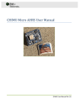
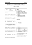
Run FlashMagic and reprogram
a. Open settings file (.fms), or if .fms file is not available, select settings shown below
b. Change COM port to your com port
c. Change path to .hex file to where you stored the hex file to download
d. Press the “start” button, it will flash and verify
e. If it still fails, try powering the unit again as listed above
f. If it still fails, drop the baud rate to 57600
Close FlashMagic
Power board down
Power up without any buttons pressed and verify new code is running
a. This can be done with the serial port connected if you send the ping message:
i. 0xAE 0xAE 0x01 0x00 0x00 0xA3
b. The response will be the status message showing the software major, minor and
revision number (in hex)
SANDMAN User Manual Rev C.
26
8. Software Release Notes
Software version descriptions can be found here.
Table 6 – Software Revision
Major
1
1
Minor
0
1
Build
0
0
Description
Initial release
Added generic sleep support, fixed some bugs
in advanced handling
SANDMAN User Manual Rev C.
27
9. Appendix A: Quick Start Example
The sequence below shows how you can interact with Sandman to store data, turn power off to your
system, and then return power an hour later.
1. Connect hardware correctly (TX/RX to Sandman from host processor, power to entire system
routed thru Sandman)
2. From your microprocessor, send message 0x05 (Store Data) with any data bytes you want to
save in memory while the system
a. After receipt of message 0x05, an ACK response 0x21 will be sent
b. It is the users responsibility to then send the number of bytes specified in message
0x05 to Sandman.
c. This is done using message 0x10.
3. As a check the user can send message 0x06 (Get Data) to retrieve blocks of 64 bytes and
compare to verify the bytes were written correctly.
4. Send message 0x08 (Easy Sleep) with a payload value of “0” to force the unit into a 10
second (demo) sleep mode.
a. The unit will immediately cut power to the system and go into power savings mode
5. When the unit wakes up…
a. User will see the ping message (0x01) from Sandman now indicates that the unit
woke up from a power down event
6. User can recover stored data using message 0x06.
SANDMAN User Manual Rev C.
28