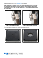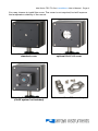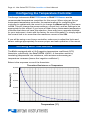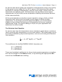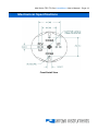
1
Page 2 · 234 Series TEC TO-Can LaserMount User’s Manual Table of Contents Introduction ............................................................................................... 3 Installation and Use................................................................................... 4 Configuring the Temperature Controller ................................................. 10 Working with Thermistors ....................................................................... 10 Connector Pin-Outs ................................................................................ 12 Technical Specifications ......................................................................... 13 Thermal Capacity .................................................................................... 14 Mechanical Specifications ...................................................................... 15 Laser Diode Protection............................................................................ 20 Warranty .................................................................................................. 21 Service and Support ............................................................................... 21 234 Series TEC TO-Can LaserMount User’s Manual · Page 3 Introduction Thank you for choosing the 234 TEC TO-Can LaserMount from Arroyo Instruments. The 234 LaserMount is designed for high performance and long term use. The 234 LaserMount is a higher performance TO-can mount, similar to our smaller 244 LaserMount, but offering a much higher thermal capacity (up to 10W at 25°C), lower operating temperatures, and a much higher 3A higher laser current capacity. The 234 integrates dual Peltier coolers for precise control of the package temperature. With an operating range of -5°C to +85°C, the 234 LaserMount covers a wide range of temperature control needs. The 234 has a cover plate with a small opening whose face is close to the diode as well as mounting holes for 30mm CAGE systems. For applications using 1” lens tubes, there is an optional 234-C-02 cover plate, which replaces the small opening with a larger, 1” threaded opening compatible with 1” lens tube systems. The mount requires no wiring thanks to a simple configuration switches conveniently located on the rear of the fixture. 234 LaserMount is also finned to provide the highest heat dissipation capability, and is designed to be posted mounted (post mount not included). The 234 LaserMount also offers all the features you would expect from a modern TO-Can laser diode fixture, including: Designed to be quickly integrated with Arroyo’s LaserSource and TECSource instruments. Industry-standard D-sub connectors and pin-outs allow for quick integration into existing laser applications. Banana plug for case ground, which can be used as a wrist strap connection or to assure proper grounding to an optical table or test bench. Note: photos in this manual may show a CAGE system or post mount. The 234 does not come with either of these systems; they are shown for illustrative purposes only. Page 4 · 234 Series TEC TO-Can LaserMount User’s Manual Installation and Use Configuring the mount: Start by identifying the specific electrical configuration style of your device from the illustrations below. The switch settings for each style are illustrated on the following page. For two pin devices (style G), which have their pins at the 3 o’clock and 9 o’clock positions, the third switch must be placed in the N/C position. Style A Style B Style C Style D Style E Style G Style H Laser Styles The upper and lower holes of the laser socket, labeled the COM pins, are always tied together. The PD and LD switches on either side of socket are to set the polarity of the outside pin. For example, if your device has the laser cathode common to the photodiode anode (lower left diagram above), when you plug in your device, the left hole would have the photodiode cathode (except for style G lasers, in which case, the left hole is laser cathode), and the right hole would have the laser anode. When installing your laser, the isolated (non-common) photodiode pin goes into the left (PD/LD) hole of the laser socket, and the isolated (non-common) laser pin goes into the right (LD) hole of the laser socket. The common pin can go into either the upper or lower hole. For style G 2-pin packages, the laser anode pin should go into the right (LD) hole of the socket while the laser cathode pin goes into the left (PD/LD) hole of the socket. If you have a 4-pin TO-can package where the laser and photodiode are completely isolated from each other, the mount will connect the two pins that are inserted into the COM positions of the socket. For example, consider the following 4-pin laser configuration: Installed When inserted into the fixture as shown, the laser anode and photodiode cathode pins will be connected together, making the laser equivalent to style A, and the switches should be set accordingly. 234 Series TEC TO-Can LaserMount User’s Manual · Page 5 LD Anode and PD Cathode Common COM Style A (or E) LD LDA PD LDC LD PD/LD PDA N/C PDC PD / LD LD Common Cathode COM Style B (or H) LD LDA PD LDC LD PD/LD PDA N/C PDC PD / LD LD LD Cathode & PD Anode Common COM Style C LD LDA PD LDC LD PD/LD PDA N/C PDC PD / LD LD Common Anode COM Style D LD LDA PD LDC LD PD/LD PDA N/C PDC PD / LD LD 2-Pin Laser Style G LD LDA PD PD/LD PDA N/C LDC LD PD / LD LD PDC » Note the middle (N/C) position of the third switch « Page 6 · 234 Series TEC TO-Can LaserMount User’s Manual Face of 234 with cover off Connect to Laser Diode Driver and TEC Controller: Next, connect the 234 to your laser diode driver and temperature controller. NOTE Arroyo Instruments offers Laser and TEC cables designed to connect directly between our LaserSource and TECSource products. If you use your own cables, ensure the connections are properly made between the instrument and the mount, and that proper grounding techniques are used. The pin-out of the connectors can be found later in this document. WARNING Be sure you are properly ESD protected before handling your laser. For additional information, read the section titled “Laser Diode Protection” later in this manual. 234 Series TEC TO-Can LaserMount User’s Manual · Page 7 Mounting your device: Insert the device so that the common pin is the top or bottom pin, the isolated photodiode pin is on the left, and the isolated laser pin is on the right. If using a 2-pin style G laser, the laser anode would be to the right and the laser cathode to the left. The illustrations below show the mounting of a free-space TO-can laser, but the fiber-pigtailed device would mount in a similar fashion. Your pin length must be in the range of 5mm to 9mm; most diodes are 6.25mm. Longer pins must be trimmed or they will bend when clamping the diode. No Laser Laser Loose Once the device is loaded, for free-space TO-can lasers, use the provided 5.6mm or 9mm diode clamp to clamp the TO-can to the temperature controlled gold plate. For fiber pigtailed lasers, the panel mount holes will line up with either the inside (for 5.6mm) or outside (for 9mm) holes, or the top and bottom holes when mounting vertically housed packages, such as those available from Thorlabs. Clamp, 1 Screw Clamp, 2 Screws Page 8 · 234 Series TEC TO-Can LaserMount User’s Manual When tightening the screws, do not over tighten, which may strip the threads. Do not tighten one side more than the other, as poor or uneven temperature control may result; the two pictures below show a correct and improper use of the diode clamp: GOOD: Diode properly clamped, clip is even with cold plate BAD: Diode improperly clamped, clip is uneven with cold plate The photos below illustrate the various clamps and covers: Standard cover plate Optional 234-C-02 cover plate 234 Series TEC TO-Can LaserMount User’s Manual · Page 9 You may choose to install the cover. The cover is not required, but will improve the temperature stability of the mount. 234 with diode loaded, standard cover 234 with diode loaded, optional 234-C-02 cover 234 with CAGE system attached (CAGE system not included) 5.6mm and 9mm TO-can clamps Page 10 · 234 Series TEC TO-Can LaserMount User’s Manual Configuring the Temperature Controller The Arroyo Instruments 5305 TECSource or 5240 TECSource are the recommended temperature controllers for this mount. When using an Arroyo Instruments temperature controller, the easiest method for configuring the controller to operate with the mount is to change the Mount setting in the menu to 234. This will change the sensor settings, current limit, and fan settings to be appropriate for this mount. If you have an older Arroyo Instruments temperature controller that does not have this selection, there may be an upgrade available for your instrument, check with the factory for more information, or simply adjust the current limit to no more than the maximum current of the 234. If you will be using a non-Arroyo controller, make sure to adjust the limits and sensor settings appropriately to ensure proper and safe operation of the mount. Working with Thermistors The 234 is equipped with a 10kΩ negative temperature coefficient (NTC) thermistor, specifically, the BetaTHERM 10K3A1. A thermistor works by translating temperature into resistance, with resistance decreasing as temperature increases (hence the ‘negative coefficient’). Below is the response curve of the thermistor: Thermistor Resistance vs Temperature Resistance (Ω) 50,000 40,000 30,000 20,000 10,000 0 -10 0 10 20 30 40 50 60 Temperature (°C) 70 80 90 100 234 Series TEC TO-Can LaserMount User’s Manual · Page 11 As can be seen be the graph, the resistance of the thermistor drops very quickly. In the typical control range (0°C to 40°C), typical 10K thermistors offer good sensitivity to changes in temperature, and this is the range in which most 10K thermistors are typically used. 10K thermistors can be used at much higher temperatures, but will suffer poorer temperature stability performance because of the lower sensitivity. All Arroyo temperature controllers support operation using a 10μA or 100μA thermistor bias, which limits the upper control range to 450kΩ or 45kΩ, respectively. To minimize noise and maximize stability, you should select highest current while still allowing you full operation across your required temperature range. The typical setting is 100μA, but your application will determine the actual needs. The Steinhart-Hart Equation As can be seen from the temperature versus resistance graph above, resistance varies inversely with temperature in a non-linear fashion. This relationship can be accurately modeled by polynomial equations, and one such being the SteinhartHart equation: 1 A B * ln( R) C * ln( R) 3 T The coefficients for the BetaTHERM 10K3A1 thermistor are: A = 1.12924x10⁻³ B = 2.34108x10⁻⁴ C = 0.87755x10⁻⁷ These are the default coefficients for Arroyo Instruments temperature controllers, but can be changed in the Sensor menu, or by selecting the appropriate 234 mount from the Mount menu setting. Page 12 · 234 Series TEC TO-Can LaserMount User’s Manual Connector Pin-Outs 234 Rear Connectors DB-9 Pin Description 1–3 No connection 4&5 Laser cathode 6 Photodiode cathode 7 Photodiode anode 8&9 Laser anode Laser DB-9 Connector Pin-Out DB-15 Pin Description 1&2 TE (+) 3&4 TE (-) 7 Thermistor 8 Thermistor 11 FAN (+) 12 FAN (–) 5, 6, 9-15 No connection TEC DB-15 Connector Pin-Out The nitrogen fitting is intended for use with lid-less TO-can applications, or where condensation might occur. The recommended flow rate is 2-3 CFH, or whatever is required to prevent condensation. 234 Series TEC TO-Can LaserMount User’s Manual · Page 13 Technical Specifications FICATIONS 234 TEC TO-Can LaserMount Laser Packages Supported Fiber Pigtailed Package Support Pin Length Range Maximum Laser Current Temperature Control Temperature Range Sensor Type TE Module (at 25°C) Recommended Controller Mechanical Summary 234 Center hole Cage mount Size (H x W x D) [in(mm)] 234 with 234-C-02 Cover Plate Center hole Cage mount Size (H x W x D) [in(mm)] Connectors Laser Diode Mount TEC Nitrogen Case Ground General Fan Power Mounting holes 5.6mm and 9mm TO-Can, 3 & 4 pin Flange mount, 12mm or 18mm horizontal hole spacing, or 0.75” (19.1mm) vertical hole spacing. 5mm to 9mm 3 Amps -5°C to +85°C 10kΩ Thermistor Imax = 5.6A Vmax =7.2V 5305 or 5240 TECSource 1.035”-40, threaded through 4-40 x 4 holes, 30mm on center 3.0 (76.2) x 3.0 (76.2) x 2.91 (73.9) 0.27” [6.9mm], straight through 4-40 x 4 holes, 30mm on center 3.0 (76.2) x 3.0 (76.2) x 3.19 (80.9) DB-9, male DB-15, male 1/16” barb 4mm banana jack 12VDC, 210mA max 8-32 and M4 threaded holes Page 14 · 234 Series TEC TO-Can LaserMount User’s Manual Thermal Capacity The maximum thermal load supported by the 234 depends on the ambient temperature and cold plate temperature, as shown by the graph below. The performance is based on an ambient temperature of 25°C, and actual performance will be improved or degraded if the ambient temperature is lower or higher, respectively. 234 Thermal Capacity (25°C Ambient) Maximum Thermal Load (W) 25.0 20.0 15.0 10.0 5.0 0.0 -10 0 10 20 30 40 50 60 70 Plate Temperature (°C) When operating at temperatures that cause condensation (below the dew point), the fixture must be purged with nitrogen to prevent the condensation of moisture for two reasons: 1. 2. The energy required to condense the moisture from the air will significantly degrade the performance of the fixture; and Condensation can lead to an accumulation of water inside the fixture, which, over time, can cause corrosion and interfere with the proper operation of the mount. 234 Series TEC TO-Can LaserMount User’s Manual · Page 15 v Mechanical Specifications Front Detail View Page 16 · 234 Series TEC TO-Can LaserMount User’s Manual 5.6mm Clip 9mm Clip 234 Series TEC TO-Can LaserMount User’s Manual · Page 17 234 with Standard Cover, Front View 234 with Standard Cover, Side View Page 18 · 234 Series TEC TO-Can LaserMount User’s Manual 234 with 234-C-02 Cover, Front View 234 with 234-C-02 Cover, Side View 234 Series TEC TO-Can LaserMount User’s Manual · Page 19 Bottom View Rear View Page 20 · 234 Series TEC TO-Can LaserMount User’s Manual Laser Diode Protection Electrostatic discharge and current spikes can be a significant cause of damage to laser diodes, but when proper precautions are taken, these risks can be greatly reduced or eliminated. Arroyo Instruments’ controllers offer state-of-art laser diode protection, but no instrument can fully shield the laser from damage. Please take these considerations into account when operating your laser: 1. 2. 3. 4. 5. 6. Always set the current limit at or below the maximum current your laser can handle. This prevents the device from accidentally driving the current too high, either via the set point or from the modulation port. This also provides additional current limiting protection from ESD. Always work in an ESD safe operating environment, including the use of wrist straps, ESD grounded work surfaces and floors, and ESD-safe tools. Where the AC power to the laser driver to temperature controller may be noisy, use isolation transformers or uninterruptible power supplies that provide isolation. Make sure all cables are securely connected and fastening screws are screwed in tight. Do not route power cords or other cables in parallel with the laser or temperature controller cables, as coupling may occur between the cables and inject noise into the laser diode. While it is not possible to create a ground loop through the LaserSource because of it’s isolation of all inputs, it is possible when using other equipment. Ensure that any other equipment is properly isolated to avoid any ground loop problems. 234 Series TEC TO-Can LaserMount User’s Manual · Page 21 Warranty Arroyo Instruments warrants this product to be free from defects in material and workmanship under normal use and service for a period of two (2) years from date of shipment except for the TEC element on fixtures designed for 150°C operation. For 150°C capable fixtures, Arroyo Instruments warrants the Peltier (TEC) element to be free from defects in material and workmanship under normal use and service for a period of one (1) year from date of shipment. This warranty does not apply when the product has been misused, altered or damaged by accident or abnormal conditions of operation. If found to be defective during the warranty period, the product will either be repaired or replaced at Arroyo Instruments's option. THIS WARRANTY IS IN LIEU OF ALL OTHER WARRANTIES, EXPRESSED OR IMPLIED, INCLUDING IMPLIED WARRANTIES OF MERCHANTABILITY OR FITNESS FOR ANY PARTICULAR PURPOSE. ARROYO INSTRUMENTS SHALL NOT BE LIABLE FOR ANY INDIRECT, SPECIAL, OR CONSEQUENTIAL DAMAGES RESULTING FROM THE PURCHASE OR USE OF ITS PRODUCTS. Service and Support For service and support, contact your local distributor or Arroyo Instruments. By mail: By phone: By fax: Email: Web: Arroyo Instruments 624 Clarion Court San Luis Obispo, CA 93401 USA +1 (805) 543-1302 +1 (805) 543-1303 [email protected] http://www.arroyoinstruments.com Page 22 · 234 Series TEC TO-Can LaserMount User’s Manual NOTES: 234 Series TEC TO-Can LaserMount User’s Manual · Page 23 NOTES: Copyright © 2013, Arroyo Instruments, All Rights Reserved 530-1034 Rev B