1
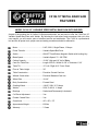
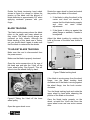
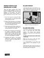
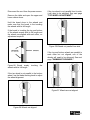
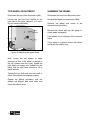
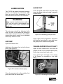
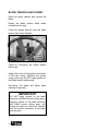
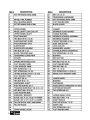
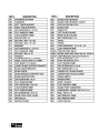
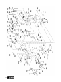
CX106 18" VARIABLE SPEED BAND SAW WITH BLADE WELDER USER MANUAL TABLE OF CONTENTS General Safety Instructions ---------------------------------------------- 3 Specific Safety Instructions ---------------------------------------------- 4 Features ---------------------------------------------------------------------- 5 Physical Features ---------------------------------------------------------- 6 Un-packing ------------------------------------------------------------------- 7 Moving CX106 -------------------------------------------------------------- 7 Setup -------------------------------------------------------------------------- 7 Proper Grounding ---------------------------------------------------------- 8 Assembly --------------------------------------------------------------------- 9 Blade Tensioning and Tracking----------------------------------------- 9 Blade Guide Assembly---------------------------------------------------- 11 Basic Controls--------------------------------------------------------------- 13 Test Run ---------------------------------------------------------------------- 15 Disabling Power to the Band Saw & Welding Station ------------- 16 Work-piece Inspection ---------------------------------------------------- 16 Guide Post ------------------------------------------------------------------- 16 Table Tilt---------------------------------------------------------------------- 17 Premature Blade Breakage & Care------------------------------------ 18 Blade Shear ----------------------------------------------------------------- 18 Blade Welding--------------------------------------------------------------- 18 Maintenance ----------------------------------------------------------------- 21 Cleaning ---------------------------------------------------------------------- 21 V-Belts Replacement ------------------------------------------------------ 21 Tilt Scale Calibration------------------------------------------------------- 22 Wheel Alignment ----------------------------------------------------------- 22 Lubrication ------------------------------------------------------------------- 25 Parts Breakdown and Parts List ---------------------------------------- 27-35 Warranty---------------------------------------------------------------------- 36 2 GENERAL SAFETY INSTRUCTIONS Extreme caution should be used when operating all power tools. Know your power tool, be familiar with its operation, read through the owner’s manual and practice safe usage procedures at all times. ALWAYS read and understand the user manual before operating the machine. DISCONNECT the power source when changing blade and / or making adjustments. CONNECT your machine ONLY to the matched and specific power source. NEVER leave a tool unattended while it is in operation. ALWAYS wear safety glasses respirators, hearing protection and safety shoes, when operating your machine. NEVER reach over the table when the tool is in operation. DO NOT wear loose clothing or jewelry when operating your machine. A SAFE ENVIRONMENT is important. Keep the area free of dust, dirt and other debris in the immediate vicinity of your machine. BE ALERT! DO NOT use prescription or other drugs that may affect your ability or judgment to safely use your machine. ALWAYS keep blades, knives and bits sharpened and properly aligned. ALL OPERATIONS MUST BE performed with the guards in place to ensure safety. ALWAYS use push sticks and feather boards to safely feed your work through the machine. ALWAYS make sure that any tools used for adjustments are removed before operating the machine. 3 CX106 18” METAL BAND SAW SPECIFIC SAFETY INSTRUCTIONS CX106 is designed for cutting metal only. ALWAYS INSPECT the blade for any cracked or missing teeth before operating the band saw. ALWAYS ENSURE that the blade tension is properly set for the type and width of blade installed. NEVER place your fingers or hands in the line of cut. If you slip, your hands or fingers may come into contact with the blade. Always use a push stick when ripping narrow pieces. DO NOT back the work-piece away from the blade while cutting. Always turn off the machine if you are backing out a cut. ALL GAURDS must be in place while operating the band saw to ensure safety. ALWAYS FEED the stock smoothly. Do not force or twist the work-piece while cutting. ALWAYS ENSURE that the band saw blade guard is no more than 1/2” above the stock. MAKE SURE before making any adjustments, the switch is in the “OFF” position and the cord is un-plugged from the power source. NEVER LEAVE the band unattended while it is running. saw DO NOT attempt to remove jammed pieces unless the band saw has come to a complete stop and the power switch has been turned to the OFF position. NEVER TURN ON the band saw if the blade is in contact with your stock. ALWAYS ENSURE that the guide blocks are properly set to prevent blade wander. ALWAYS MAKE CERTAIN that the bearings are properly adjusted to guide the blade. MAINTAIN AND SERVICE your band saw regularly as instructed in the user manual. MAKE SURE you have read and understood all the safety instructions in the manual and you are familiar with your band saw, before operating the CX106. If you fail to do so, serious injury could occur. WARNING! The safety instructions given above can not be complete because the environment in every shop is different. Always consider safety first as it applies to your individual working conditions. 4 CX106 18" METAL BAND SAW FEATURES MODEL CX106 18” VARIABLE SPEED METAL BAND SAW WITH WELDER As part of the growing line of Craftex CX-Series machineries, we are proud to offer the CX106 an 18” Variable Speed Band Saw with Welder. By following the instructions and procedures laid out in this user manual, you will receive years of excellent service and satisfaction. The CX106 is a professional tool and like all power tools, proper care and safety procedures should be adhered to. Motor....................................................2-HP, 220-V, Single Phase, 12 Amps Power Transfer ....................................Variable Speed Belt Drive Switch ..................................................ON/OFF Push Button, Magnetic Switch with Locking Key Blade Speed ........................................Variable Speed; 75 - 385 FPM Cutting Capacity...................................10-3/4" High and 18" Left of Blade Cast Iron Table Size ............................Length 23-5/8" x Width 21-5/8" x Thickness 1-3/4" Table Tilt ..............................................15° Left / Right & 10° Front / Back Floor to Table Height ...........................39” Table Construction...............................Precision Ground Cast Iron Wheels Construction............................Precision Balanced Cast Iron Wheel Size...........................................18-1/4" Body Construction................................Formed Steel Grinding Wheel ....................................1/8-HP, 220V, 0.75 Amps Welder..................................................220V, 2.4KVA, 11 Amps Bearings...............................................Sealed and Permanently Lubricated Co-Planer Adjustment..........................Yes Powder Coated Paint ...........................Yes Overall size ..........................................40" x 30" x 75" Approximate Weight.............................835 lbs Warranty ..............................................3 Years 5 CX106 18” METAL BAND SAW PHYSICAL FEATURES Digital Readout Upper Cabinet Door Guide Post Hand Wheel & Lock Lever Control Panel Work Lamp Blade Shear Air Hose Blade Welding Station Table Grinder Blade Guides Fence Lower Cabinet Door Lifting Eye Bolt Blade Tracking Knob Variable Speed Hand Wheel Blade Tension Hand Wheel Chips Chute Floor Mounting Brackets 6 Motor Access Door UNPACKING The machine is properly packaged in a crate for safe transportation. When unpacking, carefully inspect the crate and ensure that nothing has been damaged during transit. While doing the inventory if you can not find any part, check if the part is already installed on the machine. Band Saw.......................................... Fence ................................................ Fence Lock Knob .............................. Hex Wrench 10mm............................ Hex Wrench 5mm.............................. When the band saw is at the desired position, unbolt it from the pallet. Lift the band saw enough to clear the pallet with a fork truck and remove the pallet. SETUP LIST OF CONTENTS A. B. C. D. E. You can also move the band saw using a pump truck. The band saw comes bolted on a pallet and you can use a pump truck with the band saw bolted on the pallet and move it to the desired position. 1 1 1 1 1 MOVING CX106 The CX106 is provided with an eye bolt which is located on the top of the band saw. The unpainted surface of the machine are coated with a rust preventive and you will want to remove this before you begin assembly. Use a solvent cleaner that will not damage painted surfaces. When setting up your machine, you will want to find an ideal spot where your band saw will most likely be positioned most of the time. Consider your complete work environment before placing your machine in the ideal spot. When moving the band saw, place the lifting hooks through the eye bolt and lift it using a fork truck. See figure-1. Figure-2 Minimum work space for CX106 Figure-1 Lifting the band saw 7 PROPER GROUNDING Grounding provides a path of least resistance for electric current to reduce the risk of electric shock. CX106 is for use on a normal 220 volt circuit. Make sure that the machine is connected to an outlet having the same configuration as the plug. If an adaptor plug is used, it must be attached to the metal screw of the receptacle. To prevent electrical hazards, have a qualified electrician ensure that the line is properly wired. The band saw should be wired with a plug having 3 prongs to fit a 3 prong grounded receptacle as shown in figure-3. Do not remove the grounding prong to fit it into a 2 pronged outlet. Figure-3 220-Volts outlet for CX106 8 WARNING! Improper connection of the equipmentgrounding conductor can result in a risk of electric shock. Check with a qualified electrician if you are in doubt as to whether the outlet is properly grounded. It is strongly recommended not to use extension cords with your CX106. Always try to position your machine close to the power source so that you do not need to use extension cords. In case if you really find it necessary to use an extension cord, make sure the extension cord does not exceed 50-feet in length and the cord is 14-gauge to prevent motor damage. ASSEMBLY TO TENSION THE BLADE: The CX106 band saw comes fully assembled from the factory, except the fence. Make sure the cord is disconnected from the power source. To install the fence, place it on the table and secure it using the lock knob. See figure-3. Figure-3 Installing the fence BLADE TENSIONING AND TRACKING When tensioning the blade, it affects the position of the blade on the wheels. We recommend you to perform blade tensioning and tracking together. Open the upper wheel cover. Raise the upper blade guides to the highest using guide post hand wheel. See figure-4. Figure-4 Guide post and blade tensioning hand wheel Apply moderate pressure using your index finger, midway between the upper blade guides and the table to check the amount of deflection of the blade. See figure-5. TENSIONING THE BLADE A properly tensioned blade is very important to get the best performance from any band saw. If the blade is too loose there is a possibility that the blade slip or drift off the line while operation and it will be hard to have accuracy in the line of cut. If the blade is tensioned too tightly, it will be very difficult to make tighter radius cuts and secondly there will be a great possibility of breaking prematurely. Figure-5 Checking blade deflection The proper amount of blade deflection is approximately 3/8". 9 Rotate the blade tensioning hand wheel shown in figure-4 to release or tighten the tension on the blade until the amount of blade deflection is approximately 3/8" when applying moderate pressure with your finger. BLADE TRACKING The blade tracking means where the blade rides on the upper and lower wheels as they rotate. The blade should always be centered on both wheels. Although the blade tracking of this band saw is factory set, you should check it again to make sure that the blade is centered on the wheels. Rotate the upper wheel by hand and watch the position of the blade on the wheel. If the blade is riding the wheel in the center and does not wander, it means that the blade tracks properly and does not need further adjustments. If the blade is riding up against the wheel flange or wanders, it needs to be adjusted. Adjust the blade tracking by rotating the knob at the rear of the band saw shown in figure-7. TO ADJUST BLADE TRACKING: Make sure the cord is disconnected from the power source. Make sure the blade is properly tensioned. Open the motor access door at the rear of the band saw and take the V-belt off the lower wheel pulley. See figure-6. This will allow to turn the wheels freely by hand. Figure-7 Blade tracking knob If the blade is moving away from the wheel flange, turn the blade tracking knob clockwise and if the blade is moving against the wheel flange, turn the knob counterclockwise. Turn the blade tracking knob and rotate the upper wheel by hand while observing the position of the blade on the wheel. Figure-6 Taking the V-belt off the lower wheel pulley Open the upper wheel cover. 10 Once the blade tracks properly on the wheel, re-install the V-belt and close the upper wheel cover and rear motor access door. BLADE GUIDE ASSEMBLY Properly adjusted support bearings help to keep the blade straight while cutting and play an important role in getting accurate cuts. Now, loosen the blade support adjustment set screw located on the guide post and position the blade support 0.016" behind the blade using a feeler gauge. See figure9. Although the blade guide assembly on CX106 is properly adjusted at the factory but we recommend that you check them. BLADE SUPPORT ADJUSTMENT The blade support is a round rod which is positioned behind the blade to support the blade while cutting. The distance between the blade and the support rod is supposed to be 0.016". See figure-8. TO ADJUST THE BLADE SUPPORT: Make sure the cord is disconnected from the power source. Using a hex screw loosen the blade guide adjustment set screw located on the guide post. See figure-8. Figure-9 Blade guide assembly Once the support rod is at the correct distance from the blade, re-tighten the blade support adjustment set screw. BLADE GUIDE ADJUSTMENT The guides are positioned beside the blade to support the blade from both sides and behind the teeth gullets to prevent the teeth from damage when pushed back while cutting. TO ADJUST THE BLADE GUIDES: Make sure the cord is disconnected from the power source. Before adjusting the blade guides, ensure that the blade support rod is positioned correctly behind the blade. Figure-8 Blade guide assembly Move the blade guide bracket with the blade guides away from the blade. Loosen the blade guide adjustment set screw located on the guide post shown in figure-8. 11 Position the blade guides 1/16” behind the blade teeth gullets as shown in figure-10. Figure-10 Blade guide position behind the teeth gullets Re-tighten the blade guide adjustment screw to secure the guide in position. Now, loosen the two blade guide adjustment screws, located on the blade guides. See figure-11. Use a feeler gauge and adjust the guides 0.004" away from the blade as shown in figure-11. Figure-11 Adjusting the blade guides 0.004" away from the blade Once the guides are at the correct position from the blade, re-tighten the blade guide adjustment screws. 12 BASIC CONTROLS This section describes the basic controls of the CX106. Use the figure and read the descriptions to understand the basic controls of this band saw. Figure-13 Welding controls G. WELDING POWER SWITCH. Enables/disables power to the welder. Figure-12 Band saw controls H. ANNEAL BUTTON. Allows the blade to cool down gradually. A. MAIN POWER SWITCH. Used to enable/disable power to the band saw and the welding station. B. SELECTOR SWITCH. Used to select the band saw or the welding station. C. ON BUTTON. Starts the band saw. D. EMERGENCY STOP BUTTON. Stops the band saw when pushed in. You will have to turn it slightly so that it pops out before turning the band saw ON. E. SPEED DIGITAL READOUT. Displays the speed of the blade in feed per minute when the band saw is ON. F. OVERLOAD SWITCHES. Shuts off power to the band saw when there is an overload. I. CLAMPING PRESSURE KNOB. Applies pressure to the ends of the band saw blade for proper weld. J. SPARK GUARD. Protects operator's eyes from sparks while welding operation. K. GRINDING WHEEL. Used to smoothen the ends of the blade for a flat and clean joint. L. GRINDING WHEEL ON/OFF SWITCH. Starts/Stops the grinding wheel. M. WELDING CLAMPS. Hold the blade while welding operation. N. WELDING BUTTON. Turn the power on to form the weld. 13 O. BLADE SHEAR. Cuts the blade. P. WELDING POWER LIGHT. Turns on when power is enabled to the welder. Q. OVERLOAD SWITCHES. Shuts off power to the welder when there is an overload. Figure-15 Variable speed hand wheel W. VARIABLE SPEED HAND WHEEL. Used to provide blade speed 75 to 385 RPM. Figure-14 Other controls R. GUIDE POST HAND WHEEL WITH LOCK LEVER. Controls the height of the upper blade guides assembly and blade guard. S. WORK LIGHT. Illuminates the work area on the table. T. AIR NOZZEL. Produces air and removes the chips from the cutting area. U. BLADE TENSIONING HAND WHEEL. Used to increase or decrease the amount of tension on the blade. V. BLADE TRACKING KNOB. Used to adjust the blade position on the wheels. 14 TEST RUN Once you have assembled your machine completely, it is then time for a test run to make sure that the machine works properly and is ready for operation. Before doing a test run, make sure the blade is tracking correctly on the wheels. WARNING! Before starting the band saw, make sure that you have read and understood the manual and you are familiar with the functions and safety features on this machine. Failure to do so may cause serious personal injury. TO TEST RUN THE CX106: Remove all the tools and objects used for assembling the machine. Walk around the machine, ensure all nuts, bolts, and screws are tightened and the machine is properly assembled. Connect the cord to the power source and turn the main power switch to ON position. Turn the selector switch to "2" selecting the band saw and push the ON button. See figure-16. The band saw should start smoothly with no or little vibration. With the band saw ON, turn the variable speed hand wheel located below the table. Observe the digits on the digital speed readout. Turning the hand wheel should change the digits on the digital speed readout. Now, push the OFF button and this should turn the band saw off. Now, push the ON button without resetting the OFF button. The band saw should not run until you reset the OFF button. Reset the OFF button and turn the selector switch to "1" to the left, selecting the blade welder. Turn the welding power switch to ON position to enable power to the welder. The welding power light will illuminate. Test the grinding wheel by turning the grinding wheel ON/OFF switch. Turn OFF the welder power switch to disable power to the welder. WARNING! This machine can perform many types of operations which are beyond the scope of this manual and are very dangerous if performed incorrectly. The safety instructions given in this manual can not be complete because the environment in every shop is different. Always consider safety first as it applies to your individual working conditions. Figure- 16 CX106 control panel 15 DISABLING POWER TO THE BAND SAW & TO THE WELDING STATION Some hard metals take a longer time when cutting. These kinds of metals need a different type of blade and lubrication while cutting. The CX106 features a main power switch to disable/enable power to the band saw and to the welding station. Tanks, cylinders, valves that contain gasses or liquids can cause fire, explosion or serious personal injury and damage to the machine. Make sure the main power switch is to the OFF position before connecting the cord to the power source. See figure-17. IMPORTANT Avoid cutting tanks, cylinders and valves that contain gasses or liquids if possible. If you find it really necessary to cut these items, always vent and purge them, before cutting. Sometimes it is not safe to cut magnesium. Cutting magnesium with a dull blade can create enough friction to make the small magnesium chips produce fire. Avoid cutting magnesium If possible. Figure- 17 Disabling the power switch WORKPIECE INSPECTION Before cutting a metal work-piece, inspect it carefully for any defects in the material. GUIDE POST The guide post assembly can be moved up or down above the work-piece. The movement of the guide post is controlled with the hand wheel shown in figure-18. For thin or small metals, the work-piece should be clamped between larger pieces to hold the work-piece tight, when fed against the blade. Some small work-pieces will be damaged if cut on the band saw; instead use; a shear or nibblers for this work. Some round work-pieces like cables, chains etc, which are not stable, if not supported with a vise, should not be cut using a vertical band saw. Figure-18 Guide post and controls 16 To make accurate cuts and to reduce the blade slipping out of position, it is recommended to position the guide post so that the upper blade guides are approximately 1/4" above the work-piece while cutting operation. TO ADJUST THE GUIDE POST: Make sure the cord is disconnected from the power source. Loosen the guide post lock lever on your band saw shown in figure-18 and rotate the hand-wheel to move the guide post assembly up or down. When the guide post assembly is about 1/4" above the workpiece, lock the guide post in place using the lock knob. TABLE TILT Tilt the table using the scale shown in figure-19 as a guide and re-tighten the cap screws. WARNING! After tilting the table, make sure to tighten the cap screws and hex bolts properly before operation. Failure to do so could result in moving of the table while operation and you fingers can come in contact with the blade. TO TILT THE TABLE FRONT TO BACK: Make sure the cord is disconnected from the power source. Loosen the two hex bolts under the table, shown in figure-20. The work table on CX106 can be tilted 15° side to side and 10° front to back when bevel cutting. TO TILT THE TABLE SIDE TO SIDE: Make sure the cord is disconnected from the power source. Loosen the two cap screws under the table, shown in figure-19. Figure-20 Front to back table tilt hex bolts Tilt the table to the desired angle using the scale shown in figure-20 and re-tighten the hex bolts. Figure-19 Side to side table tilt cap screws 17 PREMATURE BLADE BREAKAGE & CARE There are many conditions that cause premature blade breakage but most of the times it is because of the poor care and judgment of the operator. This section describes the most common causes of blade breakage and tells you how to avoid it. BLADE SHEAR Using the blade shear on the CX106 is very easy. Simply position the blade into the shear as shown in figure-21 and pull the handle down to cut off the blade end. 1. One of the causes is leaving the blade tensioned when not using the band saw for a long period of time. 2. Always check the blade for any damage or dull teeth before operating the band saw. Dull teeth produces extra amount of heat and damages the blade. 3. When tensioning the blade, make sure it is not over-tensioned and the blade is tracking centered on the wheels. 4. When using a blade with the wrong pitch for cutting a work-piece, the blade produces extra heat and gets damaged. Always select a blade with the right pitch, set and width for each application and use the right speed for the blade. 5. Sometimes the blade is not properly welded and it breaks when tensioned and used. Always use a blade which is properly welded. Figure-21 Cutting off the blade end BLADE WELDING The CX106 is equipped with a blade welder used to weld band saw blade ends together. The welder uses electrical resistance to head and fuse the blade ends together. TO WELD THE BAND SAW BLADE ENDS TOGETHER: Make sure the motor is OFF and power switch key is in the locked position. It is recommended to use heavy duty leather gloves for the protection of your hands. Grind the blade ends using the grinder on the CX106 to make sure there is no teeth in the welding area. See figure-22 18 Position one of the blade ends evenly into one of the welder clamps so that the teeth of the blade are the facing towards you. Make sure that the blade end is midway between the two welding clamps as shown in figure-24. Turn the clamping pressure knob located on the welder control panel to "0". See figure-25. Figure-22 Grinding the blade teeth off the welding area Figure-25 Welder controls Figure-23 Grinding the blade ends Now, pull the plastic shield up located on the welder and pull the lock levers down to release welding clamps. See figure-24. Now place the second blade end into the welding clamp so that its end is evenly touching the opposite blade end and lock the lever to secure it in position. See figure25. Position the welding shield to its position to guard the welder. Use the table given below for setting the correct clamping pressure according to the width of the blade. Figure-24 Blade into the welding clamps 19 WARNING! Let the blade cool down completely, release the lock levers and check the weld. The flammable material can catch fire from the burning sparks produced during welding. Make sure to keep the welder shield down and do not weld close to the flammable materials. Grind the blade with its both sides so that that weld is smooth. Make sure not to grind the teeth or overheat the blade. This can weaken the weld. Connect the cord to the power outlet and turn the welding power switch knob to the ON position. Press the welding button and release to form the weld. Do not to hold the welding button. Turn the clamping pressure dial to "0" and push the lock levers down to release the welding clamps and check the weld. If the blade is not welded properly and having gaps, go back to the first step and grind the blade to square up the ends. If the blade is welded properly and is even and smooth with no gaps, continue to the next step. Position the blade into the weld clamps with the weld in the center between the two clamps. Press the annealing button two or three times until the weld area turns red but do not hold the annealing button. This will allow the weld to cool down gradually. Repeat the above step four to five times and let the weld for about 35 seconds to cool down each time. 20 Bend the blade in an arc with the weld in the center of the arc and test its strength and flexibility. The blade should bend smoothly with no angles. Turn the welder OFF. MAINTENANCE During the life of your machine, you will need to practice some regular maintenance to keep your band saw in peak performance condition. Clean the wheels and the areas around the wheels after every 20 days or so to make sure that there is no metal chips or built up grease. V-BELTS RELACEMENT WARNING! Make sure the machine’s power switch is OFF and the cord is disconnected from the power source when installing / removing any part or servicing the band saw. Check your machine daily for the following before use: Loose mounting nuts, bolts, and parts Damaged or dull blade Blade tracking Damaged or worn cord Any other unsafe condition The v-belts get old with use and will need to be replaced. TO REPLACE THE V-BELTS: Disconnect the cord from the power source. Open the cabinet door to access the pulleys and the v-belt. Take the belt off from motor pulley and the air pump pulley. Lift the air pump pulley up and to release the tension and remove the belt from the motor pulley and variable speed pulley. Remove the v-belt from the lower pulley and then remove it from the variable speed pulley. See figure-26 Check you machine after every 15 days or so for the following: Damaged or worn V-belt. Air pump lubrication CLEANING The table should be cleaned and wiped after every use to make sure there is no chips and debris. Apply rust preventive product to keep the table rust free. Figure-26 Pulleys and v-belts 21 Install the new v-belts in the reverse order as you removed the old v-belts and close the cabinet door. Check the scale pointer underneath the table. If the scale pointer does not point directly to the 0° mark, loosen the screw and adjust the pointer to 0° mark. Retighten the screw. TILT SCALE CALIBRATION The table tilt scale on your CX106 needs to be calibrated with the blade for accurate cuts. TO CALIBRATE THE TILT SCALE: Disconnect the cord from the power source. Loosen the cap screws (for side to side) and hex bolts (for front to back) tilt scale calibration. Place a square on the table against the blade as shown in figure-27. Do not place it against the teeth of the blade. WHEEL ALIGNMENT The CX106 comes with heavy duty cast iron wheels for added stability and overall performance. When wheels are properly aligned and parallel to each other it will give less vibration, more power, accuracy and less wandering. The wheels on your band saw were properly aligned at the factory but after a long period of time of use the wheels might become out of alignment and will need to be adjusted. The wheels are out of alignment when, the blade does not track properly even after adjustments, excessive vibration while operation and excessive blade wandering when cutting. IMPORTANT Figure-27 Square positioned to check table front to back tilt Wheel alignment is adjusted in very rare cases and is not a simple and common adjustment. Before adjusting the wheel alignment make sure to perform blade tensioning and tracking adjustments to see if the problem is solved with those simple adjustments. TO CHECK WHEEL ALIGNMENT: Adjust the table so that the square is touching the blade with its full length and the table is at 90° with the blade. Retighten the cap screws / hex bolts underneath the table to secure the table in position. 22 You need a 2 x 6 x 5' board with it is one edge completely straight and cut a slot in the middle for the cabinet. This board will work as a gauge that can reach the top and bottom wheels at the same time. See figure-28. Disconnect the cord from the power source. Remove the table and open the upper and lower cabinet doors. If the top wheel is not parallel from its side, it will need to be adjusted. See next page "TOP WHEEL ADJUSTMENT". Hold the board close to the wheels and make sure that the board is the touching the wheels with its full length. If the board is touching the top and bottom of the wheels evenly with its full length and the wheels are aligned with each other, no adjustment required. Figure-30 Wheels not parallel from side If the top and bottom wheels are parallel to each other but not aligned, one of the wheels will need to be shimmed. See next page "SHIMMING THE WHEEL". Figure-28 Board evenly wheels with its full length touching the If the top wheel is not parallel to the bottom wheel, use the blade tracking knob to adjust the wheel alignment. Figure-31 Wheels are not aligned Figure-29 Wheels not aligned 23 TOP WHEEL ADJUSTMENT SHIMMING THE WHEEL Disconnect the cord from the power outlet. Disconnect the cord from the power outlet. Loosen the four hex bolts located on the rear side of the upper cabinet 2 to 3 turns. Do not loosen completely. Uninstall the blade and remove the table. Remove the wheel that needs to be shimmed and add shims. Reinstall the wheel and use the gauge to check wheel coplanarity. If the wheels is not coplanar, add or remove shims. If the wheel is coplanar secure the wheel and close the cabinet door. Figure-32 Adjusting the upper wheel Now, loosen the set screws in equal amounts so that if the wheel is twisted to the left (viewed from the front), thread the right hand set screws out (viewed from the back) and the right hand screws in, all in equal amount. Tighten the hex bolts and use the board to check if the wheels are aligned properly. Repeat the above procedure until the wheels are aligned with each other and close the cabinet doors. 24 LUBRICATION The CX106 has sealed lubricated bearings and do not require any lubrication while there are some other components of the band saw which will need to be lubricated. GUIDE POST Lower the guide post all the way down and clean the guide post rack using a rag with mineral spirits. WARNING! Make sure the machine’s power switch is OFF and the cord is disconnected from the power source when lubrication the band saw. The air pump should be lubricated after every 4 hours of use while the guide post rack, tension lead screw and the variable speed pulley shaft needs to be lubricated after every 85 hours of use. AIR PUMP Figure-34 Lubricating guide post rack Apply a light coat of #2 grease or equivalent and use the hand wheel to raise and lower the guide post to distribute the grease. Open rear cabinet door. Add four to five drops of air tool oil to the air pump. See figure-33. VARIABLE SPEED PULLEY SHAFT Open the rear cabinet door and clean the grease and dirt on the variable speed pulley shaft using mineral spirit and a rag. Use a grease gun and apply 3 to 4 pumps of #2 grease or equivalent to the shaft fitting. Figure-33 Lubrication the air pump Clean the excessive oil on the outside of air pump and close the cabinet door. Figure-35 Lubricating the pulley shaft 25 BLADE TENSION LEAD SCREW Open the upper cabinet and remove the blade. Rotate the blade tension hand wheel clockwise all the way. Clean the grease and dirt from the blade tension lead screw threads. Figure-36 Lubricating the blade tension lead screw Apply a thin coat of #2 grease or equivalent to the lead screw. Distribute the grease using a new rag. DO NOT apply grease on the blade tension sliding ways. Re-tension the blade and adjust blade tracking (if required). IMPORTANT DO NOT apply grease on the table trunnions and blade tension sliding ways. Applying grease on the table trunnions and blade tension sliding ways, will create dirt build ups which will interfere with the smooth movement of the table and the ways. 26 27 28 29 30 31 32 33 34 35 WARRANTY CRAFTEX 3 YEARS LIMITED WARRANTY Craftex warrants every product to be free from defects in materials and agrees to correct such defects where applicable. This warranty covers three years for parts and 90 days for labour (unless specified otherwise), to the original purchaser from the date of purchase but does not apply to malfunctions arising directly or indirectly from misuse, abuse, improper installation or assembly, negligence, accidents, repairs or alterations or lack of maintenance. Proof of purchase is necessary. All warranty claims are subject to inspection of such products or part thereof and Craftex reserves the right to inspect any returned item before a refund or replacement may be issued. This warranty shall not apply to consumable products such as blades, bits, belts, cutters, chisels, punches etceteras. Craftex shall in no event be liable for injuries, accidental or otherwise, death to persons or damage to property or for incidental contingent, special or consequential damages arising from the use of our products. RETURNS, REPAIRS AND REPLACEMENTS To return, repair, or replace a Craftex product, you must visit the appropriate Busy Bee Tools showroom or call 1800-461-BUSY. Craftex is a brand of equipment that is exclusive to Busy Bee Tools. For replacement parts directly from Busy Bee Tools, for this machine, please call 1-800-461-BUSY (2879), and have your credit card and part number handy. 36 All returned merchandise will be subject to a minimum charge of 15% for re-stocking and handling with the following qualifications. Returns must be pre-authorized by us in writing. We do not accept collect shipments. Items returned for warranty purposes must be insured and shipped pre-paid to the nearest warehouse Returns must be accompanied with a copy of your original invoice as proof of purchase. Returns must be in an un-used condition and shipped in their original packaging a letter explaining your reason for the return. Incurred shipping and handling charges are not refundable. Busy Bee will repair or replace the item at our discretion and subject to our inspection. Repaired or replaced items will be returned to you pre-paid by our choice of carriers. Busy Bee reserves the right to refuse reimbursement or repairs or replacement if a third party without our prior authorization has carried out repairs to the item. Repairs made by Busy Bee are warranted for 30 days on parts and labour. Any unforeseen repair charges will be reported to you for acceptance prior to making the repairs. The Busy Bee Parts & Service Departments are fully equipped to do repairs on all products purchased from us with the exception of some products that require the return to their authorized repair depots. A Busy Bee representative will provide you with the necessary information to have this done. For faster service it is advisable to contact the nearest Busy Bee location for parts availability prior to bringing your product in for repairs.