1
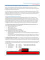
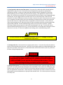
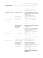
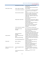
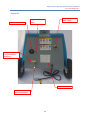
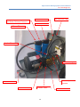
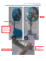
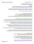
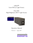
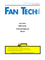
High‐Pressure Misting System Technical Manual Fan Technologies Inc. Fan Tech HMI Series Technical Manual Rev‐B CAUTION Carefully read and understand the entire technical manual before attempting to install, operate, or perform maintenance on this equipment. Contact your supplier if you do not understand these instructions. Failure to follow these instructions may lead to serious injury or death. Retain these instructions for future reference. All operators are to read and understand this manual. 1 High‐Pressure Misting System Technical Manual Fan Technologies Inc. TableofContents Overview of Fan Tech High‐Pressure Misting System ............................................................................. 5 Start‐up and Operation Procedures .............................................................................................................. 5 Permanent Installation ................................................................................................................................. 7 Maintenance ................................................................................................................................................. 8 Troubleshooting ............................................................................................................................................ 9 Replacement Parts ...................................................................................................................................... 11 Consumable/Common Parts ....................................................................................................................... 11 Warranty ..................................................................................................................................................... 12 Appendix ..................................................................................................................................................... 13 3 High‐Pressure Misting System Technical Manual Fan Technologies Inc. OverviewofFanTechHigh‐PressureMistingSystem Thank you for choosing Fan Tech as your provider for high‐pressure misting systems. Fan Tech is devoted to providing its customers with reliable high‐pressure cooling systems engineered with quality components to meet their cooling needs. Fan Tech’s high‐pressure misting system provides superior cooling by combining small orifice misting nozzles with a high pressure pump to create a very fine mist or fog. This fine mist will quickly evaporate reducing the temperature of the ambient air. Fan Tech pairs the misting system with durable fans to reduce the temperature in the desired location. Start‐upandOperationProcedures The high‐pressure misting systems require both electrical and water inputs to function properly. Electrical connections are needed to provide power to the pump motor and the fan motor. Use the proper electrical source to ensure the system will operate correctly. Contact a certified electrician to verify the proper installation if necessary. The water inlet must provide the system with a constant water pressure between 15‐70 psi. A pressure switch has been integrated into the system and will automatically shut down the pump motor if the water pressure is not within the specified range. 1. Connect the water supply to the 3/4” female garden hose adapter on the back of the unit. The water supply should meet the following conditions: Flow rate of 1GPM or more Water less than 7.5 pH Pressure between 15‐75 PSI Dissolved solid content less than 500 PPM Possible damage from improper water supply includes: Clogged misting nozzles or filters due to solids in water. Black or galvanized steel pipe fittings; only use hose and pipe fittings compatible with water to prevent corrosion. Pump damage may occur due to fluctuations in the water supply, cogged nozzle, or closed off discharge side of pump. Never attempt to operate the pump with no water supply connected. 2. Connect the proper power supply. Fan Tech offers a variety of pump and fan combinations which require different amounts of power. Check the list below to see the amount of amps required for each component, amps requirement are also located on the motor plate. Do not use unapproved extension cords or adapters to connect the system. Common electrical systems have plugs only rated to 15 amps. Common breakers are overloaded at 20 amps. Consult a certified electrician if you are unsure about your power supply. 110v 8.8 amps (Models: HMI‐2405 and HMI‐3005) ½ HP Pump Motor: 1 HP Pump Motor: 110v 13.4 amps (Models: HMI‐2410 and HMI‐3010) 24” Fan Motor: 110v 5.9 amps 30” Fan Motor: 110v 9.6 amps WARNING ELECTRICAL SHOCK HAZARD: Serious injury or death is possible Only connect the power supply plug to a properly grounded receptacle. 5 High‐Pressure Misting System Technical Manual Fan Technologies Inc. 3. Initial operation and start up of the system. The pumps for models HMI‐2405 and HMI‐3005 are shipped with a plug in the vent. Remove the sticker along with the plug from the pump before attempting to operate. Pumps for models HMI‐2410 and HMI‐3010 are shipped with a black plug. Before operating remove the black plug and install the red plug. (See appendix for location of the plugs.) All units have been tested by Fan Tech and should be function properly unless shipping damage has occurred. Flip the toggle switch on the back of the unit to activate the pump. Wait for 15‐20 seconds for the motor and pump to activate, the delay is because the water must pressurize the system. If air is trapped in the water supply, press the red knobs on the water filters to relieve the system and open the ball valve on the high pressure side, see appendix for ball valve location. Shortly after the motor and pump begin to run, adjust the pressure knob on the pump so that the pressure gauge reads approximately 1000 PSI. See the troubleshooting section if the system fails to operate. Systems containing multiple misting rings have a ball valve located between the rings. Turn the ball valve to control the water flowing to the inner ring. The mist should form a cone shape when exiting the nozzle. If the cone is not even, or if the nozzle appears to be leaking, see the troubleshooting section. CAUTION Do not increase the system pressure above 1000 PSI. Damage to internal components may occur. 4. Turning on the Fan. Connect the fan to a proper power source. To turn the fan on flip the switch or pull the cord connected to the fan motor. Some fans have multiple speeds or oscillate depending on the type of fan purchased. Place the fan in the desired location and lock the wheels in place to prevent the fan from moving during operation. WARNING ELECTRICAL SHOCK HAZARD: Serious injury or death is possible Only connect the power supply plug to a properly grounded receptacle. PINCH HAZZARD: Do not operate fans without gaurds in place. Do not insert anything into fan guard while the fan is operation. 5. Turning off the system. Turn off the pump and the fan by flipping their respective toggle switches or pull cords. The nozzles should stop emitting the mist immediately. If the nozzles are still dripping, high pressure water may still be in the line and can be relieved by opening the ball valve on the back of the unit, see appendix for exact location. When the power to the pump is shut off the solenoid valve closes, keeping water pressurized between the pump and the solenoid valve. This is done to prevent the pump from a dry start. 6 High‐Pressure Misting System Technical Manual Fan Technologies Inc. PermanentInstallation Systems may be permanently installed by using different types of mounts. The customer is responsible for the installation of fans and pumps. Please consult professionals when installing to ensure of proper compliance with local and state laws. CAUTION Fan Tech is not responsible for Installation. Harm and damage may occur during or due to an improper installation. Please consult a professional when installing. 7 High‐Pressure Misting System Technical Manual Fan Technologies Inc. Maintenance 1. Nozzles. Nozzles should be checked regularly to ensure the best misting performance. The mist or fog should emit from the nozzle in an even cone shape. If the mist is not an even cone shape the nozzle needs to be cleaned or replaced. To clean a nozzle, first remove it from the misting ring. Disassemble the nozzle and soak the nozzle tip and impeller in ZEP, CLR, or vinegar. Do not soak the spring or the body of the nozzle. After soaking, rinse with water and reattach to the misting ring, do not use tools. The nozzles should function properly when screwed in by hand. 2. Pump. The pump requires an initial oil change after 50 hours of service, and additional oil changes every 3 months or 500 hours. Use 8.5 oz of ISO68 hydraulic oil. The oil level can be checked by reading the site glass at the end of the pump, use mirror if necessary. The oil level should be maintained so that it is touching the red dot on the center of the site glass. When changing the oil disconnect the electricity to the system. Do not run the pump without oil in the crankcase. Check the seals and valves for wear after 1000 hours. Check immediately if the systems performance decreases. 3. Filters. The filters should be checked frequently and replaced if needed. The filter life depends on the water source. If the filter is dirty replace immediately because it is restricting water flow to the pump and may damage the system. To check the filter simply unscrew the housing from the top bracket. When replacing the filter it is also good practice to clean the housing with bleach. Use a few tablespoons of bleach mixed with water and scrub the inside of the housing. Make sure the o‐ring is in place when reattaching the housing to the bracket, then hand tighten and check for leaks. 4. Storage. When storing the system for more than a few days or transporting the system, it is important to drain the water. Draining the water prevents calcification problems or the formation of algae. Drain the system by opening the ball valve and relieving the pressure in the system. It may be necessary to tilt the system to drain all the water. Also drain the filter housing to preserve the filter. When transporting the unit, do not tilt or lay flat because the oil may leak out of the pump. Store the unit in a dry location with ambient temperature. Avoid areas that are subject to excessive heat, dust, humidity, freezing, or damage from nearby equipment. If freezing conditions are possible flush your pump with a 50/50 solution of anti‐freeze/water. Also drain any supply hoses or tanks. For initial operation after a long duration of non‐use it is necessary to flush the system of particles. Remove the nozzles from the nozzle rings and place the system in a water safe environment. Power up the system and allow water to flow through the nozzle opening for a few seconds. After flushing the system, reattach the nozzles and tightening by hand. 8 High‐Pressure Misting System Technical Manual Fan Technologies Inc. Troubleshooting Problem Fan will not run. Potential Cause Power supply Connections Misting rings will not mist. Manifold line attached. Pump not operational. Only one ring mists. Pump malfunction. Single stage operation. Surfaces get wet. Mist is too close. Optimum evaporation occurs at least 10 ft. from the fan. Too much mist being produced for the environment. Nozzle leaks during operation. Pump will not run. Use the low speed setting on the fan. Use the ball valve to adjust for singe stage mist ring use only. Plug additional nozzles while maintaining the minimum required for safe pump use. Minimum is 4 nozzles. Use regulator valve to adjust pressure to 1000 PSI. Nozzles are clogged. Remove debris from nozzle tip by cleaning. Nozzles are loose. Turn off the system and relieve pressure to the mist rings, and then hand ‐tighten nozzles. Nozzle o‐ring is worn. Check ball in anti‐drip body for debris and replace if necessary Ant‐drip parts may be worn. Elongate spring or replace nozzle. Power cord is unplugged. Plug in power supply to pump. Power supply is OFF. Turn ON supply power to pump. Water supply is OFF. Turn ON supply water to pump. Circuit breaker OFF. Confirm correct voltage and amperage is being supplied. Inlet pressure is low. Confirm the supply water has a pressure between 15‐70 PSI. Check electrical connection at the pressure switch. Inspect filter. Replace dirty filter which restrict flow. 9 Corrective Action Confirm the control switch and/or pull chain are in the ON position. Confirm the power cords are connected. Confirm that the power supply is on. Confirm the fittings are securely attached at the inline ball valve assembly as well as at the pump cart. Confirm it has a water supply. Confirm control switch is in the ON position. Review pump troubleshooting guide. Turn the ball valve to engage the second stage mist ring. Relocate the fan. High‐Pressure Misting System Technical Manual Fan Technologies Inc. Pump stops running. Pump chatters. Pump leaks. Pump is on but no mist is produced. Solenoid valve is not open. Check electrical connection at the solenoid valve. Check diaphragm of the solenoid valve. Power supply interrupted. Restore power. Circuit breaker switched off. Confirm breaker is no being overloaded or is not worn. Re‐size or replace if faulty. Pressure switch activated. Confirm the supply water has a pressure between 15‐70 PSI. A shared water supply may decrease water pressure. Inspect filter. Replace dirty filter which restrict flow. Check electrical connection at the pressure switch. Pump motor overheated. Never operate the pump above 1000 PSI. Confirm proper ventilation is available to the pump motor. Confirm voltage and that the motor is within the service factor. Pressure switch is turning on and off. Supply water pressure should be consistent. Circuit interrupter is tripped. Press reset button on pump motor. Pump motor may be Motor bearing may have caused pump to seize. Have service shop inspect and damaged. replace if necessary. Motor may have shorted or been overloaded. Have a service shop inspect. Pump head may be Crank bearing/connecting rods may be damaged. damaged. Have a service shop inspect. Pump is being starved of Insure that correct inlet water pressure is supplied, especially at system start‐up. water. Broken or worn bearing. Have service shop inspect and replace if necessary. Stuck inlet/discharge valves. Have service shop inspect valves and replace if necessary. Water is leaking. Have service shop inspect seals and replace if necessary. Tighten filler cap and drain plug. Fill Oil is leaking. crankcase to specified capacity. Have service shop inspect seals and replace if necessary. Pressure regulator turned Turn pressure regulator clockwise to low. increase the pressure. Do not exceed 1000psi. There may be a leak in the Confirm that nozzles are intact. system. 10 High‐Pressure Misting System Technical Manual Fan Technologies Inc. There may be an air‐lock The pump's pressurization components may be damaged. Anti‐drip not functioning. Water sprays from nozzles after system is shut down. Filter housing leaks. O‐Ring failure. Check for loose hose fitting in manifold line. Open the purge valve to release any air‐ lock. This is true if the pump makes a clicking sound. The pump head can be rebuilt, have a service shop inspect. Check integrity of anti‐drip ball and spring. Inspect placement and integrity of o‐ring. Replace if necessary. ReplacementParts Please contact Fan Technologies for the repair drawing packet. Consumable/CommonParts Solenoid Repair Kit Misting Nozzle 10 Micron Filter 5 Micron Filter Hydraulic Oil F02‐04‐003 F01‐06‐001 F06‐02‐002 F06‐02‐001 F02‐06‐001 11 FAN TECH ONE (1) YEAR LIMITED WARRANTY All Fan Tech products are warranted for a period of one (1) year for defects in workmanship and materials under normal use and service. This warranty is extended solely to the original purchaser. In order to initiate this warranty, the Product Registration Form must be completed and sent to Fan Tech, along with a copy of the purchase invoice, within 30 days of purchase. In General: If a Fan Tech product fails because of defect in material or workmanship under normal use and maintenance within one year from date of purchase, we will, at our option and after inspection, repair or replace the defective product. About your Warranty: Fan products, like all mechanical devices, need periodic parts and service to perform well. Normal use and service means not to operate in excess of recommended maximum speeds, pressures, temperatures or using fluids not recommended or compatible with component materials. This warranty does not apply to any component which has been repaired or altered to affect the performance or reliability of the product. Similarly, the warranty is void if the manufacture date or the serial number has been removed or if the equipment has been altered or modified. Fan Tech does not warranty components due to normal wear including nozzles, pumps, motors, and seals. Fan Tech does not warranty components due to misuse, abuse, neglect or improper maintenance, shipping, handling, warehousing or improper installation. This warranty excludes wear items such as water filters, spray nozzles, or pumps that have been run without water supplied; damage or malfunctions resulting from accidents, abuse, modifications, alterations, or improper servicing or freezing or chemical deteriorations. This warranty excludes failures due to acts of God and other force majeure events beyond the manufacturer’s control. This warranty does not cover normal maintenance such as oil changes, water filters, adjustments, or cleaning, etc. This warranty does not cover damage from lack of maintenance (lack of oil or water filter changes) freezing, and obstruction (due to scale, lime, dirt, chemicals, etc.) Fan Tech is not responsible for the removal and shipping of the system to Fan tech, the reinstallation of the product upon its return to the customer, or any incidental or consequential damages resulting from the defect, removal, reinstallation, or shipment of the product. Claims: All warranty claims must be submitted to Fan Tech prior to the expiration of the warranty period. Fan Tech will repair or replace any part of the fan product that is defective in material or workmanship. In order to initiate this warranty, the Product Registration Form must be completed and sent to Fan Tech, along with copy of original purchase invoice, within 30 days of purchase. Transportation charges on the product submitted for warranty must be borne by the purchaser. For warranty service, call Fan Tech for a Return Goods Authorization (RGA) number. Products shipped collect or without an RGA number will not be accepted. If Fan Tech determines that the problem with the product is not due to defects in workmanship or materials, the customer will be responsible for the cost of any repairs and any freight expense to return the product to the customer. If the product is covered by this manufacturer’s warranty, then Fan Tech will pay the freight to send the product back to the customer within the 48 continental United States ONLY. No Other Warranties and Liability Limitation: This limited Warranty and Policy represents Fan Tech’s sole and exclusive warranty obligation with respect to Fan Tech products. Fan Tech’s liability to a customer or any other person shall not exceed the purchase price of the Fan Tech product. Fan Tech disclaims all other expressed and implied Warranties including the implied Warranties of fitness for a particular purpose and merchantability. There is no other express warranty. Any and all implied warranties are excluded. Liability for incidental or consequential damages are excluded to the extent exclusion is permitted by law. This warranty gives you specific legal rights and you may also have other rights which vary from state to state and country to country. High‐Pressure Misting System Technical Manual Fan Technologies Inc. Appendix Hour Meter Toggle Switch for Pump Garden Hose Water Input Tee with Caps For Connecting Satellites Maintenance Chart Ball Valve for relieving pressure 13 High‐Pressure Misting System Technical Manual Fan Technologies Inc. Water Filters Red Button Relieves Pressure Hose to Fan Fan Electrical Plug 10 Micron Filter 5 Micron Filter Cap for Oil Pressure Gauge Wheel Lock Pressure Switch Solenoid Valve 14 Knob to Adjust Pressure Serial Number High‐Pressure Misting System Technical Manual Fan Technologies Inc. Ball Valve Handles are only to be used to push the unit. Do not lift or press down on the handles or they will bend. Connection for adding another satellite unit. Hose from Pump Unit 15 High‐Pressure Misting System Technical Manual Fan Technologies Inc. Fan Technologies Inc. PO Box 1776 Cedar Park, TX 76813 By: D. Kowal Date: 6/10/2013 16