1
MPC5510EVB User Manual Rev 1.0
Sept 2007
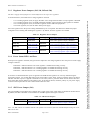
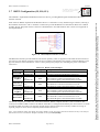
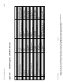
3.1.6.1 VDDE[1..3] Voltage Groupings
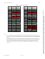
Table 3-4 VDDE[1..3] Pad Groupings
Item
LED Dot Matrix Display
External Memory
CANA and CANC
SCI / LIN A and B
Flexray
JTAG
Nexus
3.1.7
Port Pins
PortC[0..11]
PortG[0..15],
PortF[0..15],
PortH[14,15],
PortJ[0..7]
PortD [0..5]
PortD[6..9]
PortC[0..2, 7..9]
PF[0..11]
VDDE Group
VDDE1
VDDE2
VDDE2 / 3
VDDE2
VDDE2
VDDE1
VDDE1
VDDE1
VDDE3
VDDE2 / 3
Required Pad Voltage
5.0V or 3.3V
5.0V
5.0V
5.0V
5.0V or 3.3V (J18 selects)
5.0V
5.0V
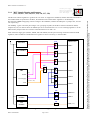
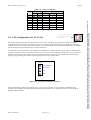
EVB Circuitry Power Domains
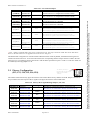
Before disabling any of the EVB regulators, it is worthwhile considering if any of the EVB components or peripherals
you require will be affected. Table 3-5 details a list of the various EVB components and peripherals powered by the
regulators. Note – the SBC powers the MCU only and does not supply power to any of the EVB circuitry.
Table 3-5 Power Supply Distribution
Regulator
1.5V
(Switcher)
3.3V
(Switcher)
5.0V
(Switcher)
5.0V
(Linear)
MPC5510EVBUM/D
Used On
MCU VDD1.5 pins (ONLY use when on-chip MCU regulator is disabled)
Daughter Card Connectors (1.5V)
1.5V Power section of Prototype area
MCU VDD33 and VDDSYN pins (ONLY use when on-chip MCU regulator is disabled)
MCU VDDEx pins (when run in 3.3v mode)
Oscillator Module (Y1)
GAL22V10 (EIM Control)
Driver chip for LED Matrix
I/O supply for Flexray interface when VIO is 3.3V
Daughter Card Connectors (3.3V)
3.3V Power section of Prototype area
MCU VDDEx (5v mode), VPP and VDDR pins
LVI circuit main power (affecting Reset Switch)
Reset-In / Reset-Out logic
Reset configuration circuitry
SRAM memory and address latches
RS-232 Transceiver
LIN transceiver
CAN transceivers
Flexray transceivers
EIM signal pullup resistors
Daughter Card Connectors (5.0V)
5.0V Power section of Prototype area
eICE and Nexus connectors
MCU VDDA pin
LVI circuit monitor
Page 8 of 36
Because of an order from the United States International Trade Commission, BGA-packaged product lines and part numbers indicated here currently are not
available from Freescale for import or sale in the United States prior to September 2010: MPC551x products in 208 MAPBGA package
Before changing the VDDEx voltage from the default 5.0V setting, you need to ensure that this will not impact any of the
EVB peripherals that may be in use. The table below details what EVB peripherals are tied to a particular VDDEx
grouping and also the MCU pin operating voltage suitable for that peripheral.