1
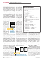
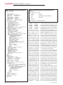
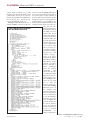
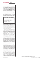
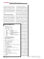
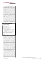
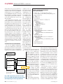
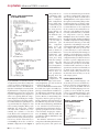
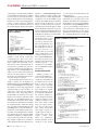
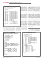
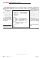
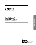
designfeature By Subbu Meiyappan and James Steele, VLSI Technology
THE USE OF ADVANCED VHDL CONSTRUCTS CAN GREATLY
ENHANCE MODELING EFFICIENCY. LEARN HOW TO EFFECTIVELY USE VHDL FOR DYNAMIC-MEMORY ALLOCATION,
HIERARCHICAL TESTBENCHES, AND CREATING FOREIGNLANGUAGE INTERFACES FOR BEHAVIORAL MODELING.
VHDL constructs and
methodologies for advanceddesign verification
he need to model memory is common in any
LISTING 1—SIMPLE MEMORY MODEL USING STATIC ALLOCATION
verification environment. The simplest way to
model memory is to employ static allocation
techniques using array data types. For example, to
model a width-times-depth-sized memory, you use
a construct similar to the one shown in Listing 1.
For small memories, static-allocation techniques
are the simplest to read, understand, and implement.
The static-allocation method allocates the required Gbytes of memory. Even if you allocate all 4 Gbytes,
memory before the program accesses memory—in each simulation run typically hits 10% or less of the
other words, when the simulator starts up (at zero memory space, although these accesses can be ransimulation time). This method has some inherent dom. In other words, it is typical for a simulation to
drawbacks: Every bit of allocated memory corre- toggle all the address bits but not access every byte
sponds to several bits of physical memory; thus, sim- of memory. Because static-allocation techniques for
ulator performance is limited for large memories.
such deep memories greatly limit simulation perConsider a processor with a 32-bit-wide address formance, you should use methods to model membus. Theoretically, the processor can access 4 Gbytes ory efficiently such that the program allocates it in
of memory. If you assume, while simulating the an “on-demand” basis using dynamic-allocation
model of this processor, that every bit of allocated techniques. With dynamic allocation, the program
memory corresponds to 1 bit of physical memory, allocates physical memory on demand on the host
then a static-allocation scheme that allocates all of machine as the model simulates new transactions.
this memory requires about 4 Gbytes of RAM (In a
The approach described in this article is one of the
real case, every bit of allocated memory corresponds classic methods that developers have used for comto several times that
putational problems that use
amount.) If the required
data structures with staticalADDRESS
ADDRESS
ADDRESS
RAM is unavailable, the proly nondeterministic depths.
DATA
DATA
DATA
gram translates the memory
You usually solve such probaccesses into disk accesses, selems by implementing linked
Nxt_Ptr
Nxt_Ptr
NULL
verely slowing a simulation
lists that a program creates
run. On a statistical
and builds dynamically on
Figure 1
This flow chart demonstrates a
note, no single typical
demand. On-demand cresimulation run requires all 4 linked-list organization for a memory model.
ation of a linked list of data
T
www.ednmag.com
November 2 4, 1999 | edn 65
designfeature Advanced VHDL constructs
structures and allocation of new memo- dress. If it finds an adLISTING 2—VHDL PACKAGE CONTAINING
ry locations relies heavily on dynamic- dress match, the proMEMORY PROTOTYPES AND PRIMITIVES
memory allocation and pointer-manip- gram returns the data
ulation techniques. VHDL, using access in the node correspondata types, provides a mechanism to al- ding to that address.
locate new memory locations on demand The program stores
along with pointer arithmetic to manip- each node as a record
ulate the pointers. References 1 and 2 de- data type that it creates
tail dynamic-memory allocation using dynamically on deaccess data types and linked lists. De- mand. The Nxt_Ptr
signers use an application of access data must be of an access
types to dynamically create linked lists type the program uses
for efficient memory modeling. Note that to point to the next
the access data types are nonsynthesiz- node. A first attempt to
able VHDL constructs, so you can use write the type declarathem only for simulations.
tions for this structure
Listings 2 and 3 illustrate the imple- might look like the
mentation of a complete VHDL package code in Listing 4.
for sparsely allocatListing 4 shows
ed memories. This
that the definition of
Addr0
Data0
Addr1
Data1
method of modelmem_entry uses the
Addr2
Data2
ing memory is
type entry_ptr as the
.
.
efficient in randomdata type of one of its
.
.
.
.
simulation environelements but does not
AddrN
DataN
ments in which the
declare entry_ptr unprogram randomly
til after the definition
From a
accesses
of mem_entry. To
Figure 2
user’s permemory.
solve this “chicken-orListing 2 is the spective, the flow
the-egg”
problem,
VHDL description chart in Figure 1
Listing 2 shows the
of the package that looks like a contiguincomplete-type decencompasses the ously located RAM.
laration in line 10; lines 11 through 16
The use of the num_entries in the head
primitives and procreate some type definitions for the pointer is to provide hooks for creating
totypes for creating such a memory. List- linked-list data structure. The Mem_en- a searchable linked list using an algoing 3 is the VHDL description of the try record contains the location, the data, rithm, such as binary sort. The binarypackage body that implements this and the pointer to the next node in the sort algorithm can benefit from knowing
memory. The example is split between list.
the number of entries in a list. You
two listings to simplify the underlying
The idea behind linked lists is to keep arrange the linked list as a linear-data
details of the descriptions. To understand track of the pointers. You need to create structure, in which the physical values of
these details, you should have a basic a pointer that keeps track of the top of the addresses in the linked list are in asknowledge of VHDL; the article explains the linked list, so that you can traverse the cending order. For example, if you allothese details with references to line num- tree from that location. To do this task, cate three locations in memory—
bers in the code.
you create head_ptr in lines 19 through 0x0011, 0x0F00, and 0xFFFF—the first
Figure 1 demonstrates how to organ- 22 (Figure 3). Head_ptr always points to address in the list is 0x0011, and the last
ize the linked list for the memory. Every the topmost node in the list. The Nxt_Ptr address in the list is 0xFFFF. Throughout
node in the list contains an address, a in the last node list is a null pointer that this article, memory is organized to hold
data item to store, and a pointer to the indicates the end of the list.
16 bits of data for each address.
next node in the linked list. From a
Listing 3 defines the mem_pkg packuser’s perspective, this memory looks
age. The body of the package contains the
ADDRESS
ADDRESS
like a contiguously located RAM (Figimplementations for the wr_data and
Num_entr
DATA
DATA
ure 2).
rd_data procedures. The wr_data proceList_Ptr
Every time the program accesses a
dure accepts the address (location), the
Nxt_Ptr
NULL
new address during write operations, it
data to be stored in that address, and the
Head_ptr
Mem_entry
Mem_entry
creates a new node with the address,
pointer to the head of the linked list. Five
data, and a pointer to the next node
scenarios exist in which a write to memFigure 3
in the linked list. During read operory can occur. Assume that a memory
ations, the program traverses the list, try- This two-node linked-data structure shows
write to the following locations in the foling to match the corresponding read ad- how you keep track of pointers in a linked list.
lowing order takes place:
66 edn | November 2 4, 1999
www.ednmag.com
designfeature Advanced VHDL constructs
LISTING 3—VHDL PACKAGE DESCRIPTION IMPLEMENTING
MEMORY OF LISTING 2
LISTING 4—DEFINING MEM_ENTRYWITH AN UNDECLARED DATA TYPE
ENTRY_PTR
Address
Data
0x0F00
0xAAAA
0x0011
0xBBBB
0x0F00
0xCCCC
0x0200
0xDDDD
0x1FFF
0xEEEE
The first time the routine writes into memory,
the program sets the
pointer such that the program allocates only one
memory location. The
nxt_pointer points to a null
location. The program allocates address 0x0F00
with data 0xAAAA. The
code in lines 15 through 21
illustrates this situation.
The next situation involves
a memory location that the
program accesses such that
the address of the requested memory is less than the
value of the address in the
first node of the linked list.
In this case, the program
inserts this new requested
location at the top of the
list. For example, the address 0x0011 is less than
the address 0x0F00, so the
program inserts it at the
topmost node in the list.
The code in lines 24
through 31 illustrates this
scenario. To write to a previously allocated memory
location, the program
overwrites previously written memory. A write to location 0x0F00 overwrites
the data 0xAAAA with
data 0xCCCC without any
further allocation. The
code in lines 35 through 38
performs this operation. A
fourth scenario is a writeto-memory
location
68 edn | November 2 4, 1999
whose physical memory address is between the address in the element in the
top of the list and the address in the last
element in the list. For example, if the
program has allocated addresses 0x0011
and 0x0F00 and receives a request for an
allocation to address 0x0200, the program should insert this node between the
0x0011 and 0x0F00 elements in the list
(lines 39 through 51). The last case is a
write to a memory location whose physical address is greater than the address in
the last element of the list. In this case,
the program appends the newly allocated location to the list, and it becomes the
last element of the list. If the program allocates addresses 0x0011, 0x0200, and
0x0F00 and you request a write to address 0x1FFF, the node corresponding to
the address 0x01FFF is appended to the
list as the last element and its Nxt_Ptr is
set to null (lines 55 through 62).
The rd_data procedure is much simpler because it returns only the data that
the program has already written in allocated locations. The rd_data procedure
accepts the address (location) of the data
that the program needs to read, a storage variable for the data (data) the program will return, a flag (allocated) to indicate whether the program allocated the
requested address by a previous write,
and the pointer to the head of the linked
list. Listing 3 shows the implementation
of the rd_data procedure.
The rd_data procedure walks through
the allocated pointers (until it reaches a
null pointer). The procedure compares
the address of the location with each address in the linked list. If the program
finds a match, the program returns the
data corresponding to that address (Listing 3, lines 80 through 90). A null pointer indicates the end of the list. If the program has not allocated the location,it
returns an “unknown” value (std_logic
U) (lines 92 through 94). In line 88, a
copy of first.list_ptr, starting from the
www.ednmag.com
designfeature Advanced VHDL constructs
current head_ptr, allows you to walk
through to the end of the list until you hit
a null pointer. If you do not copy the
first.list_ptr and make the assignment in
line 82 first.list_ptr = first.list_ptr.nxt,
you are modifying the head_ptr.
Listings 2 and 3 illustrate the use of
advanced VHDL constructs to allocate
LISTING 5—MEMORY-PACKAGE DESCRIPTION
FOR A LARGE-MEMORY APPLICATION
memory on the fly. Listing 5 illustrates
the use of such a package for an application that requires a large amount of
memory. This testbench verifies and illustrates the operation of mem_pkg by allocating memory corresponding to random locations in physical memory and
reading them back. The procedure display_read_data displays two parameters,
loc and data, to stdout
according to the following rule: If any
values other than 0 or
1 in dat correspond to
unknown values, the
program prints them
as binary values; otherwise, it prints them
as hex values. This
rule is necessary because the hwrite function in line 31 defines
std_logic_misc and
converts std_logic_
vector to bit_vector,
losing all the MultiValued Logic (MVL9)
information. Other
efficient procedures
that are internal to
VLSI
Technology
print dat without
performing
such
checks. For the sake
of completeness, Listing 5 shows the procedure display_read_
data. Listing 5 also
shows the test VLSI
uses to verify the
memory. Some procedure calls in Listing
5 illustrate the use of
the variables and
constants in the calls.
Lines 75 through 76
show a common way
to stop the simulator
after the test is complete. Compiling the
previous model puts
the lowest memory
access at location 0
and the last memory
access at location
0x7FFFFFFF
(=2
Gbytes). Static allocaCircle 3 or visit www.ednmag.com/infoaccess.asp
www.ednmag.com
November 2 4, 1999 | edn 71
designfeature VHDL
tion needs 2 Gbytes of storage, which
causes a significant slowing of simulation. The dynamic allocation in the example requires you to allocate only two
locations on the fly. References 2 and 3
show other similar methods to do this
task. Of all the methods so far, the one
described in this article is the simplest
to understand and implement and the
most efficient method to use. You can
also extend these methods of creating
linked data structures to models that reLISTING 6—USING A SIGNAL RAM_DATA
TO CREATE A MEMORY ELEMENT
quire such data structures. For example,
Universal Serial Bus (USB) and Firewire
require hardware to set up such data
structures. A parallel software approach
for such complicated data structures is
useful for verifying the hardware counterparts of these structures.
The previous example shows other
features that improve memory modeling. You can use a binary search in place
of a linear search. Listing 5, during both
reads and writes, uses a linear-search
method that starts at head_ptr and
searches through the list until it hits a
null pointer. This method can be inefficient if the program has allocated a large
number of locations, and accesses are
usually toward the end of the list. To
speed the operation, software engineers
have developed other search methods for
linked lists, some of which the material
in Reference 4 details . One method is a
binary-search method that searches only
half the list at a time. This method uses
the num_entries field in the head_ptr to
divide the list into two parts. In Listing
5, the program does not use the allocated flag to make any decisions. You can
use this flag to return a known data value or the address of the unallocated location itself, or you can sometimes allocate a new location. Deleting an allocated
address is another way to improve program efficiency. Although not common
in a real system test, it is not unusual in
a corner-case test to delete an allocated
address to verify that the test did not
“memorize” the data and to verify that a
read to nonexistent memories is inconwww.ednmag.com
Circle 4 or visit www.ednmag.com/infoaccess.asp
November 2 4, 1999 | edn 73
designfeature Advanced VHDL constructs
sistent. One last technique is to dump the
entire memory. After you do a test, you
can do a memory dump of all the allocated addresses and data. You can accomplish the dump by walking through
the list and using the display_read_data
procedure to print location and data for
verification by another program or
script.
SHARED VARIABLES MODEL MEMORIES
Designers usually use signals to communicate between parts of a design, but
signals require more simulation time
and system resources than VHDL variables require. VHDL 93 introduced
shared variables to replace signals in certain situations. A few possible scenarios
exist in which you can use shared variables to model efficient testbenches
LISTING 7—USING SHARED VARIABLES
FOR CREATING THE MEMORY OF LISTING 6
www.ednmag.com
through an illustrative example.
You can declare variables in processes, subprograms, or both, and the scope
of the variables lies within the process or
subprogram in which you’ve declared
them. More often than not, situations exist in which another process would like
to monitor the variable for its value. Because you can’t do this monitoring with
variables, you must use signals. The overhead in using signals to communicate between processes is enormous. Signals require more physical memory on the host
machine than variables. As the number
of signals grows, simulator speed and
simulation efficiency decrease. For example, consider a simple case of a dualport, synchronously driven asynchronous RAM. This memory has additional
requirements: You initialize the memory during reset such
that all memory locations have the value
loaded in data_in during the reset time. In a
synchronously driven
asynchronous RAM,
the read port is asynchronous to the write
port, although both
the read and write
ports are synchronous
to their respective
clock domains. Traditional design approaches use signals to
create a memory element that is accessible
from different clock
domains (Listing 6).
This ram_data signal is DEPTH3
WIDTH bits and occupies a lot of physical
memory on the host
system. You can reduce the physicalmemory requirement
by 50% or more by using the shared variables in the VHDL
1993 standard (Reference 5). Shared variables are a subclass of
the variable class of
objects. Listing 7
shows how you can
use shared variables
for the application de-
Circle 5 or visit www.ednmag.com/infoaccess.asp
November 2 4, 1999 | edn 75
designfeature VHDL
scribed in Listing 6. In Listing 7, lines 1
through 20 declare the entity. The reset_n signal is the asynchronous reset to
the memory. The wr_n, wr_addr, and
data_in signals are synchronous to the
wr_clk clock domain. The rd_n, rd_adr,
and data_out signals are synchronous to
the rd_clk clock domain. Line 22 defines
a type to model a 2-D memory element;
the rows point to each word, and the
columns point to each bit in a word. Line
23 declares a shared variable of type
MEM defined in line 22. Note that you
declare the shared variable in the same
declarative section that you would declare a signal. You can declare a shared
variable in the declarative parts of an entity, architecture body, package, and
package body of VHDL. Lines 25
LISTING 8—TOP-LEVEL CONFIGURATION
OF AN SDRAM TESTBENCH
through 33 define a process that executes
during the assertion of reset_n to initialize all the rows of the memory with
the value loaded in data_in. This process
is one of two that writes to the shared
variable ram_data. Lines 34 through 44
describe another process that writes to
the shared variable upon the assertion of
wr_n. If wr_n is active with wr_clk running during reset, you have unpredictable data that the program stores in
the ram_data. Lines 45 through 56 describe the read process that reads data
from this shared variable ram_data
when rd_n is active. Again, the output
data_out is nondeterministic on the assertion of rd_n and wr_n for the same
addresses in rd_addr and wr_addr.
Use shared variables with caution.
Nondeterministic outputs result when
two processes try to write to the shared
variable concurrently (resetP and
writeP) or when the program concurrently does read and write accesses to the
same location. It is best to guarantee by
www.ednmag.com
Circle 6 or visit www.ednmag.com/infoaccess.asp
November 2 4, 1999 | edn 77
designfeature Advanced VHDL constructs
design that no two processes will access
the same shared variable during the same
simulation cycle. One way to fulfill this
requirement is to use a semaphore approach. Reference 3 describes a method
that implements a semaphore approach
using requests, grants, and a central resource that monitors the access to the
shared variable.
Introducing shared variables opens
many applications for efficient modeling. Designers often use shared variables
in applications in which the status of a
responder may depend on the last operation performed by one of several devices plugged into a bus. You don’t need
a resolution function, because only one
device at a time can perform an operation. Use shared variables in this case to
help assign status to the responder. A
real-life example of such a model is a
USB hub that contains the information
about the latest USB DEV attached to it.
Another example is a multichannel asynchronous-transfer-mode switch. Many
telecommunications models can efficiently use the behavior of shared variables.
template at the top
LISTING 9—SECOND-TIER CONFIGURATION
level of the testbench
OF AN SDRAM TESTBENCH
that calls out other
configurations for
each component in
the template. These
second and succeeding configuration
levels determine the
structure and behavior of the components in the system.
Generally, most of
these second-level
components are the
same for each test.
The only secondlevel (or subsequent) components
that differ from the
standard component are those that
accommodate the
function you are
testing. This methodology greatly eases maintaining multiple testbenches. It
also facilitates ranCONFIGURATIONS AND DESIGN HIERARCHY
dom simulations,
You can use VHDL’s configuration because the creation
constructs to eliminate the need for mul- of “variant” testbenches is already built occur when several people generate the
tiple unique testbenches in environments into the architecture.
same variations in architectures. Each
in which many people are simulating a
To illustrate this testbench methodol- person may not know about other peodesign. You use a common configuration ogy, consider a scenario in which you ple’s work, because each may locally
need to test a synchronous- maintain the code or place it in files that
DRAM (SDRAM) controller. they predominantly control. Another
TOP-LEVEL-TESTBENCH
CONFIGURATION
In this SDRAM, we tested a problem arises when you need to pass
large system controller of large numbers of generics to the model.
SPECIFIES SECOND-TIER
CONFIGURATION
which the SDRAM controller Identical generics may exist in many of
was a small part. During simu- the architectures at a single level, inSDRAM MODULE
SDRAM
lation tests, you must use many creasing the chance for modification erENTITY (SECOND TIER)
ENTITY (THIRD TIER)
types of SDRAMs, varying in rors. A third problem occurs when a large
ROW/COLUMN
SPEED-GRADE
ARCHITECTURES
ARCHITECTURES
both size and performance. number of port and generic maps clutter
arch10x8
arch10ns
VHDL provides many ways to the reference files. Figure 4 shows a hiarch10x9
arch19ns
organize a hierarchy to support erarchy you can use to minimize these
these tests. Because several peo- problems.
CONFIGURATIONS
ple may be simulating
The hierarchy consists of a top-level
cfg_10x8_10ns
Figure 4
the design, you must configuration, second-tier configuracfg_10x8_9ns
provide one basic configura- tions with an entity and architectures, a
tion as an initial starting point, third-tier entity with architectures and a
BASIC SDRAM
BINDS SPEED-GRADE
FUNCTIONAL MODEL
with each person generating fourth-tier basic functional entity. ListARCHITECTURE TO
ENTITY (FOURTH TIER)
SELECTED ROW/COLUMN
his own individual test varia- ing 8 represents the top-level configuraARCHITECTURE
BOUND BY DEFAULT
tions. Some problems, howev- tion in the testbench. Line 6 in Listing 8
er, exist with team VHDL-de- contains the architecture, which the exUsing a VHDL design hierarchy, such as the one shown
sign projects.
ample does not show. The architecture
here, you can minimize the problems you might encounter
One problem is that unnec- contains a chip containing the SDRAM
when multiple designers work on design testbenches.
essary code duplication may controller, an SDRAM module contain-
78 edn | November 24, 1999
www.ednmag.com
designfeature Advanced VHDL constructs
LISTING 10—THIRD-TIER ARCHITECTURE
OF AN SDRAM TESTBENCH
ing the SDRAM, a test stimulus, and other components you need for testing. Line
7 is the second-tier configuration specification that references an SDRAM configuration containing the necessary binding information to completely specify the
SDRAM characteristics. You can use this
top-level configuration as a template for
other tests requiring different components simply by modifying the configuration specifications and other parameters. This modification capability lets you
copy and modify the template for each
new test. Using a template, all the people
simulating the design have common
code styles and a common way of customizing the testbench to suit their
needs. Because this configuration conveys the characteristics of the overall testbench, reference as few generics as practical to keep the file clean and easy to
read. Listing 9 shows the second-tier
SDRAM configuration from Figure 4
80 edn | November 2 4, 1999
along with the accompanying entity
and
architecture
that it configures.
This configuration
shows which entity
or architecture pair
you should use for
the sdram_mod instances in Line 7 of
Listing 8. Line 23
also binds the component
called
SDRAM in Line 29
to its own entity or
architecture pair.
The
component
name need not
match the entity
name to which it is
bound. Many more
architectures may
exist for the entity
sdram_mod, along
with other configurations; each may
specify
different
sizes, arrangements,
and SDRAM characteristics. Lines 31
and 32 show one
such specification.
Keeping all of the
architectures and
configurations in
one file or location helps reduce unnecessary duplication; you don’t need local
or isolated code blocks.
The basic SDRAM functional model in
the fourth tier requires externally supplied speed information in addition to
size and function information. You also
pass this information to the model as
generics. Because so many timing-related generics exist for a given speed, passing all of them through each instance of
the SDRAM component (line 29) makes
this file unreasonably large and difficult
to use. Another level of hierarchy accommodates this problem. You don’t assign any speed generics at the second tier
of the hierarchy, keeping the architectures in Listing 9 relatively small and
specialized to indicate SDRAM size and
function (line 31).
The third-tier architectures contain
components with timing information assigned to the generics. The generic val-
ues for size and function pass from the
second-tier architectural components.
You develop the third-tier architectures
(Listing 10, lines 76 through 77 and 91
through 92) for the timing and speed information. Then, the second-tier configurations bind the third-tier timing entity and architectures to the components
in the second-tier size and function architectures. The binding of the fourthtier entity (and architecture) to the thirdtier components occurs by default.
Listing 11 shows the fourth-tier entity.
By using the flexible-binding capabilities
of VHDL configurations and specializing
the architectures this way, you can easily
organize the code, making it easy to read,
understand, modify, and enhance. When
you configure all of the top-level components this way, it is easy to add variations to the testbench by introducing, for
example, a new architecture at one level,
along with an accompanying second-tier
configuration that you can then reference
from the top-level configuration. Note
that if you can modify the basic functional models, you may not need additional hierarchies. Instead, you can design the basic model to automatically set
up many of the otherwise generic parameters, hard-coding them into the
model with selections that you can do
with a single generic.
FOREIGN-LANGUAGE INTERFACE
VHDL has powerful language constructs that you can use to model the behavior or structure of any hardware device. In the past, when VHDL and other
hardware-modeling languages were unpopular, you wrote models in generalpurpose-programming languages, such
as C. In addition, you have advanced C
libraries available to perform complex
LISTING 11—FOURTH-TIER ENTITY
FOR AN SDRAM TESTBENCH
www.ednmag.com
designfeature Advanced VHDL constructs
computations on the fly, which is difficult
to do in VHDL. In such instances, VHDL
provides a way to use foreign elements to
help modeling with its foreign-language
interface. To use the foreign-language interface, you must adopt the following
procedures. This section shows the use of
the foreign-language interface through an
LISTING 12—VHDL D FLIP-FLOP MODEL
WITH A C INTERFACE
example that is specific to the ModelSim
simulator from Model Technology
(www.model.com). First, create the C
model, including simulator-specific calls.
Next, compile the model and create a
shared object. (Note that this shared object may not be portable from system to
system, for example, from a machine running Solaris to one running HPUX.) Finally, create an entity and architecture
with the foreign attribute to bind the
model. You can substantiate this entity in
any other design, as required.
Our foreign-language interface uses a
simple C model of a D flip-flop, the
VHDL interface shown in Listing 12, and
the C-code in Listing 13. The D-type flipflop model is positive-edge-triggered and
asynchronously reset. It is useful to examine the C code before discussing the
architecture of the entity dflop. This C
model mimics the behavior of a D-type
flip-flop. The function calls that begin
with mti_ are ModelSim-specific. At a
minimum, the C model needs the initialization function and a function modeling
the required behavior. A little knowledge
of C is useful for understanding the code
in Listing 13. You can find detailed explanations on ModelSim-specific function calls in the ModelSim user manual.
You compile this C file using any ANSIstandard-compliant C-compiler link to
create a shared-object file. For the D flipflop example, compile the C model for a
Solaris platform using the following com-
82 edn | November 2 4, 1999
mands: cc -c -DI$MODELTECH/include sees the outputs, the model initiates the
dflop.c and ld -G -o dflop.so dflop.o The PCI transaction.
architecture arch of entity dflop binds the
Listing 14 defines a package with the
compiled C code via the VHDL foreign signals that you typically need to comattribute. The VHDL statement: attribute municate with and control a PCI master.
foreign of arch : architecture is “reg_init In this simple case, the program individdflop.so”; indicates that you need a for- ually defines each signal. Listing 15 shows
eign architecture in the file dflop.so, which a process for initiating a PCI memory
has an initialization function reg_init, for write followed by a PCI memory read.
arch. Note that the initialization function The procedures take the cyc, addr, and tc
is key to all C models. This function typ- information and then drive or examine
ically allocates memory to hold variables the remaining PCI-master-specific sigfor the instance, registers a
LISTING 13—C MODEL OF A D FLIP-FLOP
call-back function to free
the memory upon simulator start-up, saves the handles to the signals in the port
list, creates drivers on ports
that it will drive, creates one
or more processes (a C
function that you can call
when a signal changes), and
sensitizes each process to a
list of signals (Reference 6).
You can pass generics to C
models. Some C models are
simulator-specific;
you
should refer to the simulator’s user manual for further
information.
RECORDS IN PROCEDURES
VHDL procedures are
constructs that VHDL provides to hide unnecessary
complexity and detail from
the main body of code. In
doing so, these procedures
often become extremely
complex or have to handle
large numbers of signals.
Passing information to the
procedure through individual elements quickly becomes impractical if many
signals are involved. As an
example, consider a procedure call to initiate a PCI
master to begin a transaction. The procedure body
takes input information
and toggles outputs in a
specific sequence. The procedure then passes these
outputs outside itself.
When the PCI-master
functional model, located
elsewhere in the design,
www.ednmag.com
designfeature Advanced VHDL constructs
LISTING 14—VHDL PACKAGE WITH THE SIGNALS
TO CONTROL A PCI-MASTER MODEL
nals so that the PCI master in another
part of the design can begin the transaction on the PCI bus. For the most part, the
process does not need to directly refer-
ence any of the signals
going to the PCI master;
they are all driven or examined solely in the
procedure the program
calls. With an increasing
number of PCI reads
and writes, the code becomes more difficult to
read. This situation
worsens as you expand
as the functionality of
the read and write procedures. The easiest way
to avoid this problem is
to define a record with
elements corresponding
to each of the required
PCI-master signals and
then create a signal of
that record type. Listing
16 is a package that defines such a signal. The
record statements in
lines 4 through 20 define
a template; line 21 shows the actual signal.You need not specify the subelements
of the signal when passing the whole signal to the package.
Once you declare the PCI read and
write procedures, you can write them
(Listing 17). You must pass four arguments during the procedure call (lines 20
and 21). You sometimes can’t modify a
model (in this case, the PCI model); in
such a case, you should put the signals
coming from the model intoa record. In
this situation, map the individual signals
to the record using concurrent signal assignments at a place at which both the
composite and scalar signals are visible
(in the appropriate direction). Be careful
with records having components driving
data both in and out. The signal of the
record type must be a resolved signal. Drive the record elements that you shouldn’t drive in the calling process to an appropriate value commensurate with the
element’s type, so you do not affect the
signal value (Z in std_logic, for example).
By using records in this way, you can use
more highly complicated procedures
without being burdened by lots of unnecessary code. k
References
1. Ashenen, PJ, The Designers Guide to
VHDL, Morgan Kaufman Publishers
continued on pg 86
LISTING 15—VHDL PROCESS FOR INITIATING
A PCI MEMORY WRITE FOLLOWED BY A MEMORY READ
84 edn | November 2 4, 1999
LISTING 16—VHDL PACKAGE PCI-MASTER SIGNALS
www.ednmag.com
designfeature Advanced VHDL constructs
nology, a subsidiary of Philips SemiconInc, San Francisco, CA, 1996.
2. Bilik, S,“Modeling Sparsely Utilized ductors. He has worked for the company for
Memories in VHDL,” VIUF Fall Confer- nearly three years, designing, developing,
ence, 1996.
3. Cohen, B, VHDL AnLISTING 17—PCI READ AND WRITE PROCEDURES
swers to Frequently Asked
Questions, Second Edition,
Kluwer Academic Publishers,
Boston, MA, 1997.
4. Headington, Mark, and
David Riley, Data Abstraction
and Structures Using C++,
DC Heath and Co, 1994.
5. IEEE Standard VHDL
Language Reference Manual
1076-1993, IEEE Press, New
York, NY, 1994.
6. ModelSim EE/PLUS Reference Manual, Version 5.1,
Model Technology Inc,
Beaverton, OR, 1998.
Authors’ biographies
Subbu Meiyappan is a senior
design engineer at VLSI Tech-
synthesizing, simulating, and validating
high-performance intellectual-property
blocks for PCI, ARM-ASB-based devices,
and high-performance ASICs. He
has a BE from Annamalai University (Annamalai Nagar, India)
and an MS from Tennessee Technological University (Cookeville,
TN). His interests include computer architecture, design automation, volleyball, and travel.
You can reach him at Subbu.
[email protected].
James Steele is a staff design engineer at VLSI Technology, where he
as worked for 12 years. He designs
ICs and has developed wireless applications and PC/notebook chip
sets. He has a BSEE from Arizona
State University (Tempe, AZ). You
can reach him at James.Steele@
vlsi.com.
Circle 7 or visit www.ednmag.com/infoaccess.asp
86 edn | November 2 4, 1999
www.ednmag.com