1
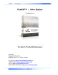
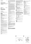
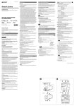
HD_Video Conference Camera
User Manual
¿
TABLE OF CONTENT
Precaution
Application system diagram
Standard Definition operation illustration
Performance
dome parameter
camera parameter
performance & features
Function instruction
positions of control system
Dimension
Functions of remote controller
Instruction
Pan/Tilt operation
camera control
Memory settings
System setting
setting
System setting
Installation instruction
Maintenance service terms
Precaution
1. Precaution
Electrical Safety
Confirm country and local electrical safety standard when using or installing the product
The product itself has no power switch Please stop power supply or plug out power socket when it
can
is not in good working Vide o wire and control wire should be insulated and individual connected
not mix-up with other wires
Transportation with care
Product should be protected against extremes of pressure, vibration and humidity during transportation,
storage and installation. It is transported by integrated packing style
Installation with care
Pleas e read carefully user installation manual when installation Please pick up the camera parts
gently and do not press it, or els e, which may cause malfunction; the camera parts belong to senior optical
products, please do not touch it by your hand in order to avoid scratch for protecting the imaging quality
Requirements to service personnel
All the service work should be done by qualified technicians
Do not disassemble the Pan/Tilt module
Do not disassemble screws and repair the parts of the Pan/Tilt module by yourself. Only qualified and
professional personnel can do this job
Environmental Requirements
Environmental temp:
Air Pressure:
Power consumption:
-40~+60
Humidity:
<95%
86~106 Kpa
Power supply:DC12V
Maximum 12W DC12V
2V
Don't focus the camera on objects with strong light
Don't focus the camera on objects with strong light. Don't focus the camera direct to the sun or
other bright objects no matter when in use or not. Otherwise ,it may affect image quality
Operation illustration
2. Application system diagram
Standard Definition camera operation illustration. for instance as below:
Video cable
To Video input
To VIDEO
YPbPr VIDEO
YPbPr cable
To TV input
Y
Pb
Pr
To HDMI VIDEO
To S VIDEO
To VISCA RS-232C IN
To VISCA IN
RS-232C OUT
To RS-232C
To VISCA IN of
other EVI-D70/D70 Ps
Computer,TV
or VCR with a
video input jack
AC power adaptor
MPA-AC1(supplied)
To AC outlet
To DC IN 12V
Power cord(supplied)
Performance
3. Performance
3.1 Camera parameter
Communications
Electricity
Power supply
Baud rate
Power consumption
Protocol
Built in
Decoder
Address setting
Operation
Environmental
Pan rotation
Working
environmental temperature
Tilt rotation
Environmental humidity
Rotation speed
No-condensation
Pan
Physical
Presets
Remote controller 9
Visca protocol 128
Installation
Stand-up position
net weight
3.2 Camera parameter
Spec
Signal system
Imaging element
Scanning system
Effective pixel (H
Model
KSS 20
Color
PAL/NTSC
1/2.8Type Exmor CMOS Sensor
720P50/60 1080I50/60 1080P25/30 (Optional)
V)
2 Mega pixel
Minimum illumination
Zoom
Focus
Angle Field of view
1.7lux/0.005lux
IRIS Control
Focusing system
Auto/Manual
White balance
Back -light compensation
Auto/Manual
S/N ratio
Electronic shutter speed
Video output port
Wide Dynamic Range
Privacy zone masking
20X Optical,12X Digital
4.7-94 ( mm )
55.4 (W)-2.9 ( T )
Auto/Manual
Off/No
50dB
1/1-1/10000
SDI
Off/No/Auto
24
Performance&Features
3.3 Performance&Features
Remark The parameter for each video camera module is different; please refer to the details in
Chapter 3.2
Ø System
Video signal: PAL color
Pixel: 2 mega
Minimum distance for imaging: (wide view, the nearest settings under Visca protocol):10mm
S/N Ratio: 50 dB
Pan/Tilt: Pan
Tilt:+90
170
, -30
, maximum speed:100
, maximum speed: 90
/S
/S
Ø Input/Output port:
Output: RCA tone socket 1vpp, 75 ohm, Non-balance Sync: Negative
Input/Output control connection port: Visca RS-232C: 8-Core Minisize DIN (input:1; output:1)
Mode of signal control: 9600bps data:8 bit Stop bit:1
Power connection port: JEITA 4
Ø Features
With Fast, wide Pan/Tilt functions
With RS-232C communication and Visca protocol, can control video conference camera by terminal
equipment and computer
Improved quality and definition of digital zoom image by the newest development digital signal
processor (DSP)
Can remove and attenuate IR light by attenuation-filter Besides, this filter can open and close
automatically; it provides image with good quality in high definition and strong brightness in large
scope
Can save 9 presets in memory, it's available for working when necessary
With 1 Multi function IR Remote controller, which is easily and convenient to control video con
ference camera
4
Functions
4. Functions
4.1 positions of control system
Lens
(may fix wide lens)
light of standby
light of power
Sensor of remote
controller.
VIDEO YPbPr
HDMI
Video interface
YPbPr interface
IN RS-232C OUT DCIN12V
DC 12v Power input interface
Output interface
Input interface
HDMI Interface
Functions
4.2 Dimension
110
165
30
154
90
The Size for High definition video conference camera is as below:
POWER
STANDBY
131.56
142
8
6
17 5
Screw thread
1/4-20 UNC,
6.5mm
17 5
8
14
66
Functions
4. 3 Functions of remote controller
POWER
open/close power
DATA SCREEN Enter OSD Menu, Continuous press 6 times (Every time
must be around 1 second), Restart may make the dome restore factory default.
BACK LIGHT press for back light compensation.
AUTO
press for auto-focus.
POWER
FAR
press for far zoom, focus on objects in far distance
NEAR
1
press for near zoom, focus on objects in near distance.
MANUAL
press for Manual Auto/ focus.
POSITION Setting for preset and reset.
BACK LIGHT
DATA SCREEN
2
3
FOCUS
AUTO
NEAR
FAR
MANUAL
6
5
4
PRESET press any number from 0-9 within 2 seconds
after press
RESET
preset
to set preset.
press any number from 0-9 within 2 seconds
after press
reset
to delete preset.
REV
1
2
3
4
5
6
7
8
9
RESET
PRESET
Press any number to see preset.
HOME
STD
7
POSITION
PAN-TILT
press this key to set position in central of front side.
SLOW T focus on near object slowly
HOME
8
10
SLOW W focus on far object slowly
11
FAST T focus on near object fast
12
FAST W focus on far object fast
9
11
13
L/R DIRECTION/SET 1.press 1 in 2 seconds
10
12
after press this key, camera start left to right rotation
ZOOM
SLOW
FAST
13
under upside installation style; Press 2 in 2 seconds after
L/R
DIRECTION SET
press this key, camera start left to right rotation under
upside-down installation style.
Notes:
1. if the remote controller doesn't work, please change batteries.
2. camera can not work if there is any block between remote controller and camera, please make sure the
controller is direct to the sensor when using.
7
Instruction
5. Instruction
5. 1 Pan/Tilt operation
1. Press direction keys to change the direction. If need to change vision angle of camera, please press the
right direction key. Press short time for slow moving, press long time for fast moving.
2. Press "Home" to set position in central of front side.
5. 2 Camera control
Focus
1. Auto focusing: press auto , camera will focus on the central object.
2. Manual focusing: press manual to switch auto and manual focusing. Under model of manual
focusing , press far to set focus in far distance, press near to set focus in near distance.
8
Instruction
Ø Back light imaging
Light behind of the object, which will be black, press
back light
for compensation.
Press again for cancel this function.
DATASCREEN
BACK LIGHT
FOCUS
AUTO
FAR
Far zoom
NEAR
MANUAL
near zoom
Ø Change focus
Press any button of zoom to realize different zoom.
press to near zoom
(far view)
T
W
L/R
DRECTION SET
change zoom slowly
(slow)
TT
W
W
change zoom fast
(fast)
press to far zoom
wide view
9
Instruction
5. 3 Memory settings-preset function
Can set 9 combinations of presets: position, zoom and back light etc.
1. Confirm standby with no glitter.
2. Adjust camera position, zoom and focus on back light.
3. Keeping press preset key, then press any number 1-9 to save presets.
REV
1
2
3
4
5
6
7
8
9
PRESET
Press it
Choose memory settings
Delete memory settings
STD
meanwhile, press
any number to preset
the position
RESET
POSITION
Press any number 1-9 which stands for the saved preset.
Press RESET while press the related number which is saved for
the preset for deletion.
Attention
1 When camera wired into the power supply, it starts automatically from the memory presets.
2 If you want to keep the presets effective when start again after power break off, you can save the presets in
position .
3 Preset is saved or deleted in one position, it can not use other presets when setting. Same preset only can
be saved or deleted in one position.
Menu Setting
6. System setting
MAIN MENU
1
SYSTEM SETTING
CAMERA SETTING
VIDEO OUT
COMM PARA
EXIT
2
Operate remote controller, press DATA SCREEN enter
OSD menu;
Press the arrow keys to select the menu, press left and
right button to set functions;
6.1 System setting
1
SYSTEM SETTING
ZOOM LABEL OFF
HEAD DOWN
OFF
L-R DIRACTION OFF
POS MODE VISCA
INITIAL INFO
DEFAULT
BACK
EXIT
INITIAL INFO
FIRMWAR V2.33 6300
PROTOCOL VISCA
DAURATE 9600
CAM ADDRESS AUTO
BACK
EXIT
Operate remote controller, Press DATA SCREEN
enter OSD menu, press the arrow keys to move to
SYSTEM SETTING press right button to enter
next menu; as the left picture
l ZOOM LABEL
l HEAD DOWN Image inversion OFF Top mount
NO Top-down mount
l L-R DIRACTION Remote controller arrow keys and
the camera running direction
l OFF Remote controller arrow keys consistent with
the direction of camera run
l NO Remote controller arrow keys with the camera
running direction of the opposite
l POS MODE protocol mode, VISCA and FACTORY
for option
l INITIAL INFO Dome initialization information
display; As the left picture shown: Initialization
information including software version number,
PTZ protocols, communication parameters, dome
address, etc.
l DEFAULT Restore to factory default setting
Menu Setting
7. CAMERA SETTING
MAIN MENU
SYSTEM SETTING
CAMERA SETTING
VIDEO OUT
COMM PARA
EXIT
Operate remote controller, Press DATA SCREEN enter
OSD menu, press the arrow keys to move to CAMERA
SETTING press right 1button to enter next menu;
as the left picture
7.1 CAMERA
CAMERA SETTING
EXPOSURE
COLOR
FOCUS
PICTURE
BACK
EXIT
EXPOSURE
AE MODE SET
AGC LIMIT
28DB
SLOW SHUTTER OFF
BLC
OFF
EX-COMP
-1.5DB
BACK
EXIT
AE MODE
AE MODE
SHUTTER
IRIS
BRIGHT
GAIN
BACK
EXIT
AUTO
N/A
N/A
N/A
N/A
EXPOSURE SETTING
1. Press arrow keys to move to EXPOSURE and then press
right button to enter next menu, as the left picture
AE MODE
1.Press right button ,for optional as Follows
AUTO : default setting, auto Iris mode
MANUAL : manual setting
BRIGHT : brightness priority mode
IRIS : iris priority mode
SHUTTER : shutter priority mode
2. Option iris priority mode IRIS , press right-hand
button,save setting.
3. Move the joystick to AE model sub-options IRIS F1.4
press right key, Select the appropriate aperture size,
press right button, save setting.
SHUTTER 1/50 It means shutter speed, when the AE
mode is shutter priority, this function can be set.
IRIS F1.6/0DB It means the size of iris, when the AE mode
is iris priority, this function can be set.
BRIGTH F1.6/0DB It means brightness, when the AE mode
is brightness priority, this function can be set.
AGC LIMIT Automatic Gain range of options 8-28dB
AGC LIMIT The smaller the value, the darker and image
of snowflakes point less; numerical bigger and bright , the image
of snowflakes point more
SLOW SHUTTER Slow shutter control
OFF Close slow shutter
ON Open slow shutter
BLC Backlight compensation function
OFF Close backlight compensation
ON Open backlight compensation
EX-COMP Exposure compensation function
Menu Setting
7.2 CAMERA
MAIN MENU
SYSTEM SETTING
CAMERA SETTING
VIDEO OUT
COMM PARA
EXIT
CAMERA SETTING
EXPOSURE
COLOR
FOCUS
PICTURE
BACK
EXIT
COLOR
WB MODE
R GAIN
B GAIN
BACK
EXIT
ATW
100
100
FOCUS
FOCUS MODE AUTO
BACK
EXIT
COLOR
SETTING
1.Operate remote controller, Press DATA SCREEN enter
OSD menu, press the arrow keys to move to CAMERA
SETTING press right button to enter next menu;
As the left picture:
2.Press arrow keys to move to COLOR and then press
right button to enter next menu, as the left picture
WB MODE White balance mode.
Auto mode of white balance AUTO is the default
mode of intelligent PTZ, environmental detection by
the camera's white balance sensor automatically restore
the true color. When select manual mode MANUAL
you can adjust the values of R GAIN and B GAIN
R GAIN Options range in 1-255, values larger,
represents an increase of more red, hue warm .
B GAIN Options range in 1-255, values larger,
represents an increase of more blue, hue turn cold .
Indoor mode INDOOR hue cool colors
Outdoor mode OUTDOOR hue warmer
ATW Auto tracking mode
OPW Single lock white balance mode
7.3 CAMERA
FOCUS
SETTING
1.Operate remote controller, Press DATA SCREEN
enter OSD menu, press the arrow keys to move to
CAMERA SETTING press right button to enter
next menu; as the left picture
2.Press arrow keys to move to FOCUS and then press
right button to enter next menu, as the left picture
FOCUS MODE Focus ptional.
AUTO Auto Focus
MANUAL Manual Focus
Menu Setting
7.4 CAMERA
MAIN MENU
SYSTEM SETTING
CAMERA SETTING
VIDEO OUT
COMM PARA
EXIT
CAMERA SETTING
EXPOSURE
COLOR
FOCUS
PICTURE
BACK
EXIT
PICTURE
B&W
AUTO
GAMMA
NORMAL
HI-RESOLUTION OFF
NOISE REDUCE OFF
MIRROR
OFF
FLIP
OFF
SHARPNESS
000
BACK
EXIT
4
PICTURE SETTING
1.Operate remote controller, press DATA SCREEN enter
OSD menu, press the arrow keys to move to CAMERA
SETTING press right button to enter next menu;
as the left picture
2.Press arrow keys to move to PICTURE and then press
right button to enter next menu, as the left picture
B&W color / black and white switch mode
AUTO Auto color / black and white switch mode,
intelligent PTZ automatically switched according to
illumination
COLOR set as color mode
BLACK set as black and white mode
GAMMA Gamma correction
HI-RESOLUTION Camera built - in high-resolution
capabilities , refer to the camera types
NOISE REDUCE Noise reduce processing
MIRROR Mirror image function
FLIP The function of Auto flip when the camera
rotates pan 180 degrees
SHARPNESS image acutance settings
Menu Setting
8. Video output and communication parameters setting
MAIN MENU
SYSTEM SETTING
CAMERA SETTING
VIDEO OUT
COMM PARA
EXIT
VIDO OUT
FORMAT
1080P30
RGB/YUV
OFF
HDCP
OFF
OPT CORR
N/A
BACK
EXIT
COMM PAPR
PROTOCOL
BAUDRATE
ADDRESS
BACK
EXIT
VISCA
2400
AUTO
1.Operate remote controller, press DATA SCREEN enter
OSD menu, press the arrow keys to move to VIDEO OUT
press right button to enter next menu; As the left
picture
FORMAT Video output format including 1080P30
1080P25 1080I60 720P60 NTSC 720P50 PAL
CVBS
1080I50 etc for optional.
RGB /YUV Signal output format
HDCP High-bandwidth Digital Content Protection
OFF Closed off high-bandwidth Digital Content Protection
ON Open high-bandwidth Digital Content Protection
OPT CORR Optical correction
2.Operate remote controller, press DATA SCREEN enter OSD
menu, press the arrow keys to move to COMM PAPR press
right button to enter next menu; As the left picture.
PROTOCOL Dome Communation protocol, the optional of VI
PELCO D, PELCO P and so on;
BAUDRATE Setting dome baud rate, optional:
2400bps 4800bps 9600bps 19200bps 38400bps.
ADDRESS Setting dome address, (range of address
001-255), when it is AUTO, the system automatically
assigns the linkage dome address;
5
Installation instruction
Installation instruction
1. To drill 4 M4 screw hole in ceiling
(see above sketch), use 4pc STP4X16
cross screws to fix the upside-down
installation board of D57 on ceiling .
3.Hang the discreteness made in step
2 on the installation board, showed
as the above sketch.
2. Use 4 M3 x5 cross screws to fix
the video conference camera on the
connection board, showed as the
sketch .
4.Use 3pcs M3X5 cross screws to fix
the connection board and installation
board, like above sketch.
Maintenance service terms
10. Maintenance service terms
1. Range of warranty
The product will be maintained free for one year.
The product will be obtained the free maintenance service if the same malfunction appears again within three
payable maintenance months.
Malfunction of products caused by force majeure (such as war, earthquake, lightning strike and so on ), abuse,
non-standard operation, change of construction, non-normal wear or accident are non-free of warranty.
Please prevent from the damage which is caused by heavy pressure , the fierce vibration and soaks in the
process of transportation and storage, which does not belong to the free maintenance range.
Please adopt the way of fission package or original package to transport because the product damage dose
not belong to the free maintenance scope if you use the whole packing way , not the original packing way.
The maintenance services will not be free when the pan/tilt module is disassembled or serviced by the user
voluntarily.
Our company implements the lifetime payable service if the product in malfunction has surpassed the
warranty period.
To the products with defect :if it's in the period of warranty, please fill in the form of warranty information
correctly, describe the trouble in details, and provide original sales. invoice or its copy.
For the damage and loss which was caused by the user's specifically application, factory won't bear any risk
and responsibility. The factory compensation made by breach of faith, negligence or tortious won't exceed the
amount of the products. The factory won't bear any responsibility for the special, unexpected and continue
damage caused by any other reasons.
Our company has the final right of explanation for the above terms.
2. Warranty terms
If the products are within the warranty time, the buyer should fill in the warranty card and send back together
with the products.
3. Shipping
If the product needs repaired , you can return it to the manufacturer through the supplier or directly. If you
choose the later , please contact us in order to speed up the process. And our company only undertake the
one-way freight from manufacturer to customer after maintenance.