1
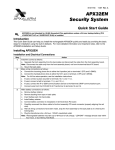
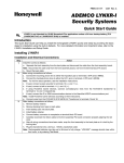
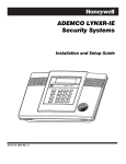
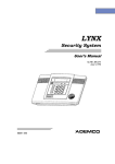
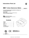
Previous Menu
N8889QS 10/98
/<1;
®
4XLFN6WDUW*XLGH
Introduction
This Quick Start Guide can help you install the LYNX quickly and easily by providing the basic
steps for installation using the built-in defaults. For more detailed information and important
notes, refer to the LYNX Installation Instructions.
The following steps assume that one of the system’s default tables will be used.
For programming data values and Powerline Carrier Devices other than those listed in the default
tables, see the Installation Instructions.
Default Table Summary
Zone Table 1
1
2
3
4
5
6
7
8
9
26
27
28
29
30
31
32
33
92
99
User
Code
Install
Code
------front door
back door
window
motion detector
------------------------loop 3 arm away
loop 2 disarm
loop 4 close device 1
loop 1 restore device 1
loop 3 arm away
loop 2 disarm
loop 4 close device 1
loop 1 restore device 1
duress
silent alarm
1-2-3-4
4-1-1-2
Table 2
Table 3
Table 4
Table 5
------front door
back door
window
motion detector
smoke detector
------------------‡
‡
‡
‡
‡
‡
‡
‡
duress
silent alarm
1-2-3-4
------front door
back door
window
window
window
window
motion detector
smoke detector
‡
‡
‡
‡
‡
‡
‡
‡
duress
silent alarm
1-2-3-4
------front door
back door
window
window
window
window
motion detector
smoke detector
‡
‡
‡
‡
‡
‡
‡
‡
duress
silent alarm
1-2-3-4
------front door
back door
window
motion detector
------------------------‡
‡
‡
‡
‡
‡
‡
‡
duress
silent alarm
1-2-3-4
4-1-1-2
4-1-1-2
4-1-1-2
4-1-1-2
‡ zones 26 – 33 are RF button zones and programmed the same as in Table 1.
Entering Program Mode: installer code + 8 0 0
Interactive Mode
*56 Zone Programming
*83 Sequential Mode
Used to Program
Zone characteristics, report codes, and serial numbers
*84 Assign Zone Voice Descriptors
Exiting Program Mode:
5800 Series transmitter serial numbers
Voice descriptors for each zone
*99 allows re-entry into the Program mode using Installer Code + 8 0 0.
*98 inhibits re-entry into the Programming mode using the Installer Code.
NOTES:
• Tables 2 and 4 support the automatic paging feature (open/close events reported to pager phone
number), and a Powerline Carrier Device programmed as device 8, which closes and stays closed upon
burglary alarms and restores after bell timeout. For other applications or actions (e.g., using a pulsing
siren), see the *80 Powerline Carrier Device Programming section of the Installation Instructions.
• Primary report format for all tables is Ademco’s Contact ID reporting. Tables 2 and 4 also use Contact ID
for secondary reporting. Tables 1, 3, and 5 use 4+1 format for secondary reporting.
• Tables 1 and 5 record all events in the event log. Tables 2, 3, and 4 record only alarms, alarm restores,
troubles, and trouble restores in their event logs.
Steps to Installing LYNX
1.
Separate the front assembly from the back plate and mount the back plate.
DO NOT disconnect the ribbon cable from the terminal strip board. Disconnect the cable only from the front
assembly board.
2.
Make wiring connections as follows:
Connect the incoming phone line to either the 8-position jack or terminals 2 (TIP) and 3 (RING).
Connect the handset phone lines to either the RJ11 jack or terminals 4 (TIP) and 5 (RING).
NOTE: For full line seize operation, see the installation instructions.
If used, connect a piezo sounder to terminals 10 (+) and 11 (–).
If used, connect a bell to terminals 11 (–) and 12 (+).
If using Powerline Carrier Devices, connect com/data/sync/ lines from the PL513 Powerline Interface
Module to terminals 9, 13, and 14 respectively.
Install Powerline Carrier Devices according to their instructions.
Connect wires from the 1332 (1332CN) AC Transformer to terminals 15 and 16.
3.
After all wiring connections are made, carefully reconnect the ribbon cable to the front assembly
PC board connector (properly aligning the red wire), then snap the front assembly to the back plate so
it is held by the locking tabs.
Plug the transformer into a 24-hour, 110VAC unswitched outlet.
Slide out the battery drawer and install either a single 9V alkaline battery or six 1.5V “AA” alkaline
batteries. Use only nonrechargeable, alkaline batteries.
After installing the battery(ies), slide the battery drawer into the back plate only after AC power has
been applied.
4.
Set a programming default:
Enter Programming mode: Installer Code + 8 0 0.
Press *97, then press a number 1-5 to select a default table from the tables listed on page 1.
5.
Program the variable data fields:
Press *24 (RF House ID), then enter the desired 2-digit RF House ID for wireless keypads.
Press *40 (PABX Code, if used), then enter up to 6 digits. If fewer than 6 digits are used, press [*] to
end the field and advance to the next field.
Press *41 (Primary Phone Number), then enter the primary phone number, up to 20 digits. If fewer than
20 digits are used, press [*] to end the field and advance to the next field.
Press *42 (Secondary Phone Number) if used, then enter the secondary phone number, up to 24 digits.
If fewer than 24 digits are used, press [*] to end the field and advance to the next field.
Press *43 (Primary Account Number), then enter the primary account number. If only 3 digits are used,
press [*] to end the field and advance to the next field.
Press *44 (Secondary Account Number) if used, then enter the secondary account number. If only 3
digits are used, press [*] to end the field and advance to the next field.
Press *88 (Pager Characters) if using Default Table 2 or 4, then enter up to 16 digits which may be
required by your pager service (e.g. account number, PIN, etc.). If fewer than 16 digits are used, press
[*] to end the field and advance to the next field.
Press *94 (Download Phone Number), then enter the downloading computer phone number, up to 20
digits. If fewer than 20 digits are used, press [*] to end the field.
6.
Enroll transmitter serial numbers by pressing *83 while in Programming mode, then follow the prompts:
%
'
b Enter the 2-digit zone number of the first transmitter whose serial number you are entering,
then press [*]. The system displays the “C” prompt.
Enter the 7-digit serial number (printed on the transmitter). If you enter an incorrect digit,
press the [#] key to back up to that digit and reenter the correct digit. When all 7 digits are
entered, press the [*] key. Review the displayed serial number. If correct, press [*] again to
save it. The next zone number to be enrolled will display at the “C” prompt for 30 seconds. If
this is the desired zone number, enter its serial number as described above. If not, either
wait 30 seconds or press the [#] key to display the “b” prompt.
The system automatically displays the next zone number for which a serial number may be
enrolled. Press [1] to return to the “C” prompt described above to enroll this zone.
If the zone number displayed is not desired, press [0] to return to the “A” prompt, where you
can then enter a different zone number.
After all serial numbers have been enrolled, return to the “A” prompt, then enter [00] to exit enrollment
mode (blinking “83”). Press [*] + [99] to exit Program mode.
Page 2
7.
Set RF House ID in the wireless keypads as follows:
If using a 5827 wireless keypad, set the keypad’s DIP switches to the RF House ID programmed in
field *24. If using a 5804BD button key or 5827BD keypad, set the RF House ID per its instructions.
If using Powerline Carrier Devices, set their House ID to “A,” (programmed as “0”) or use field *25 to
change the ID to avoid conflicts with existing installations.
8.
Set the Real-Time Clock as follows:
Enter time/date setting mode by entering the Installer Code + [63].
The hour prompt is displayed. Enter the correct hour, then press [*] to accept and advance.
For each subsequent prompt, enter the correct value, then press [*].
You will exit this mode automatically after entering the year, or if no keys are pressed for 1 minute.
9. Test the system as follows:
After installation and programming, enter Installer Code + [5].
To exit Test mode, enter Installer Code + OFF.
10. Assign desired User Codes by following the procedures on the next page and in the User Guide.
Show the user how to perform the various system functions.
11. Perform site-initiated downloader session (to load central station ID) by Installer Code + [#] + [1].
RJ11
8
POSITION
JACK
TO HANDSET
PHONE
LINE
INCOMING
PHONE
LINE
ZONE N/U
PHONE
EARTH GROUND
2
3
4
TIP
RING
TIP
1
5
6
RING (+)
8
7
( )
SOUNDERS PLCD
9
10
11
12
( )
(+)
( )
(+)
AC
15
14
13
16
DATA SYNC
OUT
IN
HARD
WIRED
ZONE
POWERLINE
CARRIER DEVICES
WARNING:
TO PREVENT
RISK OF
SHOCK,
DISCONNECT
TELEPHONE
LINE AT TELCO
JACK BEFORE
SERVICING
THIS UNIT.
ALL OUTPUT CIRCUITS
ARE POWER LIMITED.
PLUG-IN
TRANSFORMER
(e.g., ADEMCO 1332)
CANADA USE 1332CN
LOCAL SOUNDER
DISABLE JUMPER
CUT = DISABLE
}
}
THIS EQUIPMENT SHOULD BE INSTALLED
IN ACCORDANCE WITH THE NATIONAL
FIRE PROTECTION ASSOCIATION’S STANDARD 72, CHAPTER 2 (NATIONAL FIRE
PROTECTION ASSOC., BATTERYMARCH
PARK, QUINCY, MA 02269). PRINTED
INFORMATION DESCRIBING PROPER
INSTALLATION, OPERATION, TESTING,
MAINTENANCE, EVACUATION PLANNING
AND REPAIR SERVICE IS TO BE PROVIDED
WITH THIS EQUIPMENT.
EARTH INCOMING
GROUND PHONE
LINE
PIEZO
HANDSET
PHONE
LINE
BELL
9VAC
15VA
6-14VDC
6-14VDC
30mA max. 120mA max.
(e.g., WAVE2EX)
2k OHMS
EOLR
TO 24HR 110VAC
UNSWITCHED
OUTLET
NOTE: BACKUP BATTERY IS REQUIRED. USE
SINGLE 9V ALKALINE BATTERY (e.g., DURACELL
PC1604 PROCELL) OR SIX 1.5V ALKALINE “AA”
BATTERIES (e.g., DURACELL MN1500).
REPLACE BATTERY AT LEAST EVERY YEAR.
WEEKLY TESTING IS
REQUIRED TO ENSURE
PROPER OPERATION
OF THIS SYSTEM.
BLACK
PL513
YELLOW
POWERLINE INTERFACE
RED
GREEN
THIS DEVICE COMPLIES WITH PART 15 OF FCC RULES.
OPERATION IS SUBJECT TO THE FOLLOWING TWO
CONDITIONS: (1) THIS DEVICE MAY NOT CAUSE HARMFUL
INTERFERENCE, AND (2) THIS DEVICE MUST ACCEPT ANY
INTERFERENCE RECEIVED, INCLUDING INTERFERENCE
THAT MAY CAUSE UNDESIRED OPERATION.
FCC ID: CFS8DLLYNX
CANADA: 17481021165A
COMPLIES WITH FCC RULES, PART 68
FCC REGISTRATION No. 5GBUSA-25623-AL-E
RINGER EQUIVALENCE: 0.6B
1234
4-WIRE MODULAR
PHONE CORD WITH
FLYING LEADS
LYNX WIRING CONNECTIONS
5800 Series Transmitter Loop Numbers: The following illustration shows the compatible
transmitters and their associated input types and loop designations.
LOOP 3
LOOP
2
LOOP
2
(REED)
(REED)
LOOP 2
LOOP
1
LOOP 4
YOU MUST
ENROLL THIS
BUTTON
LOCKING TABS
5801
ENROLL AS "UR" OR "RF"
LOOP 1
(TERMINALS)
LOOP 1
(TERMINALS)
LOOP 1
ALTERNATE
POSITION
FOR LOOP 2
5816
ENROLL AS "RF"
5802/5802CP
ENROLL AS "BR"
5816MN
ENROLL AS "RF"
LOOP
1
YOU MUST
ENROLL THIS
BUTTON
LOOP 4
1
LOOP 3
(PRIMARY)
LOOP 2
(AUX. CENTER)
LOOP 1
(AUX. RIGHT)
2
16
3
LOOP
1
5827
SET HOUSE CODE
LOOP
2
5804
ENROLL AS "BR"
RED WIRE
MARKING
(REED)
LOOP 1
(TERMINALS)
LOOP 2
DISCONNECT
THIS END ONLY!
LOOP
1
5818
ENROLL AS "RF"
5817
ENROLL AS "RF"
5802MN
ENROLL AS "UR" OR "RF"
YOU MUST
ENROLL THIS
BUTTON
LOOP 4
LOOP 3
(TERMINALS)
LOOP 3
5827BD
SET HOUSE CODE
5819
ENROLL AS "RF"
LOOP
1
LOOP 1
5806/5807/5808
••
•
••
NOTE:
MAKE SURE BATTERY
CLIPS ENTER SLOTS
WHEN SNAPPING
FRONT ASSEMBLY
TO BACKPLATE
••
• • ••
• •• • ••
••
BATTERY CLIPS
SET
HOUSE
CODE
(5806 SHOWN)
LOOP
1
LOOP
1
ENROLL AS "RF"
(MOTION)
(MOTION)
5804BD
ENROLL AS "BR"
5849
ENROLL AS "RF"
Page 3
5890
ENROLL AS "RF"
Keypad Functions (when default programming is used)
Security Functions
Checking system status:
(high level messages); press
STATUS
To arm in STAY mode: Press and hold down
To restart exit delay:
(or enter your code +
STAY
(or enter your code +
AWAY
To arm with NO DELAY: Press and hold down
or
AWAY
To disarm the system and silence alarms: User Code +
To bypass a zone(s): User Code +
To turn Chime mode on or off:
BYPASS
+
FUNCTION
+
FUNCTION
) See note below.
FUNCTION
OFF
+
PLAY
+
VOLUME
+
CODE
TEST
To turn Test mode off: User Code +
OFF
+
VOLUME
+ [3] (Up) or [6] (Down)
OFF
+ [3] or [6]
+
LIGHTS ON
#
+
or
LIGHTS OFF
LIGHTS ON
or
+ device number
LIGHTS OFF
+ dev. no.
+ user number + User’s Code (see note below)
To delete a User Code (except Master Code): Master Code +
To turn Test mode on: User Code +
FUNCTION
+ [63]
FUNCTION
FUNCTION
+
VOLUME
To activate or deactivate devices 7 & 8: User Code +
To add a User Code: Master Code +
See note below.
OFF
FUNCTION
Other Functions
To set the time and date: User Code +
To activate or deactivate devices 1-6:
NO DELAY
RECORD
FUNCTION
To restore announcement sounding:
See note below.
CHIME
Volume Control
To adjust message playback/system announcement volume:
To mute system announcements:
+
STAY
AWAY )
+ 2-digit zone number(s)
To stop recording before end of 20 seconds:
To play back a message:
STAY
(applies only if system is armed in Stay mode)
STAY
To arm in AWAY mode: Press and hold down
Message Center
To record a message:
again for secondary messages.
STATUS
To use the defined AUX function: Press and hold
AUX
CODE
+ user number
key 2 secs (4 beeps) + User Code
(To define the AUX function, refer to the procedure in the Aux Function section of the User Manual.
Note: The 1-button paging feature [field *87] is not enabled with the default programming)
NOTE: The Babysitter Code and Installer Code cannot disarm the system unless it was the
code used to arm the system. In addition, if the system is armed by pressing and
holding the Quick-Arm buttons, neither the Babysitter Code nor the Installer Code can
disarm the system.
REFER TO THE INSTALLATION INSTRUCTIONS FOR THE LIMITATIONS OF THIS SYSTEM
AND WARRANTY INFORMATION.
¬146l
N8889QS 10/98
165 Eileen Way, Syosset, New York 11791
Copyright © 1998