1
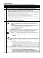
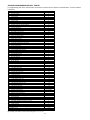
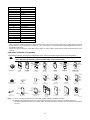
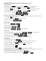
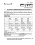
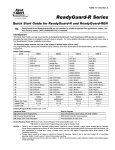
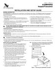
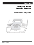
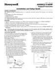
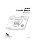
K14117-8
11/07 Rev. A
APX32EN
Security System
Quick Start Guide
UL
APX32EN is not intended for UL985 Household Fire applications unless a 24-hour backup battery (P/N
LYNXRCHKIT-HC or LYNXRCHKIT-SHA) is installed.
Introduction
This Quick Start Guide can help you install the rechargeable APX32EN quickly and easily by providing the basic
steps for installation using the built-in defaults. For more detailed information and important notes, refer to the
APX32EN Installation and Setup Guide.
Installing APX32EN
Installation and Electrical Connections
Step
1.
2.
3.
Action
Install the control as follows:
a. Separate the front assembly from the back plate and disconnect the cable from the front assembly board.
Note: Disconnect the cable only from the front assembly board, not from the terminal block PC board.
b. Mount the back plate.
Make wiring connections as follows:
a. Connect the incoming phone line to either the 8-position jack or terminals 2 (TIP) and 3 (RING).
b. Connect the handset phone lines to either the RJ11 jack or terminals 4 (TIP) and 5 (RING).
Note: For full line seize operation, see the installation instructions.
c. If used, connect a piezo sounder to terminals 10 (+) and 11 (–).
d. If used, connect a bell to terminals 11 (–) and 12 (+).
e. If used, connect the IP or GSM communications device to the Alarmnet LRR/IP communications port.
f. Connect wires from the K10145X10 AC Transformer to terminals 15 and 16.
Make battery connections as follows:
a. Remove battery retainer.
b. Remove backing from tape on back plate.
c. Insert battery pack into back plate.
d. Install battery retainer.
e. Connect battery connector to receptacle on terminal block PC board.
f. Carefully reconnect the ribbon cable to the front assembly PC board connector (properly aligning the red
wire).
g. After all wiring connections have been made, snap the front assembly to the back plate so it is held by the
locking tabs.
h. Plug the transformer into a 24-hour, 110VAC unswitched outlet.
Note: Rechargeable batteries may take up to 48-hours to fully charge. “LOW BAT” message should clear within
four hours, or by entering Test Mode.
LOCKING TABS
RETAINER
NOTE
LYNXRCHKIT-HC
BATTERY PACK SHOWN
BATTERY
PACK
TAPE
LOCKING
TABS
RED WIRE
MARKING
LOCKING
TABS
DISCONNECT
THIS END ONLY!
09012-002-V0
BATTERY
RECEPTACLE
ALL OUTPUT CIRCUITS ARE POWER LIMITED.
FUTURE
USE
PHONE
2
1
3
4
5
STANDARD
HIGH-CAPACITY
BATTERY CONNECTOR
8
7
( )
TIP RING TIP RING
LRR/IP
COMMUNICATIONS
PORT
GSML/GSMVL
COMMUNICATIONS
PORT
6
SOUNDERS
9
10
11
12
( )
(+)
( )
(+)
PLCD
13
14
AC
15
16
DATA SYNC
OUT IN
INCOMING
TELEPHONE
LINE
PREMISES
TELEPHONE
PIEZO
SUPER HIGH-CAPACITY
BATTERY CONNECTOR
BELL
FUTURE
USE
EARTH
GROUND
THE CONTROL IS COMPATIBLE WITH THE
FOLLOWING INTEGRAL RECHARGEABLE
BATTERY PACKS:
P/N LYNXRCHKIT-SC
P/N LYNXRCHKIT-HC
P/N LYNXRCHKIT-SHA
GND
POWERLINE
CARRIER DEVICES
8
POS
JACK
LOCAL SOUNDER
DISABLE SHUNT
REMOVE TO DISABLE
DATA OUT
RJ11
INCOMING
PHONE
LINE
EARTH
GROUND
GND
WARNING:
TO PREVENT
RISK OF SHOCK
DISCONNECT
TELEPHONE LINE
AT TELECOM
JACK BEFORE
SERVICING
THIS UNIT.
UL NOTE
THE MINIMUM WIRE SIZE USED FOR TELEPHONE
INSTALLATIONS MUST BE #26 GAUGE
DATA IN
TO
HANDSET
PHONE
LINE
WIRING
TERMINALS
6-14VDC
30mA max.
6-14VDC
120mA max.
(e.g. WAVE2EX)
WEEKLY TESTING IS
REQUIRED TO ENSURE
PROPER OPERATION
OF THIS SYSTEM
AC
AC
SYNC
COM
DATA
NOTE
USE ONLY THE K10145X10
TRANSFORMER PROVIDED
REPLACE EVERY FOUR YEARS
K10145X10
PLUG-IN
TRANSFORMER
9VAC, 25VA
* WHEN AVAILBLE
X10
ONLY
CONNECTIONS
09012-010-V0
APX32EN WIRING CONNECTIONS
-2-
09012-003
System Programming
For advanced interactive mode programming refer to the end of the System Programming procedure.
Step
1.
2.
3.
4.
Action
Enter Programming mode: Installer Code + 8 0 0
Set a programming default as follows:
Press *97, then press number 1 to select default table. Refer to APX32EN Programming Default Tables.
Program the variable data fields as follows:
a. RF House ID - Press *24, then enter the desired 2-digit RF House ID for wireless keypads.
b. PABX Access Code (if used) - Press *40, then enter up to 6 digits. If fewer than 6 digits are used, press [*] to
end the field and advance to the next field.
c. Primary Phone Number - Press *41, then enter the primary phone number, up to 20 digits. If fewer than 20
digits are used, press [*] to end the field and advance to the next field.
d. Secondary Phone Number (if used ) - Press *42, then enter the secondary phone number, up to 24 digits. If
fewer than 24 digits are used, press [*] to end the field and advance to the next field.
e. Primary Account Number (if used) - Press *43, then enter the primary account number. If only 3 digits are
used, press [*] to end the field and advance to the next field.
f. Secondary Account Number (if used) - Press *44, then enter the secondary account number. If only 3 digits are
used, press [*] to end the field and advance to the next field.
g. Download Phone Number - Press *94, then enter the downloading computer phone number, up to 20 digits. If
fewer than 20 digits are used, press [*] to end the field.
Enhanced Sequential Mode - Press *83, then follow the prompts as follows:
A
01
a.
Zone Number - Enter 2-digit zone number of the first transmitter to have its serial number
entered. The system will announce the Voice Descriptor for the selected zone number, if it is
programmed.
Press [*] to continue. Starting with this zone, the system will search for the first transmitter, which
has all of the following attributes pre-programmed in Zone Programming.
1) The correct input type selected in *56 (RF, UR, or BR programmed)
2) The correct loop number selected in *56
3) No serial number programmed
4) Zone type
Notes: 1. If the first zone number entered does not have one or more of the above attributes, the system will search its
database for the first zone that does, and will display it at the ENROLL SERIAL NUMBER prompt (1b).
2. Pressing 00 exits mode, upon which the prompt “83” blinks, indicating the mode is inactive.
1A zz
1A LC
b.
Enroll Mode - If “L” is displayed, the serial number for this transmitter has already been entered,
however, it may still be confirmed, viewed or deleted.
1) If the transmitter’s serial number has not been previously entered, enter the enroll serial
number mode now by pressing “1”, or copy the last serial number that was entered by
pressing “2”.
2)
If the transmitter’s serial number has been previously entered, it may be viewed by pressing “3”
or deleted by pressing “9”.
Note: If view is selected; each digit will be re-displayed, and the keypad will beep once for digits 1-6, and three times for
the last digit.
3)
Once the serial number has been entered the system will return to the (1A) prompt and “L” will
be displayed.
Note: This point can be faulted and restored and the panel will listen for the transmission.
4)
The serial number/loop number combination that was entered can be confirmed by faulting and
restoring the zone being entered. If the panel receives a transmission that matches the serial
number and loop number entered, the keypad will beep three times, and “C” will be displayed.
This indicates that the serial number transmission has been confirmed to match. No further
transmissions will be received.
Note: When confirming a 4-button key, it assumed that all loops are used and only the serial number is confirmed.
Pressing any key will allow a confirm. Two beeps indicate that the template has been accepted. A single long beep
indicates illegal entries, or duplicate serial number/loop entry.
5)
6)
When the last zone has been entered, the display will remain on that zone. To exit this mode
and return to data field program mode, press 00 at the ZONE NUMBER prompt.
Once all zones have been programmed, test each zone using the system’s Test mode. Do not
use the Transmitter ID Sniffer mode for this, since it will only check for transmission of one zone
on a particular transmitter, and not the zones assigned to each additional loop.
-3-
Step
4.
(Cont.)
Action
1b zz
c.
Serial Number - This prompt can be used to enroll the transmitter serial number via RF
transmission or manually. If using RF Learning proceed to c. 1). If using the manual mode skip to c.
2).
1) RF Learning – Two (2) transmissions (two key depressions at least five second apart) will be
required for BR type or four (4) transmissions (fault, restore and fault, restore) for UR or RF
type. BR type devices can be enrolled only by transmission from BR devices. Likewise, UR and
RF devices can only be enrolled by transmission from a UR or RF device.
If the learned serial number has a different loop number than that entered in *56 the system
will announce the Voice Descriptor, if it is programmed, followed by two beeps and will return
to Prompt (1A) and “L” will be displayed.
If the loop number captured by RF transmission and that entered in *56 mode match, the
system will announce the Voice Descriptor, if it is programmed, followed by three beeps and
return to Prompt (1A) and “LC” will be displayed. No additional transmissions are needed for
confirmation.
Note: BR type devices can be enrolled only by transmission from BR devices. Likewise, UR and RF devices can only be
enrolled by transmission from a UR or RF device.
2)
1b
3)
Note:
6.
7.
8.
9.
If 52 seconds passes and no entry has been made, the system returns to prompt (1A).
Delete Serial Number – This prompt can be used to delete the serial number programmed for the
zone.
1) Enter “0” to discard delete request or “1” to confirm
Exit Programming mode as follows:
*98 inhibits re-entry into the Programming mode using the Installer Code.
*99 allows re-entry into the Program mode using Installer Code + 8 0 0.
Set RF House ID in the wireless keypads as follows:
a. 5827 wireless keypad - Set the keypad’s DIP switches to the RF House ID programmed in field *24.
Set the Real-Time Clock as follows:
a. Enter time/date setting mode by entering the User Code + FUNCTION + [63].
b. The hour prompt is displayed. Enter the correct hour, then press [ADD] to accept and advance.
c. For each subsequent prompt, enter the correct value, then press [ADD].
d. The system will exit this mode automatically after entering the year and pressing [ADD], or if no keys are
pressed for 1 minute.
Test the system as follows:
a. After installation and programming, enter Installer Code + TEST.
b. To exit Test mode, enter Installer Code + OFF.
Assign desired User Codes by following the procedures in the User Guide. Show the user how to perform the
various system functions.
F
5.
Manual Entry – Enter the 7-digit serial number printed on the transmitter. If you enter an
incorrect digit, press the [#] key to backup to prompt (1A) and start over. When all seven digits
are entered press the [*] key.
Once all 7 digits have been entered, press the [*] key. If less than 7 digits are entered, the
keypad will emit a single long beep and return to the (1A) prompt without displaying the
“L”. If more than 7 digits have been entered, the first 6 digits will be saved along with the
last digit that was entered (entering 123456789 yields the serial number 1234569).
d.
Interactive Mode Programming
Interactive Mode
*56 Enhanced Zone Programming
*83 Enhanced Sequential Mode
*84 Assign Zone Voice Descriptors
Used to Program
Zone characteristics, report codes, and serial numbers
5800 Series transmitter serial numbers
Voice descriptors for each zone
Remote Programming (Downloading)
Perform site-initiated downloader session (to load central station ID) by Installer Code + [#] + [1].
-4-
APX32EN PROGRAMMING DEFAULT TABLES
For programming data values and Powerline Carrier Devices other than those listed in the default tables, see the Installation
Instructions.
Function
*20 Installer code
*21 Quick arm enable
*22 Keypad backlight timeout
*23 Forced bypass
*24 RF house ID code
*25 Powerline carrier device house code
*26 Chime-by-zone
*27 Real-time clock display
*29 Daylight saving time start/end month
*30 Daylight saving time start/end weekend
*31 Single alarm sounding per zone
*32 Fire sounder timeout
*33 Alarm bell timeout
*34 Exit delay
*35 Entry delay 1 (zone type 01)
*36 Entry delay 2 (zone type 02)
*38 Confirmation of arming ding
*39 Power up in previous state
*40 PABX access code/Call waiting disable
*41 Primary phone number
*42 Secondary phone number
*43 Primary subscriber account number
*44 Secondary subscriber account number
*46 “Follow Me Reminder” Phone Number
*47 Phone system select
*48 Report format for primary/secondary
*49 Split/dual reporting
*50 15 second dialer delay (burglary)
*51 Periodic test report
*52 First test report offset
*53 Sescoa/radionics select
*54 Lack of usage notification
*55 Reporting channels
*56 Enhanced zone programming
*57 False alarm options
*58 RF jam detection
*59 Exit error report code
*60 Trouble report code
*61 Bypass report code
*62 AC loss report code
*63 Low battery report code
*64 Test report code
*65 Open report code
*66 Arm away/stay report code
*67 RF transmitter low battery report code
*68 Cancel report code
*69 Recent close report code
*70 Alarm restore codes
*71 Trouble restore report code
*72 Bypass restore report code
*73 AC restore report code
*74 Low battery restore report code
*75 RF transmitter low battery restore report code
*76 Test restore report code
*77 Dynamic Signaling Delay/ Dynamic Signaling Priority
*78 Programmable Tone Generation Time
*80 Powerline Carrier Devices
*81 Zone lists for devices
*84 Assign zone voice descriptors
*86 Multi-mode (E-mail notification)
*87 Auxiliary Function/ 1-button paging
*88 Pager characters
*89 Event log 80% full report code
*90 Event logging
*91 Alarm audio verification/remote phone control
*92 Swinger shutdown
*93 Flexible call back
*94 Download phone number
*95 Ring detect count for downloading/remote phone control
Default Master Code
Default Duress Code
Default Value
4112
1
0
0
0,0
0
0
1
3,11
2,1
0
0
1
7,0
3,0
6,0
0
0
------15,15,15,15
----5
7,7
0
0
0
2
0
0
0
See *56 table
7
0
1
1,0
0,0
0,0
1,0
1,0
0
0,0
1,0
1,0
1
1
1,0
0,0
0,0
1,0
1,0
0,0
0,0
0,0
See *80 table
See *81 table
0
0
--0,0
3
2
1
0
--15
1,2,3,4
---
By activating *96, Field 43, and 44 will be changed to 15, 15, 15, 15.
-5-
Zone
Default Value
2
front door
3
back door
4
window
5
motion detector
6
-------
7
-------
8
-------
9
-------
26
loop 3 arm away
27
loop 2 disarm
28
loop 4 arm stay
29
loop 1 no alarm response
30
loop 3 arm away
31
loop 2 disarm
32
loop 4 arm stay
33
loop 1 no alarm response
92
duress
99
silent alarm
NOTES:
• Table 1 supports a Powerline Carrier Device programmed as device 8, which closes and stays closed upon burglary alarms and restores
after bell timeout. For other applications or actions (e.g., using a pulsing siren), see the *80 Device Programming Menu Mode section of
the Installation Instructions.
• Primary report format is Ademco’s Contact ID® reporting. Table 1 records only alarms, alarm restores, troubles, and trouble restores in the
event log.
5800 Series Transmitter Loop Numbers
The following illustration shows the compatible transmitters and their associated input types and loop designations.
The 5800CO, 5800RL, 5802MN, 5802MN2, 5804, 5804BD, 5804BDV, 5804E, 5814, 5816TEMP, 5819, 5819S(WHS &
BRS), 5828/5828V and 5850(GBD) wireless transmitters have not been evaluated by UL.
UL
LOOP 3
LOOP 3
LOOP 4
YOU MUST
ENROLL
THIS
BUTTON
LOOP
1
LOOP 4
YOU MUST
ENROLL
THIS
BUTTON
LOOP 2
LOOP
1
LOOP
1
LOOP 1
ON
OF
F
LOOP 2
LOOP 4
YOU MUST
ENROLL
THIS BUTTON
LOOP 2
LOOP 1
LOOP 3
••
•
••
•
•• •
••• ••••
• ••
5800CO
E N RO L L A S " R F "
5 8 0 0 WAV E
P RO G R A M
HOUSE ID
5800RL
SET
HOUSE ID
5801
ENROLL AS
"UR" OR "RF"
LOOP 1
(PRIMARY)
LOOP 2
(REED)
LOOP 2
(REED)
LOOP 1
(TERMINALS)
LOOP 1
LOOP 1
LOOP 1
5809
ENROLL AS "RF"
5806/5807/5808/5808LST
ENROLL AS "RF"
5814
ENROLL AS "RF"
LOOP 2
(REED)
LOOP 2
(REED)
5 8 0 4 B D / 5 8 0 4 B DV
ENROLL AS "BR"
PROGRAM HOUSE ID
5804/5804E
ENROLL AS "BR"
5802 MN2
ENROLL AS
"UR" OR "RF"
5802 MN
ENROLL AS
"UR" OR "RF"
LOOP 1
(TERMINALS)
LOOP 1
(TEMP
SENSOR)
ALTERNATE
POSITION
FOR LOOP 2
5816
ENROLL AS "RF"
AR
ME
RE
5816MN
ENROLL AS "RF"
5816TEMP
ENROLL AS "RF"
LOOP 1
LOOP 3
(TERMINALS)
5818
ENROLL AS "RF"
LOOP 1
(TERMINALS)
5819
ENROLL AS "RF"
LOOP 3
(AUX.
RIGHT)
5817
ENROLL AS "RF"
LOOP 1
(MOTION)
Y
MESS
AGE
LOOP 1
(INTERNAL
SHOCK
SENSOR
5819S (WHS & BRS)
ENROLL AS "RF"
LOOP 2
(AUX.
CENTER)
D
AD
MIC
LOOP 3
(TERMINALS)
LOOP 1
LOOP 1
(SOUND)
(G
ree
n)
ed
)
(Yell
ow
)
(R
5828/5828V
PROGRAM
HOUSE ID
5849
ENROLL AS "RF"
5850 (GBD)
ENROLL AS "RF"
5890/5890PI
ENROLL AS "RF"
09012-013-V0
Notes: (1) Loop 4 must always be enrolled on the 5801, 5804, 5804BD, 5804BDV, and 5804E transmitters.
(2) 5804E encrypted (High-Security) devices must be activated while the system is in Go/No Go Test Mode. Refer to the
transmitter’s installation instructions for complete details. The system will confirm enrollment of the encrypted device by beeping
two times.
-6-
Keypad Functions (when default programming is used)
Security Functions
Checking system status: STATUS (high level messages); press STATUS
again for secondary messages.
To arm in STAY mode: Press and hold down STAY (or enter your code + STAY ) See note below.
To restart exit delay: STAY (applies only if system is armed in Stay mode and Quick Exit option has been enabled)
To arm in AWAY mode: Press and hold down AWAY (or enter your code + AWAY ) See note below.
To arm with NO DELAY: User Code + AWAY or STAY +
NO DELAY OR
User Code + AWAY INSTANT or STAY INSTANT
To disarm the system and silence alarms: User Code + OFF
See note below.
Note: During Entry Delay or when an Alarm Condition exists the system can be disarmed by entering the User Code.
Entering the OFF key is not required.
To bypass a zone(s): User Code + BYPASS + 2-digit zone number(s)
To turn Chime mode on or off: FUNCTION + CHIME
Message Center
To record a message: FUNCTION +
RECORD
To stop recording before end of 85 seconds: OFF
To play back a message: FUNCTION +
PLAY
To skip a message: [✻]
To delete all messages: FUNCTION +
DELETE
(during message replay)
Volume Control
To adjust message playback/system announcement volume: FUNCTION +
To mute system announcements: FUNCTION +
VOLUME
+
To restore/unmute announcements & volume: FUNCTION +
VOLUME + [3] (Up) or [6] (Down)
OFF
VOLUME + [3] or [6]
Note: If the system was muted during Field Programming it will be unmuted upon exiting.
Other Functions
To set the time and date: User Code + FUNCTION + [63]
To program scheduled events: User Code + FUNCTION + [64], then follow procedure in User Manual.
To add a User Code: Master Code + CODE + user number + User’s Code (see note below)
To delete a User Code (except Master Code): Master Code + CODE + user number
To turn Test mode on: User Code + TEST
To turn Test mode off: User Code +
OFF
To use the defined AUX function: Press and hold AUX key 2 secs (4 beeps) + User Code
(To define the AUX function, refer to the procedure in the Aux Function section of the User Manual. Note: The 1-button
paging feature [field *87] is not enabled with the default programming)
To program Follow Me reminder telephone number: User Code + FUNCTION + [65]
To delete Follow Me reminder telephone number: User Code + FUNCTION + [65]+ ADD
-7-
Remote Phone Control Operation
To remotely disarm system:
+ [1]
To remotely arm in AWAY mode:
+ [2]
To remotely arm in STAY mode:
+ [3]
+ [2] or [3] + [0]
To remotely arm in AWAY or STAY with NO DELAY:
To remotely bypass a zone:
+ [6] + zone no.
To remotely activate forced bypass:
+ [6] + [#]
Note: Force bypass option must be enabled.
To remotely check system status: [*]
+ [9]
To end remote phone session: Hang up or
Speaker Phone Operation
(Note: The ARMED and READY LEDs blink alternately when the Speaker Phone feature is active)
To place a call or answer a call using the speaker phone: [#] + AUX
To Flash (switch between two calls using call waiting): AUX
To hang up and exit speaker phone mode: OFF
To enable/disable (toggle) ringer: [#] + VOLUME
+ AUX
To return the keypad to telephone mode after disarming the system: [#] + AUX
Note: The Babysitter Code and Installer Code cannot disarm the system unless it was the code used to arm the system.
In addition, if the system is armed by pressing and holding the Quick-Arm buttons, neither the Babysitter Code nor
the Installer Code can disarm the system.
REFER TO THE INSTALLATION AND SETUP GUIDE FOR THE LIMITATIONS OF THIS SYSTEM AND
WARRANTY INFORMATION.
5132 North 300 West
Provo, Utah 84604
(800) 216-5232
www.apxalarm.com
ÊK14117-8~Š
K14117-8
11/07 Rev. A