1
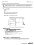
Freescale Semiconductor, Inc.
Document Number: AN5122
Application Note
Rev. 0 04/2015
Using Freescale’s LIN Driver with the
MagniV Family
by: Manuel Rodríguez
1 Introduction
The S12 MagniV family targets the design of
the smallest LIN nodes for both automotive and
industrial applications, providing a highly
integrated and highly reliable solution. In order
to decrease the development time of
applications, Freescale provides a LIN 2.x/SAE
J2602 compliant driver for its devices.
This document is intended to provide an
introduction to Freescale’s LIN driver. The
target audience is expected to have some
experience with the LIN communication
protocol for a deeper treatise of the LIN
communication protocol or the driver. For
further details, refer to the LIN specification
document or the LIN driver manual. This
application note will rely on a “hands-on”
example to get the LIN driver up and running.
Contents
1
Introduction ........................................................................ 1
2
MagniV family overview ................................................... 2
3
Example overview .............................................................. 2
4
Node configuration tool ..................................................... 3
4.1
LDF file and NPF file creation ................................ 4
4.2
LDF file configuration ............................................ 6
4.3
NPF file configuration........................................... 10
5
System initialization ......................................................... 13
6
API overall description..................................................... 15
6.1
Reading and writing a signal ................................. 16
6.2
Send “Go to sleep” command and “wake up”
command ............................................................................. 17
7
References ........................................................................ 17
© Freescale Semiconductor, Inc., 2015. All rights reserved.
_______________________________________________________________________
2 MagniV family overview
MagniV’s increasing portfolio of highly integrated solutions features several microcontrollers aimed to
allow the design of the smallest LIN nodes. Each of these microcontrollers is build in such a way that it
spans the majority of applications that might require a LIN interface, such as window lifters, sunroof
controllers, wipers, body, and control solutions. MagniV LIN portfolio has been created to fulfill the
requirements of the automotive industry and work in space constrained environments such as those
encountered in some automotive applications.
Figure 1 shows MagniV’s LIN portfolio and some of its target applications.
Figure 1. MagniV Portfolio
Figure 1 features MagniV’s LIN portfolio to the date of the document. MagniV portfolio is constantly
changing, so for the updated portfolio visit www.freescale.com/magniv.
3 Example overview
In this application note , a simple LIN application is developed where a S12ZVM Evaluation Board is
being used as master and a S12VR64 Evaluation Board is used as a slave.
Using Freescale’s LIN Driver with the MagniV Family, Rev. 0, 04/2015
2
Freescale Semiconductor
Figure 2. Application flow diagram
Figure 2 features an overview of the application flow diagram. The S12ZVM board reads the state of the
buttons and based on them sends the corresponding signals to the S12VR64 board to activate a relay,
thus simulating the control of a DC motor. In the following sections, we will see how to initialize the
LIN Network using Freescale’s LIN driver and how to setup MagniV hardware to work in conjunction
with Freescale’s LIN driver.
4 Node configuration tool
The node configuration tool allows the user to generate in a straightforward manner the c files that
describe the network architecture, signals, and schedule for the network to follow. The node
configuration tool takes as inputs a LIN Description File (LDF) and a Node Private File (NPF), and
outputs the necessary c files for a node to integrate into the network. The LDF file describes the network
architecture (master and slaves), the signals that each node “publishes” and “subscribes to”, the schedule
tables for the network, speed of the network (baud rate) and version of the protocol to be used. The NPF
file contains the node name, communication channel in use (e.g. SCI, UART, SLIC), clock frequency,
and port used. Every LIN cluster requires one LDF file and one NPF file per node in the network.
The workflow of the node configuration tool is being depicted in Figure 3. It can be seen how the c files
generated by this tool, in combination with the LIN driver, once compiled yield the required files in a
LIN network for each of the supported devices.
Using Freescale’s LIN Driver with the MagniV Family, Rev. 0, 04/2015
Freescale Semiconductor
3
Figure 3. Node configuration tool workflow
4.1 LDF file and NPF file creation
The node configuration code can be generated in three ways:
•
Windows command line
•
Standalone Graphical User Interface (GUI)
•
Eclipse plug-in
The first two methods require the creation of the LDF and NPFs files by hand; in contrast, the last option
includes an intuitive GUI that aids in the creation of the LDF and NPFs files. The Eclipse plug-in option
has been chosen in this document since it significantly decreases the development time. For details of
the remaining methods, refer to the corresponding user guide in the Freescale LIN driver package.
To install the Eclipse plug-in follow the instructions in the Eclipse user manual chapter 3.1 Plug-in
Setup, contained in the documentation folder of the Freescale LIN driver package. A project must be
created in order to work with this tool, please open CodeWarrior Development Studio and click
File>New>Project… as in Figure 4.
Figure 4. Creating a new project in CodeWarrior
Using Freescale’s LIN Driver with the MagniV Family, Rev. 0, 04/2015
4
Freescale Semiconductor
Click on “General” and select “Project” as in Figure 5.
Figure 5. Creating a new project in CodeWarrior
Click “Next>” select the name of the project and click “Finish”.
Right click the project Folder, select “New>Other” as in Figure 6.
Figure 6. Creating LDF and NPFs files
Click on “LIN Node Configuration Files”, select “LDF file” name the file and click “Finish”. See Figure
7 for reference.
Figure 7. Figure 1- Creating LDF and NPFs files
Using Freescale’s LIN Driver with the MagniV Family, Rev. 0, 04/2015
Freescale Semiconductor
5
Follow the procedure for the creation of a LDF file, but select “NPF SCI single-interface”; this file must
be chosen since MagniV devices have the LIN physical layer routed to a SCI channel; name the file and
click “Finish”. Two different instances of this file must be created, one for the master device and one for
slave (a NPF file must be created for each node in the network). If another device is intended to join the
network, the corresponding NPF file must be selected with respect to the device peripherals.
4.2 LDF file configuration
Double click on the LDF file that has been created to open it. Then select the GUI editor as in Figure 8.
A warning will appear and the GUI editor will be shown.
Figure 8. Configuring the LDF file
Select the protocol version and speed for the application as in Figure 9.
Figure 9. Configuring the LDF file
In the “Node definition” section name the master device, set the time base (usually between 5 ms and 10
ms, LIN specification for details) and jitter. Click on the
button to add a slave node, a pop-up
window will appear prompting for the name of the slave. See Figure 10 for reference.
Using Freescale’s LIN Driver with the MagniV Family, Rev. 0, 04/2015
6
Freescale Semiconductor
Figure 10. Configuring the LDF file
Move on to the “Signal definition” section; in this example, three signals are defined:
•
status – Holds the status of the “window”.
•
up_down – Holds the command for the slave node controlling the “window”.
•
error – Error signal used required by the slave.
To add these signals the
button must be pressed, a pop-up window will appear and it must be
configured as in Figure 11 with respect to the required signal properties.
Figure 11. Signal configuration
The defined signals for this example can be seen in Figure 12.
Figure 12. Signals
In this example only unconditional frames are being used, nevertheless the GUI is capable of generating
all the frame types specified by the LIN consortium, i.e. unconditional Frame, event triggered frames,
sporadic frames, and diagnostic frames. As for the signal definition, to define an unconditional frame the
button must be pressed and the following window must be configured. See Figure 13 as a reference.
Using Freescale’s LIN Driver with the MagniV Family, Rev. 0, 04/2015
Freescale Semiconductor
7
Figure 13. Unconditional frame definition
In this example two unconditional frames are defined, one for the status of the “window” and another for
the up and down command. PIDs are being chosen randomly.
Figure 14. Unconditional frames definition
As can be seen in Figure 14 the “S12VR” node has two signals associated with its frame, these signals
must be added with an offset so that they do not overlap, e.g. status offset 0 (size of 2 bits), error offset
of 2 bits to place it after the “status” signal.
Since the other frames will remain unused in this example, these can be left unchanged. The same
procedure as in the unconditional frame could be followed in order to configure the remaining frames if
required.
To configure the “Node attribute definition” section, the
window must be set as in Figure 15.
button must be pressed, and the pop-up
Using Freescale’s LIN Driver with the MagniV Family, Rev. 0, 04/2015
8
Freescale Semiconductor
Figure 15. Node attribute configuration
The configured Node Address (NAD) and initial NAD have been chosen randomly as is up to the
designer to choose its value. The configured NAD specifies the diagnostic address; this is used in the
automatic conflict resolving procedure, as well as in diagnostic and configuration functions, to identify
the node. For this reason, it is a unique number within the cluster.
The product ID is a mandatory part of the node configuration; it consists of the supplier ID 1, the
function ID 2, and the variant ID 3.
The response error identifies the signal name used for LIN error reporting and must be defined in the
signal section.
The time value P2 min defines the minimum time for a slave to prepare its response to a master request
frame and its default value is 50 ms (refer to the LIN specification package for details).
The ST min time defines the minimum time between two slave response frames and its default value is 0
ms.
The N_As_timeout defines the maximum time for transmission of a master request frame on the
transmitter side and its default value is 1000 ms.
1
The supplier ID is assigned by the LIN consortium. For Freescale it is 0x000B (11).
2
The function ID is assigned by the supplier; in this case 0x0020 (18) was chosen.
3
The variant ID must be changed whenever the product is changed, but with an unaltered function.
Using Freescale’s LIN Driver with the MagniV Family, Rev. 0, 04/2015
Freescale Semiconductor
9
The N_Cr_timeout defines the maximum time until reception of the next consecutive frame and its
default value is 1000 ms (refer to the LIN specification package for details chapter 3.2.5 Timing
constraints).
Configurable frames must list all frames (unconditional frames, event triggered frames and sporadic
frames) processed by the slave node.
To move onto the next and last step of the LDF file configuration the “Schedule table definition” must
be selected and the
button must be pressed. The window in Figure 16 will pop-up.
Figure 16. Schedule table configuration
Name the schedule table and select the type of items it will hold. In this example, the only schedule table
that will be used is intended to poll the status of the “window” and send the “up and down command”;
therefore, the item type has been selected as “frame”. The frames related to this schedule table must be
added and a delay between them must be defined. The delay specified for every schedule entry shall be
longer than the jitter and the worst-case frame transfer time.
The file must be verified by pressing
button in your CodeWarrior environment and a window must
pop-up with the following message “This LDF form is correct”.
4.3 NPF file configuration
Double click on the NPF file for the node that will be configured to open it, then select the GUI editor.
A warning will appear and the GUI editor will be shown. Select the “Global definition” section to
configure it.
Figure 17. NPF file configuration
Using Freescale’s LIN Driver with the MagniV Family, Rev. 0, 04/2015
10
Freescale Semiconductor
Select the device that corresponds with the node. In this case, the master node is an S12ZVML128, with
a bus clock frequency of 8 MHz. The idle timeout will send the bus to sleep after this time has elapsed.
The minimum time for this is 4 s and the maximum is 10 s as per the LIN specification. Autobaud
support must not be selected in the master node.
In this case, diagnostic class 1 has been chosen for the application. The diagnostic class must be selected
with respect to the node function; as per the node LIN specification, the following are the description of
each diagnostic class:
•
Diagnostic class 1: Smart and simple devices like intelligent sensors and actuators, requiring
none or very low amount of diagnostic functionality. Actuator control, sensor reading, and fault
memory handling is done by the master node, using signal carrying frames. Therefore, specific
diagnostic support for these tasks is not required. Fault indication is always signal based.
•
Diagnostic class 2: Similar to a class I slave node, but it provides node identification support.
The extended node identification is normally required by vehicle manufacturers. Testers or
master nodes use ISO 14229-1 diagnostic services to request the extended node identification
information. Actuator control, sensor reading and fault memory handling is done by the master
node, using signal carrying frames. Therefore, specific diagnostic support for these tasks is not
required. Fault indication is always signal based.
•
Diagnostic class 3: Slave nodes are devices with enhanced application functions, typically doing
their own local information processing (e.g. function controllers, local sensor/actuator loops).
These slave nodes execute tasks beyond the basic sensor/actuator functionality, and therefore
require extended diagnostic support. Direct actuator control and raw sensor data is often not
exchanged with the master node, and therefore not included in signal carrying frames. ISO
14229-1 [4] diagnostic services for I/O control, sensor value reading and parameter configuration
(beyond node configuration) are required.
Onto the next section “Hardware definition”, the
up must be configured.
button must be pressed and the window that pops-
Figure 18. Node hardware configuration
Name the “new hardware” and select the SCI channel that is routed to the LIN physical layer of your
MagniV device; in this case, SCI channel 0 is routed to the LIN physical layer of both S12ZVM and
S12VR devices. The new configured hardware is shown in Figure 18.
Using Freescale’s LIN Driver with the MagniV Family, Rev. 0, 04/2015
Freescale Semiconductor
11
Figure 19. Network configuration
Name the “new network”, select the corresponding LDF file, name of the node and the previously
defined hardware device and click “Ok”. The new configured network is shown in Figure 19.
The file must be verified by pressing
button in your CodeWarrior environment and a window must
pop-up with the following message “This NPF form is correct”.
To generate the c files for this node click on
. A window will prompt for the output folder select it
and click “OK”. Figure 20 shows the selected folder for this application.
Figure 20. NCF generate files
A new folder must be created and the following text must appear in the console “Generate completed.
Output files already written in folder: /Selected_folder”.
The same procedure must be followed for the slave node, but in this case the Autobaud support can be
selected if desired. The slave configuration used in this example is being showed in Figure 21.
Figure 21. Slave configuration
Using Freescale’s LIN Driver with the MagniV Family, Rev. 0, 04/2015
12
Freescale Semiconductor
To generate the c files for this node click on
. A window will prompt for the output folder select it
and click “OK”. A new folder must be created and the following text must appear in the console
“Generate completed. Output files already written in folder: /Selected_folder”.
5 System initialization
A new project must be created for each device in the network and the LIN driver sources must be
dragged and dropped into each project. For S12Z (CodeWarrior 10.6) microcontrollers, the paths must
be added. Right click on the project->properties->C/C++ Build->Settings->S12Z Compiler-> Access
Paths and click on the
button in the “Search User Paths” section. Click on Workspace… select all the
folders of the LIN driver and click “ok”. See Figure 22 and Figure 23 for reference.
Figure 22. Updating access paths
Using Freescale’s LIN Driver with the MagniV Family, Rev. 0, 04/2015
Freescale Semiconductor
13
Figure 23. Add access paths
For S12 microcontrollers (CodeWarrior Classic IDE) simply drag and drop, the access paths will be
updated automatically. To be able to use the LIN driver in your project include the header definition
“lin.h” in your document.
The hardware must be configured accordingly with the NPFs files, therefore the clock frequency of each
microcontroller has to be adjusted, please refer to the reference manual of your device to perform the
required clock adjustments.
The LIN physical layer of the MagniV device must be enabled, the name of the registers might vary
from device to device, but the procedure remains the same at a high level. The following pseudo-code
illustrates the general procedure to enable the LIN physical layer of a MagniV device, please refer to the
device reference manual.
SELECT_PULL_UP;
// This is done to strengthen the signal
SELECT_SLEW_RATE;
// Optimizes the behavior for the selected baudrate
ENABLE_PHYSICAL_LAYER;
// Enable LIN physical layer
The LIN network must be initialized before trying to initiate communication. This is performed by
calling the following routines declared in the LIN specification package.
•
l_sys_init(void): Performs the initialization of the LIN core (timer initialization). The call to the
l_sys_init is the first call a user must use in the LIN core before using any other API functions.
•
l_ifc_init(l_ifc_handle iii): Initializes the controller specified by the name iii (network name
specified in the NPF file) , i.e., sets up internal functions such as the baud rate. The default
schedule set by the l_ifc_init call will be the L_NULL_SCHEDULE where no frames will be
sent and received. This is the first call a user must perform, before using any other interface
related LIN API functions.
Using Freescale’s LIN Driver with the MagniV Family, Rev. 0, 04/2015
14
Freescale Semiconductor
For a slave node, this is the end of the initialization process for the LIN network. Besides this, it might
be necessary to initialize other modules for other applications but this relies entirely on the application,
therefore it is not covered in this application note. The last point is to enable the interrupts, this can be
done with the command “EnableInterrupts;”.
For a master node a last step is required, the schedule table to be followed must be selected and a routine
must be initialized to follow such schedule, a timer set as “output compare” is commonly used for this
purpose.
The following routines must be called:
•
l_sch_set(l_ifc_handle iii,
l_schedule_handle schedule_iii
l_u8 entry)
iii is the interface name (network name specified in the NPF file), schedule_iii is the name of the
schedule table to be followed, entry is the entry point for the schedule table (the frame to be
transmitted at the next “tick”).
This routine sets up the next schedule to be followed by the l_sch_tick function for a certain
interface. The new schedule will be activated as soon as the current schedule reaches its next
schedule entry point. This routine must be called after “l_ifc_init”
•
l_sch_tick(l_ifc_handle iii) This function follows a schedule. When a frame becomes due, its
transmission is initiated. When the end of the current schedule is reached, this function starts
again at the beginning of the schedule. This function must be called periodically by the master
every “time_base”, this is normally called at the ISR of the configured timer.
Care must be taken no to use the same timer that the driver uses for the schedule. Please see Table 1 for
reference, or refer to the LIN user manual in the LIN driver package for an updated table.
Table 1.
MCU
Channels used
Timer
Channel used
Tim0
0
S12ZVM128
S12ZVL32
S12ZVHY64
S12VR64
Once this has been configured, the master is ready to be used and the interrupts must be enabled.
6 API overall description
The LIN API is a network software layer that hides the details of a LIN network configuration (e.g. how
signals are mapped into certain frames) for a user making an application program for an arbitrary ECU.
Using Freescale’s LIN Driver with the MagniV Family, Rev. 0, 04/2015
Freescale Semiconductor
15
Freescale’s LIN driver integrates this API and is completely compliant with the LIN specification package.
This application note only covers functions related with:
•
Reading and writing a signal.
•
Send “Go to sleep” command and “wake up” command.
For a detailed explanation of the available functions, refer to the LIN specification package or the
FSL_LIN_API_Documentation webpage included in the LIN driver package
(“FSL_LIN_DRIVER”/Documentation/ FSL_LIN_API_Documentation).
6.1 Reading and writing a signal
The available signal types are the following:
•
l_bool
For one bit signals; zero if false, non-zero otherwise
•
l_u8
For signals of the size 2 - 8 bits
•
l_u16
For signals of the size 9-16 bits
To read a scalar signal one of the following functions must be used, depending on the type of the signal
to be read:
•
l_bool
l_bool_rd_sss(void);
•
l_u8
l_u8_rd_sss(void);
•
l_u16
l_u16_rd_sss(void);
Where “sss” is the signal handle which is the name of the network underscore name of the signal,
therefore if the previously defined signal status must be read, this can be achieved by calling the
function “l_u8_rd_LI0_status();”
To read an array the following function must be used:
•
l_bytes_rd_sss (l_u8 start,
/* first byte to read from */
•
l_u8 count,
/* number of bytes to read */
•
l_u8* const data);
/* where data will be written */
This function reads and returns the current values of the selected bytes in the signal. The sum of start
and count shall never be greater than the length of the byte array.
To write a scalar signal one of the following functions must be used, depending on the type of the signal
to be written:
•
l_bool
l_bool_wr_sss(l_bool v);
•
l_u8
l_u8_wr_sss(l_u8 v);
•
l_u16
l_u16_wr_sss(l_u16 v);
Where v is the value to be written to the signal and “sss” is the signal handle as has been already stated.
To write an array the following function must be used:
•
l_bytes_wr_sss (l_u8 start,
/* first byte to write to */
Using Freescale’s LIN Driver with the MagniV Family, Rev. 0, 04/2015
16
Freescale Semiconductor
•
l_u8 count,
/* number of bytes to write */
•
const l_u8* const data);
/* where data is read from */
Sets the current value of the selected bytes in the signal specified by the name sss to the value specified.
The sum of start and count shall never be greater than the length of the byte array, although the device
driver may choose not to enforce this in runtime.
6.2 Send “Go to sleep” command and “wake up” command
To send the “Go to sleep” command the following function must be called:
•
l_ifc_goto_sleep(l_ifc_handle iii);
Where iii is the name of the interface, e.g. “l_ifc_goto_sleep(LI0);”. This function can be called only by
the Master node.
This call requests slave nodes on the cluster connected to the interface to enter bus sleep mode by
issuing one “Go to sleep” command. The “Go to sleep” command will be scheduled latest when the next
schedule entry is due. The l_ifc_goto_sleep will not affect the power mode. It is up to the application to
do this. If the “Go to sleep” command was successfully transmitted on the cluster the go to sleep bit will
be set in the status register
To send the “wake up” command the following function must be called:
•
l_ifc_wake_up(l_ifc_handle iii);
Where iii is the name of the interface, e.g. “l_ifc_wake_up(LI0);”. This function can be called by the
Master node and slave nodes.
The function will transmit one wake up signal. The wake up signal will be transmitted directly when this
function is called. After this function has been called, the schedule table to follow must be set with the
“l_sch_set” function.
7 References
•
LIN Specification Package. Rev 2.2 A, LIN consortium (2010). www.lin-subbus.org.
•
AN2767, “ LIN 2.0 Connectivity on Freescale 8/16-bit MCUs Using Volcano LTP”. Rev 0, Nov
20014. http://notes-application.abcelectronique.com/314/314-66253.pdf.
•
Eclipse_User_Manual in the Freescale LIN driver package, available in freescale.com.
•
LIN_User_Manual in the Freescale LIN driver package, available in freescale.com.
•
FSL_LIN_API_Documentation in the Freescale LIN driver package, available in freescale.com.
Using Freescale’s LIN Driver with the MagniV Family, Rev. 0, 04/2015
Freescale Semiconductor
17
How to Reach Us:
Home Page:
freescale.com
Web Support:
freescale.com/support
Information in this document is provided solely to enable system and software
implementers to use Freescale products. There are no express or implied copyright
licenses granted hereunder to design or fabricate any integrated circuits based on the
information in this document.
Freescale reserves the right to make changes without further notice to any products
herein. Freescale makes no warranty, representation, or guarantee regarding the
suitability of its products for any particular purpose, nor does Freescale assume any
liability arising out of the application or use of any product or circuit, and specifically
disclaims any and all liability, including without limitation consequential or incidental
damages. “Typical” parameters that may be provided in Freescale data sheets and/or
specifications can and do vary in different applications, and actual performance may vary
over time. All operating parameters, including “typicals,” must be validated for each
customer application by customer’s technical experts. Freescale does not convey any
license under its patent rights nor the rights of others. Freescale sells products pursuant
to standard terms and conditions of sale, which can be found at the following address:
freescale.com/SalesTermsandConditions.
Freescale and the Freescale logo are trademarks of Freescale Semiconductor, Inc., Reg.
U.S. Pat. & Tm. Off. All other product or service names are the property of their respective
owners.
© Freescale Semiconductor, Inc. 2015. All rights reserved.
Document Number: AN5122
Rev. 0
04/2015