1
Freescale Semiconductor, Inc.
Application Note
Document Number: AN5135
Rev. 0, 05/2015
3-phase Sensorless PMSM Motor Control
Kit with MagniV MC9S12ZVM
By:
Branislav Zigmund
Contents
1 Introduction
This application note targeted for automotive
applications describes the design of a 3-phase
Permanent Magnet Synchronous Motor (PMSM) vector
control drive with 2-shunt current sensing without a
position sensor.
This cost-effective solution benefits from MC9S12ZVM
device dedicated for motor control. The system is
designed to drive a 3-phase PM synchronous motor.
Following are the supported features:
3-phase PMSM speed Field Oriented Control.
Current sensing with two shunt resistors.
Shaft position and speed estimated by sensorless
algorithm.
Application control user interface using
FreeMASTER debugging tool.
© 2015 Freescale Semiconductor, Inc. All rights reserved.
1 Introduction ............................................................................. 1
2 System concept........................................................................ 2
3 PMSM field oriented control ................................................... 2
3.1 Fundamental principle of PMSM FOC ........................... 2
3.2 PMSM model in quadrature phase synchronous reference
frame ................................................................................ 4
3.3 Controller design ............................................................. 5
3.4 Output voltage actuation ................................................. 7
3.5 Phase current measurement ............................................. 7
3.6 Rotor position/speed estimation ...................................... 9
4 Software implementation on the MC9S12ZVML128 ........... 11
4.1 MC9S12ZVML128 – Key modules for PMSM FOC
control .............................................................................. 11
4.2 MCS12ZVM Device initialization ................................ 14
4.3 Software architecture .................................................... 16
5 FreeMASTER user interface ................................................. 30
6 Conclusion ............................................................................ 31
7 References ............................................................................. 31
PMSM field oriented control
2 System concept
The system is designed to drive a 3-phase PM synchronous motor. The application meets the following
performance specifications:
Targeted at the MC9S12ZVM Evaluation Board (refer to dedicated user manual for
MC9S12ZVM available at www.freescale.com) See section References for more information.
Control technique incorporating:
o
Field Oriented Control of 3-phase PM synchronous motor without position sensor
o
Closed-loop speed control
o
Bi-directional rotation
o
Close-loop current control
o
Flux and torque independent control
o
Position and speed is estimated by Extended BEMF observer.
o
Start up with alignment
o
Reconstruction of three-phase motor currents from two shunt resistors
o
100 μs sampling period with FreeMASTER recorder
FreeMASTER software control interface (motor start/stop, speed setup)
FreeMASTER software monitor
FreeMASTER software graphical control page (required speed, actual motor speed, start/stop
status, DC-Bus voltage level, motor current, system status)
FreeMASTER software speed scope (observes actual and desired speeds, DC-Bus voltage and
motor current)
FreeMASTER software high-speed recorder (reconstructed motor currents, vector control
algorithm quantities)
DC-Bus over-voltage and under-voltage, over-current, overload and start-up fail protection.
3 PMSM field oriented control
3.1 Fundamental principle of PMSM FOC
High-performance motor control is characterized by smooth rotation over the entire speed range of the
motor, full torque control at zero speed, and fast acceleration/deceleration. To achieve such control,
Field Oriented Control is used for PM synchronous motors.
The FOC concept is based on an efficient torque control requirement, which is essential for achieving a
high control dynamic. Analogous to standard DC machines, AC machines develop maximal torque
when the armature current vector is perpendicular to the flux linkage vector. Thus, if only the
fundamental harmonic of stator-mmf is considered, the torque Te developed by an AC machine, in
vector notation, is given by the following equation:
3-phase Sensorless PMSM Motor Control Kit with MagniV MC9S12ZVM Application Note Rev. 0 05/2015
2
Freescale Semiconductor, Inc.
PMSM field oriented control
Equation 1
where pp is the number of motor pole-pairs, is is stator current vector and ψs represents vector of the
stator flux. Constant 3/2 indicates a non-power invariant form of transformation used.
In instances of DC machines, the requirement to have the rotor flux vector perpendicular to the stator
current vector is satisfied by the mechanical commutator. Because there is no such mechanical
commutator in AC Permanent Magnet Synchronous Machines (PMSM), the functionality of the
commutator has to be substituted electrically by enhanced current control. This suggests the orientating
of the stator current vector in so that the component of stator current magnetizing the machine (flux
component) is isolated from the torque producing component.
This can be accomplished by decomposing the current vector into two components projected in the
reference frame, often called the dq frame that rotates synchronously with the rotor. It has becomes a
standard to position the dq reference frame such that the d-axis is aligned with the position of the rotor
flux vector, so that the current in the d-axis will alter the amplitude of the rotor flux linkage vector. The
reference frame position must be updated so that the d-axis should be always aligned with the rotor flux
axis.
Because the rotor flux axis is locked to the rotor position, when using PMSM machines, a mechanical
position transducer or position observer can be utilized to measure the rotor position and the position of
the rotor flux axis. When the reference frame phase is set such that the d-axis is aligned with the rotor
flux axis, the current in the q-axis represents solely the torque producing current component.
What further results from setting the reference frame speed to be synchronous with the rotor flux axis
speed is that both d and q axis current components are DC values. This implies utilization of simple
current controllers to control the demanded torque and magnetizing flux of the machine, thus
simplifying the control structure design.
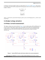
Figure 1 shows the basic structure of the vector control algorithm for the PM synchronous motor. To
perform vector control, it is necessary to perform the following four steps:
Measure the motor quantities (DC link voltage and currents, rotor position/speed).
Transform measured currents into the two-phase system (α, β) using a Clarke transformation.
After that transform the currents in α, β coordinates into the d, q reference frame using a Park
transformation.
The stator current torque (isq) and flux (isd) producing components are separately controlled in d,
q rotating frame.
The output of the control is stator voltage space vector and it is transformed by an inverse Park
transformation back from the d, q reference frame into the two-phase system fixed with the
stator. The output three-phase voltage is generated using a space vector modulation.
To be able to decompose currents into torque and flux producing components (isd, isq), position of the
motor-magnetizing flux has to be known. This requires knowledge of accurate rotor position and
velocity. This application note deals with the sensorless FOC control where the position and velocity is
obtain by help of position/velocity estimator.
3-phase Sensorless PMSM Motor Control Kit with MagniV MC9S12ZVM Application Note Rev. 0 05/2015
Freescale Semiconductor, Inc.
3
PMSM field oriented control
Figure 1. Field oriented control transformations
3.2 PMSM model
reference frame
in
quadrature
phase
synchronous
Quadrature phase model in synchronous reference frame is very popular for field oriented control
structures, because both controllable quantities, current and voltage, are DC values. This allows to
employ only simple controllers to force the machine currents into the defined states. Furthermore full
decoupling of the machine flux and torque can be achieved, which allows dynamic torque, speed and
position control.
The equations describing voltages in the three phase windings of a permanent magnet synchronous
machine can be written in matrix form as follows:
Equation 2
where the total linkage flux in each phase is given as:
Equation 3
where Laa, Lbb, Lcc, are stator phase self-inductances and Lab=Lba, Lbc=Lcb, Lca=Lac are mutual inductance
between respective stator phases. The term ΨPM represents the magnetic flux generated by the rotor
permanent magnets, and θe is electrical rotor angle.
3-phase Sensorless PMSM Motor Control Kit with MagniV MC9S12ZVM Application Note Rev. 0 05/2015
4
Freescale Semiconductor, Inc.
PMSM field oriented control
Figure 2. Orientation of stator (stationary) and rotor (rotational) reference frames, with
current components transformed into both frames
The voltage equation of the quadrature phase synchronous reference frame model can be obtained by
transforming the three phase voltage equations (Equation , Equation ) into a two phase rotational frame
which is aligned and rotates synchronously with the rotor as shown in Figure 2Error! Reference source
not found.. Such transformation, after some mathematical corrections, yields the following set of
equations:
Equation 4
It can be seen that Equation represents a non-linear cross dependent system, with cross-coupling terms
in both d and q axis and back-EMF voltage component in the q-axis. When FOC concept is employed,
both cross-coupling terms shall be compensated in order to allow independent control of current d and q
components.
3.3 Controller design
Most common practice is to control the stator current torque (isq) and flux (isd) producing components
separately by two PI controllers. Typical FOC control structure is shownin Figure 3.
3-phase Sensorless PMSM Motor Control Kit with MagniV MC9S12ZVM Application Note Rev. 0 05/2015
Freescale Semiconductor, Inc.
5
PMSM field oriented control
Figure 3. FOC Control Structure
Following basic steps should be kept in mind to accomplish the FOC control:
Obtain motor currents, DC link voltage rotor position/speed.
Transform measured currents by help of the rotor position into the d, q reference frame.
The stator current torque (isq) and flux (isd) producing components are separately controlled in d,
q rotating frame by two PI controllers.
Transform calculated voltage vector from the d, q reference frame back to three-phase voltages.
Design of the controllers is governed by following pair of equations, derived from Equation after crosscoupling terms compensation:
Equation 5
Equation 6
which describes the model of the plant for d and q current loop. It is obvious that both Equation 5 and
Equation are structurally identical, therefore the same approach of controller design can be adopted for
both d and q controllers. The only difference is in values of d and q axis inductances, which results in
different gains of the controllers.
3-phase Sensorless PMSM Motor Control Kit with MagniV MC9S12ZVM Application Note Rev. 0 05/2015
6
Freescale Semiconductor, Inc.
PMSM field oriented control
Considering closed loop feedback control of a plant model as in Equation and Equation , using stanard
PI controllers, then the controller proportional and integral gains can be derived, using a pole-placement
method, as follows:
Equation 7
Equation 8
where ω0 represents the system natural frequency [rad/sec] and ξ is the Damping factor [-] of the current
control loop.
3.4 Output voltage actuation
3.5 Phase current measurement
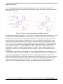
The 3-phase voltage source inverter shown in Figure 4 uses two shunt resistors (R68 and R48) placed in
each of the inverter leg as phase current sensors. Stator phase current which flows through the shunt
resistor produces a voltage drop which is interfaced to the AD converter of microcontroller through
conditional circuitry (refer to MC9S12ZVML128 Evaluation Board User Manual available at
freescale.com).
Figure 4. 3-phase DC/AC inverter with shunt resistors for current measurement
3-phase Sensorless PMSM Motor Control Kit with MagniV MC9S12ZVM Application Note Rev. 0 05/2015
Freescale Semiconductor, Inc.
7
PMSM field oriented control
Figure 5 shows gain setup and input signal filtering circuit for two internal operational amplifier
integrated on MC9S12ZVM which provides the conditional circuitry and adjusts voltages to fit into the
ADC input voltage range.
Figure 5. Phase current measurement conditional circuitry
The phase current sampling technique is a critical issue for detection of phase current differences and for
acquiring full three phase information of stator current by its reconstruction. Phase current flowing
through shunt resistors produces a voltage drop which needs to be appropriately sampled by the AD
converter when low-side transistors are switched on. The current cannot be measured by the current
shunt resistors at an arbitrary moment. This is because that the current only flows through the shunt
resistor when the bottom transistor of the respective inverter leg is switched on. Therefore considering
Figure 4, phase A current is measured using the R68 shunt resistor and can only be sampled when the
transistor Q6 is switched on. Correspondingly, the current in phase B can only be measured if the
transistor Q2 is switched on, and the current in phase C can only be measured if the transistor Q4 is
switched on. In order to get an actual instant of current sensing, voltage waveform analysis has to be
performed.
Generated duty cycles (phase A, phase B, phase C) of two different PWM periods are shown in Figure
6. These phase voltage waveforms correspond to a center-aligned PWM with sine-wave modulation. As
shown in the following figure, (PWM period I), the best sampling instant of phase current is in the
middle of the PWM period, where all bottom transistors are switched on. However, not all three currents
can be measured at an arbitrary voltage shape. PWM period II in the following figure shows the case
when the bottom transistor of phase A is ON for a very short time. If the ON time is shorter than a
certain critical time (depends on hardware design), the current cannot be correctly measured.
3-phase Sensorless PMSM Motor Control Kit with MagniV MC9S12ZVM Application Note Rev. 0 05/2015
8
Freescale Semiconductor, Inc.
PMSM field oriented control
Figure 6. Generated phase duty cycles in different PWM periods
In case of standard motor operation where the supplied voltage is generated using the space vector
modulation, the sampling instant of phase current takes place in the middle of the PWM period in which
all bottom transistors are switched ON. If the modulation index of applied SVM technique increases
there is an instant when one of the bottom transistors is switched ON for a very short time period.
Therefore, only two currents are measured and the third one is calculated from the following equation:
Equation 9
Therefore, a minimum ON time of the low-side switch is required for three phase current reconstruction.
3.6 Rotor position/speed estimation
The first stage of the proposed overall control structure is alignment algorithm of rotor PM to set an
accurate initial position. The alignment algorithm applies DC voltage to phase A for a certain period.
This will cause the rotor to move to "align" position, where stator and rotor fluxes are aligned. The rotor
position in which the rotor stabilizes after applying DC voltage is set as zero position. The alignment
algorithm allows applying a full startup torque to the motor.
In the second stage, the field-oriented control is in open-loop mode, in order to move the motor up to a
speed value where the observer provides sufficiently accurate speed and position estimations. As soon as
the observer provides appropriate estimates, the rotor speed and position calculation is based on the
estimation of a BEMF in the stationary reference frame using a Luenberger type of observer.
When the PMSM reaches a minimum operating speed, a minimum measurable level of BEMF is
generated by the rotor’s permanent magnets. The BEMF observer then transitions into the closed-loop
mode. The feedback loops are then controlled by the estimated angle and estimated speed signals from
the BEMF observer.
This estimation method for the position and angular speed is based on the motor mathematical model
with an extended electromotive force function. This extended BEMF model includes both position
information from the conventionally defined BEMF and the stator inductance. This enables extraction of
the rotor position and velocity information by estimating the extended BEMF only.
3-phase Sensorless PMSM Motor Control Kit with MagniV MC9S12ZVM Application Note Rev. 0 05/2015
Freescale Semiconductor, Inc.
9
PMSM field oriented control
The observer is applied to PMSM motor with an estimator model excluding the extended BEMF term.
Then the extended BEMF term can be estimated using the observer as shown in Figure 7, which uses a
simple observer of PMSM stator current. The BEMF observer presented here is realized within the
rotating reference frame (dq). The estimator of dq-axis consists of the stator current observer based on
RL motor circuit with estimated motor parameters. This current observer is fed by the sum of the actual
applied motor voltage, cross-coupled rotational term, which corresponds to the motor saliency (Ld-Lq),
and compensator corrective output. The observer provides BEMF signals as disturbance because BEMF
is not included in the observer model.
Figure 7. Luenberger type stator current observer acting as state filter for BEMF
To obtain the speed and position information from the position error, another algorithm ‘A tracking
observer’ is used. This algorithm adopts the phase-locked loop mechanism. It requires a single input
argument as phase error. Such phase tracking observer, with standard PI controller used as the loop
compensator is shown in Figure 8.
Figure 8. Block diagram of proposed PLL scheme for position estimation
3-phase Sensorless PMSM Motor Control Kit with MagniV MC9S12ZVM Application Note Rev. 0 05/2015
10
Freescale Semiconductor, Inc.
Software implementation on the MC9S12ZVML128
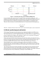
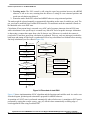
4 Software implementation on the MC9S12ZVML128
4.1 MC9S12ZVML128 – Key modules for PMSM FOC
control
The MC9S12ZVML128 device includes modules such as the Pulse Width Modulator with Fault
Protection (PMF), a Programmable Trigger Unit (PTU), an Analogue-to-Digital Converter (ADC), and a
Timer module (TIM) and a Gate Drive Unit (GDU) suitable for control applications, in particular, motor
control applications. These modules are directly interconnected and can be configured to meet various
motor control application requirements. Figure 9 shows module interconnection for a typical PMSM
Sensorless application. The modules are described below and a detailed description can be found in the
MC9S12ZVMRMV1, MC9S12ZVM-Family Reference Manual available at freescale.com
4.1.1 Module interconnection
The modules involved in output actuation, data acquisition and the synchronization of actuation and
acquisition, form the so-called Control Loop. This control loop consists of the PMF, GDU, ADC and
PTU modules. The control loop is very flexible in operation and can support static, dynamic or
asynchronous timing.
The PTU and ADC are based on list architecture; which means they operate using lists stored in
memory. These lists define the trigger points for the PTU, commands for the ADC, and results from the
ADC.
Each control loop cycle is started by a PMF reload event. The PMF reload event restarts the PTU time
base. If the PTU is enabled, the reload is immediately passed on as a ptu_reload event to the ADC and
GDU modules.
The PMF generates the reload event at the required PWM reload frequency. The PMF reload event
causes the PTU time base to restart, to acquire the first trigger time from the list, and to generate the
ptu_reload signal for the ADCx to start loading the ADC conversion command from the Command
Sequence List (CSL).
When the trigger time is encountered, the corresponding PTU trigger generates the trigger_x signal for
the associated ADC. For simultaneous sampling, the PTU generates two simultaneous trigger_x signals,
one for each ADC. At the trigger_x signal assertion the ADC starts the first conversion of the next
conversion sequence in the CSL (the first A/D command is already downloaded) (MC9S12ZVMRMV1,
MC9S12ZVM-Family Reference Manual, available at freescale.com ).
From the above mentioned, this implies that the PTU module serves as a delay block which can schedule
several acquisitions of state variables relative to the start of the PWM period and within one PWM
period.
3-phase Sensorless PMSM Motor Control Kit with MagniV MC9S12ZVM Application Note Rev. 0 05/2015
Freescale Semiconductor, Inc.
11
Software implementation on the MC9S12ZVML128
Figure 9. Module interconections
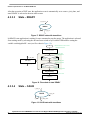
4.1.2 Module involvement in digital PMSM Sensorless
control loop
This section will discuss timing and modules synchronization to accomplish PMSM Sensorless FOC on
the MC9S12ZVM128L and the internal hardware features.
The time diagram of the automatic synchronization between PWM and ADC in the PMSM application
is shown in Figure 10.
3-phase Sensorless PMSM Motor Control Kit with MagniV MC9S12ZVM Application Note Rev. 0 05/2015
12
Freescale Semiconductor, Inc.
Software implementation on the MC9S12ZVML128
PMFMOD
VAL0
PWM counter
100 us
0
PMF phA out
A_top
A_bot
PMF half cycle reload
every fourth opportunity
PWM Reload
Trig. 0
Trig. 1
deadtime
PMF half cycle reload
every fourth opportunity
Trig. 0
Trig. 1
Trig. 0
Trig. 1
PTU counter
PTU triggers
Delay in
order for
DMA to load
ADC list
Active ADC
sample point
phase
AB
Udcb EOC
temp interrupt
phase
AB
Udcb EOC
temp interrupt
phase
AB
Udcb EOC
temp interrupt
ADC conversion
commands execution
FOC
Calculations
ISR service routine
Free for application use
FOC
Free for application use
Calculations
Figure 10. Time Diagram of PWM and ADC Synchronization
The PMSM Sensorless FOC control with two shunt measurement is based on static timing; meaning the
trigger point instances of the ADC conversions are located at same place within one control loop cycle.
Each control cycle starts with PWM reload signal. The reload signal is generated every second PWM
period. The PWM reload signal itself also triggers the reload of the Trigger List in the PTU module, as
well as restarting the PTU counter. When the PTU counter reaches the predefined value in the trigger list
(Trig.0 and Trig.1), the PTU triggers ADC measurement. At the time of Trig.0, two simultaneous
measurements of phase currents in phase A and phase B are triggered. Two other simultaneous
measurements are triggered at time of Trig.1, one for Temperature and one for the DC-Bus voltage. The
ADC conversion results are automatically stored into a predefined queue in memory.
The CPU is triggered by the ADC conversion complete interrupt service routine. Based on the stored
ADC values the current PI controllers calculate new PWM duty cycles. These duty cycles will be
updated to GDU at next reload event.
The TIM, PTU, GDU and ADC peripherals are based on the bus clock. To achieve a higher resolution of
PWM, the PMF module is supplied by a core clock. The core clock is double that of the bus clock.
3-phase Sensorless PMSM Motor Control Kit with MagniV MC9S12ZVM Application Note Rev. 0 05/2015
Freescale Semiconductor, Inc.
13
Software implementation on the MC9S12ZVML128
4.2 MCS12ZVM Device initialization
4.2.1 CPMU
For proper operation the CPMU needs to have stable power supply. The power supply is stable when the
GDUF_GLVLSF is cleared. The application is using Internal Reference which provides a 1MHz internal
clock (CPMUOSC_OSCE = 1). Out of the 1MHz Internal clock the bus and core clock is derived by
following settings:
CPMUREFDIV_REFFRQ = 0;
CPMUSYNR_SYNDIV = 49;
CPMUSYNR_VCOFRQ = 3;
CPMUPOSTDIV_POSTDIV = 0;
Set the bus and core clock to 50MHz and 100MHz respectively. The SW needs to wait until the PLL
lock (CPMUIFLG_LOCK set to 1).
The CPMU module settings provide also possibility to enable the High Temperature Sensor which is
routed than to ADC channel.
4.2.2 PMF
The Pulse Width Modulator with Fault Protection (PMF) module is configured to generate a centrealigned (PMFCFG0_EDGEx = 0) PWM with a frequency of 20 kHz (PMFMODA = 2500). In order to
protect the MOSFET devices in the same leg of the inverter, deadtime is set to approximately 0.25 us
(PMFDTMA = 25). PWM generator A runs as the master and generates the Reload Signal as a
synchronization signal for the other submodules (PMFCFG2_REV[0:1] = 1). The reload signal is
generated at every fourth PWM opportunity (PMFFQCA = 3). Pair A, Pair B and Pair C PWMs are
synchronized to PWM generator A (PMFCFG0_MTG = 0).
A PWM pulse width PMFVAL registers are double buffered and are swapped when GLDOK is set and
the PWM reload signal occurs. The GLDOK is an external signal generated by the PTU module. The
GLDOK is enabled at the PWM module (PMFENCA_GLDOKA = 1)
4.2.3 PTU
The Programmable Trigger Unit (PTU) is intended to completely avoid CPU involvement in the time
acquisitions of state variables during the control cycle.
The PTU module consists of 2 trigger generators (TG). For each TG, a separate enable bit is available,
so that both TGs can be enabled independently. Trigger generator 0 is connected to ADC0, and trigger
generator 1 is connected to ADC1. The trigger generation of the PTU module is synchronized to the
incoming reload event. This reload event resets and restarts the internal time base counter and makes
sure that the first trigger value from the actual trigger list is loaded. Furthermore, the corresponding
ADC is informed that a new control cycle has started.
If the counter value matches the current trigger value, then a trigger event is generated. In this way, the
reload event is delayed by the number of bus clock cycles defined by the current trigger value. All
acquisition time values are stored inside the global memory map, basically, inside the system memory as
a three dimensional array of integers (PTUTriggerEventList[][][]). The exact location of the acquisition
3-phase Sensorless PMSM Motor Control Kit with MagniV MC9S12ZVM Application Note Rev. 0 05/2015
14
Freescale Semiconductor, Inc.
Software implementation on the MC9S12ZVML128
time values (PTUTriggerEventList[][][]) in the system memory is given by the linker command file and
linked to the PTU module during the initialization phase.
PTUPTRL = (uint8_t)((long)PTUTriggerEventList);
PTUPTRM = (uint8_t)(((long)PTUTriggerEventList) >> 8);
PTUPTRH = (uint8_t)(((long)PTUTriggerEventList) >> 16);
Each trigger generator uses only one list to load the trigger values from the memory. The pointers for the
primary (TG0L0IDX/ TG1L0IDX) and alternate (TG0L1IDX/ TG1L1IDX) lists are equal.
TG0L1IDX = (uint8_t)(((long)&PTUTriggerEventList[0][0][0] - (long)PTUTriggerEventList) >> 1);
TG1L0IDX = (uint8_t)(((long)&PTUTriggerEventList[1][0][0] - (long)PTUTriggerEventList) >> 1);
TG1L1IDX = (uint8_t)(((long)&PTUTriggerEventList[1][0][0] - (long)PTUTriggerEventList) >> 1);
The trigger generator is using only one physical list of trigger events, even if the trigger generator logic
is switching between both pointers. The PTU module generates the LDOK signal used to inform other
modules that the double buffered registers were updated by software.
4.2.4 GDU
The Gate Drive Unit (GDU) is a Field Effect Transistor (FET) pre-driver designed for three-phase motor
control applications. The following GDU features are used in PMSM FOC sensorless control
Charge Pump: The charge pump is used to maintain the high-side driver gate source voltage
VGS when PWM is running at a 100% duty cycle. The clock for the charge pump is set to be
(GDUCLK2_GCPCD = 2)
Desaturation Error: The GDU integrates three desaturation comparators for the low-side FET
pre-drivers and three desaturation comparators for the high-side FET pre-drivers. The
desaturation level is set to be 1.35V (GDUDSLVL = 0x77) for both low-side and high-side FET.
A blanking time during the FET transients needs to be employed. The blanking time is set to be
approximately 8 us (GDUCTR = 0x13).
Current Sense Amplifiers: Internal current sense amplifier 0 and 1 (GDUE_GCSE0 = 1 and
GDUE_GCSE1 = 1) is used to measure motor phase currents in phase A and phase B. The
output of the current sense amplifier 0 is routed internally to ADC0 channel 0. The output of the
current sense amplifier 1 is routed internally to ADC1 channel 1.
4.2.5 ADC
The MC9S12ZVML128 uses two independent Analogue-to-Digital Converters (ADC). Both ADCs are
n-channel multiplexed input successive approximation analogue-to-digital converters. The List Based
Architecture (LBA) provides a flexible conversion sequence definition, as well as flexible oversampling.
Both ADC conversion command lists are stored inside the global memory map, basically, inside the
system memory as two dimensional arrays of bytes (ADC0CommandList[][], ADC1CommandList[][]).
The exact location of the ADC conversion commands in the system memory is given by the linker
command file and linked to the respective ADC module during the initialization phase. The same
strategy is used for the ADC Results. The Conversion results are stored in an array of shorts
(ADC0ResultList[], ADC1ResultList[]) located in system memory.
3-phase Sensorless PMSM Motor Control Kit with MagniV MC9S12ZVM Application Note Rev. 0 05/2015
Freescale Semiconductor, Inc.
15
Software implementation on the MC9S12ZVML128
// ADC0 Command Base Pointer
ADC0CBP_0 = (uint8_t)(((long)ADC0CommandList) >> 16);
ADC0CBP_1 = (uint8_t)(((long)ADC0CommandList) >> 8);
ADC0CBP_2 = (uint8_t)((long)ADC0CommandList);
// ADC0 Result Base Pointer
ADC0RBP_0 = (uint8_t)(((long)ADC0ResultList) >> 16);
ADC0RBP_1 = (uint8_t)(((long)ADC0ResultList) >> 8);
ADC0RBP_2 = (uint8_t)((long)ADC0ResultList);
// ADC1 Command Base Pointer
ADC1CBP_0 = (uint8_t)(((long)ADC1CommandList) >> 16);
ADC1CBP_1 = (uint8_t)(((long)ADC1CommandList) >> 8));
ADC1CBP_2 = (uint8_t)(long)ADC1CommandList);
// ADC1 Result Base Pointer
ADC1RBP_0 = (uint8_t)(((long)ADC1ResultList) >> 16);
ADC1RBP_1 = (uint8_t)(((long)ADC1ResultList) >> 8);
ADC1RBP_2 = (uint8_t)((long)ADC1ResultList);
The ADC conversion clocks are set to be 8.33 MHz (ADC0TIM = 2; ADC1TIM = 2). The results are
stored in memory as 12-bit (ADC0FMT_SRES = 4; ADC1FMT_SRES = 4) left-justified data
(ADC0FMT_DJM = 0; ADC1FMT_DJM = 0).
Conversion flow of both ADCs is controlled by internal signals (generated by the PTU) and by the
DataBus (ADC0CTL_0_ACC_CFG = 3; ADC1CTL_0_ACC_CFG = 3). The results are stored in
system memory even if commutation occurs when conversion is ongoing ( ADC0CTL_0_STR_SEQA =
1; ADC1CTL_0_STR_SEQA = 1).
The ADC1 schedules the end of list interrupt (ADC1CONIE_1_EOL_IE = 1) to perform application
logic and calculate the PMSM FOC Sensorless algorithm.
The PMSM sensorless FOC algorithm uses ADC0 to measure the motor phase A current and DC-Bus
voltage. The ADC1 is used to measure the motor phase B current and temperature.
4.3 Software architecture
4.3.1 Introduction
This section describes the software design of the Sensorless PMSM Field Oriented Control framework
application. First, the application overview and description of software implementation are provided.
Then the numerical scaling in fixed-point fractional arithmetic of the controller is discussed. The aim of
this chapter is to help in understanding of the designed software.
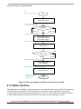
4.3.2 Application data flow overview
The application software is interrupt driven running in real time. There is one periodic interrupt service
routine associated with the ADC end of sequence interrupt, executing all motor control tasks. These
include both fast current and slow speed loop control. All tasks are performed in an order described by
the application state machine shown in Figure 13, and application flowcharts shown in Figure 11 and
Figurw 12.
3-phase Sensorless PMSM Motor Control Kit with MagniV MC9S12ZVM Application Note Rev. 0 05/2015
16
Freescale Semiconductor, Inc.
Software implementation on the MC9S12ZVML128
MAIN
All peripherals required by the
application are reset and configured
Application peripherals
reset & configuration
Initial state machine settings
state = init;
event = e_init;
Enable external interrupts
Enable Interrupts;
FreeMASTER polling function
FMSTR_Poll();
true
while(1)
false
END
Figure 11. Flow chart diagram of main function with background loop.
To achieve precise and deterministic sampling of analog quantities and to execute all necessary motor
control calculations, the state machine functions are called within a periodic interrupt service routine.
Hence in order to actually call state machine functions the periphery causing this periodic interrupt must
be properly configured and the interrupt enabled. As is described in section MCS12ZVM Device
initialization, all peripherals are initially configured and all interrupts are enabled after a RESET of the
device. As soon as interrupts are enabled and all peripheries are correctly configured, the state machine
functions are called from the ADC end of sequence interrupt service routine. The background loop
handles non-critical timing tasks, such as the FreeMASTER communication polling.
3-phase Sensorless PMSM Motor Control Kit with MagniV MC9S12ZVM Application Note Rev. 0 05/2015
Freescale Semiconductor, Inc.
17
Software implementation on the MC9S12ZVML128
/* PMF Reload interrupt service routine
ADC end of sequence
interrupt service routine
ISR
Read HW user controls;
/* User accessible switch
for stopping application
switchAppOnOff or
btFlipFlop
e_app_off
e_app_on
/* State variable acquisition
Meas_Get3PhCurrent();
Meas_GetTemperature();
Meas_GetUdcVoltage();
/* Fault detection routine
faultDetection();
true
faultIDp = 0x0
false
e_fault
/* State Machine periodical calling
state_table[state][event] ();
state_LED[state]();
/* FreeMASTER recorder function
FMSTR_Recorder();
Clear ADC
of
/* Clear
PMFend
Reload
sequence
interrupt
interrupt flag
service flag
RTFI
Figure 12. Flow chart diagram of periodic interrupt service routine.
4.3.3 State machine
The application state machine is implemented using a two-dimensional array of pointers to the functions
variable called state_table[][](). The first parameter describes the current application event, and the
second parameter describes the actual application state. These two parameters select a particular pointer
to state machine function, which causes a function call whenever state_table[][]() is called.
3-phase Sensorless PMSM Motor Control Kit with MagniV MC9S12ZVM Application Note Rev. 0 05/2015
18
Freescale Semiconductor, Inc.
Software implementation on the MC9S12ZVML128
Power on / hw. reset
/* Disable all external interrupts
Application peripherals
reset & configuration
/* Enable external interrupts
executed in ISR
e_init
e_init_done
e_app_off
INIT
e_app_off
READY
e_fault
e_ready
e_fault_clear
e_faul
t
e_app_off
RUN
e_fault
e_run
FAULT
e_app_on
e_align_done
e_fault
e_fault
CALIB
e_fault
ALIGN
e_calib_done
e_calib
e_align
Figure 13. Application state machine
The application state machine consists of following seven states, which are selected using variable state
defined as:
AppStates:
INIT - state = 0
FAULT - state = 1
READY - state = 2
CALIB - state = 3
ALIGN - state = 4
RUN - state = 5
3-phase Sensorless PMSM Motor Control Kit with MagniV MC9S12ZVM Application Note Rev. 0 05/2015
Freescale Semiconductor, Inc.
19
Software implementation on the MC9S12ZVML128
To signalize/initiate a change of state, eleven events are defined, and are selected using variable event
defined as:
AppEvents:
e_fault - event = 0
e_fault_clear - event = 1
e_init - event = 2
e_init_done - event = 3
e_ready - event = 4
e_app_on - event = 5
e_app_off - event = 11
e_calib - event = 6
e_calib_done - event = 7
e_align - event = 8
e_align_done - event = 9
e_run - event = 10
4.3.3.1
State – FAULT
e_fault
FAULT
e_fault_clear
e_fault
Figure 14. FAULT state with transitions
The application goes immediately to this state when a fault is detected. The system allows all states to
pass into the FAULT state by seting event = e_fault. State FAULT is a state that allows transition back
to itself if a fault is present in the system and the user does not request clearing of fault flags. There are
two different variables to signal fault occurrence in the application. The warning register tempfaults
represents the current state of the fault pin/variable to warn the user that the system is getting close to its
critical operation. And the fault register permfaults represents a fault flag, which is set and put the
application immediately to fault state. Even if the actual fault is reset (fault source disappears), the fault
remains set until manually cleared by the user. Such mechanisms allow for stopping the application and
analyzing the cause of failure, even if the fault was caused by a short glitch on monitored pins/variables.
State FAULT can only be left when application variable switchFaultClear is manually set to true (using
FreeMASTER) or by simultaneously pressing the user buttons (SW1 and SW2) on the S12ZVM
evaluation board. That is, the user has acknowledged that the fault source has been removed and the
application can be restarted. When the user sets switchFaultClear = true; the following sequence is
automatically executed:
3-phase Sensorless PMSM Motor Control Kit with MagniV MC9S12ZVM Application Note Rev. 0 05/2015
20
Freescale Semiconductor, Inc.
Software implementation on the MC9S12ZVML128
permFaults.mcu.R
= 0x0;
permFaults.motor.R
= 0x0;
permFaults.stateMachine.R = 0x0;
// Clear mcu faults
// Clear motor faults
// Clear state machine faults
// When all Faults cleared prepare for
cntrState.usrControl.readFault
cntrState.usrControl.switchFaultClear
cntrState.event
transition to next state.
= true;
= false;
= e_fault_clear;
Setting event to event = e_fault_clear while in FAULT state represents a new request to proceed to INIT
state. This request is purely user action and does not depend on actual fault status. In other words, it is
up to the user to decide when to set switchFaultClear true). However, according to the interrupt data
flow diagram shown in Figure 11, function faultDetection() is called before state machine function
state_table[event][state](). Therefore, all faults will be checked again and if there is any fault condition
remaining in the system, the respective bits in permFaults and tempFaults variables will be set. As a
consequence of permFaults not equal to zero, function faultDetection() will modify the application event
from e_fault_clear back to e_fault, which means jump to fall state when state machine function
state_table[event][state]() is called. Hence, INIT state will not be entered even though the user tried to
clear the fault flags using switchFaultClear. When the next state (INIT) is entered, all fault bits are
cleared, which means no fault is detected (permFaults = 0x0) and application variable switchFaultClear
is manually set to true.
The application is scanning for following system warnings and errors:
Over voltage
Under voltage
Over phase current in each phase
Over heating
The thresholds against the measured system variables are compared can be modified in INIT state.
4.3.3.2
State – INIT
e_init
e_app_off
e_init_done
INIT
Figure 15. NIT state with transitions
State INIT is "one pass" state/function, and can be entered from all states except for READY state,
provided there are no faults detected. All application variables and parameters are initialized in state
INIT.
e_init
Initialization of application variables
e_init_done
Figure 16. Flow chart of state INIT
3-phase Sensorless PMSM Motor Control Kit with MagniV MC9S12ZVM Application Note Rev. 0 05/2015
Freescale Semiconductor, Inc.
21
Software implementation on the MC9S12ZVML128
After the execution of INIT state, the application event is automatically set to event=e_init_done, and
state READY is selected as the next state to enter.
4.3.3.3
State – READY
e_init_done
READY
e_ready
e_app_on
Figure 17. READY state with transitions
In READY state application is waiting for user command to start the motor. The application is released
from waiting mode by releasing the on board user switch or by FreeMASTER interface setting the
variable switchAppOnOff = true (see flow chart in Figure 18).
/* PMF Reload interrupt service routine
ISR
/* ADC end of sequence
interrupt service routine
Read HW user controls;
/* On board HW switch
for stopping application
btFlipFlop
e_init_done
e_app_off
e_app_on
state = ready;
event = e_ready;
/* User accessible switch
for stopping application
e_app_on
switchAppOnOff
e_app_off
e_app_on
/* State variable acquisition
Meas_Get3PhCurrent();
Meas_GetTemperature();
Meas_GetUdcVoltage();
/* Fault detection routine
faultDetection();
Figure 18. Flow chart of state READY
4.3.3.4
State – CALIB
e_app_on
CALIB
e_calib
e_app_off
e_calib_done
Figure 19. CALIB state with transitions
3-phase Sensorless PMSM Motor Control Kit with MagniV MC9S12ZVM Application Note Rev. 0 05/2015
22
Freescale Semiconductor, Inc.
Software implementation on the MC9S12ZVML128
In this state, ADC DC offset calibration is performed. Once the state machine enters CALIB state, all
PWM output are enabled. Calibration of the DC offset is achieved by generating 50% duty-cycle on the
PWM outputs, and taking several measurements of all configured ADC channels. These measurements
are then averaged, and the average value for each channel is stored. This value will be subtracted from
the measured value when in normal operation. This way the half range DC offset, caused by voltage
shift of 2.5V in conditional circuitry (see Figure 5), is removed in both measured phases. State CALIB is
a state that allows transition back to itself, provided no faults are present, the user does not request stop
of the application (by switchAppOnOff=true), and the calibration process has not finished. The number
of samples for averaging is set by default to 2^8=256, and can be modified in the state INIT. After all
256 samples have been taken and the averaged values successfully saved, the application event is
automatically set to event=e_calib_done and state machine can proceed to state ALIGN (see flow chart
in Figure 20).
true
calibInitDone
e_app_on
state = calib;
event = e_calib;
Initializa calibration variables
calibDone
= 0;
calibInitDone = 1;
ADC0
EnableOutput();
+
-
true
calibDone
Meas_CalibCurrentSense();
ADC1
f16PhA.f16Offset =
GDFLIB_FilterMA_F16(f16PhA.raw);
f16PhB.f16Offset =
GDFLIB_FilterMA_F16(f16PhB.raw);
f16PhC.f16Offset =
GDFLIB_FilterMA_F16(f16PhC.raw);
Meas_CalibCurrentSense();
+
-
true
CalibStatus= 0x0
true
calibCntr <= 0x0
false
e_calib_done
false
calibDone
Figure 20. Flow chart of state CALIB
A transition to FAULT state is performed automatically when a fault occurs. A transition to INIT state is
performed by setting the event to event=e_app_off, which is done automatically on falling edge of
switchAppOnOff=false using FreeMASTER.
3-phase Sensorless PMSM Motor Control Kit with MagniV MC9S12ZVM Application Note Rev. 0 05/2015
Freescale Semiconductor, Inc.
23
Software implementation on the MC9S12ZVML128
4.3.3.5
State – ALIGN
e_calib_done
ALIGN
e_align
e_app_off
e_align_done
Figure 21. ALIGN state with transitions
This state shows alignment of the rotor and stator flux vectors to mark zero position. When using a
model based approach for position estimation, the zero position is not known. The zero position is
obtained at ALIGN state, where a DC voltage is applied in phase A for a certain period. This will cause
the rotor to rotate to "align" position, where stator and rotor fluxes are aligned. The rotor position in
which the rotor stabilizes after applying this DC voltage is set as zero position. In order to wait for rotor
to stabilize in an aligned position, a certain time period is selected during which the DC voltage is
constantly applied. The period of time and the amplitude of DC voltage can be modified in INIT state.
Timing is implemented using a software counter that counts from a pre-defined value down to zero.
During this time, the event remains set to event=e_align. When the counter reaches zero, the counter is
reset back to the pre-defined value, and event is automatically set to event=e_align_done. This enables a
transition to RUN state see flow chart in Figure 22.
3-phase Sensorless PMSM Motor Control Kit with MagniV MC9S12ZVM Application Note Rev. 0 05/2015
24
Freescale Semiconductor, Inc.
Software implementation on the MC9S12ZVML128
e_calib_done
state = align;
event = e_align;
EnableOutput();
uDQReq.f16Arg1 = ALIGN_VOLTAGE;
uDQReq.f16Arg2
= FRAC16(0);
thTransform.f16Arg1 = GFLIB_Sin(0);
thTransform.f16Arg2 = GFLIB_Cos(0);
GMCLIB_ParkInv(&uAlBeReq,&thTransform,&uDQReq);
svmSector = GMCLIB_SvmStd(&pwm16),&uAlBeReq);
false
AlignCntr= 0x0
true
ClearVariablesAfterAlign();
Set50%Duty();
SetDutycycle();
e_align_done
Figure 22. Flow chart of state ALIGN
A transition to FAULT state is performed automatically when a fault occurs. Transition to INIT state is
performed by setting the event to event=e_app_off, which is done automatically on falling edge of
switchAppOnOff=false using FreeMASTER.
4.3.3.6
State – RUN
e_align_done
RUN
e_app_off
e_run
Figure 23. RUN state with transitions
In this state, the FOC algorithm is calculated, as described in section PMSM field oriented control.
The control is designed such that the drive might be operated in three modes depending on the source of
the position information:
1. Force mode: The FOC control is based on the generated position (so called open loop position),
also this position is supplied to eBEMF observer in order to initialize its state.
3-phase Sensorless PMSM Motor Control Kit with MagniV MC9S12ZVM Application Note Rev. 0 05/2015
Freescale Semiconductor, Inc.
25
Software implementation on the MC9S12ZVML128
2. Tracking mode: The FOC control is still using the open loop position however the eBEMF
observer is left on its own, meaning that the observer is using its own estimated position and
speed one calculation step delayed.
3. Sensorless mode: Both FOC control and eBEMF observer using estimated position.
The mode might be selected manually or automatically depending on the state of variable pos_mod. The
pos_mod can be modified from FreeMASTER interface. For automatic mode the transition is based on
the threshold value set in INIT state.
Calculation of fast current loop is executed every ADC end of sequence interrupt when in RUN state
while calculation of slow speed loop is executed every Nth ADC end of sequence interrupt. Arbitration
is done using a counter that counts from value N down to zero. When zero is reached, the counter is
reset back to N and slow speed loop calculation is performed. This way, only one interrupt is needed for
both loops and timing of both loops is synchronized. Slow loop calculations are finished before entering
fast loop calculations (see flow chart in Figure 24).
e_align_done
manual
controlMode
state = run;
event = e_run;
automatic
automaticMode();
CalcOpenLoop();
CalcSensorless();
pos_mode
ControlModeSelector();
case force:
Control.thRotEl = OpenLoop.thRotEl;
Control.wRotEl = 0;
Force eBEMF with open loop speed
Force eBEMF with open loop position
speedLoopCntr>=
SPEED_LOOP_C
NTR
false
case tracking:
Control.thRotEl = OpenLoop.thRotEl;
Control.wRotEl = 0;
true
focSlowLoop()
case sensorless:
Control.thRotEl = Sensorless.thRotEl;
Control.wRotEl= Sensorless.wRotEl;
focFastLoop()
Pmf_updateDutycycle_SingleShunt();
e_app_off
Figure 24. Flow chart of state RUN
Figure 25 shows implementation of FOC algorithm and the functions and variables used. As can be seen
from the diagram, position/speed estimation is prepared for eBEMF observer.
A transition to FAULT state is performed automatically when a fault occurs. A transition to INIT state is
performed by setting the event to event=e_app_off, which is done automatically on falling edge of
switchAppOnOff=false using FreeMASTER.
3-phase Sensorless PMSM Motor Control Kit with MagniV MC9S12ZVM Application Note Rev. 0 05/2015
26
Freescale Semiconductor, Inc.
Software implementation on the MC9S12ZVML128
Figure 25. Sensorless FOC implementation
4.3.4 Scaling of Quantities
This application uses a fractional representation for most of the quantities. The fractional arithmetic is
supported by several Freescale devices as well as software.
The N-bit signed fractional format is represented using the 1.[N-1] format (1 sign bit, N-1 fractional
bits). Signed fractional numbers (SF) lie in the following range:
Equation 10
For word and long-word signed fractions, the most negative number that can be represented is –1.0,
whose internal representation is 0x8000 and 0x80000000, respectively. The most positive word is
0x7FFF or 1.0 – 2 ^ -15, and the most positive long-word is 0x7FFFFFFF or 1.0 – 2 ^ - 31.
The following equation shows the relationship between a real and a fractional representation:
Equation 11
3-phase Sensorless PMSM Motor Control Kit with MagniV MC9S12ZVM Application Note Rev. 0 05/2015
Freescale Semiconductor, Inc.
27
Software implementation on the MC9S12ZVML128
where:
• Fractional Value = Fractional representation of quantities [–]
• Real Value = Real quantity in physical units [..]
• Real Quantity Range = Maximum defined quantity value used for scaling in physical units [..]
4.3.4.1
Voltage scale
Voltage scaling results from the sensing circuits of the hardware used; in case of the S12ZVM device
the DC bus voltage is sensed directly on device HD pin. The voltage on HD pin is internally divided by
5 and routed to both adc converters. The ADC converters can measure voltage level from zero to 5V.
This is giving already the maximum measurable voltage of 25V on HD pin. For more details see the
device reference manual available at freescale.com.
Voltage quantities are scaled to the maximum measurable voltage, in this case 25V. The relationship
between real and fractional representations of voltage quantities is:
Equation 12
where:
uFrac = Fractional representation of voltage [-]
uReal = Real voltage quantities in physical units [V]
VOLT_RANGE_MAX = Defined voltage range maximum used for scaling in physical units [V]
In the application, the VOLT_RANGE_MAX value is the maximum measurable DCBus voltage, that is,
VOLT_RANGE_MAX = 25 V. All application voltage variables are scaled in the same way.
4.3.4.2
Current Scaling
Current scaling also results from the sensing circuits of the hardware used. For more details see the
device reference manual and board user manual available at freescale.com.
The relationship between real and fractional representation of current quantities is:
Equation 13
where:
iFrac = Fractional representation of current quantities [-]
iReal = Real current quantities in physical units [A]
CURR_RANGE_MAX = Defined current range maximum used for scaling in physical units[A]
3-phase Sensorless PMSM Motor Control Kit with MagniV MC9S12ZVM Application Note Rev. 0 05/2015
28
Freescale Semiconductor, Inc.
Software implementation on the MC9S12ZVML128
In the application, the CURR_RANGE_MAX value is the maximum measurable current:
CURR_RANGE_MAX = 40 A. All application current variables are scaled in the same way.
NOTE
The current sensing circuit provides measurement of the current in the
range from CURR_MIN = -20A to CURR_MAX = +20A, giving the
voltage for the ADC input ranges from 0 to 5V with 2.5V offset. The
fractional representation of the measured current is then in the range <-0.5,
0.5), while the possible representation of a fractional value is <-1,1).
Therefore, CURR_RANGE_MAX is calculated according to the following
equation:
Equation 14
4.3.4.3
Speed Scaling
Speed quantities are scaled to the defined speed range maximum. The speed range maximum is set
higher than the maximum mechanical speed of the drive. The relationship between real and fractional
representation of speed quantities is:
Equation 15
where:
ωFrac = Fractional representation of speed quantities [-]
ωReal = Real speed quantities in physical units [rpm]
OMEGA_RANGE_MAX = Defined speed range maximum used for scaling in physical units
[rpm]
In the application, the OMEGA_RANGE_MAX value is defined as: OMEGA_RANGE_MAX = 9550
mechanical rpm
4.3.4.4
Position Scaling
The angles, such as rotor position, are represented as 16-bit signed fractional values in the range <–1, 1),
which corresponds to the angle in the range <–π, π). In a 16-bit signed integer value, the angle is
represented as follows:
3-phase Sensorless PMSM Motor Control Kit with MagniV MC9S12ZVM Application Note Rev. 0 05/2015
Freescale Semiconductor, Inc.
29
FreeMASTER user interface
4.3.5 MC Library
The application source code uses the Freescale Motor Control Library for the MC9S12ZVML128
microcontrollers (MC9S12ZVMMCLUG , Math and Motor Control Library for MC9S12ZVML128
User Manual, available at freescale.com). The library contains three independent library blocks: GFLIB,
GDFLIB and GMCLIB. GFLIB includes basic mathematical functions (such as sine, cosine, ramp, and
so on). Advanced filter functions are part of the General Digital Filters Library, and standard motor
control algorithms are part of the General Motor Control Library.
5 FreeMASTER user interface
The FreeMASTER[5] debugging tool is used to control the application and monitor variables during run
time. Communication with the host PC passes via USB. However, because FreeMASTER supports
RS232 communication, there must be a driver for the physical USB interface, CP2102, installed on the
host PC that creates a virtual COM port from the USB. The driver can be installed from
www.silabs.com. The application configures the SCI module of the MC9S12ZVML128 for a
communication speed of 19200bps. Therefore, the FreeMASTER user interface also needs to be
configured respectively.
Warnings status
DC Bus Voltage
measurement
Mechanical speed
indicator
Faults status
Application ON/OFF
switch
Clear faults
Figure 26. FreeMASTER Control Page for controlling the application
All application state machine variables can be seen on the FreeMASTER control page as shown in
Figure 26. Warnings and faults are signaled by a highlighted red color bar with name of the fault source.
3-phase Sensorless PMSM Motor Control Kit with MagniV MC9S12ZVM Application Note Rev. 0 05/2015
30
Freescale Semiconductor, Inc.
References
The warnings are signaled by a round LED-like indicator, which is placed next to the bar with the name
of the fault source. The status of any fault is signaled by highlighting respective indicators. In the
previous figure, for example, there are is no pending fault flag however there is one warning indicated
("Udcb HI" - DC bus voltage is close to its over voltage conditions). That means that the measured
voltage on the DC bus is still higher that the warning limit set in INIT state. If the voltage of DC bus
would increase further up, the system would go to fault state and the “UDC HI” would be red colored. In
this case, the application state FAULT is selected, which is shown by a frame indicator hovering above
FAULT state. After all actual fault sources have been removed, no fault indicators are highlighted. The
pending faults can now be cleared by pressing the green "FAULT CLEAR" button. This will clear all
pending faults and will enable transition of the state machine into INIT and then READY state. After the
application faults have been cleared and the application is in READY state, all variables should be set to
their default values. The application can be started by selecting APP_ON on application On/Off switch,
which is a rocker type of button. Successful selection is indicated by highlighting the ON/OFF button in
pale red.
6 Conclusion
The design described shows the simplicity and efficiency in using the MC9S12ZVML128
microcontroller for Sensorless PMSM motor control, and introduces it as an appropriate candidate for
various low-cost applications in the automotive area.
7 References
MTRCKTSPNZVM128, 3-phase Sensorless PMSM Motor Control Kit with the MagniV
MC9S12ZVM available at freescale.com/AutoMCDevKits
FreeMASTER Run-Time Debugging Tool available at www.freescale.com/FREEMASTER
MC9S12ZVMMCLUG , Math and Motor Control Library for MC9S12ZVML128 User Manula
available at www.freescale.com/AutoMCLib
MC9S12ZVMRMV1, MC9S12ZVM-Family Reference Manual available at www.freescale.com
MC9S12ZVML128 Evaluation Board User Manual available at
www.freescale.com/AutoMCDevKits
MTRCKTSPNZVM128QSG , Quick Start Guide for 3-Phase Sensorless PMSM Kit with MagniV
MC9S12ZVML128 MCU, available at www.freescale.com/AutoMCDevKits
Rashid, M. H. Power Electronics Handbook, 2nd Edition. Academic Press
3-phase Sensorless PMSM Motor Control Kit with MagniV MC9S12ZVM Application Note Rev. 0 05/2015
Freescale Semiconductor, Inc.
31
How to Reach Us:
Home Page:
freescale.com
Web Support:
freescale.com/support
Information in this document is provided solely to enable system and software implementers to
use Freescale products. There are no express or implied copyright licenses granted hereunder to
design or fabricate any integrated circuits based on the information in this document.
Freescale reserves the right to make changes without further notice to any products herein.
Freescale makes no warranty, representation, or guarantee regarding the suitability of its
products for any particular purpose, nor does Freescale assume any liability arising out of the
application or use of any product or circuit, and specifically disclaims any and all liability,
including without limitation consequential or incidental damages. “Typical” parameters that may
be provided in Freescale data sheets and/or specifications can and do vary in different
applications, and actual performance may vary over time. All operating parameters, including
“typicals,” must be validated for each customer application by customer's technical experts.
Freescale does not convey any license under its patent rights nor the rights of others. Freescale
sells products pursuant to standard terms and conditions of sale, which can be found at the
following address: freescale.com/SalesTermsandConditions.
Freescale and the Freescale logo are the trademarks of Freescale Semiconductor, Inc., Reg. U.S.
Pat. & Tm. Off.
MagniV is a trademark of Freescale Semiconductor, Inc. All other product or service names are
the property of their respective owners.
© 2015 Freescale Semiconductor, Inc.
Document Number: AN5135
Rev. 0
05/2015