1
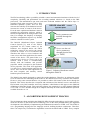
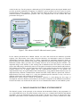
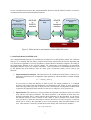
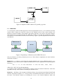
TESLA Report 2005-13
DOOCS environment
for FPGA-based cavity control system
and control algorithms development
Piotr Pucyk, Waldemar Koprek, Paweł Kaleta, Jarosław Szewiński,
Krzysztof T. Poźniak, Tomasz Czarski, Ryszard S.Romaniuk
Warsaw ELHEP Group
Institute of Electronic Systems (ISE), Warsaw University of Technology,
Nowowiejska 15/19, 00-665 Warsaw, Poland
[email protected]
ABSTRACT
The paper describes the concept and realization of the DOOCS control software for FPGAbased TESLA cavity controller and simulator (SIMCON). It bases on universal software
components, created for laboratory purposes and used in MATLAB based control
environment. These modules have been recently adapted to the DOOCS environment to
ensure a unified software to hardware communication model. The presented solution can be
also used as a general platform for control algorithms development. The proposed interfaces
between MATLAB and DOOCS modules allow to check the developed algorithm in the
operation environment before implementation in the FPGA. As the examples two systems
have been presented.
Keywords: Distributed Object Oriented Control System, DOOCS, cavity simulator, cavity controller,
SIMCON, Matlab, FPGA, VHDL, LLRF control system, control software environment,
DOOCS specifics for FPGA systems
Corresponding author: [email protected]
1
DOOCS environment for FPGA-based cavity control system
and control algorithms development
CONTENTS
ABSTRACT ......................................................................................................... 1
1. INTRODUCTION ........................................................................................ 3
2. ALGORITHMS DEVELOPMENT PROCESS ........................................ 3
3. MATLAB-BASED CONTROL ENVIRONMENT .................................. 4
4. DOOCS-BASED CONTROL ENVIRONMENT...................................... 5
5. INTERFACES AND MODULES ............................................................... 6
5.1 MATLAB-DOOCS INTERFACE. .................................................... 7
5.2 DOOCS-HARDWARE INTERFACE. ............................................. 9
6. DOOCS-IMPLEMENTATION .................................................................. 9
6.1 DATA TYPES.................................................................................... 9
6.2 LIBRARIES..................................................................................... 11
6.3 SERVER........................................................................................... 12
7. APPLICATION – SIMULATOR AND CONTROLLER ...................... 13
8. SUMMARY................................................................................................. 17
9. ACKNOWLEDGEMENT ......................................................................... 18
10.
REFERENCES........................................................................................ 18
2
1. INTRODUCTION
The FPGA technology offers a possibility to build a control and automation hardware with the level of
complexity, flexibility and performance far exceeding standard solutions (i.e. based on the DSP
processors). The manufacturers put more and more dedicated modules into the FPGA chips i.e.
complete fixed point processors with a fully
functional operation system. This not only
DOOCS client API - virtual
increases the usability of the hardware but also
operator panel
increases the extent of control of the device.
Even the most sophisticated hardware must be
controlled by appropriate software, which is
flexible enough and can be changed after some
Device parameters are
time. For example, the simplicity of changing
available through the
the FPGA configuration requires very flexible
network
software solution for such a system.
The DOOCS (Distributed Object Oriented
Control System) [1], used in the TESLA
experiment for the remote control of the
hardware was designed before the FPGA
technology started to be used in the control
systems. It consists of a set of libraries and
interfaces that allow to access hardware and
create server and client applications for remote
control of the device. The general idea is to
represent every device as a server seen in the
network. Such a server is communicating
directly with the hardware and provides
properties which correspond to the hardware
device properties. The client GUI application
is in this case a virtual operation panel for this
device. One can run the client application on
the local computer and remotely control
hardware placed in the linac.
DOOCS server – virtual device
Server sets the real
device parameters
through physical bus
(i.e. VME)
HARDWARE
– real device
Figure 1. Scheme of hardware control
through the DOOCS.
The DOOCS was mainly designed to control the existing hardware. Therefore, its architecture seems
to be not sufficient for controlling advanced device like FPGA-based cavity controller and simulator.
However, using some external libraries it is possible to achieve full control of the device through the
DOOCS. This article describes the conception and realization of the DOOCS servers and clients for
FPGA based cavity field controller and cavity simulator, called further in this paper as the SIMCON
(SIMulator-CONtroller) board. This particular software was prepared for a single channel SIMCON
ver.2.0 and 2.1. but is flexible enough to be adapted efficiently for multi-channel SIMCON operation
available from the ver.3.0.
2. ALGORITHMS DEVELOPMENT PROCESS
The development scheme applied in the SIMCON differs from the methodology used in other projects,
which do not base on the on the FPGA technology. One of the main problems during the algorithm
development is the difficulty of implementing the mathematical routines in VHDL code. The VHDL is
not a programming language but the language used for defining hardware architecture. Therefore,
there is no simple way to translate the algorithms created in the MATLAB to VHDL. Every complex
3
algorithm must be tested before the implementation. The changes in VHDL and FPGA, in most cases,
are more complicated than the changes in Matlab or other programming language. Due to this, the
SIMCON and other FPGA-based control board development process can be divided into three main
stages (fig. 2.):
creation
testing
operation
MATLAB
DOOCS
server
FPGA
Figure 2. Algorithm development process.
•
•
•
Algorithm inventing. In this stage, the MATLAB is used as a powerful tool for building
mathematical formulas. The mathematical propriety of the algorithm is being checked. One
can use the offline test signal or access the hardware using dedicated tools to simulate the flow
of the algorithm.
Testing stage is the place where the algorithms are put into the operation environment. The
Matlab functions are compiled into the C functions. These ones are next loaded as a library
into the server. During this stage, one can test the algorithms with a real signal and measure
the influence of the latency of the DOOCS system on the performance of the algorithm. Based
on these tests, one can decide which algorithm parts should be implemented in the FPGA and
which can remain in the software. The testing stage allows starting machine operation with
algorithms running with a decreased speed. This lets the developers to check step by step the
algorithm and move time critical parts into the FPGA without any meaningful influence on the
user interface.
Operation stage is the stage of developing when all algorithms have been tested and the
system is running with a desired performance. In this stage, one can perform further
investigations on the possible algorithms improvement.
The presented scheme shows, that the DOOCS server for the SIMCON should not only be the control
software, but also the environment dedicated to algorithms development. Thus, there exists a
laboratory control system dedicated for creating and testing the algorithms. Some of its modules have
been used in the DOOCS control system. The next paragraph describes the MATLAB-based control
software.
3. MATLAB-BASED CONTROL ENVIRONMENT
SIMCON board is only one of the many FPGA-based projects being realized by Warsaw ELHEP
group [2][3]. During hardware and software development process there is a strong need to have very
flexible tool useful for testing new VHDL code applied in the chip and debugging whole board and its
subsystems. Such a tool should have easy and powerful interface through which one can generate
testing data, access hardware, perform tests, collect and process results. The speed of the system is not
4
critical in this case. For this purpose a dedicated tool [4] for Matlab has been developed. Matlab itself
provides powerful mathematical language. In addition a special toolbox has been created to ensure
communication with the hardware. The most important feature of that system is modular approach to
software-hardware communication problem. The very simplified idea of the solution has been
presented in the figure 3.
Matlab routines
“Read /write“
functions
Matlab toolbox
II Engine library
Unified
interface
Communication
channel
Channel library
SIMCON board
Figure 3. The scheme of MATLAB-based control system.
In the scheme presented above Matlab routines can write and read from the hardware specified
registers, bits and memory areas using read-write functions, and mnemonics names for elements
identification. Inside the toolbox there is a library responsible for translating mnemonics names to
physical addresses of the elements in the FPGA using IID (Internal Interface Description) [4][5]. After
translation another library provides data exchange with the device through physical interface. The
important thing in this solution is, that writing code in Matlab one does not need to care about the
proper data addressing or handle the protocol of the physical interface between Matlab and hardware.
All is hidden inside toolbox. Another important solution is the unified interface between II Engine and
Channel library. For II Engine library the real communication channel is not known. All
implementation issues are again hidden inside channel library. Using unified channel interface one can
implement many different communication channels like EPP, VME, Ethernet, optical link, USB etc.
Both libraries have been written in C, using non platform-specific functions so they can run on
different architectures under different operation systems.
Matlab-based control system created for laboratory purposes is used during the first stage of
development. Since the DOOCS environment is the logical consequent of the Matlab environment it
has been decided to use in DOOCS the same low level communication model as in the Matlab system.
4. DOOCS-BASED CONTROL ENVIRONMENT
The DOOCS system, in the principle, is the skeleton which should be filled by the programmer. In
case of the SIMCON server, the main elements of the server are: communication libraries and Matlab
algorithms. As it was mentioned in the previous chapter, the idea was to move as much of the logic
functions and modules form the Matlab environment as possible. Some of these modules have been
5
ported without any changes, some of them required modifications (especially Matlab code). This
chapter presents the main issues concerning the differences between these two environments.
Moving the algorithms from the Matlab environment into the DOOCS is not only the matter of
compiling the Matlab code. These two environments have different data types, dataflow and the
architecture. The DOOCS server, unlike the Matlab (from the user’s point of view), is a multithreaded
application. This means, that many clients can, at the same time, access the hardware. Since there is
only one physical bus for the hardware, the communication server must contain an arbitrary unit for
the FPGA access. In addition, since the most of logical operations in the FPGA need a sequence of
hardware accesses there must be a mechanism for blocking the access to the device. Figure 4 presents
the model of hardware access used in the Matlab and DOOCS. In the first solution, every Matlab
routine can use, inside its body, functions to access the hardware. Since the Matlab scripts cannot be
run in the multithreaded way, there is a guarantee that one Matlab script will not be interrupted by
another script during the running of the procedure requiring multiple accesses to the device. In the
DOOCS solution, there is an arbitrary unit through which all calls to the hardware should be done. The
compiled Matlab function which is put into the DOOCS server and contains direct calls to the device
is not thread save. It can be called by many clients at the same time, so many instances of this function
will be run at the same time and cause the controller algorithm to crash. This points to the first
requirement: the Matlab routines cannot access the hardware inside the function body. Any data
should be exchange through the function input and output parameters.
Matlab
workspace
Matlab routine
DOOCS server
Compiled
Matlab
routine
Compiled
Matlab
routine
Matlab routine
FPGA
FPGA
Figure 4. Matlab to hardware communication model versus DOOCS to hardware
communication model.
An important issue is also the lack of the Matlab workspace inside the DOOCS server. The compiled
functions cannot use the global variables. The requirements described above can cause some
modification in the Matlab function source code, however, they have no influence on the algorithm
itself.
5. INTERFACES AND MODULES
The DOOCS server is meant to be used as a platform for operation and developing. Therefore, based
on the conclusions drawn in the previous chapter, a number of modules and interfaces have been
defined in the server, in order to adapt the existing libraries into the project as well as to provide
necessary functionality for the compiled algorithms. Figure 5 presents the overall scheme of the
modules and interfaces designed for the SIMCON server. Two main interfaces have been defined, one
6
for the communication between the compiled Matlab functions and the DOOCS and the second for
communication between DOOCS and the hardware.
Matcore wrapper
library
Matcore library
MATLAB
to
DOOCS
interface
DOOCS server
core
compiled
Matlab
functions
DOOCS
to
hardware
interface
Channel bridge
library
II Engine
library
Channel library
FPGA
Figure 5. Main interfaces and modules used in SIMCON server
5.1 MATLAB-DOOCS INTERFACE.
The compiled Matlab functions are available for the DOOCS as a shared library which was called the
Matcore. It is assumed, that one library contains all functions required for the specific algorithm and
only for that one algorithm. For many algorithms, separate libraries should be compiled. According to
the requirements defined in the previous chapter, all connections to the hardware are performed
through the DOOCS server core routines. Therefore, a special interface for all Matlab functions used
by the DOOCS has been defined. There are three types of functions which can be used by the
DOOCS:
•
Input Initialization function. This function must be included inside the Matcore library. It is
needed for initialization of all algorithm input parameters which should be available through
the DOOCS.
A = INPUT_INIT().
It is necessary to name this function as INPUT_INIT. The output parameter A is a Matlab
structure with scalar fields and fieldnames corresponding to the names of input parameters
used in the algorithm (especially in Input function). The DOOCS is using names of these fields
to generate the appropriate data structures in the server (called first order parameters).
•
Input function. This function is used to perform the algorithm calculations which are related
only with the user-input parameters. The input parameter is the Matlab structure from the
function mentioned above, which contains input parameters for the algorithm. As an output,
this function returns a vector of scalars U and a table Y. These variables are so called second
order parameters, which are data ready to load into the FPGA. W is the workspace, a structure
which can be used by the algorithm to store some temporary data (described further in the
text). This structure is shared by all functions in the library and can be freely modified.
[U,Y,W]=FOO(A).
7
•
Internal algorithm function is called by the server and operates on the real data red from the
FPGA. As an output, the function returns table Y with data ready to load into the FPGA. The
function also has access to the workspace W .
[Y,W]=FOO(Y,W).
The interfaces presented above unify the way the DOOCS communicates with the Matlab. The
communication sequence, using the described interface, has been presented in figure 6. During the
initialization of the wrapper library, the INPUT_INIT function is called. It returns the structure needed
for creating in the server a list of properties available in the network. An instance of the matrix A is
created in the wrapper. The user can access its fields through the DOOCS. Next, the INIT function is
called. It uses A structure filled by the user to calculate the U, Y and W parameters. The first two
variables are loaded into the FPGA. W parameter is the local workspace for the compiled functions. It
is not accessible by the DOOCS server. The internal algorithm functions use variable Y and structure
W as the input and output parameters. The wrapper routines take care of updating the temporary tables
only when the functions are going to be called and download results of the calculation back to the
FPGA immediately.
Matcore library
Matcore wrapper
DOOCS server
Used by DOOCS
INPUT_INIT
A
A
Filled by user
(through DOOCS)
INIT
A
U
Loaded to FPGA
U,Y,W
W
FOO_1
FOO_1
FOO_1
Readout from FPGA
Y,W
Y,W
Y
Download to FPGA
Figure 6. The sequence of the library functions calls. The wrapper library stores
temporary tables shared by all functions.
The Y and U parameters correspond to appropriate parameters in the FPGA, so they are fixed to
actual VHDL implementation of the controller. In practice, the Y is a set of control tables (in
current SIMCON 12 tables, from which 8 are read/write tables and 4 are only for reading). Thus,
internal functions use only Y parameter, not Y and U.
The wrapper provides also the thread safety to the Matcore library. During the calculations, all
resources shared by functions are blocked till the running function returns.
8
the
the
the
the
5.2 DOOCS-HARDWARE INTERFACE.
The DOOCS server uses the same compiled versions of IID [5] and channel libraries which are used in
the Matlab based control system. The detailed description of these libraries can be found in [4].
However, there has been a special wrapper library used in order to adapt the non-multithreaded
libraries to the multithreaded DOOCS server.
6. DOOCS-IMPLEMENTATION
The DOOCS server is, in principle, a skeleton of application which has to be filled by the
programmer with appropriate routines and data structures. It should ensure the proper
communication with the hardware and provide the full functionality of the device to the user.
The DOOCS server for the SIMCON is an application in which different environments and
technologies meet together. From one side, there are compiled Matlab functions to C language, which
use specific data types. On the other side, there is an engine for communication with the hardware,
which uses mnemonics names and several data types. In addition, the DOOCS itself contains specific
data structures. All these different environments must work together in a single application. The
DOOCS provides data structures which perform basic RPC network transfer, can represent basic
numerical and char types in the network. The server is a skeleton, which should be filled by the
appropriate routines. This chapter describes specific data types used for the integration of the project
with the DOOCS. It also contains a detailed information concerning the modules and interfaces
implementation presented in the previous chapter.
6.1 DATA TYPES
In the IID format [IID], there are three main data types: BITS, WORD and AREA. According to these
types the appropriate DOOCS equivalents have been created. Every BITS, WORD or AREA can be
accessible through the network using the DOOCS D-classes.
•
•
•
•
D_simcon_bits - is the DOOCS equivalent for BITS type in the II. This class is derived from
D_int class.
D_simcon_reg - is the DOOCS equivalent for WORD type in the II. This class is derived
from D_int class.
D_simcon_area is the DOOCS equivalent for AREA component in the II. It derives from
D_spectrum class
D_simcon_complexarea is a special class dedicated for constructing the amplitude and phase
plots from separate I and Q components (which are mostly D_simcon_area objects). It derives
from D_spectrum class and uses two D_simcon_area object to calculate the amplitude or
phase.
Every class gets in constructor the mnemonic name of the component from II and a pointer to the
Xidd_bridge object (described further in this chapter) which provides access to the hardware. The
methods value() and set_value() have been rewritten, so that they access the given FPGA memory
component using Xiid_bridge. The general scheme of D_simcon classes has been presented in the
figure 7.
9
Figure 7. General UML scheme of D_simcon classes used in SIMCON server.
D_simcon_reg and D_simcon_bits classes use a single command access to the hardware – they are not
thread safe. To update its value table, the D_simcon_area needs to perform the readout from the
FPGA. This requires a consistent set of operations on the FPGA bits and registers. To ensure the
thread safety, the D_simcon_area locks the access to the hardware for the time needed to perform a
complete readout procedure. The current D_simcon_complexarea uses the actual data taken from two
D_simcon_area objects. It does not perform any independent readouts from the FPGA. Therefore,
one must take care of updating the I and Q components of the signal in order to have the proper
amplitude and phase plots. This can be achieved, for example, by putting all 4 plots (I, Q, amplitude
and phase) in the same windows.
In addition, one more DOOCS data type has been created. It is responsible for providing all algorithm
input parameters (first order parameters) in the network. D_matlab_reg derives from the DOOCS
D_float class. Every field from the Maltab INIT structure is represented in the DOOCS as the
D_matlab_reg class.
10
Figure 8. Simplified UML scheme of D_matlab_reg class.
6.2 LIBRARIES
As a consequence of the modular approach to the developed DOOCS server, a set of libraries has been
created. Some of them are exactly the same as in the Matlab version of the control software. All
libraries are directly loaded by the program. This means, that there is no need to copy these libraries
into the directories accessible through LD_LIBRARY_PATH or to modify this environment variable.
The libraries are loaded from the current server directory. Figure 9. presents dependencies between all
used libraries.
libsimcon.so
libvme.so
server
libmatcore.so
libxiid.so
Figure 9. Dependency of libraries used in SIMCON server.
Only two libraries are directly loaded by the server. These libraries implement two main interfaces
described in chapter 5.
libsimcon.so – is a library created from the compiled Matlab code. For the SIMCON software, any
Matlab 6.x version can be used to compile the M-functions. For the compilation, the following option
were used:
mcc –t –L C –W lib:libsimcon –T link:lib foo1, foo2, foo3 …
where foo1, foo2, foo3 are the parameters.
As a product of this compilation a shared library is being created. It contains all functions used in the
algorithm, but only a few of them are called by the DOOCS server.
libmatcore – this library is the wrapper for libsimcon library. It provides the main DOOCS-MATLAB
interface (described in chapter 5.1). It also provides a mechanism that allows to block the access to
the object. The DOOCS routines are blocking the access to the internal libmatcore tables and
11
structures to ensure the data integrity. Different threads in the server could access the libmatcore tables
in the same time. This would cause the failure of the whole controller. Libmatcore separates also the
DOOCS environment from the Matlab environment. In compiled Matlab functions, a sophisticated
interface for communication and data wrapping must be applied. The DOOCS-Matlab interface hides
all Matlab specific data types so that the DOOCS core server source files and Makefile remain
unchanged and can be compiled without access to the Matlab libraries.
libvme - is a small library that provides direct access to the hardware. It is based on the original
DOOCS VME library but has different communication interface. It reads the configuration file located
in the current directory named vme.conf. This file contains three lines:
• VME based address written in hex mode. This is the base address of the SIMCON memory
space mapped in the VME
• The size of the space mapped in the VME.
• The path to the VME device. In this case we are using /dev/24d32 which means that address
has 24 bits and data are 32 bit.
The interface that libvme provides is very simple. There are two functions: one for reading and second
one for writing a 32 bit word under the given address. The important thing about this library is that it
is taken from the Matlab control software without any changes.
libxiid - This library is also taken from the Matlab control environment. This library translates the
mnemonic names into the addresses in the VME space and performs all necessary read/write
operations using libvme library. This library provides interface to the operations which must be thread
safe. Therfore, inside the server it is wrapped with a class which provides the interface for thread
safety. The library reads two configuration files:
•
•
channel.txt - contains the path to the channel library. In this case the channel is VME
and the library is called libvme.
source.txt – contains the filenames of the IID files with description of the FPGA
memory space.
6.3 SERVER
The detailed common DOOCS server structure has been described in DOOCS manual [MANUAL].
The SIMCON server is only the extension of the template server used in many other server
applications in the TTF. This subchapter describes only the SIMCON related issues.
The main server class EqFct_simconserver uses DummyMat class to generate all Matlab-specific
input parameters. All these parameters are of type D_matlab_reg. The server object during
initialization calls INPUT_INIT function from libmatcore library. It returns the structure whose
fieldnames are the names of input parameters to the controller. Based on that, it automatically creates a
list of properties for the server. In addition, the server contains a set of D_simcon_area and
D_simcon_complexarea classes used for the plots. A simplified diagram of the server classes is
presented in figure 10.
12
Figure 10. Simplified UML diagram of additional (non DOOCS) classes used in the server
In the current version of the server, all updates of the input values are made in the step mode. This
means, that after changing any input parameter, this change must be confirmed by pressing a special
button on the panel (see next chapter). This was made for the testing purposes of the current server and
will be changed in the future. To provide this feature, a set of classes has been created based on D_int
class. The integer property reacts to the change of its value and triggers the update procedure.
7. APPLICATION – SIMULATOR AND CONTROLLER
The concept presented in the previous chapters has been used to create two server applications. One is
dedicated for simulator part of the SIMCON and the second one for controller part of the SIMCON. It
has to be mentioned, that both serves are in the very development stage and the description presented
below should be considered as an example of the implementation of the concept presented in the paper
rather than complete application. These applications are to be tested in the operation environment.
The SIMCON controller server DDD panel has been presented in figure 11. It was meant to have the
same functionality as its Matlab equivalent. Therefore, the panel has the same input parameters. The
important thing is, that this version of the server works in the step mode. That means, every change of
any parameter should be confirm by pushing the INIT button which triggers the appropriate functions
to calculate and reload the tables. The RECON button is used to perform a single step of adaptive
FeedForward algorithm.
13
Figure 11. The DDD panel for SIMCON controller server.
Two additional buttons intern mode and extern mode are used to set the controller in the two possible
stages:
• Internal mode – controller drives cavity simulator inside the FPGA. No external inputs are
needed.
• External mode - controller drives the real cavity. All input signal (including clock and trigger)
must be provided.
In practice, during the operation of the SIMCON system, the external mode is used. Internal mode is
used for debugging purposes.
On the DOOCS control panel, there are 4 buttons which run windows with plots. These plots have
been presented in figures below. Every type of signal is presented in 4 plots. Two upper ones are I and
Q components of the signal. Two bottom plots represent amplitude and phase of the signal calculated
from the I and Q components. The current version of these plots is scaled in samples. The final
version will be scaled in MV.
In figures 15 and 16, one can see a control panel and the example readout from the SIMCON
simulator server. The simulator server is running in the continues mode. That means, every change of
any input parameter is automatically applied in the server.
14
Figure 12. I and Q signal on the output of the controller.
Figure 13. I and Q component on the input of the controller.
15
Figure 14. FeedForward tables.
Figure 15. DDD panel of SIMCON simulator server.
16
Figure 16. Plots of the cavity modes calculated inside SIMCON.
8. SUMMARY
The FPGA based electronics for the LLRF control system seems to be the best choice for near future
solutions. It is much faster than commonly used DSP systems, easier to configure and extend. Also the
software, which controls such devices, must be more flexible. Thus, the design emphasis (and amount
of effort) goes from the hardware to the software. The presented solution is an initial proposal for
adapting the existing control system to a new generation of FPGA based hardware. The DOOCS will
for sure be used as the main software environment for operation and the Matlab environment will for
sure be the main development platform. It is essential to combine these two frameworks into one
unified and flexible environment in order to follow the FPGA technology. The described software uses
the same components as in the Matlab control system. It provides all needed data types taken from the
IID in the DOOCS manner.
The presented software project is now in the extremely active testing stage. The final version of the
SIMCON is planned to be finished after detailed tests in the operation environment in the TTF and
FNAL. The future versions of presented solution will control 8 and more channel controller and
simulator and will use newer (version 7.x) Matlab compiled functions. Also, a II-DOOCS diagnostic
module is being developed in order to provides additional features needed for Matlab and VHDL
algorithms development.
17
9. ACKNOWLEDGEMENT
We acknowledge the support of the European Community Research Infrastructure Activity
under the FP6 "Structuring the European Research Area" program (CARE, contract number
RII3-CT-2003-506395)
10. REFERENCES
1.
2.
http://doocs.desy.de
Krzysztof T. Pozniak, Tomasz Czarski, Waldemar Koprek, Ryszard S. Romaniuk - Institute of
Electronic Systems, Warsaw University of Technology, ELHEP Group “DSP Integrated,
Parameterized, FPGA Based Cavity Simulator & Controller for VUV-FEL SC Cavity SIMCON
version 2.1. re. 1, 02.2005 User's Manual “TESLA Report, 2005-02
3. Krzysztof T. Pozniak, Ryszard S. Romaniuk - Institute of Electronic Systems, Warsaw University
of Technology, ELHEP Group; Krzysztof Kierzkowski - Institute of Experimental Physics,
Warsaw “Modular & Reconfigurable Common PCB-Platform of FPGA Based LLRF Control
System for TESLA Test Facility”, TESLA Report 2005-04
4. Waldemar Koprek, Pawel Kaleta, Jaroslaw Szewinski, Krzysztof T. Pozniak, Tomasz Czarski,
Ryszard S. Romaniuk - Institute of Electronic Systems, Warsaw University of Technology,
“Software Layer for FPGA-Based TESLA Cavity Control System (Part I)“, TESLA Report,
2004-10
5. K. T. Pozniak, M. Bartoszek, M. Pietrusinski, "Internal interface for RPC muon trigger
electronics at CMS experiment", Proceedings of SPIE, Bellingham, WA, USA, Vol. 5484, 2004,
pp. 269-282
6. http://www.mathworks.com
7. T. Czarski, R. S. Romaniuk, K. T. Pozniak, S. Simrock: “Cavity digital control testing system by
Simulink step operation method for TESLA linear accelerator and free electron laser”,
Proceedings of SPIE, Bellingham, WA, USA, Vol. 5484, 2004, pp. 88-98
8. T. Czarski, R. S. Romaniuk, K. T. Pozniak, S. Simrock: “Cavity control system: optimization
methods for single cavity driving and envelope detection”, Proceedings of SPIE, Bellingham,
WA, USA, Vol. 5484, 2004, pp. 99-110
9. T. Czarski, R. S. Romaniuk, K. T. Pozniak, S. Simrock: “TESLA cavity modeling and digital
implementation with FPGA technology solution for control system development, Proceedings of
SPIE, Bellingham, WA, USA, Vol. 5484, 2004, pp. 111-129
10. http://www.desy.de
11. http://sun.com
18