1
MASSACHUSETTS INSTITUTE OF TECHNOLOGY
ARTIFICIAL INTELLIGENCE LABORATORY
July, 1987
Working Paper No. 297
The Condor Programmer's Manual - Version II
Sundar Narasimhan
David M. Siegel
Abstract: - This is the CONDOR programmer's manual, that describes the hardware and
software that form the basis of the real-time computational architecture built originally for
the Utah-MIT hand. The architecture has been used successfully to control the hand and
the MIT-Serial Link Direct Drive Arm in the past. A number of such systems are being
built to address the computational needs of other robotics research efforts in and around
the lab. This manual, which is intended primarily for programmers/users of the CONDOR
system, represents our effort at documenting the system so that it can be a generally useful
research tool.
A.I.Lab Working Papers are produced for internal circulation and may contain information
that is, for example, too preliminary or too detailed for formal publication. It is not
intended that they should be considered papers to which reference can be made in the
literature.
Contents
1 Overview and History
2
Introduction
2.1 The Hand Project
............................
3 Hardware
3.1 Design Considerations ..........................
3.2 Components ................................
3.3 The VME-Bus system ..........................
3.3.1 The Ironics IV-3201 Single Board Computer ...........
3.3.2 VM E-Bus .............................
3.3.3
3.3.4
3.3.5
3.3.6
3.3.7
3.3.8
3.3.9
4
Interrupts . .............
Ironics IV-3273 system controller .
HVE Bus to Bus adaptor .....
Memory Board on the VME . . . .
A/D and D/A converter boards..
The Arm Controller Hardware .
The Motorola parallel-port board .
Software
4.1 Introduction and Motivation . . . . . ...........
......
o....
4.2 Roadmap ................
...........
4.3 Level Zero software for the CONDOR
...........
4.3.1 A primer on interaction . ...
4.3.2 Memory management routines ...........
...........
4.3.3 Math routines..........
...
o.......
4.3.4 The I/O Package ........
...........
4.3.5 Strings Library .........
...........
4.3.6 Data Transfer routines .....
...........
4.3.7 Simple Real Time Tasking ...
4.3.8 HVE Libarary - The memory m apped
.. . . connection.
. . . . . . .
4.3.9 Dealing with multiple processor
4.3.10 Command Parser Library - Inpt t routines . . . . .
3
3
4.4
4.5
4.6
4.7
4.8
. .
4.3.10.1 Miscellaneous input routines .........
4.3.11 Window system functions . .................
4.3.11.1 The command parser and X Windows ......
4.3.11.2 Parsing for arguments in the command parser .
4.3.11.3 Window Geometry . ................
4.3.12 Hash Talbles . . . . . . .. . . . . . . . . . . . . . . . . . . .
4.3.13 Buffer ro utines . . . . . . . . . . . . . . . . . . . . . . . .
4.3.14 Tree libreary . . . . . . ... . . ....
. . . . . . . . . ..
....
4.3.15 Small set package ...................
4.3.16 Miscellan eous routines..........................
4.3.17 Internals
4.3.17.1 Interrupts and Vectors . . . . . . . . . . . . . .
4.3.17.2 The interrupt generator . .............
4.3.17.3 The interrupt handler . ..............
Level One Softw'are for the CONDOR . . . . . . . . . . . . . . .
4.4.1 Message Passing Support . .................
4.4.1.1 Introduction
....................
4.4.1.2 M essages ......................
4.4.2 The Sun end . . . . . . . . . . . . . . . . . . . . . . . . .
4.4.2.1 EVH Handler - Mailbox handler on the Sun end
4.4.2.2 How the EVH handler works .........
. .
4.4.2.3 How to use the EVH handler .........
. .
4.4.2.4 List of functions used for message passing . . . .
..
Support for Rea l Time tasks ...................
4.5.1 MOS - A Minimal Operating System . . . . . . . . . . .
Debugging Supp ort...........................
4.6..1
Commands added to GDB . . . . . . . . . . . .
4.6..2
. . . .
Ptrace, Wait, and friends .........
4.6..3
How to use the debugger . ............
4.6.1 Local Dii erences
.........................
4.6.2 Conclusic
Acknowledgemelnts . . . . . . . . . . . . . . . . . . . . . . . . . .
.
•.
.
.. • • , • • • .
.
. .
......
• • • • • • • •...
.
References ...
5 Programs
5.1 CONF .....
5.2 DL68 .......
5.3 ICC . . . . . .
5.4 BURN68....
5.5 RAW......
5.6 MRAW . . . .
5.7 CONDOR. . .
5.8 XPLOT ....
1
A Device Drivers
A.1 Configuration parameters ................
...........
A.2 The devsw structure and the devtab table. ..........
......
A.3 Explanation of the internals ...........................
A.3.1 Init routine ................................
A.3.2 Open routine ...............................
A.3.3 Close routine ...............................
A.3.4 Other standard routines .........................
A.3.5 Support for non-standard routines . ..................
B Hardware configuration
B.1 The Ironics boards ................................
B.2 The HVE Adaptor ................................
96
96
. . 97
99
99
101
103
104
105
107
107
108
Overview and History
The Utah-MIT Hand project was started in the fall of 1983 to build a high performance
dexterous robotic end-effector, capable of human-like performance. The hand itself was
built by the fall of 1985. The first version of the hand was controlled by an earlier incarnation of the hardware and software presented in this document. (This earlier version was
based on Motorola 68000 single-board computers on the Intel Multibus. This version will
be referred to as CONDOR -Version I in this document.)
A redesign of the actuators was completed in the fall of 1986. Coupled with this was a
redesign of the computational architecture, both hardware and software. It is this second
version (known as CONDOR -Version II) that this document describes.
Although the computational architecture was developed originally to control the UtahMIT hand, the architecture that has resulted is a powerful, multi-micro-processor system
that is fairly general in its scope, and is oriented specifically towards real-time computation.
The architecture has been used to control other robotic devices besides the Utah-MIT hand,
notably the MIT serial link direct-drive ARM. There are a number of these systems in the
process of being built at MIT to address the real time needs of other research groups at
MIT's Artificial Intelligence Laboratory. Besides this, a number of research efforts around
the nation (in particular Stanford's NYMPH architecture and a research architecture being
built at IBM) have acknowledged our system's influence on their design.
Introduction
2.1
The Hand Project
The Utah-MIT hand is a pneumatically powered four-fingered hand, built to investigate
issues related to machine dexterity, as part of an ongoing project at the University of Utah's
Center for Engineering Design and M.I.T's Artificial Intelligence Laboratory. Each finger
of the hand has four joints. Each joint is driven by a pair of pneumatic actuators operating
at around 70 psi. The actuator used is an extremely fast, single stage, pressure servo
controlling the position of a graphite piston encased in a glass cylinder. The movement
of a piston is transmitted to the actual joint by tendons routed over pulleys. The hand
is approximately anthropomorphic in size and shape. A more detailed discussion of the
design issues involved can be found in Jacobsen et al. [1985, 1986].
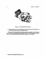
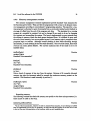
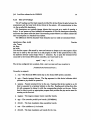
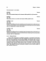
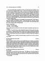
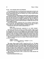
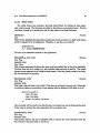
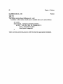
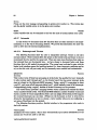
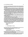
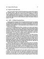
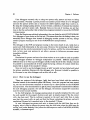
The hand has thus sixteen degrees of freedom in itself (four fingers each with four degrees
of freedom) (see Fig. 2.1). It also has two wrist degrees of freedom to some extent, but
these are not presently actuated. The hand is mounted physically on the arm subsystem,
which comprises of four cartesian degrees of freedom. The hand can be moved up and down
in a vertical direction (the z axis), and horizontally, (the y axis) using this arm. In addition
to these two degrees of freedom, a two degree of freedom z-y table is positioned beneath the
arm bringing the total degrees of freedom of the wrist relative to a fixed absolute reference
frame to four. The actuator assembly (known as the actuator pack) is mounted separately
from the arm subassembly. The tendons from the actuator pack are routed to the hand
via a mechanism known as the remotizer which is essentially a mechanism for mounting
the hand separately from the actuator pack while keeping constant the lengths of all the
tendons even while the hand is moving.
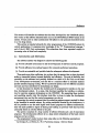
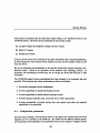
The manual is organised into the following sections.
1. A section on hardware. This section describes briefly, the different components that
comprise the hardware configuration of the CONDOR system.
2. System and application level software support needed for the CONDOR system. Since
this manual is a programmer'smanual, we provide explanations at two levels; one
aimed mainly at a user of the system, and another for a prospective maintainer or
implementor of system software. Some sections intended for the latter group assume
a fairly detailed knowledge of Unix and the C programming language.
Users whose main interest in the computational architecture is to use it to control
the hand ought to read Section 4.3. This section documents the external interface
that the software presents to the application programmer and provides a description
of all the utility libraries.
Chapter 2 Introduction
Figure 2.1: The Utah-MIT dexterous hand
3. Manual pages for the various programs that go into making up the development and
run-time environment that is the CONDOR system.
The version of the system described in this document pertains mostly to the development
environment that runs on the Sun-3 workstations in the Lab. 1 , and the runtime environment
that runs on Motorola 68020 based single board computers on the VME-Bus.
'The Sun-3 is a trademark of Sun Microsystems, Inc.
Hardware
This section discusses the hardware architecture of the CONDOR hand control system.
The purpose of this section is to provide the motivation for some of the design decisions
that were made during the development of the CONDOR system, and to provide some
guidance for installing and maintaining such a system.
3.1
Design Considerations
An early decision was made to use off-the-shelf hardware whenever possible. This decision was motivated by the observation that computations needed to control a general
purpose robotic hand are suitable for general purpose computer architectures, and custommade computer hardware is rarely cost effective when only few systems are to be built.
In addition, keeping a custom built system at the state of the art requires constant improvements in the hardware, and is a never ending proposition. Such a task is best left to
commercial companies that specialize at this.
An initial examination of the types of computations that were expected to be performed
indicated that a multiprocessor based hardware solution would work well. Using multiple
processors is advantageous for several reasons. Most importantly, additional computer
power can be obtained by adding more processors to the system. In addition, alternate
control strategies can be tested simply by partitioning them in different ways. For example,
reprogramming a uniprocessor that controls multiple robots would require much more work,
since many time critical events need to be serviced in a complex fashion.
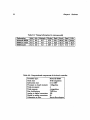
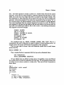
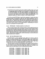
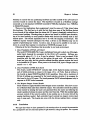
Once the decision to use multi-micro-processors had been made, the individual processor
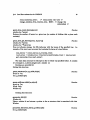
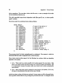
on which the system would be based had to be chosen. Table. 3.1 compares the price to
performance ratio of some of the CPU's available then that were considered. (See also Table.
3.2 which gives benchmark timings for some of the operations on the current configuration).
Table 3.1: Comparisons of processing power available from different hardware configurations.
Processor Type
Microvax II
Vax 11/750
Symbolics 3600
National 32032
Motorola 68000
Speed
1 MIP
1 MIP
1 MIPS
1 MIPS
1 MIPS
Cost
mod
high
high
low
low
Motorola 68020
2.5 MIPS
low
Comments
interconnect problems
interconnect problems
lacks real time support
lacks floating point
Chapter 3 Hardware
In some robotics controllers, the enormous attention paid to efficiency and performance
has often resulted in cryptic, unmaintainable and inextensible systems. Since our system
is to be used primarily as a research tool, it was desirable that it be highly flexible, extensible and portable to other hardware architectures as well. However, at the same time,
performance goals had to be met. These goals were often conflicting, but we felt that by
appropriately organizing the computational hierarchy we would be able to strike the right
balance between them. For a more detailed discussion of the pertinent issues involved see
Siegel et al., [1985] and Narasimhan et al., [1986].
The important features of the CONDOR hardware that are expected to persist across
multiple system configurations are therefore (see Table. 3.3):
1. Powerful multi-micro-processor system. (the individual CPU that the system
is based on may change although at present we strongly rely on the Motorola 680xx
line).
2. Standard interconnect scheme. The present version of the system (i.e. CONDOR
-Version II), is based on the industry standard VME-bus. An earlier version was based
on the Intel Multibus. These high-speed busses form the basis for our inter-processor
communication scheme. Using an industry-standard bus to form the backplane of
our system has the added advantage in that peripherals like A-D/D-A boards, and
digital I/O boards are readily available for such busses as are powerful single-board
computers.
3. Tightly-coupled multi-processor interconnect. The present version of the system and quite a few in the future will be based on the shared dual-port memory
paradigm for interprocessor communication. Although support may be added for
network interfaces, parallel ports etc., these are not expected to be fast enough to
satisfy our real-time constraints which are typical of high-performance robotic controllers.
3.2
Components
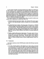
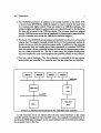
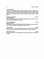
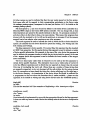
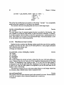
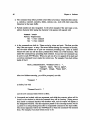
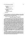
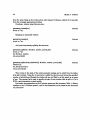
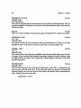
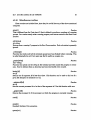
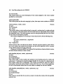
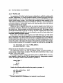
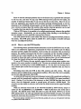
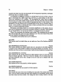
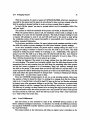
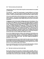
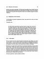
The hardware architecture of the CONDOR system consists of the following components
(see Fig. 3.1);
1. The analog controller subsystem. This subsystem can be used to bring up the hand
in a turn-key mode which is extremely useful in running certain diagnostic tests and
quick demonstrations. It requires very little else to operate and is described in the
document The Utah-MIT dexterous hand - Electronics, and will not be described
further in this document. Users of the CONDOR will rarely use the system in this
mode. This system essentially consists of the box with flashing lights next to the
hand. The more important function played by this box is that it houses and powers
the analog drivers needed to power the hand's electronics. This forms the lowest level
of the hand control system.
§3.2
Components
2. The CONDOR processors. In addition to the analog controller at the lowest level,
a bunch of four MOTOROLA 68020 processors are used to control the hand when
it is running under digital control. These are housed in a VME-Bus cardcage. The
analog-to-digital and digital-to-analog boards, are presently housed on the Multibus,
but they will be moved to the VME-bus shortly. The processor boards are plugged
into the VME-Bus across which data is transferred for interprocessor communication.
A-D/D-A transfers occur across the VME-Bus to Multibus adaptor.
3. The Sun-3. The CONDOR microprocessors are interfaced to a Sun-3 via a bus-to-bus
adaptor link. The adaptor basically extends the bus on the development machine to
include the bus on which the control processors reside. In addition to this extremely
fast connection that can transfer data at rates comparable to a standard VME-Bus,
there also exists a slower connection between the Sun and the microprocessor subsystem via a 9600 baud serial line. The Sun is used mainly for program development.
The user interface for most control programs also presently resides on this machine.
4. The Arm control hardware. The Arm subsystem is controlled by Slo syn stepper
motors which are controlled by a controller card that also plugs into the Multibus.
M68020
M68020
II
M68020
I
M68020
VME-BUS
Figure
3.1:
Hardware
block
diarram for thee...Utah-MIT
hand
controller.
Fifur
3 1:. Hardware..oc..
.
.
..........
...
............
ntrolle
In this document, we do not discuss either the arm control hardware or the analog
controller hardware designed for the Utah-MIT hand. Our emphasis will primarily be on
the Motorola 68020 system designed to run control software and the development software
that presently runs on the Sun.
Chapter 3
3.3
3.3.1
Hardware
The VME-Bus system
The Ironics IV-3201 Single Board Computer
This processor board forms the main workhorse of the multi-micro-processor controller
hardware. The Ironics IV-3201 Processor board is a powerful single-board computer based
on the Motorola 68020 microprocessor, coupled with the fast 68881 floating-point unit. In
addition to the microprocessor, many other functions are provided on-board as described
below.
An industry-standard 28-pin byte-wide memory socket is provided to hold a PROM
which contains up to 32 Kbytes. This prom is used to provide the monitor which bootstraps
user programs.
The board contains one megabyte of RAM, which may be expanded to a total of four
megabytes if desired. This no wait-state, dead-lock protected RAM is dual-ported; i.e it
may be accessed either locally by the processor, or as a VME-Bus Slave by another device.
Memory base addresses may be jumpered to start at any of a set of predefined locations.
It is necessary that the dual port address of every board in a system be configured correctly
for the software to operate correctly (see Appendix B, for this configuration information).
The Ironics single board computer is adequately described in the document titled IV3201 68020 CPU Board - User's Guide, which is available from Ironics, Inc. Please refer to
this document for further information regarding the features it has, and for board-specific
configuration information.
3.3.2
VME-Bus
The individual ironics cpu boards are all plugged into the industry standard VME-Bus
backplane. More documentation on the VME-Bus can be found in the document titled The
VME-Bus specification manual which is available from a number of manufacturers. This
document is also known as the IEC 821 Bus and the IEEE P1014/D1.0.
The VME-bus specification provides for a variety of options. The version of the backplane we use in our system is based on the J1-J2 two-high connectors each of which are 96
pins.
The bus specification includes provisions for data transfer, interrupts and bus arbitration. It specifies a bus that has 32 bits of address and data and 5 bits (or 32 values) for
address modifier codes. This enables address cycles on the bus to be further distinguishable
by the code that is passed on the modifier lines, and obviates the need for specialized i/o
spaces.
The VME-Bus'es different address spaces are mapped into separate blocks of the full 32
bit address space on the Ironics 3201 processor board. Please see the document titled IV3201 68020 CPU Board available from Ironics, for the particular mapping that is currently
available from them.
The VME-Bus provides for 4 different levels of bus requests and grants. We have chosen
to put all the Ironics cpu boards at bus request level 3 (BR3). The synergist-3 type of
bus-to-bus adaptor is configured to run at level 2 (BR2) while the hve-2000 type of adaptor
is configured to run at level 3 (BR3).
§3.3
The VME-Bus system
Please see the section below, for information pertaining to VME-Bus interrupts.
The bus arbitration on the VME-Bus we presently rely on the system controller functions performed by the IV-3273 system controller available from Ironics. We do not use the
system controller available on the HVE bus to bus adaptor which must be disabled on the
slave VME-Bus, for proper operation on the CONDOR system.
3.3.3
Interrupts
The VME-Bus supports vectored interrupts. The basic idea is that an interrupting
device raises an appropriate interrupt request line to indicate that it wishes to interrupt
a processor. The VME-Bus supports eight levels of interrupt priority. The device that
wishes to service the interrupt is known as the interrupt handler. When this device senses
that a peripheral wants to interrupt the processor, it acknowledges the interrupt, starting
an IA CK cycle. The peripheral is supposed to place a vector number on the data bus
when it receives the interrupt acknowledge signal. The vector number indicates to the
processor the routine that it must execute in response to the requested interrupt. For a
detailed explanation of the signal transitions during this entire process, see the VMEBus
Specification Manual. For an explanation of how processor vectors work, see the Motorola
68020 User's Manual. Please see Section 4.3.17.1 for programming information regarding
interrupt vectors.
Each of the Ironics 3201 boards has an interrupt handler chip that can be programmed
to respond to any of the eight VME-Bus interrupt levels, or any of eight local onboard
interrupt sources. Please refer to the Ironies 8301 User's Manual and the Motorola 68155
Interrupt Handler - Data sheets for further information on this interrupt handler chip.
3.3.4
Ironics IV-3273 system controller
The Ironics IV-3273 system controller board performs the important function of arbitrating bus requests on the slave VME-Bus. This board also has a number of devices like
a serial io device, a parallel port device etc., on it, that can be used by the 3201 processor boards. For further information on this controller board, please refer to The Ironies
IV-3273 System Controller - User's Guide available from Ironics.
This board's serial io chip (the Motorola M68681) forms the terminal driver of our
system. Please see Page 23 for programming details concerning hardware devices, and
Appendix A for details on how to write a device driver for a new device that is to be
incorporated into the system. This serial driver is needed only for initial bootstrapping
and debugging operations. Since the serial chip on the ironics system controller card can
be controlled only by one processor at a time, forcing all processors' terminal i/o through
this single serial chip is hopelessly cumbersome. To overcome this problem we have designed
a pseudo terminal emulator which the processors can use to communicate with the Sun over
the bus-to-bus adaptor. This psedo terminal emulator or pty is designed as a service to
work on top of the message passing system which will be described later.
Chapter 3
3.3.5
Hardware
HVE Bus to Bus adaptor
The Hal Versa Engineering board connects the slave VME-Bus on which the Ironics
single board computers are mounted to the VME-Bus that houses the Sun-3. Physically
this subsystem consists of two boards connected together by two cables. While one board
is plugged into the Sun-VME backplane the other is designed to plug into the slave VME
system.
There are two versions of the hve adaptor that are currently in use. The first version,
called the synergist-3 is a 16-bit device while the second called the hve-2000 is a fullfledged 32 bit device that connects up the two vme-busses in a completely transparent
fashion.
The synergist-3 version of the adaptor provides i/o locations that the users can write to
on either side of the bus. These i/o locations when written to, cause dynamic connection
or disconnection of the bus-to-bus adaptor. For the CONDOR software system to function
correctly, these i/o locations must be configured correctly. (Please see Section B for details).
For programming details on how to use the bus-to-bus adaptor system from the Sun
please see Section 4.3.8. For programming details on how to use the mailbox communication
mechanism to communicate to the Sun from the microprocessors see Section 4.4.1.1.
The bus-to-bus adaptor in addition to providing a fast and transparent memory-tomemory link also provides a way of mapping interrupts from the Ironics processors to
the Sun CPU. To accomplish this purpose we have left ONE interrupt level (level one)
connected between the two busses. The other interrupt levels are disconnected to prevent
unwanted interaction between the Sun's Operating system and interrupting devices on the
slave vme bus. The sun initiates communication with the ironics processors by using the
mailbox interrupt present on the processor boards while the ironics processors use this single
interrupt level to interrupt the sun across the bus-to-bus adaptor in order to communicate
with it.
3.3.6
Memory Board on the VME
The message passing system requires each processor to have a section of memory devoted
primarily for message passing. While it is easy to get such memory on the CONDOR
processors, getting such memory from the Sun end may not be such an easy task. Rather
than use Sun's DVMA space or other solutions that were not very appealing, we chose to
augment the slave VME-Bus with an extra 1Megabyte memory board intended solely for
use by the Sun.
Any commercially available memory board will do the task. We recommend the MVME204 board made by Motorola. This board is available in two flavors - the MVME-204-1 is
a one megabyte board, while the MVME-204-2 is a 2 megabyte memory board.
If adding such a board would not be possible owing to other constraints, the software
can be reconfigured and recompiled so that a small portion of memory from an Ironics
processor board can be used by the sun for this purpose.
§3.3
3.3.7
The VME-Bus system
A/D and D/A converter boards
A variety of analog-to-digital and digital-to-analog converter boards are available offthe-shelf for the VMEBus. In this section we describe the boards made by Data Translation,
that are the ones currently being used by the CONDOR controller for its data acquisition
operations. (Users intending to use the system present in MIT's AI Laboratory should refer
to Section 4.6.1).
There are a number of features that one ought to watch out for in picking data acquisition hardware. Primary considerations are speed, number of channels and number of bits
of resolution provided by the board. Other factors that merit evaluation are programmable
gain, interrupt capability and protection circuitry.
1. Data Translation A/D Boards: The A/D board that we recommend for the CONDOR system is a device that has 32 single ended channels each at 12-bits of resolution.
The board is made by Data Translation and its product number is DT-1401. It has
a programmable gain option and provides interrupting capability. For programming
details on data acquisition hardware see Section 4.3.6.
2. Data Translation D/A Boards: The DT1406 D/A board made by Data Translation
complements the A/D board effectively. It provides 8, 12 bit channels, intended for
voltage output. Besides multiplying DAC's the board also has a DC/DC converter
for noise reduction.
3.3.8
The Arm Controller Hardware
The arm controller hardware is based on the Magnon stepper-motor controller on the
Multibus. Since this is also a feature peculiar to our local environment, documentation on
this is deferred to a later section. Programmers interested in using this system should refer
to Section 4.6.1 for details.
3.3.9
The Motorola parallel-port board
In our system the capability for parallel i/o is provided by the Motorola MVME-340
parallel port board. This board is based on the Motorola 68230 Programmable parallel
port and Timer chip.
The versatility of this chip, and consequently that of the board makes it impossible to
describe it adequately in this document. For further documentation on the chip and the
board please see the document titled MVME-840 - User's manual available from Motorola.
Chapter3
Hardware
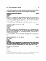
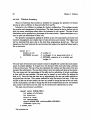
Table 3.2: Timing Information (in microseconds)
Explanation
Motorola 68000
68020/no cache
68020/cache
Add
5.2
6.2
4.0
Sub
6.0
5.6
2.9
Multiply
8.2
6.3
4.0
Divide
57.0
41.0
26.7
Fadd
170.1
32.4
24.7
Fsub
190.0
32.4
24.8
Fmul
275.7
40.8
31.5
Table 3.3: Computational components of the hand controller.
Processor type:
Clock rate:
Instruction rate:
Processor on board memory:
Total processors:
Total memory:
Bus Architecture:
Analog to digital converters:
Digital to analog converters:
Connection to Sun:
Motorola 68020
16-25 megahertz
r 2.5 MIP
1 Megabyte
4
4 megabytes
VME-bus
128
32
Bus-to-Bus adaptor
Fdiv
642.2
42.3
35.0
Software
This section will describe the software that has been developed for the CONDOR system.
The version of the software described here runs on the MOTOROLA 68020 version of the
system. Future ports to other architectures will adhere to the protocols described herein
to a very large extent.
This section is intended primarily for other programmers of the CONDOR system for
control applications; It presumes prior knowledge of the "C" Programming Language I
and of the 4.2 BSD Unix environment; The subsections have been organized roughly in
increasing order of detail and complexity.
4.1
Introduction and Motivation
The software system was designed to achieve the following goals:
(a) Provide a flexible environment to aid the development of real-time control programs.
(b) Provide efficient, low-overhead support for commonly performed operations.
(c) Provide an extensible and portable basis for subsequent software development.
These goals were often conflicting, but we hope that the system that we have developed
strikes a reasonable balance between flexibility and efficiency. The goal of flexibility and
portability at the software level partially dictated our choice of C and Unix as the basis
of our development environment, and also led to a conscious effort to minimize machine
specific assembly language coding. We have ported the system onto two different machines
and each port has contributed to streamlining our design.
In this document we describe the modules and the programmer's interface to the real
time development system. In a sense, this document specifies the interface or architecture for real-time program development on the CONDOR . By separating these modules
and specifying exactly what this interface looks like, we hope to make the development
environment into one that the control programmer can rely on.
Separating the control programs from the underlying system support required for them
is also beneficial in another respect. By writing emulation libraries for the architecture, it
will be possible to run the same higher level control programs on different architectures.
This will make possible a degree of sharing and building on previous work that has been
noticeably absent in robotics efforts in the past.
The system comprises of a large number of software libraries and a set of stand-alone
programs. The development software is to a large extent independent of the hand control
programs we have written.
The programmer's model we have been using relies on the following assumptions:
1see Kernighan B., and Ritchie, D., The C ProgrammingLanguage - Reference Manual
Chapter4
Software
* All control programs will be written in C on the development machine.
* These programs are intended to be run on one or more processors comprising the
CONDOR hardware.
* The programs are compiled and downloaded to the individual microprocessors to be
actually run.
* The programs are then run and debugged on the slave microprocessors.
The software system has therefore been designed to provide support for the following:
(a) Provide C startup and runtime support on the bare machine.
(b) Provide facilities for interprocessor communication.
(c) Provide support for debugging in this environment.
Besides the above, the system provides support for adding new hardware devices into
the base sytem, for user level scheduling of real-time tasks and managing timers, for file
system operations on the slave microprocessors and a host of other often needed system
functions.
4.2
Roadmap
The following section is intended to provide a brief overview of what the various facilities
are, and where the source for them can be located.
1. ./condor - The top level source directory.
2. ./bin - Directory for binary executables, utilities etc.
3. ./include - Directory for include files.
4. ./include/vme - Directory for include files specific to the VME port.
5. ./hand - Hand control programs.
6. ./lib
- Directory where libraries are kept.
The source directory has the following subdirectories.
1. ./condor/boot - Source for creating boot proms. Not needed for Version II of the
hardware.
2. ./condor/cmd - Source for standalone utilities.
3. ./condor/ddt - Source for the obsolete Stanford debugger system.
4. ./condor/diag - Various diagnostic programs.
§4.2 Roadmap
5. ./condor/doc - Documentation.
6. ./condor/libc/crt - C runtime support routines.
7. ./condor/libc/csu - C startup support.
8. ./condor/libc/dev - Device independent file descriptor routines.
9. ./condor/libc/ironics - Ironics port code.
10. ./condor/libc/libsun - Support code that runs on the Suns.
11. ./condor/libc/microbar - Microbar port code.
12. ./condor/libc/stdio - Stdio support code.
13. ./condor/libc/strings - Strings library.
14. ./condor/libc/sun - 020 specific code that is different from the sun supported
library code.
15. ./condor/libc/test - Testing and validation programs.
16. ./condor/libc/unix - Miscellaneous Unix support routines.
17. ./condor/libc/vmedev - Device drivers for various VME boards.
18. ./condor/libutils/math - Utility math library source.
19. ./condor/libutils/parser - Command parser library source.
20. ./condor/libutils/xwindows - X window system support library.
Individual files, will be mentioned by name later on in the document, as and when
required.
Chapter4
4.3
Software
Level Zero software for the CONDOR
This section will summarize briefly, what software is currently available for doing realtime programming, on the CONDOR system, at the uni-processor level. In particular, this
section covers information on the math, stdio and interrupt management library routines.
These sections cover programmer libraries that are used often. The more complex facilities for message-passing based inter processor communication and the MOS (the Minimal
Operating System) are deferred to the section which follows. Documentation is provided
only for those functions that are completely new in our system or whose semantics deviate
sufficiently from their normal interpretation in the Unix Programmer's manual. (For example, no documentation is provided here, on standard functions like printf, sin or malloc,
besides mentioning their names to indicate that they are supported). This section, along
with the standard I/O documentation commonly found in the Unix Programmer's manual,
should provide the user with the capability of writing simple control programs that run on
one processor of the CONDOR system.
The functions are documented in terms of the modules they appear in, in no particular
order. A fully alphabetical index for all the functions appears at the end of this document
to enable users to locate the documentation associated with a particular function more
readily.
It should be also mentioned that in this document we do not provide any documentation
on how to write hand control programs, or documentation on the hand control programs
that are currently available. Such documentation will be deferred to another document
that will be published in the future.
J4.3 Level Zero software for the CONDOR
4.3.1
A primer on interaction
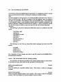
In this section, we describe, how a simple program can be downloaded and run on the
micros. It is provided primarily for illustration. The example does not use the sophisticated
window based user interface program and hence will be quite easy to understand. By
following the example, one can get a feel for what is involved in actually running a simple
program on the slave microprocessor. We hope that the example helps a prospective user
get on and use the system in an extremely short period of time.
1. Make sure that the hardware is plugged in, and everything is configured correctly.
(Refer to Section B for details on configuration, if you haven't already).
2. Power the slave VME first before powering up the sun. This should cause the green
led on the front panel of the Ironics processors to light up. Now power up and boot
the Sun to run Unix as usual.
3. The program raw can be used to connect up directly to the Ironics's serial line, using
the Serial port on the Sun. When you execute this program, with the serial line
connecting the serial port on your sun to the ironics serial port, the Ironics boot
prom monitor (called IMON) should appear on your terminal.
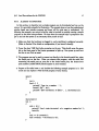
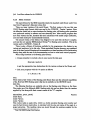
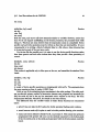
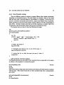
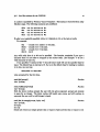
4. Prepare a file called test. c and include the following example program in it. (Of
course you can replace it with the first program of your choice).
main()
{
int i;
for(;;) {
printf('"Type in a number: ');
scanf('•d",
ki);
printf(' 'd's factorial is %d\n'', i. factorial(i));
}
factorial(i)
int i;
{
if(i < 0) {
printf(''Can't take factorial of a negative numberl\n'');
exit(O);
}
if(i -= 0) return(l);
else return(i * factorial(i-1));
Chapter4 Software
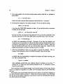
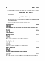
5. Now cross-compile it for the slave microprocessor system using the icc program as
given below.
icc -o test.68 test.c
Notice that this command takes arguments exactly like the cc command.
6. Download the program to the ironics processor. You can do this by typing
d168 -p 0 test.68
if you have the VME-VME connection in place. If you dont have such a connection
in place yet, you can type
d168 -p - -sd /dev/ttyb test.68
For this to work, you must have the serial port 'B' on your Sun connected to the
alternate serial port on the Ironics 3273 system controller board. Now if you type
LO ; "Downloading:
"
at IMON the downloading will begin. Obviously, if you have two windows, one
connected up to the processor via raw and the other running a simple shell the above
procedure is quite simple to do, and its results will be easier to observe. Make sure
that the alternate serial port is set up correctly before doing this. (Please see the
IMON documentation on the IO command on how to do this).
7. After the downloading is done, you are ready to execute the program. The icc
program links programs to start at Oxl0000 by default. Hence if one types
GO 10000
at IMON after the downloading is complete the program will begin executing, and
you will be prompted with:
Type in a number:
After satisfying yourself that your program indeed is working, you can type ""
followed by 'q' (that is the tilde character followed by the 'q' character) to return
from the raw program.
That concludes our first simple example. As an exercise, figure out how many bits are
there in an integer as compiled by icc (Hint: Use the program that you just downloaded
and ran).
The program mraw and the shell script arun can be used to run the above program on
any other processor besides processor 0. Notice that the same program runs identically
over the bus to bus adaptor using pty's and mraw as it does over the serial line using the
tty driver and the raw program.
§4.3 Level Zero software for the CONDOR
4.3.2
Memory management routines
The memory management routines implemented provide standard Unix semantics for
the functions given below. They provide the programmer with a way to do dynamic memory management according to conventional C programming practice. The stack for a running program is allocated to grow downwards from a previously decided point (defined in
storage. h) offset from the end of the program and data.
The stacksize for a running
program is a compiled in constant, but can be changed if one needs to do so, by changing
the constant and recompiling the system. The heap is implemented to grow upwards from
the address in memory where the stack grows downward from. It is defined to grow until
the end of local memory, but not anywhere beyond. Local memory size is computed when
programs begin to execute. Although bounds checking is done while allocating storage
dynamically, no such checking is done for stack allocation. This of course means, that stack
overruns can mean global disaster. The current maximum size of the stack is set to be
Ox20000 bytes.
malloc(bytes)
unsigned bytes;
Standard Unix semantics.2
Function
free(ptr)
char *ptr;
Standard Unix semantics.
Function
sbrk(incr)
Function
int incr;
Gets a chunk of memory of size incr from the system. Returns nil if currently allocated
memory size plus the increment asked for exceeds the maximum memory present on the
machine. This function is used internally by malloc ().
realloc(ptr, bytes)
char *ptr;
unsigned bytes;
Standard Unix semantics.
Function
Examining memory:
The following routines that deal with memory are specific to the slave microprocessors (i.e.
these cannot be used on the Sun).
memory peekc(address)
Function
2
In all of the documentation, whenever we refer to standardUnix semantics, we are referring to 4.2BSD
Unix as implemented by Sun's O.S. In particular, we mean that the man program on the Sun can be used
to find out the exact documentation on the functions, which we omit repeating here.
Chapter 4 Software
unsigned int address;
This routine tries reading a byte from the given argument, address. It returns nil if it
was able to read the address (which will probably mean that the address references a valid
location), and one if it cannot read a byte from the address. This can be used to detect
the presence of hardware devices in the system that respond to byte reads, in a reliable
fashion.
memory-peekw(address)
Function
unsigned int address;
This routine tries reading a short from the given argument, address. It returns nil if it was
able to read the address and one if it cannot.
memorypeekl(address)
Function
unsigned int address;
This routine tries reading a long (32 bits on the 020) from the given argument, address. It
returns nil if it was able to read the address and one if it cannot.
memory.size()
Function
This routine tries to compute what the size of memory is. This is used internally by the
system upon startup. It returns the size of local memory on the slave processors.
printmemory.size()
Function
This routine prints out a line indicating how much memory the system is operating with
currently.
§4.3 Level Zero software for the CONDOR
4.3.3
Math routines
The math library for the 68000 resembles closely the standard math library under Unix
(see Unix Programmer's Manuals volume 3m).
There are many versions of the math library. The first version is the one that uses
VAX-G floating point format which was used in the CONDOR - Version I system. Since
the Microbar board had no extra hardware for floating point, all floating point operations
were performed entirely in software and was miserably slow. Most control programs that
have been written thus far, therefore did their calculations with scaled integer arithmetic,
and used table lookup for transcendental functions.
The second version of the library was designed to be used with the Sun-C compiler,
and uses the now popular IEEE-standard format S for floating point numbers. This is the
version used in CONDOR - Version II.
There is also a library of functions available for the programmer who desires to use
vectors and matrices a lot in his code. These specialized libraries however, are considered
part of the hand control libraries and documentation on these functions will be forthcoming
shortly along with the rest of the documentation on how to write hand control programs.
When using functions in the floating point library:
* Always remember to include a line in your source file that says:
#include <math.h>
to get the appropriate type declarations for the various routines in the library, and
* Link your programs with the -Im option as follows:
cc -o foo foo.e -Im
Note:
There exists a fast version of the floating point library that uses the advanced capabilities
of the Motorola 68881 floating point chip that is available on the IRONICS board.
End Note.
The following functions are available only on the floating point library on the Suns;
They make use of the Motorola 68881 floating point chip and are faster than the versions
supplied by Sun along with their current version of the "C" compiler.
sincos(theta, ptrco8, ptrain)
Function
double theta;
double *ptrcos;
double *ptrsin;
This routine takes an angle theta, which is a double precision floating point number and
uses the fast Fsincos instruction, to calculate both the sine and cosine of the angle in a
single instruction. The resulting values are stored through the pointers supplied by the
"Draft 796 IEEE Floating Point Standard
Chapter 4
Software
second and third arguments ptrcos and ptrain. The argument convention is retained only
for historical reasons.
Ssincos(theta, ptrcoa, ptrain)
Function
float theta;
float *ptrcos;
float *ptrain;
This routine is very much like the one above, only that it is highly optimized for single
precision floating point numbers. If you do not deal with double precision numbers, this
function is the one you should be using. In fact, using Ssincos is faster than calling the
single precision versions of sin or cos separately.
In addition to the usual math library routines of sin, cos, tan, and sqrt the following
additional routines are provided.
asin(theta)
float theta;
Returns the arc sine of its argument theta.
Function
acos(theta)
float theta;
Returns the arc cosine of its argument theta.
Function
atan(theta)
float theta;
Returns the arc tangent of its argument theta.
Function
§4.3 Level Zero software for the CONDOR
4.3.4
The I/O Package
The I/O package and the basic support provided for devices forms the glue between the
programmer and the lower level device drivers in the system. All communication is done
via the so-called file descriptors.
File descriptors are typically integer objects that one gets as a result of opening a
device. In our system we have redefined the semantics of Unix file descriptors somewhat,
and hence the system calls that have Unix-sounding names behave in a fashion almost like
their counterparts in a standard Unix system.
The differences between standard Unix semantics and our calls are mentioned below.
open(name, flaga, mode)
Function
char *name;
int flags;
int mode;
This function opens a file named by name and returns an integer file descriptor object
that can be used by the user later on in his program to refer to the opened device or file.
All hardware devices' names begin with a ':' character. So, to open the terminal device
connected to the Ironics 3273 system controller, one would need to do:
open(":tty", 0, 2);
The devices configured into a system, that a user can open and use, are given in
./condor/libc/ironics/conf.c.
Currently we support:
1. :tty - The Motorola 68681 serial chip on the Ironics 3273 system controller.
2. :pty - Pseudo terminal drivers. The flag argument to this device indicates which
processor a pty should be opened to.
3. :ptysun - Pseudo terminal driver to the sun. Opening this device results in an id
that is connected to a terminal window on the Sun. Reading and writing from this
fd, will correspond to doing i/o with the corresponding window on the sun. Notice
that for this to work, an appropriate program that provides the pty service must be
running on the Sun end.
4. :magnon - The magnon stepper motor controller boards.
5. :mpp - The motorola parallel port boards. (MVME304).
6. :dtl401 - The data translation data acquisition boards.
7. :adc - The multibus a-d, d-a boards.
8. :dt1406 - The data translation a-d boards for the vme.
Chapter4
Software
All other names are used to indicate files that the user wants opened on the Sun system.
Such open calls will be mapped to their corresponding equivalents on the Server using
the message passing system, transparent to the user (see Section 4.4.1.1 for details on the
message passing system).
File descriptors 0, 1, and 2 are bound by default to the serial device (controlled by a
Motorola 68681 chip) on the Ironics 3273 system controller. One can change this, so that
these descriptors are opened to the pseudo terminal on the sun. On processors numbered 1
and above this is in fact what is done, even upon startup. This means that programs that
interact with the terminal to do i/o will use the serial port on processor 0 but the memory
mapped bus-to-bus adaptor when running on any other processor.
The mode argument is used to indicate the mode in which the file or device should be
opened. (0 indicates that the device should be opened for reading, 1 for writing and 2 for
both reading and writing).
The flags argument is device specific. For normal files, this argument has the standard
4.2 BSD Unix semantics. But for special devices this argument is used to indicate a variety
of device specific information, (for example, in the case of the :pty device this argument is
used to indicate the processor number to which the pty device must be opened, in the case
of the :magnon device this argument is used to indicate the board number of the stepper
motor controller).
The file descriptor object that is returned is to be used as the first argument to
certain device specific functions. The alternative was to use a whole series of ioctlO('s
to do the different operations and we think that our approach is cleaner than the normal
Unix way of overloading the ioctl call. (Since there are a number of these devices that
are presently supported, we do not document all the calls written for the various devices
here. By convention we have placed the driver for a device called mpp in a file called app. c
in the device directory. An examination of the device driver file should be sufficient for
a programmer to find out about the functions that it makes available - please see also
Appendix A for details on writing and using device drivers under the CONDOR system.)
dup(oldd)
Function
int oldd;
This has the standard 4.2 Unix semantics of duplicating a file descriptor object.
Function
creat(name, mode)
char *name;
int mode;
Creat internally is implemented by open with the appropriate bits set for the flags argument.
It does not make any sense to creat a device that already exists in the devsw or configuration
table.
read(dev, buf, count)
int dev;
char *buf;
Function
§4.3 Level Zero software for the CONDOR
int count;
write(dev, buf, count)
int dev;
char *buf;
Function
int count;
Both the read, and write calls have semantics similar to 4.2 BSD. However, notice that
since we do not support multitasking on the Ironics processors, the processes block while
doing i/o. This does not mean however that all computation comes to a standstill. Device
specific read and write operations must be written so that they are interruptible. It is not
unreasonable to be writing a block of collected data to a file, when a timer interrupt has
to be serviced as part of the next servo cycle.
For devices like the parallel port, it is wiser to use the device specific functions rather
than these generic read and write routines since they often provide a finer granularity of
control.
lseek(dev, count, whence)
int dev;
Function
long count;
int whence;
This routine is applicable only to files open on the sun, and resembles the standard Unix
1seek.
ioctl(dev, code, arg)
Function
int dev;
int code;
int *arg;
A variety of device specific operations are implemented with ioctl's. The arguments have
the same meaning as they do under 4.2 BSD Unix.
Built on top of the underlying device mechanism is the stdio package. The stdio package provides the primary method of interaction between user programs and terminals (be
they the serial tty line or the pty line associated with a window on the Sun). See Unix
Programmers Manuals, Volume 3s, for details on the stdio library.
The differences from the 4.2 BSD version of stdio library functions are enumerated
below:
* printf does not take the %11 option for double precision floating point numbers.
* scant however needs a %lfoption to read in double precision floating point numbers.
* stdin and stdout default to Serial Port B, on processor 0. This means that printouts
programmed with printi will occur on the terminal connected to the bottom-most
of the two serial ports on the serial pack associated with the Ironics system controller
board.
Chapter4
Software
* The symbols porta, portb are reserved, and refer to predefined buffers. i.e. writing
fprintf(portb, "Hello World.\n");
is equivalent to
printf("Hello World.\n");
porta, of course refers to the other serial port. This applies only to programs running
on processor number 0.
The stdio calls supported in our system are mentioned below.
fopen(name, mode)
Function
char *mode;
char *name;
Open a buffered file with name name and mode mode, and returns a pointer to a FILE.
fclose(fp)
FILE *fp;
Close a buffered file.
Function
fprintf(fp, fmt, args)
FILE *fp;
char *fmt;
vararg args;
Prints out to a buffered stream given by fp instead of stdout.
Function
fscanf(fp, fmt, arsa)
FILE *fp;
char *fmt;
vararg args;
Reads from a buffered stream given by fp instead of stdin.
Function
fseek(fp, offset, whence)
FILE *fp;
long offset;
int whence;
Seek to the specified location in the specified buffered file.
Function
rewind(fp)
FILE *fp;
Function
Set the file pointer for the specified buffered file given by fp to the beginning of the file.
§4.3 Level Zero software for the CONDOR
getc(fp)
FILE *fp;
Reads and returns a character from the file given by fp;
Function
putc(c, fp)
char c;
FILE *fp;
Write a character given by c to the file specified by fp.
Function
fflush(fp)
FILE *fp;
Flushes the buffers on the buffered file specified by fp.
Function
fgets(buf, count, fp)
char *buf;
int count;
FILE *fp;
Read a line from the specified buffered file.
Function
fputs(buf,fp)
char *buf;
FILE *fp;
Write a null terminated string given by buf to a buffered file specified by fp;
Function
fdopen(fd, mode)
Function
int fd;
char *mode;
Creates a buffered file and returns a pointer to it, from the unbuffered descriptor given by
fd.
ungetc(c, fp)
Function
char c;
FILE *fp;
Push a character given by c back onto the buffered input stream specified by fp.
The following functions are specialized versions of the functions given above, wherein
the pointer to the buffered file, has been replaced by stdin and. stdout which are globally
defined to refer to the standard input and standard output streams.
getchar(
Reads and returns a character from stdin.
Function
putchar(c)
char c;
Function
Chapter4 Software
Puts the character c onto stdout.
gets(bu])
char *buf;
Function
Gets a null terminated string into the character buffer specified by buf, from stdin.
puts(buh)
char *buf;
This function prints out on stdout the character buffer specified by buf.
Function
printf(fmt, args)
Function
char *fmt;
vararg args;
Except for the differences from the standard printf documented above, this function provides all the functionality to do the conventional stream oriented print out that is commonly
used by C programmers to interact with stdout.
scanf(fmt, args)
Function
char *fmt;
vararg args;
Except for the differences from the standard scanf documented above, this function provides all the functionality to do the conventional stream oriented input from stdin that is
commonly used by C programmers.
4.3.5
Strings Library
A large number of functions are available for operating on conventional C ascii strings.
These will not be detailed here, since their semantics are exactly the same as that of
their Unix counterparts (do a man string for details). The functions that we support
are strcpy, strcpyn, strncpy, strlen, strcat, strncat, strcatn, strcmp, strncmp,
strcmpn, strchr, strrchr, strpbrk, index, rindex. In addition to these bzero, bcopy
and bcmp are also supported, as are atof, atoi, atol, atov, ecvt, fcvt, gcvt, modf and
ldexp. The standard man page documentation available for these functions applies for
their CONDOR versions too.
§4.3 Level Zero software for the CONDOR
4.3.6
Data Transfer routines
There are different versions of routines to manage different data transfer mechanisms,
depending on the hardware device. The serial device, for example, relies on the normal
read and write calls to provide buffered or non-buffered i/o operation. Devices like A/D
and D/A converters and parallel ports however, require more flexible ways of operation.
These operations are done by device specific routines, defined in the file corresponding to
that device. All these routines must take as the first argument, an integer object that
corresponds to the file descriptor object which is got by opening the device.
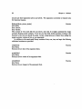
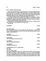
For example, here is a piece of code, that illustrates the usage:
int
parallel.port-startup(boardnumber)
int boardnumber;
int id;
if((fd = open(" :mpp''", board-number, 2)) < 0){
printf(''Couldn't open device?\r\n');
exit(0);
}
/* Reset the board */
mpp.reset(fd);
/* Configure the board to be in raw 16-bit mode */
mpp.c onfig_16bit.raw(fd);
/* return the id, so that the user can use it later */
return(fd);
A/D and D/A converter routines
The following functions are provided for the converters that are supported in the system
in addition to the standard i/o routines like open().
adc.set.gain(fd, gain)
Function
int fd;
int gain;
This routine takes an integer gain value and sets up the board, previously opened, to operate
with that gain. This routine works only on those controllers that have a programmable
gain option.
adcread.channel(fd,channelnumber)
int fd;
int channelnumber;
Function
Chapter4
Software
This routines converts, reads and returns an int from an analog to digital converter's channel
given by channelnumber.
adc.convert(fd, start, count, buj
Function
int fd;
int start;
int count;
unsigned short *buf;
This routine takes the starting channel number start, a channel count count and a pointer
to a buffer buf. It converts the analog to digital channels starting from channel number
start to start + count and stores the resulting values in successive locations pointed to by
buf.
adc.fill.convert(fd, channelno, count, but
Function
int fd;
int channelno;
int count;
unsigned short *buf;
Sometimes it is necessary to convert a single channel repeatedly. This routine provides
the capability for converting a single channel repeatedly, and storing the consecutively
converted values in successive locations pointed to by buf. The channel number is given by
the second argument channelno and the number of times the conversion process is to be
repeated is given by the third argument count.
adc repeat-convert(fd, channelno, count, but
int fd;
int channelno;
Function
int count;
unsigned short *buf;
This routine takes a channel number, a repeat count and a pointer to a short. It converts
the channel repeatedly count times and stores the converted value in the short pointed to
by the last argument.
adc.poll convert(fd, start, count, but)
Function
int fd;
int start;
int count;
unsigned short *buf; This routine is identical in functionality to adc.convert, but uses
polling instead of vectored interrupts to perform its task.
adcpollread_channel(fd,channel)
int fd;
int channel;
Function
§4.3 Level Zero software for the CONDOR
31
This converts a single channel given by channel using polling, and returns the resulting
short.
dac.write(fd, start, no, buJ
Function
int fd;
int start;
int no;
short *buf;
This routine writes to the digital to analog converters starting from channel start, upto
channel start + no, the values found from successive shorts pointed to by buf.
Chapter 4
4.3.7
Software
Simple Real Time Tasking
The CONDOR is a system that was explicitly designed for real time control. The MOS
(or the Minimal Operating System) enables the user to have many real-time tasks running
concurrently. Sometimes, however, it is desirable to have only a single real time task running
on a processor. This is often the case, when data has to be collected during a movement of
a robot or when no useful partitioning of the control loop into many concurrent loops can
be made. For these situations, a simple set of routines that avoid the overhead of the MOS
is provided (this overhead has been measured to be approximately sixty microseconds per
servo invocation). For details on the more complex interface see Section 4.5.1 on Page 77.
The following set of functions are available both on the CONDOR slave microprocessors
as well as the sun. (On the sun, real time interrupts are not guaranteed to be real time,
since the routines mentioned below use the standard Unix interval timer routines).
startservo(loop,rate)
Function
int (*loop)();
int rate;
This function takes a pointer to a function loop and an integer value rate as arguments and
sets up the timer to invoke the function loop with a frequency of rate cycles per second. No
interrupts will actually occur until the servo is explicitly enabled.
enable-servo()
Function
This function enables a servo, if one had been set up using the previous function. This
will cause timer interrupts to occur at the rate desired and the function that the user has
designated to be the servo loop function, will be executed at that rate.
disable.servo()
This function disables a running servo.
Function
servo-status()
This function prints out information about a servo.
Function
servo.ramp(start)
Function
int rate;
This routine is available to the user if the servo. c library is compiled with the BENCHMARK
option. The function provides a very simplistic way in which the user can determine how fast
a servo loop can be run. This function can be made use of only after a call to start.servo
has been made. The function starts from a specified rate and ramps up the servo rate in
steps of ten hertz upto the maximum possible. At each servo rate, it executes the specified
servo loop for some time (approximately 6 seconds). It continues to do this until the servo
loop overruns because an extremely fast rate has been set. The function then reports this
rate as the maximum attainable, for that particular servo routine.
It is an error to call enable_servo if a servo loop has not been set up yet, or when a
servo loop has already been enabled. Likewise, disable_servo must be invoked only when
§4.3 Level Zero software for the CONDOR
a servo has been previously enabled.
stop.servo()
Function
This function stops a running servo as well. However, this has the side-effect of undoing
the effects of startservo. If you want to start up the servo again after this function has
been invoked, you have to set things up using startservo again.
set..servorate(rate)
Function
int rate;
This function sets the rate for the servo designated by startservo to be its integer
argument rate. The function has the side-effect of disabling a running servo. So, in order
to start the servo running again, one needs to call enable.servo again.
Two functions are provided to enable the user to write programs that may require
modification of complex data structures while the servo is executing. (These functions are
also available on the sun, where the processor level returned is really meaningless. The
functions on the sun merely serve to block out the real-time timer interrupts and re-enable
them).
protect..servo()
Function
Returns a short integer on the Ironics end which indicates the current processor level. All
interrupts are masked out after this function has executed.
unprotect.servo(leve)
Function
short level;
Sets the processor priority level to the specified argument level. The above two routines
can be used together as illustrated by the following piece of code:
short level;
level = protect.servo();
<uninterruptible code ...
>
unprotec tservo(level);
If the servo cannot execute at the rate desired, there are two ways the error can be
handled. The first, which is the default, is that the an overrun counter is incremented.
Once the overrun counter exceeds a specific threshold the servo is disabled and a diagnostic
error message is reported at the console. The status routine prints the value of the overrun
counter and can be used to determine if the servo is repeatedly overrunning itself.
Chapter4
4.3.8
Software
HVE Libarary - The memory mapped connection
The HVE library functions are available to enable a user process running on the sun
to use the VME-to-VME adaptor in a flexible fashion. The library functions have been
designed to operate with two kinds of bus-to-bus adaptors in use at the lab. The first is the
SYNERGIST-III/IV kind of system which was an older and 16-bit version of the HVE-2000
which supports full 32 bit transfers across the adaptor.
hveinit()
Function
This function must be called before any other function in this library. It ensures that the
data space (A24D16 in the case of the synergist-3 and A24D32 in case of the hve-2000)
and short i/o space (A16D16) are both mapped into the user space. While the synergist-3
needs to be enabled for operation by a memory write to a specific memory location, the
hve-2000 is always connected. The initialization routine tries to determine which kind of
board it is dealing with and enables it for operation if the board requires it.
hveJnitialisze-data()
This function is called internally by hve.init, to initialize the data space.
Function
hveinitializelo()
Function
This function is called internally by hveinit to initialize the io space.
After the initialization has been done, the programmer can use the following routines
to get a pointer into the address space that has been mapped into his process.
hveget.datapointer()
Fnction
This routine returns a pointer to the beginning of the data space mapped into the user
process that executed the hveinit call. For example, this routine can be used as follows
to read the memory on an Ironics board whose dual-port address has been set to start at
Oxb00000.
read-ram(start, end)
int start, end;
register int i;
unsigned char *beginning.otfslave.ram;
unsigned char value;
int slave.ram-offset - Oxb00000;
beginning.ofslave.ram = hveget.datapointer() + slaveram.offset;
/* Now read the ram starting at start */
for(i-start;i < end; i++)
{
value = *(unsigned char *)(beginningof.slave.ram + i);
printf("Ram address: %lx, Value x\n''",
§4.3 Level Zero software for the CONDOR
beginning.of'slaveram + i,
value);
}
Notice that this enables one to read and write the memory across the adaptor just as if it
were a huge array mapped into the user process.
hve-get-iopointer()
Function
This returns a pointer to the io space on the VME-Bus that is mapped into a running user
process. This will enable one to control devices (normally a-d, d-a and other io devices)
whose device registers are normally located in A16D16 space, directly from a user process
on the Sun.
Function
hve_enable()
This routine, called internally by hve.init enables the VME-to-VME connection. It can
be used by users who wish to be dynamically making and breaking the connection. This
routine works only on the synergist-3. On the hve-2000 it does not do anything.
hve-disable()
Function
This routine disables the VME-to-VME connection. After this routine has been executed,
hve-get.datapointer and hve.get-iopointer will not work until the connection is enabled once again with an explicit call to hve.enable. This routine also works only on the
synergist-3 adaptor and not on the hve-2000.
Chapter 4 Software
4.3.9
Dealing with multiple processors
This section documents routines that are available to the user to provide a more convenient interface to interact across the bus to bus adaptor. Some of these routines are also
available on the Ironics end. These routines are mainly intended as utility functions.
The following routines are available both on the Ironics and on the Sun.
proc.presentp(processor)
Function
int processor;
Takes a processor number as an argument. Returns one if the processor is present in the
system.
proc runningp(processor)
Function
int processor;
Takes a processornumber as an argument and returns one if the processor is running a user
program. Returns zero if either the processor is halted or is running the boot rom monitor.
proc.any-runningp()
Function
Returns one if any processor in the system is running a user program. Returns zero otherwise.
proc-print.status()
Function
Prints the status of the various processors present in the system.
The following routine is provided for one program to control the execution of programs
on other microprocessors:
imonago(processor,address)
Function
int processor, address;
This starts execution of a program on processor at address. The routine is available both
on the Ironics and on the suns. Once a program is running on a particular processor, it
cannot restart itself.
The following functions are available on the sun, to deal with downloading large blocks of
data, and to download executable code to the control microprocessors. These are intended
mainly for programs on the suns. The file server can be used for sending data up from the
ironics and provides a far more flexible buffered interface for doing i/o than these functions:
Function
downloadale(ile(ilename,processor, offset)
char *filename;
int processor;
int offset;
This function downloads an executable found in file filename, onto processor given by the
second argument processor at the offset given by offset. Since the function uses the entry
point commonly defined in object files usually the third argument of fset can be defaulted
§4.3 Level Zero software for the CONDOR
to zero, without any trouble. The function takes care to see that the file will be downloaded
to the correct processor (using the correct dual-port address for that processor).
Function
download.doclear(processor,start, no)
int processor;
int start;
int no;
This function is provided so that a large area of memory on the slave microprocessors can
be cleared (set to zero) extremely quickly from the sun. The area that is zeroed out, will
be on processor specified by processor, and will start at the local address specified by the
second argument start and extend upto start + no;
For transfers down to the slave microprocessors the following function can be used:
download..ablock(buf, processor, addr, count)
Function
unsigned char *buf;
int processor;
int addr;
int count;
This function downloads into the specified address, count bytes of the data block beginning at the address specified by buf. The third argument addr specifies where the data is
downloaded to, and specifies the local ram address relative to the processor specified by
the second argument processor.
For data transfers in the other direction, the following function can be used on the
sun:
uploadinto..file(fdename, proc, start, bytecount)
char *filename;
Function
int proc;
int start;
int bytecount;
This function causes a file named filename to be created which will contain the data starting
from the address specified by start and will contain bytecount bytes. The second argument
proc specifies the processor number from whose local memory the data will be copied.
upload(buf, proc, start, bytecount)
char *buf;
Function
int proc;
int start;
int bytecount;
This function performs much the same job as the previous one, only it puts the data it gets
into a buffer buf which is passed in as the first argument, instead of into a file.
Chapter4
4.3.10
Software
Command Parser Library - Input routines
User level programs often consists of a simple command loop, involving the following
actions:
1. Querying the user, regarding what command needs to be executed.
2. Providing help and documentation when the user requests them.
3. Parsing arguments to the required commands.
4. Executing the commands as requested by the user.
Most control programs may wish to provide such a simple query-processing loop as well.
The following functions are designed to provide the user with a flexible interface for doing
this. The command parser library is NOT part of the standard C library; It is a part of
a utility library that needs to be linked in (with -lutils on the Sun and with -lutils68
for the Ironics) separately as part of the linking process. The command parser library is
based on an underlying emacs-like line editor that is operational at all times. This means
that the user can, at any point in time, use characters like control-A, control-B etc., to edit
his input. The library also provides partial completions, and help to a novice user, which
will be described below.
It must be mentioned that the command loop processing can happen while a servo is
executing in the background. One can use this feature to tune parameters like gains, and
damping co-efficients of a running system. It is this feature that enables the tuning of
control parameters on line to achieve better performance.
execcommand(parameterJist)
Function
This is the most often used entry point into the command parser library. This routine
provides the most often used functionality desired by most command processing functions.
However it does not provide for argument parsing (see below for another function that does
this as well).
The parameterlistis assumed to have the following syntax; Any number of parameters
can be given for a given command processing loop.
The parameter list must be terminated by a NULL.
exec._command('"Command: '',
'"test-I",test_function, "Execute test 1",
S'set-gain'", set.gains, "'Set the gain'",
" set-damp'', set.damping. " Set the damping'',
NULL);
The first argument specifies the prompt for a command loop. The prompt is followed by one
or more comand specifiers, each of which starts with a string representation of a command,
followed by a function that will be executed when that command is typed at the terminal.
This function is assumed to be a simple one, that does not take any arguments. The third
part of a comand specifier list is a string that will be typed out at the user if he types a '?'.
§4.3 Level Zero software for the CONDOR
The routine defines three commands as built in, and these must not be defined by the
user. The first is a command called "'help' ', which can be executed by the user just as
any other command. What this function does is it types out the command names followed
by their documentation strings given as part of their command specifiers. The second is
the command ''quit'' which quits the exec.command routine. This enables one to build
different levels of command loop processing. (for example, the set.gains routine could itself
have an exec.command specification - when this routine is executed the new command loop
will be the one that takes effect. When the user quits out of this loop, he will be returned
to the old command loop).
There is nothing unusual about the command loop processing itself. What makes it
unique and useful is its interactive nature. If the user types set- and then a special
completion character (which is presently set to tab, the system will automatically search
the current command table and respond with:
Partial completions:
set-gain - Set the gain
set-damp - Set the damping
If only a single match was found, the routine will complete the partially typed input automatically.
Typing '?' at any time (or any other assigned help character) will cause the help routine
to be executed. Typing carriage return or newline at any time is equivalent to signalling
that the user is done with his input. The routine tries completing his partially typed in
input - if a valid match is found, the full completion is printed out before the command is
executed.
While typing input, a subset of emacs-like editing commands can be used to alter the
input buffer.
get.keyword(prompt, keywordJist)
char *prompt;
Function
The exec.command routine is built on top of a facility that can be used in a very general
manner. Another routine that uses the basic facility is a facility to read keywords from the
terminal while providing input editing, completions, and partial matches. The get-keyvord
routine takes a keyword list which is basically a sequence of character string arguments
terminated by a NULL argument. It prompts the user with a prompt argument and returns
the string keyword typed at the terminal, or minus one if the user aborts with an abort
character, which is presently set to control-g.
get keyword.value(prompt, keyword.valueJist)
char *prompt;
Function
This routine is very much like the routine above. The difference is, that here instead of
specifying a string of keyword values all of which are strings, the user specifies keywordvalue pairs. The routine returns the value associated with a particular keyword when that
keyword is typed at the terminal.
For example:
Chapter4
Software
int base - get.keywordvalue('"Type in a base: "
"decimal", 1,
'hex", 2,
'octal", 3,
NULL);
This will set the variable base to be equal to 1 if the string ' 'decimal' ' (or a recognizable
partial string that complets to it) is typed at the terminal.
The returned value can be anything that can fit into a valid integer object.
execute.command(prompt, commandliat)
Function
char *prompt;
The most generic form of command parsing function is provided by this function. Like
exec.command it provides the basic facility to parse and execute commands. In addition,
it provides programs with the ability to parse for arguments from a predetermined set of
types. This routine is very much in the experimental stages. Full documentation on how
to use this facility will be forthcoming shortly.
4.3.10.1
Miscellaneous input routines
Besides the above routines, the following routines provide the user with the capability
of getting input from the user. They can be used anywhere in a user program intermixed
with command parser library calls.
* Strings and characters:
Function
tty.gets(buffer, prompt, redisplayflag, complete)
char *buffer;
char *prompt;
int redisplayflag;
char *complete;
This routine displays the prompt and gets a string from the user, with input-editing a-la
emacs. Returns when the user types one of the completion-characters given in the string
complete. If redisplayflag is zero nothing is done. If it is one, then the buffer passed in
as argument is put into the edit buffer first, displaying it for the user to edit. If the flag
is equal to two, then the buffer passed in as argument is put into the edit buffer but no
display is done, of this string.
The following routines are part of the same utility library to read integer values from
the terminal, using a flexible syntax which is explained below.
Function
tty-readimmediate()
This routine returns the next character typed at the terminal by the user. Returns negative
one if the user types an abort character (presently set to control-g.
* Numbers:
§4.3 Level Zero software for the CONDOR
A number is specified by #<radix-value>r<number>. This syntax is borrowed from LispMachine usage. The following synonyms are predefined.
#16r
#8r
#2r
#10r
can
can
can
can
be
be
be
be
written
written
written
written
as
as
as
as
#x.
#o.
#b.
#d.
If radix is not explicitly specified with a #, it defaults to 10, or the last set radix.
For example:
#xa
#blO1
#o10
#8r10
-
stands for number 10 decimal.
stands for 5 decimal.
stands for 8 decimal.
#o10
Any valid radix from 2 to 36 can be specified. The function complains if you type a
character that it is not able to recognize in the current radix. (for example: 'f' is not a
valid character in base 15).
If one specifies 's' instead of the 'r' then all future reads will use the specified base for
input. The default base on startup is 10. So, to set the default base for reading in numbers
to be hex, one can type
#16sal000 or #xsa1000
when prompted for the first time.
read-int(prompt)
char *prompt;
Function
read validint (prompt)
Function
char *prompt;
Both the above routines prompt the user with the given argument prompt and attempt
to parse for an integer. The latter routine will handle user errors, and will continue to
reprompt the user until a valid integer is typed.
read.Jnt-n.range(prompt,begin, end)
Function
char *prompt;
int begin;
int end;
Reads and returns an integer greater than or equal to begin and less than or equal to end.
Chapter4
4.3.11
Software
Window system functions
Most system programs written to control the hand, rely on using the X-Window system
and the Sx-Library for the Toolkit functions provided on top of the X-Window system.
We document here, our extensions to the X library which we have found useful, and other
programmers may wish to use. It must be said that this version is based on Version 10 of
the X window system, and parts of the library may change with Version 11.
The library is written so that it will provide a simple, easy to understand, interface
for programmers who wish to deal with the window system. In most cases, it chooses a
reasonable set of defaults which helps to standardize the interface across most programs,
and frees the programmer from worrying about them.
All functions in our extension library begin with the characters xwv The library predefines certain fonts for the convenience for the user as well.
The fonts are:
xw_textfont
Variable
xw textfont.name
Variable
This is the default font for text. The variable with .name appended to it describes the
character string representation of the name of the font, while the former refers to a data
structure of type FontInfo *.
xw.bigfont
This refers to a larger text font.
Variable
xwitalicfont
This is the default font used for italic text.
Variable
xw_boldfont
This is the default bold faced font.
Variable
xw.smallfont
The default small text font.
Variable
xw.startup(host, name, z, y, width, height)
char *host;
char *name;
Function
int *x, *y, *width, *height;
This function initializes the X library, the Sx library and Xw libraries. The first argument
host refers to the display on which the program is to be run on. The second argument
name refers to the program name as it should appear on the title bar window. This routine
provides an initialization interface such that the size of the initial program window created
are returned in the next four arguments. If a default value for these values is not provided
§4.3 Level Zero software for the CONDOR
the program will attempt to get the user to use the mouse to locate the left top and right
bottom corners of the window in which the program should run.
An alternate startup interface is provided by the following function.
xw.create.root(z, y, width, height, host, name)
Function
int z,y,width, height;
char *name;
char *host;
The name, and the host arguments have the same meaning as in the function above. The
first four arguments specify where the root window of the program is to be created.
xw..getpoint-from..mouse(window, z, y)
Window window;
Function
int *x, *y;
This routine uses a cross cursor to obtain a position from the user. It grabs the mouse until
it is clicked and returns the location where it was clicked in the variables z and y.
xw...tracking.mouse(window, function)
Function
Window window;
int (*function)();
This routine grabs the mouse in the window specified by window. As the mouse is moved
in the window, it calls the function specified by function repeatedly with two arguments z
and y which are set to be the current co-ordinates of the mouse within the window. The
tracking is stopped when the user clicks any of the mouse buttons.
xw.get.rect-from.mouse(z, y, width, height)
Function
int *z, *y, *width, *height;
This function grabs the mouse and reads two points from it, which are set to be the left-top
and right-bottom of a rectangle on the screen. The function returns the rectangle in the
variables pointers to which are passed to it as arguments.
xw.get window-from.mouse()
Function
This function grabs the mouse and returns the Window in which the mouse is subsequently
clicked. This can be used in choosing a window.
xw.istener.create(window, label, width, height, font, zorigin, yorigin)
Function
Window window;
char *label, *font;
This function creates and returns a pointer to a window that has an xterm process associated
with it. Such a window provides the terminal emulator functions that are required by
programs doing text output. Such a listener window, once created can have a command
parser loop running inside it. The precise manner in which this can be done, is explained
below.
Chapter 4
4.3.11.1
Software
The command parser and X Windows
The command parser that runs on the Ironics slave microprocessors and the Sun also
runs under the Xwindow system. The following section will describe very briefly how to
use the command parser from within user programs to get a relatively powerful interface
running on the X window sytem.
As mentioned earlier, the command parser provides a flexible way of specifying a top user
level command loop interface. Under X things are a lot more complicated since X responds
with events when the user types at his keyboard or moves the mouse, and programs that
expect input from stdin have to be modified to understand this. When one creates an X
window moreover, one does not get a powerful object, but a rather primitive one. Although
toolkits are supposed to provide the added functionality of utilities like scroll bars, they
are not available at this time.
The xw functions provide a programmer with a way of creating a powerful interface
with very little work. The following example will illustrate how the user can create a
window under the X window system and associate a command parser with it.
The first function that must be called as mentioned before, is:
Window root;
root=xw.startup(displayname, programname, &x. y, &width, &height);
This function will startup the xw library on the display provided by display, and give
it a title programname. The next four arguments to it are pointers to integer variables.
The initialization code looks in the user's .Xdefaults file for these variables. If they have
been specified there, the program is initialized with those desired choices (the four variables
specify the x-origin, the y-origin, the width and height of the program's window respectively). If the user has not specified them in his defaults file, the routine prompts him for
the values with the mouse for the left top and bottom right corners of the program window.
After the root window has been set up, a number of listener windows can be setup to
run under it, as follows:
TTYWindow *windowi;
windowl = xw.listener.create(root, "Commandi". 40, 20,
"9x15", x, y);
This creates a listener window in which a command loop will be run. The listener
window is really an xterm window, that the user program communicates over a pty ', but
this is totally hidden from the user, as we will see below. The first argument is the window
as whose subwindow the listener window will be created. The second argument forms the
label for the window, which is presently ignored. The third and fourth argument specify
the width and height (in terms of characters of the specified font) of the window. The fifth
specifies the font to be used, while the last two arguments specify the left top corner of the
listener window relative to the parent window in which it will be created.
After a listener window has been created, a command loop is usually associated with
the following routine:
'pty is the Unix abbreviation for pseudo terminals
§4.3 Level Zero software for the CONDOR
Xexec-command(windowl, "Command: ",
"foo",
too,
"A foo Command",
"bar", bar, "A bar command",
"baz", baz, "A baz command",
0);
The first argument is a pointer to a TTYWindow created by a call to xwlistener.create.
The second argument is the prompt, that must be used each time during the command
loop. We recommend that a non-null prompt be used always, since things can get confusing
if you do not know where your input buffer begins in an X window. Notice that this function takes arguments in a manner that is similar to the exec.command routine - the only
difference is in the first argument, which is a pointer to a TTYWindow created by a call
to xw.listener.create. The other difference is that while the former never returns until
the user executes the builtin command quit from the command loop, the Xexec.command
routine returns immediately.
After a number of such listeners have been created, the user then calls
xw.handle-events (handlerroutine);
What this routine does is it provides support for the command loop processing. Whenever there is X activity that this routine does not understand, it calls the user specified
handlerroutine which must be a function that expects no arguments.
This function does not interpret other X events that happen in any fashion, nor does it
modify the X event queue. Thus one can use this routine in conjunction with other Toolkit
libraries; For example if handlerroutine was declared to be
handlerroutine ()
while(XPending()) {
XEvent event;
INextEvent (kevent);
SxHandleEvent(kevent);
one gets a set of listener windows that works with the Sx library.
All this is very straightforward. Now let us briefly mention a few features of the system
not found in conventional toolkits.
1. The command loop dispatching provides for completion. In the above example, if the
user types i and then hits any of the completion keys (these are presently set to TAB
and ? ) the function will look up the command table and complete the rest of his
input to
Command: f<tab>
Command: ioo
(in the same line)
Chapter 4 Software
2. The command loop editor provides a line editor a-la emacs. Characters like controla, control-e, control-f, control-b, delete, control-e etc., work with their emacs like
behaviour in the input buffer.
3. Partial matches are also recognized. In the above example if the user types a completion character after typing the character b the system will respond with
Command: b<tab>
Partial Completions:
bar - A bar command
baz - A baz command
4. A few commands are built in. These are help, alias and quit. The first provides
help if the user types ? or help. The second allows aliasing one command to another,
and the third enables one to quit one command processing loop. (This is needed
because the user can call the Xexec.command from within one of his functions. This
makes the command loop processing stack oriented. At any time one command loop
is active in each TTYWindow. When you quit out of it, it is popped of its stack and
a previous command loop is made the current one. For example if you had written
inside of foo()
Xexec.command(window, "Command-level-1: ",
"apples", apple, "Eat an apple",
"oranges", orange, "Guess what",
0);
After foo finishes executing, you will be prompted, not with
"Command: "
as before, but with
"Command-level-1:
"
and the new command table will be in effect.
5. Commands are invoked with two arguments, and while they execute, stdout will be
bound to the window in which the command loop will be running. (Using printf
from inside a command function will therefore work, and the output will appear in
the designated window). The first argument passed to the executing function will be
a pointer to a string starting from after a recognizable command in the input buffer.
The second argument will be the TTYWindow in which the command was executed
from. For example, if you had written foo() to be
§4.3 Level Zero software for the CONDOR
foo(buffer, window)
char *buffer;
TTYWindow *window;
printf("Rest of the string %s\n", buffer);
}
You will be able to type "foo is foo" at the command prompt and get the response "Rest of the string is foo". Notice that completion and partial matches
all work on the first word alone. It is upto the user program to interpret the rest of
the buffer as it pleases. This provides a simple mechanism for providing arguments
to the functions in the command table, which is described later.
Note:
Command functions must be written in a fashion so as to be quick and do no reading from
stdin. If they do, these functions could hang awaiting input, and all window system activity
would freeze.
End Note.
4.3.11.2
Parsing for arguments in the command parser
Often routines that one wishes to write, expect arguments. These arguments in some
cases are merely strings, or numbers. In other cases they are complex like pathnames
or filename components. To parse for all combinations of these arguments is certainly a
complex task. What the command parser library provides is a simple way for doing this.
The main routine that parses for arguments is the Xparse.argument routine. This
function can be invoked both inside the X version of the command parser and the non-X
version of the command parser.
The user can invoke this function as illustrated in the following example:
foo(arg, window)
char *arg;
TTYWindow *window;
char buf [80];
if(Xparseargument(karg, STRING, buf, "Type in a string",
"error in parsing string arg?") < 0)
return -1;
printf("Got argument: %s\n", buf);
The first argument MUST be always the address of the rest of the input string, that
the user defined routine is invoked with. The second argument is a type indicator. A
number of predefined types and routines that parse for them have been already written,
and there isa flexible way that the user can define his own types too, as will be described
Chapter 4
Software
later. The third argument is usually a pointer to a variable which will hold the parsed
argument. In the case of a string variable or a filename argument this will point to a char
buffer, but in the case of an integer this will be a pointer to that integer variable. The
third argument is a help string that will be typed at the user if he does not specify that
argument. In the above example, if the routine foo was invoked by the user typing "foo" at
the command parser, the Xparse.argument routine will try parsing for a string argument
that comes immediately after the command (separated by a space or a tab). If it finds no
such argument it will type the help string at the user and return to the top level with his
input still in the visible input buffer for him to edit or add to. The following will illustrate
what happens in the above example
Command: foo<RET>
Type in a string
Command: foob<RET> No matches.
Command: foo b<RET>
Got argument: b
Command: foo bar<RET>
Got argument: bar
The predefined types are: STRING, FILENAME, INTEGER, CHAR, FLOAT. There is a
mechanism for the user to define his own types in addition to those mentioned above. An
example of how this is done will illustrate the generality of the mechanism:
First, the user ought to choose a type code dispatcher (usually this is a small integer
greater than 20);
#define KEYWORD
20
Then a parsing function is associated with the type code as illustrated below:
char *mykeyword();
definetype(KEYWORD, mykeyword);
All user defined types are defined as shown above, by specifying a type code followed
by a routine that is to parse for arguments with that type. All type parsing routines must
be written so as to return a pointer to a string value. They must all take 3 arguments as
shown below:
char *
mykeyword(bu,f
int *retval;
char *buf;
int *valid;
valid, retval)
*valid - -1;
if (buf == NULL) return(buf);
if (*buf == NULL) return(buf);
§4.3 Level Zero software for the CONDOR
if(strncmp(buf, "yes",3) - 0) {
*valid - 1;
*retval = 1;
return((char *)(buf+3));
}
if(strncmp(buf, "no",2) -== ) {
*valid = 1;
*retval = 0;
return((char *) (buf+2));
}
return(buf);
That is all one need to do, in order to define a user-defined type. Once the parsing
function has been associated with the type code, one can use the Xparse.argument routine
as illustrated below, in any one of the command functions.
if(Xparseargument(karg, KEYWORD, kval, "boolean test value".
"only yes or no please?") < 0) return -1;
The type parsing routine will be invoked with the REST of the input buffer as the first
argument. What this means is that if you define a function called foo and invoke it by
typing foo bar baz, the first argument to the first argument parser routine will be the
string bar baz. This routine can therefore look at however much of the input it wants to
look at - but it must return a pointer to the REST of the buffer after it has done so. So, in
the above example, if the first argument was supposed to be a string delimited by spaces,
the first routine will parse upto the space following the bar, and therefore return a pointer
to the string baz. This means that the contract of each argument parsing function is fairly
simple - It is always invoked with the rest of the input buffer. It can look at however much
of the input buffer as it wants to, but it must always return the rest of the input buffer so
that routines that parse for arguments coming after this one will be invoked correctly.
The command parser routine's second argument will be a pointer to an integer. This
variable must be set to -1 at the beginning of your parsing routine, and set to a non-negative
value to indicate a successful parse. This enables the Xparse.argument routine to recognize
if a user defined argument parsing function has detected an error. The third argument to
the command parser routine is a pointer to a pointer to an int. The user defined routine
can set this variable to anything that it parses for - this is how it communicates the value
that it parsed back to Xparse.argument routine. In the above example, the user defined
keyword parser, sets the retval variable to be 0 or 1 depending on whethere the user typed
a yes or a no.
An example of a program that uses the command parser, X windows and the xw functions extensively is the default user interface program condor. Users who expect to be
writing a lot of user interface code, are advised to look at this program's source for examples of all the functions that we have described above; The compactness of this program is
a prime example of the usefulness of the user interface library.
Chapter 4
4.3.11.3
Software
Window Geometry
There are functions that provide an interface for managing the geometry of window
layouts as well, in addition to those provided by X and Sx.
Included in the utilities is a package for window configuration. This package permits
the creation and management of subwindows. The basic concept is that a window may be
split into many subwindows along either the horizontal or the vertical. The size of each
subwindow can be specified as a percentage of the total window. These subwindows can in
turn be split into subwindows of their own.
The geometry management package is divided up into two main layers; the lower level
structure management and a higher layer of user structures and routines. The higher level
will be described first since that is the level that programmers should use. This level
depends on the lower level and the one structure that needs to be described before hand is
the wr structure:
struct wr {
Window wrid;
RECTANGLE wr.rect;
/* window */
/* rectangle it is associated with */
/* RECTANGE consists of x,y,width and
height */
The user layer of structures and routines is meant to simplify the construction and maintenance of complex displays. It is based on a tree structure with each node being a division
of the previous node. The top of the tree represents the window and the leaves of the tree
represent the subwindows. The user first creates a tree, then splits each layer as they desire.
The tree stores only the percentages of the splits and no calculation of actual coordinates
is done until the user specifies. Sub-trees may be resized, or even hidden (by setting the
sizes to 0). Once the tree has been set up appropriately, the user can make windows or
terminals from the tree. This creates windows for only the leaves of the tree. If the root
window of the tree is later resized, the user only needs to change the size of the root node,
call for recalculation, and ask to change the size of the windows from the tree. To facilitate
easy access to the leaves of a tree, they can be counted and collected into an array.
The main tree structure is as follows:
typedef struct WINDOW.TREE {
int number.ofchildren;
int direction;
struct wr *wrec;
int *percentages;
struct WINDOWTREE *children[MAXCHILDREN] ;
TTYWindow *proc.tty;
} window-tree;
The routines are:
§4.3 Level Zero software for the CONDOR
geom.tree.new.node(z, y, width, height)
Function
int z,y,width,height;
Creates a new tree whose root has the specified coordinates. This should be the first routine
used to create a tree. The routine returns a pointer to a struct window.tree when it is
done.
geom..tree.split (parent, direction, number.of-children, list)
Function
windowtree *parent;
int direction; /* ROWWISE or COLUMNWISE */
int number..ofchildren;
vararg list;
This will split a node of a tree into the specified number of subnodes. Each of these subnodes
can be accessed as a tree itself. The list is a list of percentages to be used for the size of
each child. If the first element in the list is -1, then all the children are equal, otherwise
there should be a value for each child. This can be called on any node of the tree. An
example of the several calls to split follows:
mytree = (window-tree *)new.node(x,y.,width,height);
split(my.tree, ROWWISE, 2. -1)
split(my-tree->children[0],COLUMNWISE, 2, 30, 70);
split(my-tree->children[1] ,COLUMNWISE. 2. 70, 30);
This will create a structure that would look as follows:
********************
********************
geom.tree.resize-parent (parent,z,y,width,height)
Function
windowtJree *parent;
int zy, width, height;
Change the size of a parent in the tree. This will cause all the subtrees to change size when
they are recalculated. It should only be called on the root of the tree. Since the sizes for
all the subtrees are calculated in recalculate.
geom-tree.recalculate(parent)
Function
windowtree *parent;
Recursively recalculate the actual sizes (in pixels) of every node in a tree. It uses the x,y,
width and height of the root node, and the percentages of all the subnodes to set the x,y,
width and height of every node in the tree. This routine must be called before all operations
that attempt to display the tree, and should usually be called only on the root of a tree.
Chapter 4
Software
geom.tree.change.direction(parent,
direction)
Function
windowJtree *parent;
int direction;
Change the direction that children are split from in any node of a tree. The direction may
be either ROWWISE or COLUMNWISE. This can be called on any node of the tree.
geom.tree-resize.children(parent,number.ofchildren, list)
Function
windowJree *parent;
int numberofchildren;
vararg list;
This will resize the children of any node in the tree only up to the number of children that
originally exist for that node. List is a list of percentages that can be used for the size of
each child. If the first element of the list is -1, then every child of the node is given the
same size. It is acceptable for a child to have 0 percent size, in this case that child (and all
its subchildren will still exist but have no size and hence not be displayed).
geom.tree.make.windows.from.tree(parent, root-window)
Function
windowtree *parent;
Window root-window;
This routine will use the tree given (it should be the root of a tree) to create subwindows
in the given window. It will recursively step down the tree and create a subwindow only
for each leaf of the tree.
geom_tree.make.terminals.from.tree(parent, root-window)
Function
window-tree *parent;
Window rootwindow;
This routine will use the tree given (it should be the root of a tree) to create subwindows
with terminals in each subwindow in the given window. It will recursively step down the
tree and create a subwindow only for each leaf of the tree.
geom.tree.change.windows.from.tree(parent, root.window)
Function
window-tree *parent;
Window root-window;
This routine will resize the windows in rootLwindow using the given tree. Care must be
taken that this window corresponds to the given tree or errors will occur since the program
will attempt to resize windows that may not exist. If a node is encountered that has a width
or height of 0 then that subwindow is unmapped. If a node that used to be unmapped
(because its width or height was previously 0) and now has a width or height, then it is
mapped. If the user resized the root window, all one needs to do to keep the subwindows
at their appropriate size is shown in the following example:
XqueryWindow(ROOT, kwinfo); /* get the new size */
/* resize the parent */
resizeparent(my-tree,winfo.x, winfo.y, winfo.width, winfo.height);
§4.3 Level Zero software for the CONDOR
/* recalculate the tree */
recalculate(my-tree);
changewindowsefrom.tree(mytree, ROOT); /* change the
subvindows */
geom-tree.countleaves(parent)
Function
windowJree *parent;
Returns the number of leaves in a given tree (or number of children that a given node
contains).
geomtree-getleaves(parent,leaf.array)
Function
windowtree *parent;
windowtJree **leaf-array;
Does not allocate storage, but fills leaf.array with the leaves of the specified tree. An
example of the way to get an array that contains the leaves of a tree follows:
num.leaves = count.leaves.in.tree(mytree);
leafarray - (window.tree **)malloc(sizeof(window.tree) * num.leaves);
get.leaves(mytree, leaf.array);
The basic data structure for this layer is the wr which was specified before. It consists
of a rectangle x,y,width,height and a window id.
Routines are provided for:
Setting this structure:
geom.setstruct(wr, zy, width, height)
struct wr *wr;
Function
int z,y,width,height;
geom.setfrom.winfo(wr,info, id)
Function
struct wr *wr;
Winfo *info;
Window id;
Creating this structure:
geometryJnit(id)
Window id;
Function
Takes a window id and returns a pointer to the wr structure that is associated with that
Window.
geometryInit.fromsize(z, y, width,height)
int z,y,width, height;
Function
Chapter4
Software
Does the same thing as the routine above only instead of taking a window Id it does this
from the rectangle parameters provided.
Creating a window using this structure:
geometry.create(wr)
struct wr *wr;
Function
Mapping an associated window:
geometry.map(wr)
Function
struct wr *wr;
And most importantly splitting the structure:
geometry.split(wr, direction, number, percent~ist)
Function
struct wr *wr;
int direction, number;
int percentlistf];
geometrysplitfrom.window(id, direction, number, percentJlit)
Window id;
int direction,number;
varargpercentlist;
Function
This routine is the basis of the entire geometry package and is called from the higher
level split routines. Using the wr structure, it splits the structure and returns the specified
number of subwindows (though the window ids are not filled in at this point) in an array
of wrs. The percent list is used to specify the size of each window that is split or if it is
NULL, each subwindow is sized equally.
For further documentation on the X window system see the document "Xlib - C library
interface to the X Window system", and for documentation on Sx please see the document
"Sx Overview".
§4.3 Level Zero software for the CONDOR
4.3.12
Hash Tables
The utility library also includes a fast hash table library for looking up data associated with keywords. The functions provided by this library are described below. The file
vie/hash. h needs to be included by any file that needs to use these functions.
htinit(size)
Function
size;
This function initializes the hash table modules and returns a pointer to a hash table object,
which is typedef'ed to be hashtable. Therefore, to use this, one would do
hashtable ht;
ht - htinit(HASHTABSIZE);
The size of the hashtable depends on the application.
htinstall(key, table, data)
Function
char *key;
hashtable table;
char *data;
This routines associates the given data item with the specified key, in the given hashtable.
The data item can be a pointer to a user specified data structure if need be. The install
routine returns negative one if it fails for some reason. If the key already exists in the table,
the old association is forgotten.
htlookup(key, table)
Function
char *key;
hashtable table;
This takes a key and looks it up in table. If the entry is not found it returns null. Otherwise,
it returns a pointer to a structure of type htentry which is declared in file hash. h to be:
struct ht.entry {
char *ht.key;
char *htdata;
struct ht.entry *ht-next;
Users normally will not need to use this function, but instead can use the following function,
if they need to retrieve the value associated with a particular key.
htgetdata(key, table)
AFnction
char *key;
hashtable table;
This function takes a key and a hashtable table; it returns the value associated with the
key if found in the given table or null if not.
Chapter4
htmnap(table, function)
hashtable table;
Software
Function
int (*function)O;
This calls the specified function successively with every element in the hash table. The two
arguments passed to the function are a pointer to the data associated with a particular key,
and the key itself.
htstat()
Function
Prints out various statistics concerning the usage of a hashtable if it contains any entries.
htdelete(key, table)
Function
char *key;
hashtable table;
This function deletes the entry associated with the specified key if it is found in the table
specified by table. If the item is not found in the table, it returns negative one.
hthash(s, table)
Function
char *s;
hashtable table;
This routine takes a key value and a hashtable, and returns an offset number into the table
of entries. Since the hash table internally uses linear chaining to handle collisions, using
the offset directly will yield a list of entries all of which hashed to that same value as the
specified argument a.
htclobber(table)
Function
hashtable table;
This function deletes all the elements and deallocates a hash table. Consequently, this
must be used only with great care. If the hash table datum are pointers to dynamically
allocated objects, the user must free the data objects individually before deallocating the
table. Usually this can be done with:
htmap(table, free);
§4.3 Level Zero software for the CONDOR
4.3.13
Buffer routines
The buffer manipulation routines provide a low overhead way of managing data that
needs to behave like a FIFO queue. It is extremely easy to write a set of linked list
manipulation routines that do what the functions documented below do. However, the
routines below, require the user to specify what the size of the buffer pool ought to be in
advance. This provides a way of controlling memory usage, which could get to be expensive
in certain kinds of computation.
To use the routines in this library you must have cbuf .h included in your source file
with a line that says,
#include <cbuf.h>
The functions that are user visible in this module are:
buffer.create(no.elements, size)
int no.elements;
Function
int size;
This function takes in two arguments, and returns a pointer to an element of type struct
circular.buffer. The first argument no.elements is the number of elements that the
queue is designed to hold and the second argument size indicates the size of each element.
For example, to create a buffer to hold ten file structures one can write
struct circular-buffer *cb;
cb - buffer-create(10, sizeof(struct file));
Once the buffer has been created, the user can use the following functions to add and
delete elements from the queue.
buffer-put(queue, object, dontwait)
Function
struct circularbuffer *queue;
char *object;
int dontwait;
The first argument is a pointer to a queue to which the second argument object must be
added. If the third argument dontwait is set to one, then the routine will return immediately
if it does not find any space in the queue to hold the new object, returning minus one to
indicate failure. If the third argument is set to nil, then the routine will wait until space
becomes available in the buffer. Notice that it makes sense to do this only if the queue is
being emptied by some other process. The element is added to the queue by the bcopy()
routine, and is assumed to be of the same size as the elements for which the queue was
created in the first place.
bufferget( queue, dontwait)
struct circular-buffer *queue;
int dontwait;
Function
58
Chapter4 Software
This routine takes a queue as the first argument and returns a pointer to an element popped
off it. Notice that this routine just returns a pointer to an element - If the user needs to use
the returned object later on in his computation, he had better copy it into his own locally
allocated variables. If the second argument dontwait is one, then the routine returns nil
immediately, if the queue is empty. If dontwait is nil however, it waits until an element
appears in the queue.
§4.3 Level Zero software for the CONDOR
4.3.14
Tree library
The command parser and other such system libraries use a set of functions that operate
on binary trees. The functions in this library are documented briefly in the following
section.
tree-create(elementsize, predicate)
Function
int elementeize;
int predicate;
This routine creates and returns a pointer to a struct btree. Each element of the tree is
set to be of size elementaize and predicate is a function that imposes an ordering relation
between the elements of the tree. This function must be written so that it can take two
nodes as arguments and return a value that is less than, equal to or greater than zero
depending on whether the first node is less then, equal to or greater than the second node.
The function should return zero only if the two nodes are identical.
tree.free(root)
Function
struct btree *root;,
This routine frees all elements and the memory associated with a particular tree. All other
calls made to the tree package with a tree that has been previously freed will fail, after this
call.
tree.insert(root, elt)
Function
struct btree *root;
char *elt;
This routine inserts element specified by elt into the binary tree specified by root. The
routine returns a pointer to the modified tree data structure. Note that the size of the
element to be added to the tree must be equal to the size of the elements for which the tree
was created to handle. The insertion of the element will happen at the right place in the
tree as specified by the ordering function.
treelookup(root, elt)
Function
struct btree *root;
char *elt;
This routine will search for elt in the tree specified by root. If a match is found (as indicated
by a returned value of zero by the user supplied comparison predicate function) then that
element will be returned. If no match is found then the routine returns NULL.
tree-delete(root,elt)
Function
struct btree *root;
char *elt;
This function deletes element specified by elt from the tree specified by root. It returns a
pointer to the modified tree.
60
Chapter 4 Software
tree.traverse(root,way, function)
Function
struct btree *root;
int way;
int (*function)(;
This function traverses a specified tree in a manner specified by way, which can be one
of POSTORDER, PREORDER, INORDER. If specified the function is invoked once with every
element as its single argument.
§4.3 Level Zero software for the CONDOR
4.3.15
Small set package
This package comprises of a set of routines to manipulate small sets of integers (typically
between the integers 1 to 32). In the Utah-MIT hand which has sixteen joints, such a
package comes in handy at the level of joint control.
The set is based on bit vectors and can be easily extended to larger set sizes, should
that be required. All the functions given below require one to include the file <set.h>.
set-emptyset()
This creates and returns an object of type SET, that is empty.
Function
set.singleton(i)
Function
int i;
This routine creates and returns an object of type SET that contains a single member,
indicated by i.
set.add.element(set, elt)
Function
SET set;
int elt;
This adds the specified integer elt to the set specified by SET. The routine returns the
modified set.
set..delete.element(set, elt)
SET set;
int elt;
This routine deletes elt from the specified set.
Function
set.memberp(set, elt)
Function
SET set;
int elt;
This function is a predicate that returns one if the given element elt is a member of the
given set and zero if it is not.
set intersect(setl, setd)
SET setl;
SET setl;
This function returns the set intersection of the two specifed sets.
Function
set.union(setl, set2)
SET setl;
SET setl;
This function returns the set union of the two specified sets.
Function
62
Chapter4 Software
set.difference(setl, setd)
Function
SET set1;
SET set1;
This function returns the set difference seti - setM.
In addition to this routine a forall macro is available that can be used as follows:
int joint;
forall(joint, currentlyselected.joints) {
printf ('Joint Ud, Gain Ud, Damping Md\n' '
joint, Joint [joint] ->gain,
Joint [joint] ->dampint);
}
where currently..selected.j oints is a SET that has been appropriately initialized.
§4.3 Level Zero software for the CONDOR
4.3.16
Miscellaneous routines
These routines are included here, since they do not fall into any of the above mentioned
categories.
abortO
Function
This is different from the Unix abort 0()that is defined to produce a coredump of a running
process. Our version merely exits a running program, and returns control to the Boot Prom
monitor.
exit(status)
Function
int status;
Returns from a running C program to the Boot Prom monitor. Exit code status is presently
ignored.
_ccleanup()
Function
Function that waits until all the terminal queues have been flushed before returning. This
is called internally by exit but users may find it useful on occasion too.
Function
.panic(atring)
char *string;
Function that prints out the string at the terminal and then causes the program to terminate. Used to indicate that an abnormal and non-recoverable error occured.
isatty(d)
Function
int fd;
Returns one if argument fd is less than three. This function can be used to find out if a
given file descriptor is attached to a tty.
_.setprocid(id)
AFnction
int id;
Sets the current processor id to be that of the argument id. Use this function with care.
_getprocid()
Function
Returns the processor id of the processor on which the program is currently running.
rand()
Function
srand()
Standard Berkeley Unix semantics.
Function
syserr(no)
Function
Chapter 4
Software
int no;
Prints out the error message corresponding to system error number no. This routine also
sets the global variable errno to be the given error number.
errno
Variable
Global variable that can be examined to find out the cause of certain system error codes.
4.3.17
Internals
In this section we document those few functions that are either internal to the implementation or on the way to becoming obsolete. We provide this information for users who
need to delve into the internal implementation.
4.3.17.1
Interrupts and Vectors
The following functions allow the user to manipulate interrupt vectors on the slave
microprocessors. These routines affect the system at the lowest levels and hence we do not
recommend they be used by the casual user. There are many more functions that make up
the internals than are documented here - we have chosen to document below only those
functions that we felt needed documentation. The normal user is advised to stay with the
higher level interfaces meant for handling terminal i/o, timer interrupts, mailboxes and so
on, so that his code will port easily and be immensely more readable and maintainable.
splx(level)
Function
int level;
This routine turns off interrupt processing at levels below the specified by level. Internally
it calls routines spl0 through sp17 on the Ironics board that has seven interrupt levels
since is is based on the Motorola 68020 processor. Doing a splx(7) is equivalent to doint
a spl7 (), and turns off all interrupts below level 7, which basically turns off all interrupts.
Correspondingly doing a splO() enables all levels of interrupt on the processor.
The vector library provides a mapping between vector numbers and routines that these
vector numbers should invoke. The Motorola 68020 defines a number of system vectors and
leaves a number of vectors unspecified so that a user can assign devices that provide support
for vectored interrupts can use them. (Please see the document on how to write device
drivers for documentation on how to choose a vector number when you are configuring a
new piece of hardware into the system).
The following functions provide a flexible interface to the programmer who needs to
deal with vectors:
Function
vectorinit()
Initializes the vector system. This is done automatically upon system initialization so the
normal user would not need to call this.
vector-print(vectornumber)
Function
§4.3 Level Zero software for the CONDOR
int vectornumber;
This routine prints out a short description of the routine assigned to the vector number
specified by veetornumber.
vector-printall()
Function
This routine prints out the entire mapping in place, that maps vector numbers to routines.
vector.set(num, routine, name)
Function
int num;
int (*routine)O;
char *name;
This function takes a vector number given by num and a routine given by routine and sets
up the mapping so that that function will be invoked when an interrupting device supplies
the designated vector. The third argument name is a string describing the use of the vector
and is purely for descriptive purposes.
The routines designated to be interrupt vectors should all be off the following form;
int
bus-error.handler(num, registers)
int nun;
char *registers;
These functions will be invoked by the system. The first argument passed to them will be
the vector number that caused the invocation, and the second argument will be a pointer
to the registers saved at the time of the call.
(Please see the Motorola 68020 User's Manual for descriptions of system defined vectors,
and stack frames relating to those vectors).
with.handler.do(num, routine, replacement)
Function
int num;
int (*routine) ();
int (*replacement)();
This routine takes a vector number and pointers to two functions given by routine and
replacement. It replaces the presently assigned handler for the vector by replacement and
then invokes routine with no arguments. This routine is provided for users who wish to
temporarily override the system default routines with their own. One obvious application
for such a functionality arises when the user wishes to reassign the bus error handler.
with.handler.extended(num, routine, replacement, arg)
int num;
Function
int (*routine)();
int (*replacement)();
int arg;
This routine is exactly like the one above, except it invokes the routine with the specified
argument arg.
Chapter4
4.3.17.2
Software
The interrupt generator
The following routines provide a way to use the interrupt generator chip on the Ironics.
They are internal to the implementation.
igeninterrupt(vector)
Function
int vector;
This function gets the onboard interrupt generator chip to generate an interrupt with the
specified vector. The level at which the interrupt is generated is got by stripping the lowest
three bits of the specified vector.
igen.reset()
This resets the onboard interrupt generating device.
4.3.17.3
Function
The interrupt handler
The following functions provide an interface to the interrupt handler chip on the Ironics
3201 board. Again, these functions are internal to the present implementation.
initJ68155()
Function
Initialize the interrupt handler chip. This routine is invoked automatically upon program
initialization.
int-stat()
This routine prints out the status of the interrupt handler chip.
Function
int-enable vmebus(level)
int level;
Enable the vmebus interrupt level specified by level on the processor.
Function
intdisable vmebus(level)
int level;
Disable the vmebus interrupt level specified by level on the processor.
Function
int-enablelocal(level)
int level;
Enable the local interrupt level specified by level on the processor.
Function
int_disablelocal(level)
int level;
Enable the vmebus interrupt level specified by level on the processor.
Function
int_enable.mailbox()
Enable mailbox interrupts.
Function
§4.3 Level Zero software for the CONDOR
int-disable.mailbox()
Function
Disable mailbox interrupts.
int-enable.timer()
Enable timer interrupts.
Function
int.disabletimer()
Disable timer interrupts.
Function
__typec(character,port)
Function
Types out a given characterat the serial port port. The difference between this and using
putchar or printf is that this function operates completely asynchronously, i.e. does NOT
obey the usual UNIX line-buffering scheme. The effect of this function is immediate;
-typec.b(character)
Function
.typec.a(character)
Function
Same functionality as the function mentioned above, but these two routines operate on the
specified port (these are retained for historical reasons only).
The printouts caused by these routines are interrupt-driven.
_typec-aointer(character)
Function
however, is a function that prints out a character given to it without using interrupts.
Symmetric to these interrupt driven routines for doing output, is a set of routines for
doint asynchronous input.
.readc.(port)
Function
Reads, and returns a character from port port as soon as it is made available from the
keyboard.
-readcb()
and
Function
...readca()
on the other hand read and return a character from the designated port.
Function
-kbhit()
Function
This function returns NULL if the keyboard has been idle and no key has been struck for
some time. It returns NON-NULL if the keyboard has been active, and there are characters
waiting to be read from the input queue.
Chapter4 Software
4.4
Level One Software for the CONDOR
Besides the commonly used, level zero application software, there are three large systems
that we haven't described yet. These systems provide the user program with:
1. a simple scheme of Message-Passingbased on shared-memory on the micro-processors
to achieve interprocessor communication,
2. a low overhead scheduler known as the MOS (for the Minimal Operating System)
that schedules different computational tasks on the microprocessors and
3. a debugging system based on the message passing library.
4.4.1
Message Passing Support
This section provides, a description of the Message-Passingsystem and the primitives
that it provides.
The explanation provided here, is intended mainly for those that are interested in using
the CONDOR system for real time control. The purpose of this section is to provide
the reader with a basic understanding of how to write simple programs that use the MPS
successfully to communicate between processors.
4.4.1.1
Introduction
The message passing system provides a simple, low-overhead manner in which communication of data can occur between processors that comprise the CONDOR controller.
A typical application running on the CONDOR controller comprises of a set of processes
running on the microprocessors. These processes can communicate with one another using
the MPS. Since the servos are always compute bound tasks, any system for communication
between such tasks has to be extremely time-efficient in order not to impair the real time
performance of the system noticeably. The primary design goal of the MPS was therefore
efficiency.
The present system is to a large extent, a redesign of the system described in Narasimhan
et al. [1986]. Although the functionality provided by that system was far greater than
that provided by the present version, we feel that this second attempt has been made
substantially more efficient. Since the previous implementation was based on C it should
be relatively easy to port that to the present system as well, for users who feel that they
need the added levels of functionality.
4.4.1.2
Messages
In any multiprocessing environment interprocessor communication is a necessity. Since
the Ironics processors and the Sun host computer are all bus masters on a common VME
bus, each machine has access to each other's dual ported memory. Interprocessor communication occurs over the bus and directly uses shared memory. This allows, for example,
any processor to directly access data in another processor's memory. The most basic form
§4.4 Level One Software for the CONDOR
of interprocessor communication possible would be direct memory reads and writes from
another processor storage. Unfortunaly, this unrestricted access, though highly efficient, is
hard to control.
To overcome the problems of unrestricted memory access, a mailbox-based message
passing system is supported. Mailbox interrupts can be thought of as a software extension to
the processor's hardware level interrupts. Another way of thinking about them conceptually
is to regard mailbox numbers as port numbers that map to specific remote procedure calls.
A mailbox interrupt has a vector number and a handler routine. When a particular
mailbox vector arrives its appropriate handler is invoked. The handler is passed the processor number that initiated the mailbox interrupt and a one integer data value. This
integer data value is the message's data. To summarize, there are two pieces of data that
get transmitted for every message - viz., a message handler number and a piece of integer
data that can be used as the user sees fit.
Let us say, for example that the user wants to write an address handler that will receive
a message composed of a memory address, and will respond with the value found at that
particular memory address.
This simple example will illustrate not only how messages are received, but also how
messages are sent and how certain messages can be replied to.
The conceptual design for such a user level message passing system is simple. Each
mailbox handler is invoked with the first argument being the processor number that sent
the message and the second argument being a piece of data that is wide enough to fit into
a 32 bit quantity. We can therefore design the message handler such that when invoked,
the memory address it needs to look at will be passed to it as the data associated with
the message (since we do not expect our addresses to be longer than this). The message
handler will essentially decode the message to find out what this address is, and return it.
The handler can therefore be written thus:
simpledecoder(proc, data)
int proc;
int data;
return(*(unsigned int *)data);
}
After writing the handler one has to associate this handler with a vector number so that
when other processors request this service, it will be performed correctly.
This is done by the following piece of code.
int simple.decoder();
mbox-set.vector(12, simple.decoder, "A test handler' ');
Once this call has been executed messages that arrive for vector numbered 12 will cause
the simple decoder routine to be invoked automatically.
But how does another processor invoke this routine? This is done by the mbox.send
routine. If the simple-decoder routine is available on processor 0 one can execute the
following piece of code on any of the processors (including 0) to invoke the service.
Chapter4 Software
value - mbox-send-vithreply(0,
12, address);
This will cause the handler that corresponds to the number 12 to be invoked on processor 0
with the second argument being address. The call will not return until the other processor
has responded with the value found at the given address. This call can therefore be used
to provide synchronization.
There does exist another version of this sending that does not require the sender to wait
until the handler for the message has completed executing on the recipient processor (see
the routine mbox.send for details).
There are several important points to be noted about using the mailbox handler for
communication:
(a) Since message sending happens asynchronously, the execution of a handler resembles
an interrupt. All caveats that apply to interrupts and interrupt handlers therefore
apply to message handlers too.
(b) The base system is extensible in the sense that more complicated protocols can be
built on top of it. For example, the underlying system does not provide any support
for queueing, although one can very easily build one for mailboxes that require this.
(c) On the sun, message handling is arranged to always happen on the process that sets
up the handler using the Unix select system call.
(d) Since the message system is based on shared memory, sending long messages is usually
handled by sending a pointer to the beginning of a long piece of data. If the communication mechanism is serial, wherein a stream of data needs to be sent, sending
a large number of messages may cause unwanted system overhead (although message
sending is usually a single subroutine call). This can be avoided via a packet based
interface to the message passing system which is not documented in this version of
the document. It is our opinion, that such links will be of such low bandwidth that
they will rarely be used, if ever at all.
(e) Most often, one may need a variety of functions that need to be performed in response
to a message. Instead of defining ONE message handler for each such function, it may
be helpful to collect related groups of handlers into a single handler, that dispatches
to separate routines based on the data item sent along with the message.
(f) We have thus far used the convention that related messages thus grouped will be found
in a single file, and that the vector numbers that correspond to message handlers be
localized to a single .h file. This allows the symbolic use of handler names rather
than numbers.
(g) Where efficiency is important, the message handling system can be used just to set up
pointers from one processor into another's memory. After such a set up is complete,
the processors can read and write this shared memory as they please. This removes
the burning of addresses in programs, but maintaining the integrity of shared data
structures will entirely be the programmer's reponsibility.
§4.4 Level One Software for the CONDOR
4.4.2
The Sun end
An examination of the dual ported memory configuration is useful for guiding multiprocessor programming. An Ironies processor's memory is entirely dual ported, and hence
totally accessable over the bus. The Sun has a region of memory called DVMA space (for
Direct Virtual Memory Access). The DVMA area occupies the lowest megabyte of the
VME 24D16 and 24D32 address space of the VME bus. However, it is not convienent for
an Ironics processor to communicate with the Sun using this space, since Unix memory
management issues become complex.
Instead, an extra 1 megabyte dual ported ram board is installed in the VME bus for
uses primarly by the Sun. This board can be thought of as the local memory that the Sun
has control over. Ironics processors can directly communicate with this storage, instead
of using the DVMA space on the Sun. If need be, this area of memory that the Sun uses
for receiving messages intended for it, can be allocated on any of the Ironics single board
computers' onboard dual-ported memory.
From the Sun, the Condor system maps the entire VME 24D16 space (or VME 24D32
space if the adaptor used is the hve-2000) into the user address space of the control process.
Memory references to any of the Ironics or the Sun's 1 megabyte board on the VME bus
become simple array references from a user's program. The PROC.RAM(processor) macro
returns the pointer to the bottom of memory for the particular processor." For example,
to write a value to location 100 in processor 3's memory one could use the following code:
int *processor3.ram - (int *) (PROCRAM(3));
processor3.ram[100] = value;
(Please see also the description of hve-get.pointer in Section 4.3.8.)
The PROC.RAM macro is also used for programs running on Ironics processors to
access memory of other Ironics processors. The code above would work, in fact, on any
processor in the Condor system.
Even though the mailbox routines in the Condor system are highly efficient, it is sometimes desirable to directly use the VME bus shared memory for interprocessor communications. For example, consider a data structure on processor A:
struct data {
int a;
int b;
} data.A;
Consider the following mailbox handler also present on processor A:
get.data-pointer(proc,
int processor;
int data;
data)
'This macro requires that the file vae/mealoc.h be included in the code that uses it.
Chapter4 Software
return ((PROCRAM(PROCA)
+ (int)(kdata.A));
}
Processor B could define a pointer to such a structure, and initialize it's value using the
mailbox handler made available on processor A:
struct data {
int a;
int b;
} *dataA - (struct data *)
mboxsendwvithreply(PROC A,GET_.ADATA.PTR,
0);
The mailbox handler on A will pass the VME bus address of its data structure back to
processor B.
The Sun processor is actually considered to be more than one virtual processors. That
is, while each Ironics processor can receive messages just for that processor, the Sun can
have more than one message destination. The function muse init is called by a program
running on the Sun to initialize the message passing system. This routine takes an argument
which is used to assign the virtual Sun processor number that Ironics processors can send
messages to. The include file <vme/mbox.h> defines the processor numbers available for
the Sun. Typically, PROC.SUN_0 is used by user programs. A second Sun destination, for
example PROCSUNJ can be defined by forking a new process on the Sun and invoking
muse.init(PROC.SUN-I).
muse.Jnit(proc, mode)
int proc;
Function
int mode;
This routine initializes the message passing system on the Sun end. It is passed a number
which forms the processor number which the system will use for responding to and sending
messages. These numbers should be allocated on a per-process basis. The second argument
indicates the mode in which the application program intends to use the mailbox system
on the sun end. Currently three such modes are defined. It is essential the programmer
understands the consequences of the three different modes.
1. muse-init can be invoked with the mode argument set to LISTENlWITH.CHILD. This
will cause a second process to be forked, which will go into an infinite loop listening
for messages from the CONDOR slave processors. Whenever it receives a message, it
will signal the application process using the SIGUSRi signal. 6
2. The programmer can also use the mode LISTEN.RETURNFD. In this case, no alternate
process is forked. The file descriptor corresponding to the mailbox device is merely
returned. The programmer can then use this fd in any fashion he chooses. In particular, he can use the select() system call to listen for urgent conditions on this
descriptor.
sIn Unix the term usignal denotes a programmable software interrupt.
§4.4 Level One Software for the CONDOR
3. The third and the most often used mode in which the mailbox system can be used
at the sun end, is done by setting the mode argument to the muse..init call to
be LISTEINWITH.SIGNAL. Under this mode of operation, the mailbox interrupts on
the Sun end are handled via a system defined handler for the SIGURG signal. Once
this mode has been selected the user must not redefine the SIGURG handler in his
application program, if he wishes to continue to receive mailbox interrupts.
On the Sun end the EVH library is used by the programmer to receive and service
mailbox interrupts. The mechanism by which this is done requires modification to the Sun
4.2 BSD kernel. (This is described in detail below and is intended only for those that are
familiar with Unix - Others can skip to the section that summarizes the mailbox functions.
These functions provide the same interface on a user process running on the sun as they do
on the micros, and are written on top of the EVH handler. Understanding how the latter
works is not a prerequisite for using the former.)
4.4.2.1
EVH Handler - Mailbox handler on the Sun end
When an Ironics processor wants to interrupt the Sun it uses the single interrupt level
that is left connected across the bus-to-bus adaptor. Each Sun virtual processor number
is associated with a particular interrupting vector number, but all the vectors are on the
same interrupt level. Thus, when the Ironics processor wants to interrupt the sun, it uses an
on-board interrrupt generator chip to cause an interrupt on the Sun across the bus-to-bus
adaptor. When the Sun operating system receives this interrupt it uses the EVH device
which is described below to handle it.
4.4.2.2
How the EVH handler works
The EVH handler is a kernel configurable option which can be turned on using the
standard Unix system configuration files; The option EVH (exception vector handler), turns
this feature in the kernel on. The exception vector handler or EVH is really a pseudo-device
which allows a user to catch and handle any unconfigured exception vectors. This is done
through select and ioctl on a character special file - an evh device file.
The minor number of an EVH device file specifies which exception vector the device is
for. This means that if you wish to receive interrupts on a specific vector numbered A on
the sun, you have to create an EVH device whose minor number is A. Currently on the
machine used in the Hand project we have the following devices available:
/dev/evh.201 - corresponds to vector number 201
/dev/evh.209
/dev/evh.217
/dev/evh.225
/dev/evh.233
/dev/evh.241
/dev/evh_249
-
corresponds
corresponds
corresponds
corresponds
corresponds
corresponds
to
to
to
to
to
to
vector
vector
vector
vector
vector
vector
number
number
number
number
number
number
209
217
225
233
241
249
Chapter4 Software
Since we use the interrupt generator chip on the Ironics card, to generate the interrupts
on the sun end, and since we map only ONE interrupt level across the two busses, the
number of interrupt vectors that we can use on the Sun is only seven. Since we do not
have any application that requires seven processes operating simulataneously on the sun
listening to the CONDOR microprocessors, we feel that this is a justifiable limitation. If
more vectors are desired than this number, either another interrupt generator can be used
7 or another level can also be left connected between the two busses.
With an EVH device, it is possible to be notified asynchronously whenever the specified
exception occurs. Alternatively, you can use polling (either blocking or non-blocking) to
find out whether or not a particular interrupt has occurred.
The EVH pseudo-device is most useful when there is unconfigured hardware present in
the system. The EVH option makes it possible for a user's program to handle interrupts
from the unconfigured hardware.
4.4.2.3
How to use the EVH handler
The following section provides detailed information on how the EVH device can be used.
This is not intended for application programmers for whom the mailbox and hve library
functions provide a higher level interface. As far as they are concerned, when an interrupt
happens, the mailbox associated with the Sun is examined and the incoming message is
handled by the routine specified in the vector, automatically by the sytem. Instead, it is
intended for those that need to debug the lower level system when it is not functioning and
for those that intend writing their own interfaces similar to the mailbox system.
To use an EVH device, the user typically, opens the device whose minor number corresponds to the vector number he intends to use. The user can optionally also tell the system
the process or process group to send SIGURG signals to. You can then use the mmap call to
map address space across the bus adaptor or other pieces of hardware that you want to
control.
Everything done with the EVH is done with selects and with ioctls. The only
selection option available is that of exceptional condition. (For a list of the ioctls available,
see the man page associated with EVH.)
An interrupt will cause all current and subsequent selects (for exceptional condition) to
succeed until the (exceptional) condition is cleared via the EIOCSUC ('set urgent condition')
ioctl. Further, if, at the time of the interrupt, an fcntl F.BETOWN has been done on the
device, then the designated process or process group will receive a SIGURG signal. The
program can then check via a select call to find out which device has the urgent condition
pending.
When an interrupt occurs that is not otherwise handled by SUN's kernel, trapO is
called and the T.L4ERRORVEC (or T.iLERRORVEC + USER if called from user mode) case is
executed. The default action within this case is to panic the kernel. However, if, via the
EVH pseudo-device, the user has indicated that the kernel should not panic, but instead
handle the interrupt, then the EVH device will awaken any processes currently selecting
7
The Ironics system controller card, and the Motorola parallel port card, can both generate interrupts
at specified vectors and levels too.
§4.4 Level One Software for the CONDOR
for the device; will send a SIGURG signal, if appropriate, to a designated process or process
group; and will mark the 'device' as having an exceptional condition pending.
Note:
It is not necessary for some process to be currently handling interrupts for the 'device' in
order to avoid the panic. All that is necessary is that the interrupt vector is marked as
one that is to be handled. This marking is done via the EIOCSUH ioctl. Once marked as
a 'to-be-handled' vector, a vector remains so marked until it is explicitly unmarked or the
system is rebooted. Closing the device does not unmark it. Thus an unexpected process
exit will NOT cause the system to panic the next time that the hardware interrupts.
End Note.
The following is a list of the existing kernel files which need to be modified for the EVH
option:
conf/files . sun3
sun3/scb.s
conf/makefile. sun3
sun3/trap. c
sun/con. c
sys/kern-descrip.c
sun3/locore.s
sys/tty.c
The following is a list of the new kernel files (which implement the bulk of the EVH
option):
conf/EVH
sundev/evh.c
h/evh.ioctl.h
sundev/evh.debug.c
For a description of what changes were made to each file, consult the file README. EVH in
the kernel source directory.
4.4.2.4
List of functions used for message passing
To summarize, the functions provided by the message passing system are given below.
To use these, the user must include the file vme/mbox.h in his source file.
mbox..vector.print(vector)
Function
int vector;
Print the handler for a specified mailbox vector. This routine is useful for debugging
purposes.
mbox.vectors.print()
Function
Print all currently assigned mailbox vector handlers. This routine is useful for debugging
purposes. Both user assigned and system assigned vectors are listed.
Chapter 4
mbox.vectorset(vector, routine, name)
int vector;
Software
Function
int (*routine)O;
char *name;
Set the handler for a mailbox vector. The vector is a vector number from 0 to 255. Typically
vectors from 0 to 127 are reserved for system purposes and vectors 128 to 255 are available
for user handlers. This routine, however, can set any of the 256 vectors. Be careful not to
redefine a handler already in use. The include file <vae/sysports.h> lists system vectors
in use. The routine is the handler procedure to be invoked when an interrupt arrives.
The routine is passed two integer arguements: the processor number that generated the
interrupt and a data value passed by the processor. The name is a character string used
for pretty printing the vector handler name. (There is a third argument that the routine is
invoked with on the Ironics, which is a pointer to a saved set of registers that represent the
machine's state when the mailbox interrupt corresponding to the interrupt happened. This
can be used by routines that need to switch context in response to an incoming message).
mbox-vector.delete(vector)
Function
int vector;
This routine deletes the handler for vector vector. Subsequent mbox.send() calls to that
vector will result in an error.
mbox.send(processor,vector, data)
Function
int processor;
int vector;
int data;
This routine is used to send a message to a processor. The mbox.send routine will return as
soon as the accepting processor's handler has been invoked. No reply value from the handler
will be returned. Note that since the mbox.aend returns before the handler completes
execution, no syncronization is performed. If a subsequent call to a mbox.send is made, it
will cause execution of a new copy of the handler on the recipient processor. The currently
executing handler will be interrupted and the new message will be handled.
Function
mbox-send.with.reply(processor,vector, data)
int processor;
int vector;
int data;
Send a message to the specified processorand wait for the handler to return with a reply.
The return value from the invoked handler is passed back to the sending processor. This
is the value that mbox.send-with.reply returns.
§4.5 Support for Real Time tasks
4.5
Support for Real Time tasks
There are two levels of support provided for scheduling and running real time tasks on
the CONDOR hardware. First, there are the bunch of routines that can be invoked by
any user program that schedule one C routine to execute at a specified rate. For more
complex applications that require more than one real time task to be executing at a time,
a low-overhead scheduler has been implemented. In the following section we describe the
functions that make up the more complex interface (for details on the simpler interface see
Section 4.3.7 on 32).
4.5.1
MOS - A Minimal Operating System
Another important component of the low level system software that goes into controlling
the Utah-MIT hand is the MOS, short for the Minimal Operating System. The following
paragraphs detail the facilities provided by this component of the software and how a user
program can use them effectively. Actual implementation details are deferred to the section
on implementation details.
The servo loop scheduling system allows a processor to run various control loops at
different rates, in a highly efficient manner. Since a typical hand control program will have
several servo loops running at rates in excess of 500 hertz, it is important for each scheduler
invocation to be fast. To achieve this, scheduling flexibility has been limited to minimize
the execution overhead that it requires. In fact, it is a gross overstatement to call this an
operating system. It is, in fact, just an efficient utility for programming a system timer
and for starting procedures based on precomputed rate information.
To minimize execution overhead, the MOS is table driven. An event table is automatically generated by the system when the mos-start command is issued. This table lists
the elapsed time between invocations of the scheduled servo loops. For example, the event
table for two servo loops, one running every ten seconds and the other running every five
seconds, has two entries. The first entry indicates that both loops are to start, and five
seconds elapse until the next event. The second entry indicates that the five second loop
should start, and another five seconds are to elapse before the next event. After this, the
cycle repeats, and the first entry of the event table is reused.
With the system outlined so far, it is possible for more than one loop to be runnable at
the same time. The system must have an orderly method for selecting the actual loop that
will be run from the set of runnable loops. A process table is maintained for this purpose.
All the tasks in the system are arranged, in order of decreasing servo rate, in this table.
When the event table indicates a loop is ready to run, it is marked runnable in the process
table. The system then searches down the process table, and starts the fastest rate loop
that is marked runnable.
The time to the next event stored in the event table is loaded into a timer on the
processor. When the time has elapsed, the running task is interrupted, and the scheduler
is reinvoked. The next tasks in the event table that are scheduled to start are marked
runnable in the process table. If a loop with a speed slower than the interrupted loop is
made runnable, the interrupted loop will be resumed. If a higher speed servo loop is made
Chapter4
Software
runnable the slower loop that was interrupted will be temporarily suspended, until higher
speed loops that are runnable complete.
An implication of assigning a priority to a process based on its rate is that a loop can
only be interrupted by a higher speed loop, and hence, no coprocessing can take place.
This is not considered to be a problem. The rate specified for a servo loop is a request
that the loop be run that number of times a second. The exact time that a loop is invoked
is not important, as long as it runs within its specified time slice. In other words, a loop
scheduled to run every second is only a guarantee that the loop will run sometime within a
second. A finer precision in selecting the time at which a procedure will run is not needed
within our control programming scenario.
Eliminating coprocessing results in a convenient simplification to the system; only one
stack need be maintained for all the servo processes running on a processor. Stack pointers
are not changed when a new process is invoked, or a suspended process is resumed.
When a loop terminates, the scheduler is also invoked. The terminating loop is marked
idle in the process table, and a new loop is selected to run. If no servo loops in the process
table are runnable, the background job is activated.
To summarize, the functions that can be invoked are:
mosJnit0
Function
This function must be invoked before you can make use of any of the functions described
below.
mos.schedule(name,servoloop, rate)
Function
This routine schedules the routine named name at a rate given by the third argument.
A pointer to the routine should be passed as the second argument as servoloop. You can
schedule more than one loop on one processor, besides having a background command loop.
mos.reschedule(name, servoloop)
Function
This command sets the process named by its first argument name to be the loop which
forms its second argument. This can be done for example, even if servoloop had been
previously scheduled, and by this a change in the servo rate can be obtained with very
little overhead.
mos.enableioop(name)
This enables the servo loop named by its first argument.
Function
mosdisableloop(name)
This routine disables the loop named by its first argument.
Function
Function
mosstart()
up the
the
event
table;
This
routine
starts
This routine does most of the work of building
timer, and the various routines that have been scheduled via mos.schedule become active
once this routine has been invoked. The background task is usually whatever code that
§4.6 Debugging Support
follows a call to this routine.
mos.stop(
Stops the scheduled servo loops from executing.
Function
mos.show.status()
Prints out the status of the loops that are currently being scheduled.
Function
mos-showifullstatus()
A more verbose form of the previous function.
Function
4.6
Debugging Support
All the debugging support is based on an emulation library that emulates the ptrace
call. Recompiling any standard debugger that uses this call should be all that is required
to make that debugger work along with our system.
We use a debugger called GDB internally. The following documentation describes the
changes to this debugger that we found necessary - one can expect that similar changes
have to be made to other debuggers if one wishes to use them instead.
Some relatively minor changes were made to the source to GDB to allow a user to use
it on the sun to debug programs running on the ironics board. These changes allow a user
using GDB on the Sun to set breakpoints, single step, examine and set variables, and so
on.
4.6..1
Commands added to GDB
Two commands were added to GDB to facilitate its use in debugging programs running
on the ironics board. These commands are attach and detach.
Function
attach(pid)
Stops the specified process and places it under control of the debugger. That is, the process
is attached to the debugger.
detach(signal
Function
Removes the specified process from under the control of the debugger. That is, the process
is detached from the debugger. If the signal is not specified, it defaults to 0 (i.e., no signal).
4.6..2
Ptrace, Wait, and friends
The following section describes the debugging support currently available for the CONDOR system. Since the bulk of a programmer's time is spent debugging, the quality of
support provided for debugging can drastically affect programmer productivity. The CONDOR system solves the debugging problem in a rather unique way. To understand how this
works, it is important to first understand how debugging works under Unix.
Chapter 4
Software
Unix debuggers currently rely on using two system calls, ptrace and wait to debug
other processes. Normally a parent process runs another process which is to be debugged
and uses the ptrace system call, to examine the child's registers, single step it and so on.
By using the message passing system, we have written a collection of routines that emulate
the ptrace and wait system calls. Basically there are two sets of routines, one set that
runs on the Sun and another that is linked into programs intended to run on the CONDOR
microprocessors.
Since the libraries are relatively independent, they can linked in with ANY STANDARD
Unix debugger of your choice on the Sun end. This means that after the linking is done, one
essentially has a debugger that instead of debugging another process on the sun, debugs
another program running on one of the CONDOR slave microprocessors.
Note:
The debugger on the SUN and program running on the ironics board do not, really, have a
parent and child relationship in the unix sense. However, this terminology is fairly deeply
ingrained into the unix documentation for wait, for ptrace, and for the various debuggers.
And, in fact, most unix systems do not allow a process to debug any processes except
immediate children.
End Note.
Emulations for ptrace and wait have been written so as to make as much as possible
of the debugger interface be 'debugger independent' as possible. Different people have
different ideas as to what a good debugger interface really should be like. Ideally, it should
be possible to accommodate all of these people by having a library of routines which they
simply link in ahead of the standard C library.
Since we tend to use the debugger known as 'gdb' currently we have linked and tested
the ptrace emulation libraries with this debugger only. However it should be possible to
do the same to any other debugger such as dbx, sdb or adb.
4.6..3
How to use the debugger
There are versions of the debugger, (gdb) that have been linked with the emulation
libraries instead of the standard system call library. Once this program has been started
up, one can use the attach command to connect up to a slave process on the CONDOR
microprocessor. The documentation on gdb is pretty comprehensive and should be sufficient
for most debugging purposes. (To use the debugger, the memory mapped hve connection
must be turned on and enabled).
In the child program, the message passing system is typically initialized by crt0.o and
the code needed for the support of ptrace and wait is already present if the the correct
crt0.o has been used. That is, nothing is required on the user's part other than to make
sure that the correct crt0.o is used and that the library containing the ptrace and wait
emulations (libcemul.a), is searched prior to the standard C library.
In unix, debuggers use ptrace and wait to interact with the child that they are debugging. Wait is used to inform the parent when the child exits, when the child stops for
tracing, and (under Berkeley Unix) when the child stops as a result of a SIGTTIN, SIGTTOU,
SIGTSTP, or SIGSTOP signal.
§4.6 Debugging Support
With the exception of a ptrace request of 0 (PTRACE.TRACEME), all ptrace requests are
executed by the parent and the parent is only allowed to issue a ptrace request when the
child in question is stopped waiting to receive a ptrace request from its parent.
In Sun's OS,the 'parent' can trace a process which is not it's immediate child if the
uid's are 'right'.
The manner in which the emulation of the ptrace call works, is described below.
When the parent issues a ptrace call, the emulation routine sends a message to the
child asking it to carry out the requested operation. The child, if stopped waiting for such
a request, will attempt to carry it out and will send back to the parent a reply giving
the completion status of the request (successful or unsuccessful) and, if applicable, any
ancilliary requested information.
In the ptrace emulation routines, the parent always sends messages expecting a reply;
the child only replies to ptrace messages, the child never initiates a ptrace message.
In the wait emulation routines, the parent sends a message asking the child if it is
sleeping and telling it whether it intends to wait for the child to go to sleep. The child
responds by telling its parent whether it is sleeping or not. Additionally, if the parent is
going to wait for the child to go to sleep, then the child records this fact. And whenever
the child goes to sleep, it checks to see if its parent is waiting for it to go to sleep. If it is,
then it informs its parent that it is now going to go to sleep.
Nothing bad happens if the parent is no longer waiting when the child informs it that
it is now sleeping. The parent is not normally notified when the child sleeps because of the
assumption that we may someday have the child sleep for something other than ptrace
and we don't want to generate a lot of unnecessary 'sleep' and 'wakeup' messages from
the child to the parent. If the parent does not ask the child what it's current state is, but
rather expects the child to always keep the parent up to date on the child's status, then the
child must inform the parent whenever it changes state - running to sleeping and sleeping
to running both - not just when it goes to sleep.
Since the CONDOR microprocessors do not run a real operating system, there arose
the question of what it should do when it is waiting for a message from the Sun telling it
what to do. It was felt that it whould be best if it 'gave up the bus' and thereby minimized
its impact upon other processors wishing to use the bus. Thus, whenever a program being
debugged needs to wait for a message from the Sun telling it what to do, it goes to sleep.
The best way of 'putting it to sleep' seemed to be to change the single process system into a
dual process system where the second process is not a real process but rather a fake process
that just executes an 'idle loop'; where the idle loop is just a loop with a 'stop' instruction
in it. This is what was in fact done.
4.6.1
Local Differences
This last section is only intended for users of the CONDOR system present at the
MIT's Artificial Intelligence Laboratory. It describes very briefly the differences between
the standard CONDOR controller hardware and the one presently being used to control
the Utah MIT Hand.
The present system at the Laboratory, still relies on stepper motor controllers on the
Chapter4
Software
Multibus to control the arm positioning hardware and older models of the A/D and D/A
converter boards to control the hand. This hardware is housed in a Multibus cardcage
connected up to the standard CONDOR controller's VME-Bus backplane via a VME-Bus
to Multi-BUS adaptor.
There are two implications that programmer's must be aware of, if they intend using
this hardware. The first has to do with the fact that since some of the Multibus devices
do not decode all the address lines the sixteen bit I/O space is drastically reduced due to
a wrap around problem. Choosing where to place a new board in A16D16 space therefore,
has to be done carefully, to avoid possible clashes with devices that already exist in that
address space. The second implication has to do with the mapping of interrupts. The
VME-bus expects vectored interrupts even when a device on the Multibus may not be
capable of generating any vectors. In such a case, it may not be possible to use such a
device in a mode that requires it to interrupt a CONDOR processor at all.
Following is the list of hardware that is peculiar to our local environment:
1. Data Translation DT1742 A/D Board
The model DT1742-64SE-PG-C uses a multiplexer front-end to select one of 64 singleended input channels for conversion by the 12-bit A/D converter. Software programmable gains of 1, 2, 4, or 8 may be selected. Data is read as signed 12-bit
quantities with the high order two bits giving the gain code. All accesses to the
board are byte wide, and the primitive address decoding scheme requires the board
to be installed in I/O space. When power to the board is off, input voltages must not
exceed + or - 1 volt.
2. Data Translation DT728 D/A Board
This board, model DT728-8-10V contains eight 12-bit digital-to-analog converters,
each of which produces an output in the range -10 to +10 Volts. Data is written to
the boards as signed RIGHT-justified 12-bit quantities. Since only a maximum of
20 bits of address are recognized by the board selection circuitry, it is necessary for
this board to be in I/O space. The board generates XACK acknowledgement only in
response to IOWC write commands.
3. The Magnon Stepper Control Boards
These boards are again Multibus based stepper motor controllers. They have a num-
ber of features that make them relatively unique. The controllers control the position
of the motors by sensing the back e.m.f generated from the motor and inferring the
relative position between the stator and the rotor from this. While this enables highly
accurate control of the motor's position it also enables one to do away with all the
sensing hardware needed. Each controller board controls two stepper motors rated
upto 5 amps each. The boards also come with the drivers making them a compact
unit.
4.6.2
Conclusion
We hope that what we have presented in the sections above is enough documentation
for a prospective user of a real time system to get started in using the system. For a system
§4.7 Acknowledgements
that is as complicated and composed of so many pieces as this, expertise only comes with
experience and practice. Good Luck!
4.7
Acknowledgements
First and foremost, our acknowledgements go to the engineers at the University of Utah's
Center for Engineering Design, whose marvelous device even today asks for more powerful
controllers. Version I of the CONDOR was only the beginning of an answer, and we hope
that Version II is a better one. A number of other people have contributed significantly to
the system presented herein. Our thanks go mainly to Prof. John Hollerbach, who guided
us with enthusiasm throughout the project from its inception and inspired us to combine
experimental with theoretical work. Also to George Gerpheide and David Kreigman who
shared our work in building Version I of the CONDOR system. To David Taylor, who
contributed the signal handling code and the debugging system built on top of the message
passing system and to Steve Drucker who did some of the user-interface code and has always
been willing to share our work.
Chapter4
4.8
Software
References
1. Hollerbach, J. M., Narasimhan, S., Wood, J. E., "Finger force computation
without the Grip Jacobian," IEEE Conference on Robotics and Automation, to be
published 1986.
2. Biggers, K. B., Gerpheide, G. E., Jacobsen, S. C., "Low-level control of the
Utah-MIT dexterous hand," IEEE Conference on Robotics and Automation, to be
published, 1986.
3. Jacobsen, S. C., Wood, J. E., Knutti, D. F., Biggers, K. B., "The Utah/MIT
Dextrous Hand: Work in Progress," Robotics Research, MIT Press, pp. 601-653,
Cambridge, MA, 1984.
4. Salisbury, K., "Kinematic and force analysis of Articulated Hands," Ph. D. Thesis,
Department of Mechanical Engineering, Stanford University, July 1982.
5. Siegel, D. M., Narasimhan, S., Hollerbach, J.M., Kriegman, D., Gerpheide, G., "Computational Architecture for the Utah-MIT Hand," IEEE Conference on Robotics and Automation, pp.918-925, March 1985.
6. Naraslmhan, S., Siegel, D. M., Hollerbaph, J. M., Gerphiede, G. E., Biggers, K. B., "Implementation of control methodologies on the computational architecture for the Utah/MIT Hand," IEEE Conference on Robotics and Automation, Vol
3, April 1986.
7. Narasimhan, S., Siegel, D. M., Jones, S. A., "Controlling the Utah-MIT Hand",
Proceedings of the SPIE, Cambridge, Fall 1986.
Programs
This section, describes utility programs that have been developed to aid in the development
of real-time programs. Some of these programs are essential utilities, while others are
programs which could be substituted or replaced with better tools.
There are a number of programs in addition to those that are documented here. Most
of these are meant for diagnostic purposes and are fairly easy to use. Others, meant for
controlling the hand will be described in a later document.
In addition to these programs are those that are available along with the standard C
compiler supplied by sun, to work on object files. These include programs like ranlib, nm,
size, file. Documentation on programs like these can be obtained from Sun Microsystems.
86
5.1
Chapter5 Programs
CONF
conf show the configuration of a system
Conf is a program that can be used to verify a CONDOR system that has been set up for
running. Currently, this program knows to check for the presence of the various CONDOR
processors and to test if the HVE bus to bus adaptor has been configured correctly. This
program runs on the suns. The program can be extended to verify the state of other
hardware devices in the system as well.
This program derives most of its information from the configuration information found in
the conf.c file.
§5.2 DL68
5.2
DL68
d168 downloader to the local hand and arm microprocessors.
OPTIONS: [-p processor -n -d -sd serialline] filenames
DESCRIPTION
DL68 is a downloader for the Microbar 68020 boards using the VME-VME connection or
a serial device.
The -d switch specifies a dma device and the -s switch can be used to specify a serial line.
The options are:
" -p processor-liastspecifies on what processors the given file is to be loaded. Processorlist is a string of ascii-characters that indicate the numbers of the processors onto
which the given object file is to be loaded. This switch makes the program download
to a vmebus address. Since the address mapping for each processor is different as
seen across the VME-Bus, the program adds the appropriate offset so that the object
file is loaded into the different processors at the correct locations. This switch must
be used always while downloading across the bus to bus adaptor.
eg: d168 -p 01234 servo.68
will load onto processors 0 through 4 the object file servo.68.
Note that an address offset will be added if you use this option to specify a processor
number. To prevent any address offset from being added (this may be required if you
are downloading via a serial line, for example) use -p , i.e. a minus sign to indicate
the absence of a processor number.
* -n tells the program to go about its job quietly. The printouts that appear by default
are suppressed.
* -sserial-tty-line specifies the line (eg. /dev/ttyOO) that you will be using.
* -ad serial-line specifies the serial line to use for the downloading. (This switch is the
default to be used for the "ironics". It stands essentially for -s serial-line -x
S"ironics'".
* -d dma-link specifies the dma link (eg. /dev/drO) to use while downloading. This is
only to be used on the VAX.
* -D a debug switch that enables printing of the sizes of the various segments got from
the header of the file to be downloaded.
* -s This switch has to be used to download files compiled with the -r option. This
enables downloading of the symbol table, so that the debugger can use it.
Chapter 5
Programs
* -m hezaddress Specifies the offset address in the specified processor's memory where
the program will be loaded.
* -z machine where machine is one of "motorola" or "ironics". This option is for the
fast blast protocol downloading instead of the usual S-record format over a serial line.
FILES
* /usr/projects/condor/cmd/d168.c
* /usr/projects/condor/cmd/dl68utils. c
* /usr/proj ects/bin/dl68
§5.3 ICC
5.3
ICC
ICC - compile and link top level program for the CONDOR.
OPTIONS: [ -L libpath -M machine] filenames
DESCRIPTION
This program essentially forms the top level driver loop for the compile and linkedit phases
for programs written for the CONDOR real time system. It should normally be configured
for a site. Once configured, the icc command can be used just like the cc command, since
basically the program invokes cc and ld with the appropriate arguments passed to it.
The options that the program understands are:
* -M machine - where machine can be one of "microbar" or "ironics". By convention
the libraries for these different machines are stored in the files libc-ironics. a and
libc-microbar.a. This option enables the program to search the correct library.
* -L libpath - This option provides a way of maintaining multiple versions of the system
at the same time. Since the version of the system that is currently under development
may differ from the working version, one can keep the library files of different versions
in different directories. Using this switch the libpath option can be used to specify
the prefix string that is to be taken as the root of the directories where the libraries
and crtO.o files are found.
Chapter5
5.4
Programs
BURN68
BURN68 - program to burn boot proms.
OPTIONS: [ -owprfniblPB ] filename
DESCRIPTION
BURN68 is a program used to burn the boot proms for the CONDOR system. It understands a variety of options, which are outlined below. The program is written to send data
over the serial line connected to the DATA I/O Universal System programmer. The input
file given to the program can be a .68 file as produced by 1d68 or an IMAGE format file.
The options that the program understands are:
* -6 Turn on debugging. (prints out a lot of diagnostic messages).
* -o "offset" Default is 0.
* -w 'num" specifies how many bytes wide the proms are. "num" defaults to 2.
* -p "device' Sets the serial line device over which the data is to be sent to "device".
* -r 'rate"
Sets the device's baud rate to "rate".
* -f "family-pinout code' Sets the family and pin out codes for the Unipak.
* -n If the unipak is not in place.
* -i Treats the input file as an IMAGE file, instead of a .68 file.
* -1 For producing only a listing.
* -P "sum" Prom number to start burning at.
* -B "num" Byte offset to start burning at.
The family and pinout codes are:
* 27128 - family code: 79 and pinout code: 51.
* 2764 - family code: 35 and pinout code: 33.
To use the burner, start up the program, and then press
SEL F1 START
§5.4 BURN68
91
on the programmer. The programmer should display just a bunch of horizontal lines at
this stage. Once this has been done, burning of the proms can begin, as per instructions
given by the program.
Chapter 5
5.5
Programs
RAW
raw - raw connection to the CONDOR system.
OPTIONS: ttyline
DESCRIPTION
The RAW program takes one argument, a terminal line device, and connects up in raw
mode to that serial line. This program can be used for example to directly connect up to
one of the CONDOR processors, by taking a serial line and connecting it to Port B of the
Ironics system controller board's serial io connection.
Once the connection has been made, whatever is typed at the keboard is sent down the
serial line, and whatever is output over the serial line is sent to your terminal. RAW does
this by using two processes, one a reader and the other a writer. Typing - at the reader will
make it prompt you for quitting the connection. At this stage, if one types q the connection
is closed and the two processes are terminated.
Raw traps control-c and control-z, as well.
§5.6 MRAW
5.6
MRAW
mraw - connection to the CONDOR system over the memory mapped connection
OPTIONS: [-d] [-n] [-e] processor [address]
DESCRIPTION
The MRAW program takes two arguments, the second of which is optional and defaults to
OxlO000 if unspecified. The first argument specifies a processor number to connect up to.
This program starts execution at the specified address on the processor and then connects
up to it, using the memory mapped connection. This is intended to provide much the same
functionality as is provided by the raw program over the serial line.
The program presently understands the following switches:
* -d This sets the debugging switch to be on. This means that the program will try
to begin execution not at the default address of 0xl1000 but at address 0x10002.
Starting execution at this address starts up and initializes the program but stops just
before execution begins at main. This enables one to then start up a debugger like
gdb and attach to the processor in order to debug it.
* -n This option disables the starting of the program. This option is needed so that
users can terminate a session with mraw and restart it to connect to a previously
running program on one of the CONDOR processors.
* -e If this option is specified then the program will cause any currently executing
program on the CONDOR microprocessor to exit, before beginning execution again.
This may be used to exit out of an errant program and restart it.
This program allows different users to be using the different microprocessors at the same
time, which may be necessary if more than one person is involved in doing develepment at
the same time.
Chapter 5
Programs
There are a number of window system based programs as well that can be used along with
the system. Since most of these use a programmatic user interface and the command parser
interface, they are pretty much self-documenting. (To find out about the capabilities of the
programs, just execute them, and type 'help' at the command window that pops up).
5.7
CONDOR
OPTIONS: [ -t display]
DESCRIPTION
CONDOR - default top level user interface program.
This program forms the top level user interface to interact with the microprocessors. It
has menus to do the most often performed tasks like downloading, executing programs,
debugging etc.
The -t option to the condor program specifies that it use a tiled form of window management. This means that the program will open up windows to the individual microprocessors
all of which will be visible at once on the screen.
The program uses the X window system. Hence, setting the environment variable DISPLAY
or specifying the second argument of the form machine:0 will cause the program to run
with its windows being popped up on the host specified by machine. For this to work
correctly, the user must use the xhost command to allow the program access to the X
server from the host on which the condor program will be running.
This program opens up a slave pty window for every processor in the system and provides
a command window running on the Sun. From this command window, users can download
programs into the slave processors, start execution, run other programs on the Sun that
are designed to communicate with the slave processors and perform a number of other
functions. Menu accelerators are provided for the commands that are used most often.
There is also a command to execute other commands out of a file to save time spent in
repeated typing.
5.8
XPLOT
XPLOT - plotting package for the system.
The plotting package is meant more for looking at collected data sets (over different trial
runs for example), than for plotting functions. Data can be plotted from files that contain
data in ascii, plot or raw binary form. The plotting package currently supports two modes.
The first allows the user to look at just about any form of collected data. The second
§5.8
XPLOT
95
however is specialized for examining control variables collected over a run while the hand
is operating.
Device Drivers
This section is intended only for those that intend adding a new hardware device to the
CONDOR system. Hardware devices addressed by this section include
(a) Analog-to-digital and Digital-to-analog converter boards.
(b) Serial I/O boards.
(c) Parallel I/O boards.
In short, device drivers can be written for any piece of hardware that requires initialization,
involves interaction with onboard device registers and may involve transfer of data to and
from the device.
We do not intend for this mechanism to be used for devices that require extremely complicated control. (There is no equivalent of the standard Unix strategy routine). In
particular, the mechanisms provided may not be enough for devices like ethernet or disk
controllers.
The CONDOR system's device mechanisms have been designed to be extremely fast and
portable. The functions that these mechanisms provide are as follows:
1. Provide for automatic device initialization.
2. Provide capabilities to handle interrupting devices.
3. Provide capabilities to handle shared interrupt vectors.
4. Provide standard calls like open, read and write, where appropriate.
5. Provide extensibility to handle devices that may require more than the standard
capabilities to be controlled.
A.1
Configuration parameters
The first step in adding a new hardware device to the system is to decide where its device
registers are to be located on the VME bus. The VME bus has different address spaces,
and depending on the capability of the particular board you are trying to configure into the
§A.2
The devsw structure and the devtab table
system this space may vary. We have tried to keep all our devices restricted to the A24D32
or A16D16 spaces.
The include file . ./condor/libc/ironics/vwebus.h contains definitions for all devices
present in the system. You can scan this file to determine where your new device should
be placed. A define for the starting address of the device should then be added to this file.
Once you have decided where to place the hardware device you must configure it so that it
responds correctly - this usually involves changing jumpers on the board, and can be done
after consulting its documentation usually supplied along with the device by the board's
manufacturer.
Configuration may also involve choosing a hardware vector and an interrupting level. Since
the IRONICS board uses level 2 and since the VME-VME adaptor maps level I interrupts
across the bus to the SUN (for use by the message passing system), these levels should not
be used. Choosing any other level (from 3 to 7) is acceptable. Note that you can have
more than one device interrupting on the same level. However, only one processor can
respond to one VME bus interrupt level. This limitation is neccessitated by the VME bus
handshaking interrupt protocol. The processor that responds to an interrupt level must
inform the interrupting device that it received the interrupt. Thus, only one processor can
respond to one interrupt level. Choosing an interrupt vector is somewhat more involved
and is explained below (Many devices have a register where you can write this information,
and hence this may not involve making jumper changes to the board).
Once you have configured the board, according to the manufacturer's documentation, plug
it into the slave end of the VME bus. To verify that your configuration is correct, you
can use the standard IMON commands to see if the addresses where the board is supposed
to respond are valid. (Please see the "Imon - User Guide" available from IRONICS, for
information on how to do this).
We recommend that if the device can be tested at this level, that is if you can write values
into the registers and observe the effects of your actions, you should certainly do so. Playing
with the device at the lowest level will familiarize you with its quirks and save you much
time later on when writing the higher levels of software.
Once you are reasonably certain that the device works and is indeed responding to addresses
which it ought to be responding to, you are ready to write its device driver.
A.2
The devsw structure and the devtab table
The way device drivers work in the system is extremely simple conceptually. There is a
table called devtab which is essentially an array of devsw structures each of which pertains
to a particular kind of hardware device in the system. In addition to hardware devices
certain software devices are also present in this table, which require the standard Unix
Appendix A
Device Drivers
device operations. (You can take a look at the file conf .c to see an example of the table
and the individual entries in it).
This table essentially maps device independent calls (like open()) etc., to device specific
open() routines.
The devsw entry for a particular device looks as follows
struct devsw {
char *dvname;
int (*dvopen) ();
int (*dvclose)();
int (*dvread) ();
int (*dvwrite) ();
int (*dvcntl) ();
int (*dvinit)();
int (*dvputc) ();
int (*dvgetc)();
int (*dvseek)();
int (*dviint) () ;
int (*dvoint)();
char *dvdata;
char *dvbuf;
int dvno;
int *dvcsrs;
int *dvvectors;
name of the device */
open routine */
close */
read */
write */
ioctl */
init - probe */
put a char */
get a char */
seek */
input interrupt routine */
output interrupt routine */
device specific data */
device's buffer */
device's no */
device car array */
device's vector array */
The structure should be fairly straightforward to understand. The manner in which the
individual fields are used is explained later in this document.
Every device must provide support for the following two routines which are absolutely
essential to the system:
1. init - There must be a device specific init routine present for every device. This
may be an empty routine for some devices, but it must be present nevertheless. This
is a requirement, because the system calls every device's init routine automatically
upon startup.
2. open - This routine also must be present for every device in the system. If it is not,
an open() call performed with that device name will fail.
Aside from these routines, all others are optional. In many cases, as will be discussed below,
device specific routines that do not get mapped by the devsw are used. A unmapped device
§A.3
Explanationof the internals
specific routine has two advantages. The first is that it has slightly lower overhead, since the
extra address indirection that the device switch adds is not present. Second, the procedure
arguments for the general devsw supported routines are not flexible enough for all device
operations.
A.3
Explanation of the internals
In what follows we provide an explanation of what a user needs to do to add a new device
into the system.
Convention note:
We have thus far assumed that every device is given a unique name, and the device specific routinesfor a device will be found in a file with that same name (i.e
routines for the app device will be found in the fle mpp. c). The device specific
routines are also named by concatenating the routine name to the device name.
For ezample, the device specific init routine for the mpp device is appAnit and
the device specific open routine for the mpp device is mpp.open. In the discussion
below, we refer to the device specific routine as device-routine where device
is to be replaced by the device's name (such as mpp) and routine is replaced
with the device specific routine's name.
A.3.1
Init routine
The init routine is the first routine that the user should write when adding a new device
into the system. The init routine is called by the system at initialization time (that is,
before the main() routine is first invoked). It allows the system to initialize the hardware,
and perhaps to count the number of such devices that are found in the system.
Each device may require device specific data to be maintained internally in a device specific
data structure. There may only be one such data structure for all such devices in the
system, or there may be one such data structure for every such device (or every board) in
the system. If there is to be one device specific data structure for each device, the init
routine can malloc 0() the storage for it. Alternatively, if a device specific data structure is
required for each opened instance of the device, the device specific open routine would be
the proper place to allocate this data structure.
The device specific init routines is defined as follows:
Appendix A
device.Jnit(ptr, car)
struct devew *ptr;
unsigned int *csr;
Device Drivers
Function
The init routine will be automatically invoked for every device in the system with the above
two arguments. The first argument is a pointer to the devsw structure that corresponds to
that device, while the second of the arguments is a pointer to an integer array that contains
the control register addresses for the different instances of that device in the system. This
second argument is essentially the devswentry->dvcsrs field. In making up the conf.c
table entry, if you have more than once instance of a device to be configured into the system,
make sure that the dvcsrs field points to an integer array that contains an entry for every
such instance.
For an example, let's examine the device initialization routine for the an analog to digital
converter board:
adcinit(ptr, car)
struct devsw *ptr;
uint *car;
struct adc *adc;
int boards;
int i;
/* first find out how many devices we have */
for (boards = 0; car[boards] !I 0; boards++)
/* malloc storage for the data */
if ((ptr->dvdata - (char *)
malloc(sizeof (struct adc) * boards)) == 0)
return (-1);
maxadcboards - boards;
/* probe to see which boards really exist */
for (i = 0; i < boards; i++) {
adc = k((atruct adc *)(ptr->dvdata)) iJ ;
if (memory-peekc(csr[i]) == 0) {
/* board is responding */
adc->adcport - (struct adcport *)csr[i];
adc->adcgain -
0;
} else {
/* board not found */
§A.3
Explanationof the internals
adc->adcport
-
0;
}
The first function this routine does is to count the number of boards that are configured
into the system in conf. c. Next, the routine malloc O()'s storage for the device specific data
structures, and sets a local static variable that tell's the driver the size of the structure.
Finally, the routine actually probes at each configured board's car to determine if the board
is actually present in the system. If the board is found, it's address is added to the device
specific data structure. The device specific open routine checks to see if this address if
found before it allows the board to be opened, preventing a program from trying to access
non-existent hardware.
A.3.2
Open routine
The device open routine is invoked each time the open call is made for that device. In
many cases, the device specific open does not perform much work, and might do little more
than reset the hardware into a known condition.
The device specific routine takes the following arguments:
device.open(ptr, name, flags, mode, fd, data)
struct devsw *ptr;
char *name;
int flags;
int mode;
Function
int fd;
int data;
The routine is called with a pointer, ptr, to the devsw entry for the particular device being
opened, the character string name used for the name of the device, the flags field used in
the initial open call, the mode field used in the initial open call, the fd that was allocated
by the system for that particular invocation of open, and a data argument that was defined
by the device name to device switch mapping table. These arguments will be described in
more detail below.
To better understand how the open routine is invoked let's trace the chain of routines
between an actual call to open and the ultimate invocation of the device specific open routine. A typical call to open could be open(' :mpp' , flags, mode). The first argument
Appendix A
Device Drivers
is the logical device name. All devices are named beginning with a U:" to help distinguish
them from filenames. Any filename that is opened that does not contain the leading ":" is
assumed to be a file, and the open call is passed on to the CONDOR fileserver for proper
handling. The next two arguments, flage, and mode, are passed directly to the device
specific open routine, as described above.
When the system open call is made, a file descriptor, fd, is allocated. The fd is returned by
open, and is used to access all the data structures that are associated with the device. Next,
the system sets up a mapping from the allocated fd to the actual device specific routines.
This mapping is used to get pointers to the actual device routines needed for subsequent
operations. In addition, the mapping allows a routine to get device specific data directly
from an fd.
Next, open calls a device setup routine. This routine is used to map the devices interrupt
vectors to its interrupt handlers. The general idea is this: When an interrupt occurs, the
CONDOR system only knows the vector that generated that interrupt. Given that vector,
a particular device specific interrupt handler must be invoked. In addition, the device
specific interrupt handler must be passed the proper data structures that were allocated by
the device open call. Finally, it should be possible to overload interrupt vectors. That is,
two different devices may generate the same vector, and polling must be used to determine
that actual device that was requesting services.
The device setup routine maps vector numbers to fd's. When an interrupt vector is trapped
by the system, all the device specific interrupt routines that correspond to that vector are
invoked, and the interrupt routines are passed the fd's that could possibly correspond to
the devices requesting service. In general, all the device driver programmer needs to know
about this mechanism is that in the vectors that the device generates must be listed in the
devsw entry for the device.
Finally, the system open routine invokes the device specific routine, passing in the arguments as listed above. Often, the flags field in the system open call are used to specify the
board number of the device being opened. Thus, the device specific open routine should
check to make sure the board being opened actually exists. In addition, the device specific
open routine often calls the setdevdata routine. This routine maps a device specific data
structure (often there is one device specific data structure per physical hardware device,
but sometimes there is one structure per open invocation of that device) the fd. The corresponding routine getdevdata is used to get back the device specific data struture from
an fd.
For a simple example, let's examine the open routine for the analog to digital converter
device:
adc-open(ptr, name, board, mode, id, data)
struct devaw *ptr;
char *name;
§A.3 Explanationof the internals
board;
mode;
fd;
data;
register struct adc *adc;
register struct adc-port *port;
/* if we are trying to open a existent board, reject */
if (board >- max-adc.boards)
return (-1);
/* get a point to the board's device specific data structure */
adc - k((struct adc *)(ptr->dvdata)) [board] ;
port = adc->adc.port;
/* if the board didn't respond during init, reject */
if (adc->adc.port -- 0)
return (-1);
/* map the device specific data to allocated fd for open call */
setdevdata(fd, (char *)(adc));
return (0);
In this example, the device specific data structure has already been allocated by the device's
init routine. All this routine does is insure that the device being opened is actually present
and responding, and then it maps the device specific data to the system allocated fd. If it
was desired for this device to be exclusive open, a flag in the device specific data would be
checked in open, and if it indicated the device was not already in use, the open would be
allowed.
A.3.3
Close routine
The device close routine is defined as follows:
device.close(fd)
int fd;
Function
The device close routine is called by the system close routine. Often this routine does
Appendix A
Device Drivers
nothing more than NULL out the device specific data field by calling setdevdata(fd, 0),
where the fd is passed in by close.
The system close routine deallocated the associated fd, and informs the system interrupt
handler routines that the device is no longer open. For an exclusive open device, the close
routine should set a flag in the device specific data structure that would allow other devices
to perform an open.
Here is the close routine for the analog to digital converter device:
adcc lose (id)
int id;
{
/* un-map the device specific data from the id */
setdevdata(fd, 0);
}
If this were an exclusive open device, close should reset the device open flag in the device's
specific data.
A.3.4
Other standard routines
The routines read, write, Iseek, and tt ioctl are all supported by the basic device
system. The routines are defined as follows:
device-read(ptr, buf, count, fd)
struct devsw *ptr;
char *buf;
int count;
Function
int fd;
device.write(ptr, buf, count, fd)
struct devaw *ptr;
char *buf;
int count;
int fd;
Function
Explanation of the internals
§A.3
device-Jseek(ptr, count, whence, fd)
struct devsw *ptr;
long count;
int whence;
Function
int fd;
device.ioctl(ptr, code, arg, fd)
Function
struct devsw *ptr;
int code;
int *arg;
int fd;
In the above example, the value of ptr is the address of the device switch entry for the
associated device. The variable fd is the file descriptor. Often, fd is used in a call to
getdevdata(fd) to extract the device specific data.
A.3.5
Support for non-standard routines
Routines such as read and write are mapped to device specific read and write routines
by the device switch. In some cases however, there is a need to perform operations on
devices that do not fit into the framework of the standard system calls. In Unix, iocti
calls would be made to handle these situations. The CONDOR device switch also supports
this convention, though in some cases it is not convenient to use.
Instead, it is possible to write a device specific operation routine that is called from a user
program directly. These routines take an fd, but they take arguments in a more flexible
manner.
For example, the analog to digital converter device driver has a command to set an output
amplifier's gain. The follow code performs the operation:
adcesetgain(fd, gain)
int fd;
int gain;
/* get a pointer to the devices's specific data */
register struct adc *adc = (struct adc *)getdevdata(fd);
adc->adc-gain = gain;
106
Appendix A Device Drivers
This routine is called directly from a user program, and does not incur the overhead of an
indirect call through the devsw table.
The device driver framework provided in the CONDOR system gives the users a certain
level of abstraction from the actual hardware without added high overhead. Unlike higher
level device drivers, these routines do little more than provide a uniform framework for
accessing hardware.
Hardware configuration
In this section we detail the modifications that we have found necessary to make to the
basic hardware as received from the different vendors. This section is NOT intended to
be a complete manual on how to configure the various boards - the vendors' application
notes and reference manuals are the best source for such information. This section is only
intended to document differences and local changes that we have had to make in order to
fix and in some cases augment the hardware so that it works correctly in our system.
Most of the configuration information is online and is described in the file vmebus.h in
the directory /usr/projects/include/vme. This file is the final arbiter on all hardware
address assignments and must be maintained uptodate. The interrupt vector and level
assignments are somewhat more flexible and are described in the file conf. h in the same
directory.
B.1
The Ironics boards
Almost no local modification of these boards ought to be necessary if the rev level of the
board is greater than 1.3. The vmebus dual port addresses of the processors needs to be
configured as follows:
Processor 0 - Oxb00000
Processor 1 - Oxc00000
Processor 2 - Oxd00000
Processor 3 - Oxe00000
Processor 4 - Oxf00000
Processor 5 - Oxa00000
The necessary information for configuring the boards to these addresses can both be found
online and inthe 3201 User's Manuals.
The processor I.D. of each board needs to be burned into a specific location in its boot
prom monitor. This i.d. number needs to be burnt into the longword beginning at Ox7ffc of
boot prom space, on the Ironics 27C256 proms. The family and pinout code for this prom
is 45/32.
On the 3273 system controller besides the usual configuration jumpers we have found it
necessary to lift pin 7 of u19 which disables the IRQ7 generated on RESET.,
B.2
The HVE Adaptor
On the hve-2000 and on the synergist-3 the default is to leave all interrupt levels connected between the sun host and the slave system. In our local configuration however, we
have disabled all but one level of interrupt between the two systems. This can be done by
cutting the traces under the jumpers provided for this purpose. Level 1 interrupts are the
only ones that need to be connected through between the slave vme and the sun host. On
the hve-2000 it is also necessary to disable the arbiter on the slave end of the vme and
the system clock. This can also be done by cutting the appropriate traces provided for the
purpose. (We are told that in future revisions of this board, this will be a jumper option,
and will not necessitate cutting a trace).
Another change (which is a configuration option on the hve-2000) is to disable the sysreset
line between the two systems. This is done so that a reset performed on the slave end (often
necessitated owing to errant programs) does not reset the development host running Unix.
Subject Index
A
a-d,d-a 29
a-d,d-a routines 29
adaptor 8
application software 16
arguments 47
arm 3
B
buffer library 57
burn68 90
bus-to-bus adaptor 8, 9
C
circular buffers 57
command parser 38
components 6
concurrent tasks 77
condor 94
conf 86
configuration 107
cpu's 5
D
d-a,a-d 10, 29
data acquisition boards 10
data transfer library 29
debuggers 79
debugging 79
design 5
digital i/o 11
d168 87
E
EVH 73
exception vector handler 73
F
file descriptors 23
floating point 21
G
gdb 79
geometry 50
H
hardware 5, 107
hash tables 55
hashing 55
history 2
hve-2000 system 9
hve-library 34
I
i/o library 23
icc 89
input routines 38
internals 64
interrupt handler 66
interrupt-handler 9
interrupts 9, 64
interrupts on the vme-bus 9
J
jumper configuration 107
K
kernel changes 73
L
lisp machine connection 11
local differences 81
M
m68155 66
mailbox 73
mailboxes 68
math library 21
mechanical details 3
memory 10
memory management 19
message passing 68
message-passing 68
messages 68
110
miscellaneous routines 63
mos 77
motorola 68881 21
mraw 93
multiple processors 36
mvme-204 10
P
parallel port 11
parser 38
processor interconnect 7, 8
project overview 2
R
raw 92
real time tasking 32
S
scheduling 77
servo 32
software 13
spl 64
stacksize 19
stdio 23
stepper-controllers 11
strings 28
sun unix changes 73
sun unix debuggers 79
Sx toolkit library 42
synergist-3 system 9
syscon 9
system controller 9
T
tree library 59
trees 59
U
user interface 38, 42
utah-mit hand 3
utility functions 36
V
vectors 64
vme-bus 7, 8
Subject Index
W
window geometry 50
window system 42, 50
X
X window system 42
xplot 94
Function Index
.getprocid 63
_kbhit 67
_.readc_ 67
_readc.a 67
.. readcb 67
_setprocid 63
.. ypec 67
•typeca 67
_typec.b 67
.typec.nointer 67
_ccleanup 63
.init i68155 66
-panic 63
A
abort 63
acos 22
adc.convert 30
adc.fillconvert 30
adc.poll.convert 30
adc.poll.read-channel 30
adcread.channel 29
adcrepeat..convert 30
adcsetgain 29
asin 22
atan 22
atof 28
atoi 28
atol 28
atov 28
attach 79
B
bcmp 28
bcopy 28
buffer.create 57
buffer-get 57
buffer.put 57
bzero 28
C
creat 24
D
dac.write 31
detach 79
device-close 103
deviceinit 99
deviceioctl 105
deviceJlseek 104
device-open 101
device-read 104
device-write 104
disable.servo 32
download..ablock 37
downloadasfile 36
download.do.clear 36
dup 24
E
ecvt 28
enableservo 32
exec.command 38
execute.command 40
exit 63
F
fclose 26
fcvt 28
fdopen 27
fliush 27
fgets 27
fopen 26
fprintf 26
fputs 27
free 19
fscanf 26
fseek 26
G
gcvt 28
geom.setfrom.winfo 53
geom.setstruct 53
geom.tree.change.direction 51
geom.tree.change-windowsJrom.tree 52
geom.tree.countleaves 53
Function Index
geom.tree..getleaves 53
geom.tree-nake-terminals-from.tree 52
geom..treeinake.windowsfrom.tree 52
geom.tree.newanode 50
geom.tree-recalculate 51
geomrtree-resize.children 52
geom.tree.resize.parent 51
geom.tree.split 51
geometry.create 54
geometry.init 53
geometry-init.from.size 53
geometry.map 54
geometry.split 54
geometry.splitfrom.window 54
getkeyword 39
getkeyword.value 39
getc 26
getchar 27
gets 27
H
htclobber 56
htdelete 56
htgetdata 55
hthash 56
htinit 55
htinstall 55
htlookup 55
htmap 55
htstat 56
hve-disable 35
hve.enable 35
hve.get.datapointer 34
hve.get-iopointer 35
hveinit 34
hve-initialize-data 34
hve-initialize-io 34
igen.interrupt 65
igen..reset 66
imon.go 36
index 28
int-disablelocal 66
int-disable.mailbox 66
int-disable.timer 67
int.disable.vmebus 66
int-enableIocal 66
int-enable.mailbox 66
int-enable.timer 67
int.enable.vmebus 66
intstat 66
ioctl 25
isatty 63
L
Idexp 28
Iseek 25
M
malloc 19
mbox.send 76
mbox.send.withreply 76
mbox.vector.delete 76
mbox.vector-print 75
mbox.vector.set 75
mbox.vectors.print 75
memory.peekc 19
memory.peekl 20
memory.peekw 20
memory.size 20
modf 28
mos.disableloop 78
mos.enableJoop 78
mosinit 78
mos-reschedule 78
mos.achedule 78
mos.showfull.status 79
mos.show.status 79
mos.start 78
mos.stop 78
muse.init 72
open 23
P
print.memory.size 20
printf 28
Function Index
proc-any.runningp 36
proc.presentp 36
proc.print-status 36
proc.runningp 36
protect-servo 33
ptrace 79
putc 26
putchar 27
puts 28
R
rand 63
read 24
read-int 41
read-int.in-range 41
read.validint 41
realloc 19
rewind 26
rindex 28
S
sbrk 19
scanf 28
servo-ramp 32
servo.status 32
set.add.element 61
set.delete-element 61
set.difference 61
set-emptyset 61
setintersect 61
set.memberp 61
setservorate 33
set.singleton 61
set.union 61
sincos 21
splx 64
srand 63
Ssincos 21
start.servo 32
stop.servo 32
strcat 28
strcatn 28
strchr 28
strcmp 28
strcmpn 28
strcpy 28
strcpyn 28
strlen 28
strncat 28
strncmp 28
strncpy 28
strpbrk 28
strrchr 28
syserr 63
T
tree-create 59
tree.delete 59
treefree 59
tree.insert 59
treelookup 59
tree-traverse 59
tty.gets 40
tty-read.immediate 40
U
ungetc 27
unprotect.servo 33
upload 37
upload-into.file 37
V
vector-init 64
vector-print 64
vector.print.all 65
vector.set 65
W
wait 79
with-handler-do 65
with.handler.extended 65
write 25
X
xw.create-root 43
xw.getpointfrom.mouse 43
xw.get.rect-from.mouse 43
xw.get-windowfrom.mouse 43
xwlistener.create 43
114
xw-startup 42
xw.tracking-mouse 43
Function Index
Variable Index
E
errno 64
X
xw.bigfont 42
xw.boldfont 42
xw.italicfont 42
xw-smallfont 42
xw.textfont 42
xwtextfontname 42