Download SKELETON-9 - Techno Consultants Website

Transcript
User Manual
SKELETON-9
Linear Elastic Analysis of Plane Frameworks
by
Dr Shaiq U.R. Khan
B.E. (Civil), M.Eng., Ph.D.
September 1988
Techno Consultants Ltd
117 Portland Street, Manchester, England M1 EH
Skeleton-9 Manual
Contents
Page-1
1
USING SKELETON IN WINDOWS 3.1 AND WINDOWS 9/ 98
Although Skeleton is MS DOS based program of 1988, it works happily in the above two
environments.
To use the program,
Switch to the MS DOS PROMPT mode of the windows environment.
Ensure/make the SKELETON program directory as the default DOS directory, and
then
Start SKELETON in the usual way i.e. by typing AUTOEXEC. This leads to the
MASTER OPTIONS of the program operation.
As explained above, you can send TEXT part of SKELETON output to a disk file for
viewing and printing by a word processor.
If you now want to add the frame diagram in the word processor document/output, draw
the diagram by using a graphics package e.g. Corel Draw or AutoCAD and copy-paste it
into the text output.
Skeleton-9 Manual
Contents
Page-1
1
CONTENTS
SECTION
PAGE
PREFACE TO VARIOUS VERSIONS........................................................................ 5
1- INTRODUCTION .............................................................................................. 7
2- USING SKELETON........................................................................................... 9
2.12.22.32.42.52.62.7-
EQUIPMENT & INSTALLATION
PROGRAM DISKS
DATA DISKS
PROGRAM USE
INPUT DATA PROMPTS
PAGINATION OF OUTPUT
NOTES ON PRINTING STRUCTURE DIAGRAM
3- UNITS............................................................................................................... 14
4- STRUCTURE SIZE.......................................................................................... 15
5- FRAMEWORK SUPPORTS............................................................................ 16
5.1- ELASTIC SPRING CONSTANTS
5.2- INCLINED SUPPORTS
5.3- UNSTABLE SUPPORT DATA
6- FRAMEWORK CONNECTIONS ................................................................... 20
7- JOINT AND MEMBER DEFORMATIONS ................................................... 21
8- SIGN CONVENTION FOR LOADS AND DISPLACEMENTS. .................. 22
8.1- JOINT LOADS AND DISPLACEMENTS
(ALSO IMPOSED DISPLACEMENTS)
8.2- APPLIED MEMBER LOADS
8.3- MEMBER END FORCES
8.4- MEMBER DEFORMATIONS
8.5- SUPPORT REACTIONS
(ACTING ON TO THE FRAMEWORK)
Skeleton-9 Manual
Contents
Page-1
1
9- APPLIED LOADS ON FRAMEWORK JOINTS AND MEMBERS ............. 24
9.1- ESTABLISHING POSITIVE DIRECTION OF
LOAD TYPES 1 TO 9
9.2- INCLINATION-ANGLE OF MEMBER
LOAD TYPES 21 TO 29
9.3- CAUTION ON LOAD-DISTANCES
ALONG MEMBER-SPAN
10- DESCRIBING FRAMEWORK DETAILS AND APPLIED LOADS ............ 29
11- FRAMEWORK ANALYSIS INVOLVING SPECIAL EFFECTS ................. 32
11.1- IMPOSED DISPLACEMENTS
(SUPPORT SETTLEMENTS)
11.2- MEMBER TEMPERATURE CHANGE
(LOAD TYPE 51)
11.3- LACK OF FIT (LOAD TYPE 53)
11.4- MEMBER AXIAL STRAIN
(LOAD TYPE 54)
12- TEMPORARY FILES CREATED BY SKELETON ON THE DATA-DISK 34
13- ANALYSIS FILES CREATED BY SKELETON ON THE DATA-DISK ..... 35
14- STORAGE CAPACITY ON USER'S DATA DISKS ..................................... 37
15- MODIFICATION OF DATA ........................................................................... 38
15.115.215.315.415.5-
MODIFYING DATA AND RETAINING ITS EXISTING VERSION
ADDING NEW SECTIONS/MEMBERS/JOINTS
DELETING MEMBER LOADS
DELETING JOINT LOADS
EDITING DATA FILES USING A WORD PROCESSOR
16- NAMING DATA FILES .................................................................................. 40
17- USE OF DIRECTORIES AND SUB-DIRECTORIES FOR FILE
MANAGEMENT.............................................................................................. 41
2
Skeleton-9 Manual
Contents
Page-2
18- OUTPUT OF RESULTS .................................................................................. 42
18.1- MASTER SELECTION OF OUTPUT ITEMS
18.2- SELECTIVE OUTPUT OPTIONS
18.3- HEADING DETAILS
18.4- DECIMAL PLACES IN THE NUMERIC OUTPUT
18.5- FURTHER COPIES OF OUTPUT
18.6- SENDING OUTPUT TO DISK FILES
18.7- EXAMINING OUTPUT OF RESULTS
18.8- DEGREE OF INDETERMINACY
18.9- VOLUME OF FRAMEWORKS
19.10- SELF WEIGHT OF FRAMEWORKS
19- UNACCEPTABLE DATA; RE-ENTER ......................................................... 46
20- COMPUTER LIMITATIONS AFFECTING SKELETON RESULTS........... 52
21- LOAD COMBINATION ANALYSIS ............................................................. 54
22- AXIAL LOAD, SHEAR, MOMENT AND DEFORMATIONS ALONG
MEMBER SPANS............................................................................................ 56
22.122.222.322.422.5-
INTERACTIVE ANALYSIS OF MEMBERS
AUTO ANALYSIS OF MEMBERS
DECIMAL PLACES IN THE NUMERIC OUTPUT
ANALYSIS LOCATIONS
DEFLECTION, AXIAL-LOAD, SHEAR AND MOMENT
DIAGRAMS
22.6- PRINTING RESULTS
22.7- SIGN CONVENTION FOR LOADS AND DISPLACEMENTS
23- SUGGESTIONS, CAUTIONS AND LIMITATIONS .................................... 61
23.1- APPLIED LOADS AND SUPPORT REACTIONS
23.2- E, A AND I VALUES
23.3- KEEPING PROGRAM AND DATA DISKS IN DRIVES
23.4- MEMBER LOAD DISTANCES
23.5- "PER UNIT LENGTH" DISTANCE IN DISTRIBUTED LOADS
23.6- SHEAR SIGN CONVENTIONS FOR FRAMEWORK AND MEMBER
ANALYSIS
23.7- MAXIMUM NUMBER OF SPAN LOADS
23.8- VALUES OF MAXIMUM DEFLECTION, AXIAL-LOAD, SHEAR
AND MOMENT
23.9- IMPOSED DISPLACEMENTS AND JOINT LOADS
Skeleton-9 Manual
Contents
Page-3
3
24- TERMS DISPLAYED BY SKELETON DURING DATA INPUT ................ 63
25- QUESTION HEADINGS DISPLAYED DURING DATA INPUT ................ 64
26- VARIOUS OPTION MENUS OF THE PROGRAM ...................................... 69
27- SAMPLE PROBLEMS
27.1 AN EXAMPLE SHOWING INPUT OF
FRAME AND LOADING DETAILS ............................................... 109
27.2 DEAD, LIVE AND WIND LOAD COMBINATION
ANALYSES ....................................................................................... 123
27.3 SETTLEMENT AND ROTATION OF SUPPORTS........................ 139
27.4 SUPPORT MOVEMENTS AND
MEMBER TEMPERATURE CHANGE........................................... 143
27.5 LACK OF FIT.................................................................................... 147
27.6 ELASTIC SPRING AND INCLINED SUPPORTS.......................... 150
27.7 A PORTAL FRAME WITH AN INCLINED ROLLER &
AN ELASTIC SPRING SUPPORT................................................... 153
4
Skeleton-9 Manual
Contents
Page-4
PREFACE TO VERSION 9
In addition to typesetting the program manual on a laser printer, the following new
features have been added:
•
Now self weight of members can be included automatically. The members can be of
different material densities.
•
The program has been re-compiled using QuickBASIC 4. All memory up to 640K is
now used, allowing analysis of large problems and speeding up analysis.
•
Program output can be sent to a disk file for inspection, formatting and printing by a
word processor of your choice.
•
Use of double precision numbers in setting up stiffness matrix and finding
displacements to enhance accuracy.
•
Facility to define aspect ratio of diagrams to suit your screen display or printer.
•
Default output options for post member analyses. They appear already selected each
time you perform this analysis.
•
The program now supports all popular graphic cards e.g. VGA, EGA, CGA,
Hercules.
•
Facility to start member analysis output of each new loading and/or combination case
on a new page.
•
Structure data files are now saved in a format which allows editing of its text by a
word processor. Although program monitored editing is recommended, this facility
can be useful when only minor changes of data are required.
•
Sequence of menu appearance and layout of options have been fully revised to
enhance user control.
•
Facility to change data drive/directory. Hard disk users can now store data files in
any directory on any drive.
September 1988
Skeleton-9 Manual
Section-1
Page-5
PREFACE TO VERSION 8
Versions 1 to 7 of this program were written in Applesoft Basic on the APPLE II, IIe
computer. This version has now been written in Microsoft Basic on the IBM PC
computer.
November 1985
PREFACE TO VERSION 1
Development of this program was initiated at the University of Manchester, Institute of
Science & Technology in 1973. Written in FORTRAN IV, its objective was to analyse
non-linear inelastic reinforced concrete frames at all stages of their loading up to collapse.
With the availability of micro-computers at a reasonably low cost and in the absence of
powerful programs to satisfy everyday needs of designers, relevant parts of this program
have been re-written in BASIC and named SKELETON. The objective has been to cope
with routine design office requirements and SKELETON analyses only linear elastic
frameworks.
The use of the program does not require any programming experience. It has specifically
been written for designers working in small to medium size firms. The user is expected to
be familiar with the basic elements of structural analysis so that he can appreciate the
results produced for him by SKELETON. To ensure its correct use, a user can therefore
be a non-programmer but, preferably, not a non-designer.
Experience of SKELETON's use in design offices suggests that the best course to get
started is to use SKELETON rather than continue reading its manual. To this end
analysis of simple problems e.g. simply supported beam with nodal joints in its span and
subjected to different types of loads, are suggested.
The manual has been purposely kept concise to serve as a reference rather than a tutorial.
In order to illustrate various aspects of its use, however, a worked example has been
included with complete details of its input and output. In addition a set of worked
examples is also available separately to help practice and gain familiarity in the use of
SKELETON.
November 1980
Skeleton-9 Manual
Section-1
Page-6
Section 1
INTRODUCTION
SKELETON carries out linear elastic analysis of plane frameworks subjected to static
loads. At supports, joints can have full restraints or elastic springs in any combination of
the X, Y or Angular direction of the support axes. Joints can therefore be fixed, free to
rotate, or be on rollers.
SKELETON analyses any framework be it a truss, a rigid frame, or a truss and rigid
frame combined. It also analyses frameworks having joints where some member-ends are
pinned and others rigidly connected.
SKELETON combines its ability to analyse complex frameworks with an extremely
powerful input system to describe complicated member-end connections with ease and
rapidity. To this end, a new term used is HINGED BAR MEMBERS for describing
members in the framework with hinges at both ends.
All framework diagrams are displayed on the VDU and can be printed for record
purposes. This provides an instant check of data requiring minimum of effort. Incorrect
entries concerning joint-coordinates and member-locations in the framework become
obvious at a glance.
Structure details, applied loads and results of analyses are stored on user's data disks,
which can be floppies.or directories on a hard disk. The stored information can be
retrieved for use in an analysis or examined, modified, appended and re-stored for later
use.
A set of loads acting simultaneously on the framework joints and members is called a
LOAD CASE. After the framework analyses have been completed, various LOAD
CASES can be factored and combined as required. The resulting set of loads is called a
COMBination CASE. Subject to the storage capacity of the data disk (see section 14 &
17), the number of LOAD and COMB CASES can be as many as desired; a reference
number is used for each to store and retrieve its details from the data disk.
LOAD and COMB CASE analyses are carried out using separate programs, the former
always being the first. These analyses follow one after the other and are numbered with
consecutive integers starting from 1 upwards. The LOAD or COMB CASE numbers in
these analyses can be any random selection and order, so long as details pertaining to
them exist on the data disk.
After the LOAD and/or COMB CASE analyses, values of axial load, shear, moment and
deflection can be determined and plotted along member spans. The analysis can be
interactive or automatic. In the interactive analysis, the members are analysed one at a
Skeleton-9 Manual
Section-1
Page-7
time, giving the structure name, the LOAD or COMB CASE number, and the member
number. In the auto analysis, the structure name, the LOAD and or COMB CASE
numbers and the member numbers together with their output contents are chosen first.
Following this the operation is automatic, the analyses being executed one after the other
for all the chosen members in each LOAD and COMB CASE.
No computer knowledge or programming experience is required to use the program. The
only requirement is an understanding of the framework behaviour so that program
potentials can be exploited in everyday design. The program mainly serves as an analysis
tool; validity of the results in relation to the real structure is only as good as the users
understanding of the behaviour involved.
Skeleton-9 Manual
Section-1
Page-8
Section 2
USING SKELETON
2.1 EQUIPMENT & INSTALLATION
To use SKELETON, the following equipment is required:
Either
An IBM PC/XT or PS/2 computer or with at least 512K of random access
memory, an optional graphics card, a Hard Disk or Two Floppy Disk Drives
and a Printer with graphic print facilities.
Or
A Macintosh Plus Computer with 1 Mb RAM, a Hard Disk and an Imagewriter
Printer.
The program is also supplied for Apple IIe computers but the latest version available for
this machine is SKELETON 7.
For installation of the program, consult documentation supplied with your disks or read
the contents of the text file "README" on one of the SKELETON disks.
The program is normally supplied with default settings set for your computer system. If
necessary, they can be altered by taking option-6 of menu-1; this leads to menus 87 to
100 for this purpose.
2.2 PROGRAM DISKS
The number and contents of supplied SKELETON disks vary, depending upon the type
and configuration of your computer. For information relating to your version of
SKELETON disks, consult the documents enclosed with your disks; the information is
also stored in the "README" text file on one of the SKELETON disks.
SKELETON programs are supplied on floppy disks. It is recommended that you make a
back-up copy of the original disks and use them as your working copies. Store the
originals away safely.
On a computer without a hard disk, you can create a SKELETON system disk, that is, a
disk that also includes your operating system. This disk will enable you to boot the
system and SKELETON directly. Refer to your system documentation for specific
instructions.
2.3 DATA DISKS
Skeleton-9 Manual
Section-2
Page-9
Frame analysis information can be stored either in a directory on the hard disk or on a
floppy disk. The floppy disk is an ordinary disk, FORMATted and provided by the user.
The number of floppy disks can be as many as required e.g. one disk for each job or a
disk common to as many jobs as it can manage.
2.4 PROGRAM USE
On a system with a hard disk, make the program directory as Default and then type
AUTOEXEC (or any other chosen batch filename e.g. SKELERON) and press enter.
This leads to the MASTER OPTIONS menu-1 from which the program operation is
interactive and self-explanatory.
Broadly speaking, the main MASTER OPTIONS of menu-1 are used for the following:
the DATA-PREPARATION option to prepare, modify, update, examine and store
data for its use later by the analysis disk,
the FRAMEWORK ANALYSIS option to carry out framework analyses using data
stored on disk,
the LOAD-COMBINATION ANALYSIS option to factorize and add the loading
case results as obtained (and stored on data disk) by using the framework analysis
option above, and
the POST MEMBER ANALYSIS option to draw and print axial load, shear,
bending moment, and deformation values along the length of a framework member
after their LOADing case and COMBination case analyses.
2.5 INPUT DATA PROMPTS
When entering data, SKELETON input prompts include ?, 2?, 3? or 4?. The numeral next
to the question mark indicates the number of data values required; a comma being used to
separate the input of more than one value. For example, 3? means that three values of
data separated by commas are required.
Some terms of the DOS (Disk Operating System) used freely in the program and this
manual are: BOOT, FORMAT, LOAD, SAVE, RETURN, DISK FULL and WRITE
PROTECTED. For their definition and explanation, reference should be made to your
system documentation.
2.6 PAGINATION OF OUTPUT
SKELETON output is printed on continuous paper sheets. The length of pages can be
selected to suit varying needs. All pages are numbered. The page numbers appear at top
left corner and are intended to disappear into the report binding for presentation purposes.
They are meant for the user's reference while the output pages are loose prior to their
Skeleton-9 Manual
Section-2
Page-10
inclusion in a report. The program assumes that the final page numbers would appear in
the top centre later when all design calculations have been completed for the entire
project.
The pagination parameters which can be varied or selected are:
1- 1ST PAGE NUMBER
2- LINES PER DIAGRAM
3- LINES PER PAGE
4- LINES PER GAP
5- CHARACTERS FOR LEFT MARGIN
The above items can be defined as MASTER-DEFAULT-OUTPUT-SELECTION by
taking option-6 of menu-1. This leads to menu-88 (via option-1 menu-87) for
Framework Analyses and menu-92 (via option-2 menu-87) for Post Member Analyses.
These menus display the last chosen output selection, which can be defined/changed and,
when satisfactory, saved on to the program disk for future use.
The defined MASTER-DEFAULT-SELECTION items appear as a ready selection prior
to each analysis; via menu-29 for the FRAMEWORK ANALYSIS, menu-45 for the
LOAD-COMBINATION ANALYSIS, menu-66 for INTERACTIVE POST-MEMBER
ANALYSIS, and menu-78 for the POST-MEMBER ANALYSIS. Except for items 2 and
5, these items can be re-defined for each individual analysis.
Typical values of these items are:
1ST PAGE NUMBER: Usually it is "1" but if there are other pages to precede the
present analysis, it can be any other number.
LINES PER DIAGRAM: This represents the number of lines the printer takes to
print graphics e.g. 31 lines using EPSON FX80 printer, HERCULES graphics card
and IBMGRAPH.COM printer driver from Laboratory Software.
LINES PER PAGE: The actual number of lines to be printed on each page e.g. 60.
LINES PER GAP: The number of lines per each gap between successive pages e.g.
6. Total lines per page and gap determine the page length i.e. 66 lines for the
values quoted here.
CHARACTERS FOR LEFT MARGIN This defines the left margin width. For an
EPSON FX80 printer, the suitable widths are 10 characters for LOAD and
COMBINATION analyses and 5 characters for POST MEMBER analyses.
2.7 NOTES ON PRINTING STRUCTURE DIAGRAM
Skeleton-9 Manual
Section-2
Page-11
Your system should have its own facilities to print graphics from the screen on to the
printer. For example, GRAPHICS.COM from the DOS 2.1 disk or GRAFTRAX.COM
from the Public Domain library can be loaded via AUTOEXEC.BAT program on the
SKELETON disk and graphics can be dumped on to the printer when Shift and Prt Scr
Keys are pressed together.
When an option to include structure diagram in the SKELETON output is taken, the
program displays the Structure Diagram on the screen and waits for the user to press Shift
and Prt Scr keys (or an equivalent of this for your system set up). When the diagram has
been printed, the user is required to press the RETURN key as a prompt for the program
to continue further and analyse/print rest of the output.
The user can use any suitable Graphics Dump program for his system. Normally this
requires copying it on to the the SKELETON disk and, each time SKELETON is run,
loading it into the memory via AUTOEXEC.BAT program .
When GRAPHICS.COM program is used (via AUTOEXEC.BAT), the structure diagram
is printed sideways on the paper (see IBM PC DOS manual ) and on an Epson FX-80
printer it occupies 54 lines per diagram.
When GRAFTRAX.COM is used (via AUTOEXEC.BAT), the screen can be sent to the
printer in two ways. A Small Size 17 lines/diagram by pressing RIGHT-Shift and Prt Scr
keys and a Large Size 66 lines/diagram by pressing LEFT-Shift and Prt Scr keys.
For Hercules Card, when IBMGRAPH.COM is used (via AUTOEXEC.BAT), the screen
is sent to the printer automatically or as directed by the program on screen. The size is 31
lines/diagram.
To ensure correct pagination of output, count the number of lines your system takes to
print the Structure diagram and Re-define/Save them via option-13 of Menu-88. For
more details, see Section 2.6.
Skeleton-9 Manual
Section-2
Page-12
Section 3
UNITS
Using SKELETON, frameworks can be analysed in any units. The only requirement is
that once the data input has begun the units should not be changed or mixed.
The units to be chosen for each framework analysis are the FORCE and LENGTH. The
description can be a maximum of 2 characters each; excess characters to the right, if
input, are ignored. Units of all other items of input and output are derived by the program
itself. For example, if the chosen units are kN for force and ft for length (an improbable
combination of units selected here for illustration only), the units of various elements
would be:
Modulus of elasticity
kN/ft2
Sectional area
ft
Inertia
ft4
Length
coordinates of joints,
span of members,
deflection of joints and members,
location of span loads on
members from their start-ends
ft
Force
horizontal and vertical loads on
joints, axial compression or tension
in members, shear at member-ends
kN
Moment
kN ft
Distributed loads
kN/ft run of
member length
Rotation at joints, member-ends, member-hinges, and along member lengths is always
printed in RADIANS; inclination of member loads and joint supports (unless specified
parallel/perpendicular to member lengths) is always described in DEGREES; it is of no
matter which units are used.
Skeleton-9 Manual
Section-3
Page-13
Section 4
STRUCTURE SIZE
The maximum size of structure that can be analysed depends on the type and jointnumbering of the structure; optimum joint-numbering being when the maximum
difference between any two joints connected by a member (JD) is the least possible. To
give an idea of what the structure size can be, SKELETON has been used to analyse the
following frames on 64K APPLE IIe computer:
a 16-storey 4-bay rigidly-jointed framework with 85 joints and 144 members
(JD=5), analysis time 33 minutes,
a 60-bay rigidly-jointed lattice girder with 122 joints and 241 members (JD=2),
analysis time 26 minutes, and
a 70-bay pin-jointed lattice girder with 142 joints and 281 members (JD=2),
analysis time 20 minutes.
The time durations stated above do not include the time required for printing results and
are for analysis of one load case only.
The program checks memory size requirement of an analysis in two stages; firstly when a
user begins to input data by describing the number of joints, members and sections in the
structure and secondly when the stiffness matrix of the structure is set up.
In terms of when a user would discover that his structure is too large for analysis, the size
can fall into one of three categories. For the first category large size, the program will not
accept any further data after the numbers of joints, members and sections in the structure
have been defined. For the second category large structures, it will be possible to input
the structure details but not its loading case data. For the third category large structures,
structure details as well as its loading case data would have been defined but actual
analysis will not be possible.
In view of the above, a user would feel most disappointed if his structure falls into the
third category large size, after having input all the structure details and the loading case
data. It is however inevitable since memory size requirements depend upon, among other
obvious factors, the member-end connections at joints and are established when all the
data has been input. For example, version 7 of SKELETON on Apple IIe can analyse a
70-bay Lattice girder if all of its connections are pinned. The same analysis is however
not possible when the joints are all rigidly connected.
In all cases, when memory requirements are found to be excessive, a flashing display
appears in the middle of the screen and the user is requested to press SPACE BAR to
continue; this leads to the master-options of the program or DOS command level.
Skeleton-9 Manual
Section-4
Page-14
Section 5
FRAMEWORK SUPPORTS
At supports, joint restraints can be rigid, elastic springs, or free. The directions in which
these restraints can be specified are the X, Y and angular direction of the support axes.
Joints can therefore be fixed, free to rotate or be on rollers.
The data required to specify each support is its Joint No and three spring constant
numbers for the restraints in the X, Y and angular direction of the support axes. When
support axes of any joint are not parallel to the Global axes, inclination angle of the
support is also required.
5.1 ELASTIC SPRING CONSTANTS
To specify joint restraints, up to 9 spring constants (i.e. the force or moment required to
produce a unit displacement in the specified direction) can be specified. The spring
constant-1 is however always infinity and cannot be re-defined; it is used to specify
restraints which are fully rigid. To describe free restraints, the spring constant-0 is used.
Example of data input for various restraints are as shown below:
SPRING CONSTANTS
Existing Value; New Value
Nos =1 ; How Many (1 to 9/Return)
0 (FREE)
1- Infinity (FIXED)
2- 9.9e+09 ; New (VALUE/Return) ?
3- 9.9e+09 ; New (VALUE/Return) ?
4- 9.9e+09 ; New (VALUE/Return) ?
? 4
1000
1100
1200
SUPPORTED JOINTS ? 3
JNT , X-R , Y-R , R-R
1- 4? 4,1,2,0
2- 4? 5,1,1,3
3- 4? 6,2,3,4
In the above, Joint-4 is pinned but with spring-2 in its Y-direction. Joint-5 is fixed but
with spring-3 in its angular direction. Joint-6 is also fixed but with springs 2, 3 and 4 in
its X, Y and angular directions respectively.
The initial default values for the number of spring constants and their magnitude are 1
and 9.9E+9 respectively. During data input, the default or last-defined values are also
displayed alongside and, if correct, they can be accepted by pressing "return".
FEATURE TO HELP COMPREHEND OUTPUT:
The following symbols appear to the right of joint numbers in the
output. Their meanings are as follows:
A slash "/" signifies that the joint is an Inclined Support.
An asterisk "*" signifies that the joint is an hinged support i.e.
all member-ends are free to rotate independent of each other.
An "@" signifies that the joint is an elastic spring support.
Skeleton-9 Manual
Section-6
Page-16
5.2 INCLINED SUPPORTS
In general, the default angle for all supports is 0 "zero". This implies that the support Xaxis is parallel to the GLOBAL X-axis and the support Y-axis is parallel to the GLOBAL
Y-axis. For example, if joint 4 in a frame is an X-roller support, the usual data input is:
Jnt , X-res , Y-res , R-res
1- 4? 4,0,1,0
When a support is inclined, the support angle is measured from the global X-axis to the
support X-axis in the clockwise direction. This angle should always be a +ve value
between 0 to 360 degrees (no of decimal places in a value cannot be more than one).
Examples of various support angles are as follows:
Ø=0°
Ø=47°
Ø=91.3°
Ø=138°
Ø=180°
Ø=240°
Ø=271°
Ø=306°
Supports can also be specified as being parallel to the axes of any member in the frame.
The data input for such supports is the member number followed by the character "M".
The support X-axis then becomes parallel to the member X-axis and the support Y-axis
parallel to the member Y-axis (to locate the direction of member axes, see Section 9.1 of
the manual).
To input the angle of an inclined support, character "A" is typed next to the joint number
in the support data. This prompts the program to allow input of the support angle (in
degrees ) or inclination parallel to any member in the frame. Examples of the inclined
support data is as follows:
SUPPORTED JOINTS ? 2
Jnt , X-res , Y-res , R-res
1- 4? 4A,0,1,0
Angle (Any-in-deg/Mem) ? 31.2
2- 4? 14A,1,1,0
Angle (Any-in-deg/Mem) ? 11M
The first data is for support at joint-4 which is an X-roller with its X-axis inclined at angle
of 31.2 degrees clockwise from the global X-axis.
The second data is for joint-14 which is a pinned support with its axes parallel to the axes
of member-11.
Skeleton-9 Manual
Section-6
Page-17
5.3 UNSTABLE SUPPORT DATA
SKELETON rejects support data when the overall framework supports are unstable.
Deemed to be stable support requirements are:
EITHER: The number of pinned joints (i.e. those held in both the X and Y directions)
are two or more e.g. a beam pinned at both ends.
OR: In addition to one joint being pinned, there is also at least one X or Y roller
e.g. a beam pinned at one end and with a roller at its other end.
OR: In addition to one joint being held in both the X and Y directions, there is
also at least one angular restraint e.g. a cantilever.
OR: The number of joints on rollers are three or more and inclination angle of
at least one of them is different than that of the rest.
The above checks will detect all the unstable support data except for one freak case in
which, for example, a beam is pinned at one end and has a roller at the other end
perpendicular to its length (see diagram below); the program crashes later when the
framework is actually analysed. Some examples of stable and unstable supports are
shown below.
STABLE SUPPORTS
UNSTABLE SUPPORTS
Freak case accepted
as a Stable Support
Note: At roller supports, movement can occur only along their slope. Movement
perpendicular to the slope (e.g. roller up lift) is not permitted.
Skeleton-9 Manual
Section-6
Page-18
Section 6
FRAMEWORK CONNECTIONS
Framework connections can be rigid joints, hinged joints or a combination of rigid and
hinged joints.
Hinges can also occur at member ends connected to otherwise rigid joints. Any number
of members meeting at a joint can have such hinges. When all members have hinges, the
joint becomes a hinged joint.
Unless otherwise specified in the input data, SKELETON considers all joints as rigid.
Data to describe rigid joints is therefore not required.
A hinged joint at which all member-ends are pinned is described under the input heading
JOINT HINGES and the data required to specify it is the number of the joint.
At joints where some member-ends are pinned and others rigidly connected, input
heading MEMBER HINGES is used to describe the connection; data required for each
member hinge is the member number and the joint number.
When a framework contains members with both ends pinned (e.g. a lattice girder with
top and bottom boom continuous and diagonals with both ends pinned), input heading
HINGED-BAR-MEMBERS is used for rapid input. To describe the two hinges of each
member, the only data required is the member number.
Using the above provisions, a framework with all of its joints pinned (i.e. a truss) is
described in one of the following ways:
JOINT HINGES = No. of joints in the framework
HINGED-BAR-MEMBERS = No. of members in the framework
MEMBER HINGES = 2 x No. of members in the structure
Since the descriptions imply that all joints/member-ends are pinned, no further
information (joint/member numbers) is required in the data to describe location of these
hinges in the framework.
FEATURE TO HELP COMPREHEND OUTPUT
An asterisk "*" printed to the right of a joint or a member number
signifies a hinged connection or a cantilever end. Irrespective of how
the user has described the framework connections, all hinged joints,
and pinned and cantilever member ends are indicated this way in the
entire output.
Skeleton-9 Manual
Section-6
Page-19
Section 7
JOINT AND MEMBER DEFORMATIONS
The joint and member deformations calculated by the program are as shown
in the following sketch:
Xj
End-end
Original
Position
U
L
Yj
Start-end
L-U
V
Yi
Ømi
Øi
New
Position
Start-End
End-end
Ømj
Xi
Øj
Original Inclination
In accordance with the program sign convention, all displacements shown in the sketch
are positive. The dot and arrow in each measurement line indicate the start and the end of
the measurement respectively. The meaning of other symbols used in the sketch are as
follows:
L
Original (undeformed) member length
U
Member axial deformation
V
Member sway
Xi
Displacement of joint-i along the global X-axis
Xj
Displacement of joint-j along the global X-axis
Yi
Displacement of joint-i along the global Y-axis
Yj
Displacement of joint-j along the global Y-axis
Øi
Rotation of joint-i (at start-end of the member)
Øj
Rotation of joint-j (at end-end of the member)
Ømi Rotation of member at its start-end
Ømj Rotation of member at its end-end
Skeleton-9 Manual
Section-7
Page-20
Section 8
SIGN CONVENTION FOR
LOADS AND DISPLACEMENTS
8.1
JOINT LOADS AND DISPLACEMENTS
(ALSO IMPOSED DISPLACEMENTS)
Global X-axis
+ve to the right
Global Y-axis
+ve downwards
Moment
+ve clockwise
When support axes are inclined, the +ve direction of X and Y loads/ displacements also
becomes inclined relative to the global axes. The angle of inclination is +ve clockwise
from the global to the support axes.
8.2 APPLIED MEMBER LOADS
Loads 1-9
perpendicular to member span, +ve acting
downwards (member length being viewed with its
start end to LHS of the user)
Loads 11-19
parallel to member span, +ve acting to the right
i.e. from start-end towards end-end
Loads 21-29
inclined at an angle O which is +ve clockwise from
the load direction to the member span (see Section
9.2 for detailed description)
Loads 31-39
parallel to the global X-axis, +ve if acting to the
right (Global Horizontal)
Loads 41-49
parallel to the global Y-axis, +ve if acting
downwards (Global Vertical)
Moment
+ve clockwise (load types 8,18,28,38,48 & 52)
Special Effects
Temperature Change: Rise +ve & Fall -ve
Skeleton-9 Manual
Lack-of-fit:
Long +ve & Short -ve
Axial strain:
Elongation +ve &
Shortening -ve
Section-8
Page-21
8.3 MEMBER END FORCES
Axial
+ve compression & -ve tension
Perpendicular
+ve acting upwards (in the negative direction of
local Y-axis)
N.B.
Moment
For member analysis results, the sign convention is
different, see Section 22.7.
sagging +ve and hogging -ve
8.4 MEMBER DEFORMATIONS
Axial Force
+ve compression & -ve tension
Sway
+ve upwards (in the +ve direction of local Y-axis
and measured relative to the original member
position)
Rotation
+ve clockwise
8.5 SUPPORT REACTIONS
(ACTING ON TO THE FRAMEWORK)
The sign convention is as that for joint loads and displacements, described in Section 8.1.
Skeleton-9 Manual
Section-8
Page-22
Section 9
APPLIED LOADS ON FRAMEWORK
JOINTS AND MEMBERS
Loads can be applied on both framework joints and on member spans.
Joint loads can be a horizontal load, a vertical load and a moment. The positive direction
of these loads is described in Section 8.1.
Member loads can be a single point load, a series of equi-spaced equal-magnitude point
loads, uniformly distributed loads, linearly varying distributed loads and moments; the
distributed loads can act over a part member length as either a total load or a load per unit
length.
Inclination of loads on the member span can be any defined angle from 0 to 360 degrees.
In all 45 types of loads are allowed on the member span; this minimises the user's effort
to describe a given set of applied loads. These loads have been subdivided into the
following six categories:
loads perpendicular to member spans (load types 1-9),
loads acting axially along the member length (load types 11-19),
loads inclined at any general angle from 0 to 360 degrees relative to the member
span (load types 21-29),
loads parallel to the global X-axis (load types 31-39), and
loads parallel to the global Y-axis (load types 41-49).
Special effects loads (load types 51-54)
The data required to describe the above loads is shown on page 25.
9.1 ESTABLISHING POSITIVE DIRECTION OF LOAD TYPES 1 TO 9
The positive direction of these loads perpendicular to member spans (load types 1 to 9,
except load type 8 which is a moment and +ve when clockwise) depends upon not only
the member orientation and the direction in which these loads act but also on the THE
USER'S CHOICE TO SELECT ONE OF THE TWO MEMBER-ENDS AS THE
START-END. To describe member loads correctly in all general situations (see example
page 26), it is necessary to appreciate fully the implication of this point.
Skeleton-9 Manual
Section-9
Page-23
INPUT INFORMATION TO SPECIFY MEMBER LOADS
Load
Type
Load Description
P
Point load at
distance A
N point loads
spaced equi-distant
over member length
from A to B
A
NP
A
B
Q
Uniform load per
unit length over
entire member length
1*
11
21
31
41
P,A
Also Ø if Load Type 21
2*
12
22
32
42
N,P,A,B
Also Ø if Load Type 22
3*
13
23
33
43
4*
14
24
34
44
W
Uniform total
load over entire
member length
W
Required Values
for Load Definition
W
Also Ø if Load Type 23
Q
Also Ø if Load Type 24
5*
15
25
35
45
W,A,B
Also Ø if Load Type 25
6*
16
26
36
46
Q> , Q< , A , B
Also Ø if Load Type 26
7*
17
27
37
47
W> , A , B
Also Ø if Load Type 27
8
18
28
38
48
M,A
9*
19
29
39
49
W< , A , B
Also Ø if Load Type 29
51
TEMP , COEFF.
52
N,M,A,B
Lack -of-fit (Long +ve)
53
Lack-of-fit
Member axial-strain (Elongation +ve)
54
Strain
Uniform total
load over part
member length
from A to B
Linearly varying
load per unit length:
Q> at distance A to
Q< at distance B
Linearly varying
total load with an
intensity maximum
at distance A to
zero at distance B
A
B
Q<
Q>
A
B
W>
A
B
M
Moment at distance A
Linearly varying
total load with an
intensity zero at
distance A to maximum
at distance B
A
W<
A
B
Member temperature change(Rise +ve)
N moments spaced
equi-distant over
member length
from A to B
NM
A
B
* the above sketch shows only this load type; forthe description of otherloads see section 9
Skeleton-9 Manual
Section-9
Page-24
y
End-end
x
Positive Directions of
Member Axes and Load Type s 1-9 for
Various Member Orientatio ns and
Choices of Start-end and End-end
Startend
A
x
End-end
P
P
A
A
P
Startend
y
x
End-end
Startend
y
y
x
End-end
P
Startend
Startend
A
P
A
x
End-end
y
Startend
End-end
Startend
y
x
A
End-end
A
P
P
A
y
End-end
x
x
Startend
End-end
P
y
Skeleton-9 Manual
Section-9
Page-25
To establish the correct sign of these loads, it is first necessary to locate the member axes.
Origin being at the start-end, the member X-axis is always along the member length, with
its positive direction from the start-end to the end-end of the member. The member Yaxis is perpendicular to the X-axis with its positive direction at 90 degrees clockwise from
the member length (or the member X-axis).
To help specify member loads and locate their member-axes, various member orientations
and different choices of start-ends are shown on page 26, together with the member-axes
and the positive directions of loads.
Once the member-axes have been located, the member is viewed with its start-end to the
left hand side of the user. As described in Section 8, these loads are +ve when acting
downwards.
9.2 INCLINATION-ANGLE OF MEMBER LOAD TYPES 21 TO 29
To measure inclination-angle of loads on member spans (load types 21 to 29):
(a) view the member so that its start-end is to the left and the end-end to the right
of the user,
(b) place the arrow-tip of the load direction on the member-span, and
(c) measure the angle CLOCKWISE, starting from the load direction and up to
the member span on to the right hand side of the load-direction.
Examples of various load inclinations are shown below:
Start
end
End
end
Start
end
Ø=0°
Start
end
Skeleton-9 Manual
Start
end
Ø=48°
End
end
Ø=180°
End
end
Start
end
End
end
Start
end
Ø=90°
End
end
Start
end
Ø=239°
Ø=137°
End
end
Ø=270°
Section-9
End
end
Start
end
End
end
Ø=305°
Page-26
9.3 CAUTION ON LOAD-DISTANCES ALONG MEMBER-SPAN
All distances in the description of member loads are ALWAYS along the member-length
and are measured from the start-end. This is so irrespective of the category of loads.
CAUTION
When the loads specified are parallel to the Global X or Y Axis
(Load Types 31 to 39 and 41 to 49) caution is necessary; the
distances "A" and "B" would be along the Member length, NOT
parallel to the Global Axes if the member is inclined.
Extreme caution is needed when specifying Distributed Loads
(Load Types 34,36,44, AND 46). Here again the Distance per Unit
Length in magnitude of the distributed loads is parallel to the
member length, NOT the Global Axes if the member is inclined.
To avoid the somewhate tedious conversion of load intensities, a
possible re-course is to specify the loads as Total Distributed
Loads (Load Types 33,35,37,39,43,45,47, and 49).
Examples of the TOTAL loads being specified rather than the DISTRIBUTED loads are
members 19 and 26 in loading case-2 of Sample Problem-1. Although the two members
have the same distributed load per unit length of their vertical projection as members 1, 2,
21 and 22 (i.e. 0.015 kN/cm), the loads specified on them are distributed TOTAL loads of
1.395 kN and 2.25 kN respectively.
Skeleton-9 Manual
Section-9
Page-27
Section 10
DESCRIBING FRAMEWORK
DETAILS AND APPLIED LOADS
As a first step, joints are chosen at various points on the framework. These joints must
occur at supports, intersection of members and at changes of member directions. Joints
can also be introduced optionally at various points along member lengths where values of
displacements, axial load, shear and moment are to be obtained. The chosen joints are
numbered with consecutive integers from 1 upwards and henceforth referred to by them.
Framework dimensions are specified via joint coordinates in the global X and Y
directions. Length, orientation and position of members in the framework are specified
by the two numbers of the joints to which they connect; the first specified joint for a
member becomes its START-END and the second END-END for reference purposes in
the analysis. A group of loads applied simultaneously is referred to as a LOADing CASE
or COMBination CASE. These loads can occur either at joints or on member spans.
Number of LOADing or COMBination CASES can be as many as required.
Before the use of SKELETON, full data preparation is recommended to ensure optimum
use of computer time and to minimise mistakes in the input. This requires having all the
answers ready to the questions asked by SKELETON during data input. Since the
questions asked follow a set order, it helps to write the data-answers in the same
sequence. To this end, a complete list of data-questions in the sequence in which they
appear on the TV screen is shown in Section 25.
In the course of analysis, the data-questions which become unnecessary are automatically
omitted by SKELETON. For example if the answer to LOADED MEMBERS ? is 0 then
all the data-questions until SAME-LOAD MEMBER-SETS ? do not appear on the screen.
Most of the data-questions are self explanatory but some which may require explanation
or caution in their use are as follows:
UNITS 2? A two-word answer (separated by a comma) is required here and is for
reference purposes only in the output to describe the units of force and length. The user
can type in any desired words here since they have no effect on the analysis results.
JOINTS ?, MEMBERS ?, SECTIONS ? Response to these questions is the total
number of elements in the framework.
SECTION DETAILS: Under this heading, modulus of elasticity, area and inertia are
defined for each section size in the framework.
JOINT COORDINATES: All joint positions are specified by the global X and Y
coordinates. The origin is chosen arbitrarily by the user at a convenient position to define
these coordinates. The positive directions are to the right along the X-axis and upwards
along the Y-axis.
MEMBER DETAILS: For each member, the data required is the joint number at the
start-end, the joint number at the end-end and the section number. This establishes the
position of members in the framework and their sectional properties. It should be noted
that the first described joint number becomes the START-END of the member. Which of
the two member ends is chosen as the START-END affects the sign of the member load
types 1 to 29 (except the moments 8,18 and 28) and ALL distances in their description are
measured from this end.
JOINT RESTRAINTS ? To describe restraints (external supports), the answer-code is
"0"= free; "1"= fixed; "2" to "9" elastic springs. When there is only one member at a
joint, R-R of "0" also means that it is a hinged joint. When there is more than one member
at a joint, R-R of "0" means that member-ends are connected to each other rigidly and
they rotate together the same amount. If all member ends are pinned at a joint, a joint
hinge should be specified through the heading JOINT HINGES ?; if some members are
pinned and others rigidly connected to each other at a joint, member hinges should be
specified through the heading MEMBER HINGES ? or HINGED BAR-MEMBERS ?
HINGED BAR MEMBERS ? Here a hinged bar member is one which has hinges at
both ends. Thus all members in a truss are hinged bar members. The data question is
nevertheless meant for frameworks in which member-end connections are rigid as well as
hinged. Such frameworks can be described easily and rapidly by the use of this heading.
An example of its application is a lattice girder in which top and bottom booms act
continuously and diagonals have their ends pinned. By describing the diagonals as
HINGED BAR MEMBERS, all connection details of the framework can be defined.
LOADED MEMBERS ? The answer to this question (i.e. the number of members
which have span loads) should include only those members which will be loaded
individually under this heading. Members which are later specified as having repetitive
loads through the heading SAME-LOAD MEMBER-SETS ? are not to be included here.
SAME-LOAD MEMBER-SETS ? When grouping members in a SAME-LOAD
MEMBER-SET, the description of span loads (as required by this manual of
SKELETON) for each member in the set should exactly be the same. The length and end
connections of members (e.g. both ends rigidly connected, or one rigidly connected and
the other pinned or both pinned) , however, can be different. Thus members with
different fixed end reactions can belong to the same set (e.g. members of different span
lengths but with a distributed load per unit length of the same magnitude).
Skeleton-9 Manual
Section-11
Page-29
NUMBER OF MEMBERS IN SET n ARE ? Here the count (n) should also include
the member which has already been loaded through the heading LOADED MEMBERS ?
Later when set members are specified through this heading, the first member specified
must be the one already loaded.
LOADED JOINTS ? As in the case of LOADED MEMBERS ? above, the count should
include only those joints which are loaded individually through this heading. For each
loaded joint the loads to be described are a
horizontal force FX, a vertical force FY and a moment M.
NUMBER OF JOINTS IN SET n ARE ? As in the case of members, the count (n)
should include the joint already loaded through LOADED JOINTS ? Later this joint must
appear first in the set.
INPUT OK (return/N) ? This question appears at the end of every input stage. BY
answering "N", data can be modified at any stage of input. If used at the very last stage of
the input, it also allows the printing of part or all of the data. If the convenient to modify
the data after reaching the last stage of the input.input details are to be checked/ examined
prior to the analysis, it may be
Skeleton-9 Manual
Section-11
Page-30
Section 11
FRAMEWORK ANALYSIS
INVOLVING
SPECIAL EFFECTS
In any framework analysis, various special effects can be included. These are described
in the following sections.
11.1 IMPOSED DISPLACEMENTS (SUPPORT SETTLEMENTS)
Imposed displacements may be specified only at the restrained joints. Their direction can
be: support X-axis, support Y-axis and angular. When the joint restraint is free or an
elastic spring in any of these three directions, no imposed displacement can be specified
in that direction.
The sign of imposed displacements is determined relative to the positive direction of X
and Y axes. The imposed rotation is positive when clockwise (from original to the new
position).
The imposed joint displacements are input together with the applied joint loads. To
distinguish that a value being input is an impose displacement and not an applied load,
character "D" is typed to the right side of the value being input. Examples of this data
input are as follows:
HOW MANY LOADED/DISPLACED JOINTS ?
Jnt , Fx , Fy , M
1- 4? 3,4D,0,0
2- 4? 7,12,-3.1D,0
3- 4? 9,0,0,.15D
3
The above data describes that joint 3 is displaced 4 mm in the positive direction of the
support X-axis; joint 7 has an applied load of 12 kN in the support X-axis direction (this
means that the joint is free to move in this direction) and is displaced 3.1 mm in the
negative direction of the support Y-axis; joint 9 has an imposed rotation of .15 radians in
the clockwise direction. The unit of force and length for the frame being considered is
kN and mm respectively.
11.2 MEMBER TEMPERATURE CHANGE (LOAD TYPE 51)
When a framework member undergoes a temperature change, load type 51 is used to
describe the loading. For example if member-15 undergoes a temperature rise of 15.7
degrees and its coefficient of expansion is .00000067, the data input (assuming it has no
other span loads) would be:
Skeleton-9 Manual
Section-11
Page-31
n- Mem No , No of Loads 2? 15,1
1- Load Type ? 51
Temp , Coeff 2? 15.7,.00000067
The temperature change is specified in degrees Centigrade or Fahrenheit (it matters not
which so long as consistent units are used) and the coefficient in change per unit-length
per degree. The sign convention for temperature change is: RISE +VE and FALL -VE.
11.3 LACK OF FIT (LOAD TYPE 53)
A member may be too long or short before being fixed between its joints. To describe this
lack of fit, load type 53 is used. An example of data input for member-16, which is 5.7
mm too long and has no other span loads, is as follows:
n- Mem No , No of Loads 2? 16,1
1- Load Type ? 53
Lack of Fit ? 5.7
The sign convention for the lack of fit is: LONG +VE and SHORT -VE.
11.4 MEMBER AXIAL STRAIN (LOAD TYPE 54)
Member axial strains (e.g. shrinkage of concrete or expansion of wet timber) are specified
as LOAD TYPE 54. An example of data input for member-17, which undergoes a
shrinkage strain of .0015, is as follows:
n- Load Type 2? 17,1
1- Load Type ? 54
Strain ? -.0015
The sign convention for member strains (change of length per unit length) is:
ELONGATION +VE and CONTRACTION -VE.
Skeleton-9 Manual
Section-11
Page-32
Section 12
TEMPORARY FILES
CREATED BY SKELETON ON THE DATA-DISK
In the course of operation, SKELETON creates various files on the user's data disk for
temporary use. The presence of these files can be seen in the file directory of the datadisk. When storing data or when using the data-disk for some other needs, it is advised
not to use these filenames; if used accidentally, they would be over-written and lost. The
files created by the program are as follows:
File
Purpose
S
stores structure-name for analysis using ANALYSIS DISK
SO
is created only when printing a copy of structure and its loading case
data-files using DATA-PREPARATION program; creation of SO
signifies that structure-details are to be printed; absence of SO means that
only loading case data is to be printed.
S1
stores name of the data-file and the loading case number for analysis-1 of
the framework using FRAMEWORK ANALYSIS program.
S2
stores information as above for analysis-2.
Sn
stores information as above for analysis-n. Absence of file Sn+1
indicates that program operation is to stop after the n'th analysis; if a file
Sn+1 exists as a result of previous program use, it is deleted prior to the
start of analysis-1.
C
stores structure-name for load-combination analysis
C1
stores the following information for analysis-1 using the LOADCOMBINATION program to factorize and combine loading cases:
COMBination CASE no, the number of loading cases to be combined,
number and factor for each loading case being combined, and title for the
COMBination CASE as defined by the user.
C2
stores information as above for analysis-2.
Cn
stores information as above for analysis-n. Absence of file Cn+1
indicates that program operation is to stop after the n'th analysis; if a file
Cn+1 exists as a result of previous program use,it is deleted prior to the
start of analysis-1.
PRNOUT
stores information about the output contents selected by the user. Each
time an analysis is carried out (or a copy of output is made), the contents
of this file are over-written.
AUTO)(
stores structure name and output selection data for the auto analysis along
member lengths by the POST MEMBER ANALYSIS program.
Skeleton-9 Manual
Section-12
Page-33
Section 13
ANALYSIS FILES
CREATED BY SKELETON ON THE DATA DISK
Details of each framework are stored using the STRUCTURE-NAME chosen by the user.
The name should conform to DOS conventions e.g. it cannot be more than 8 characters
long. Filename Extension, i.e. an additional up to 3 character long name starting with a
period ".", is added by the program itself and is not to be input by the user.
Structure details are saved on to the user's data disk by using the filename exactly as
typed by the user. This happens when either data is input for a new framework or
modified for an existing one. Structure detail files are also created when saving an
existing framework data in different names; option-6 of menu-2 leads to menus 21 and 22
for this purpose.
Details of each loading case are saved by adding an extension to the filename. This
extension contains a period ".", character "A" and the loading case number (in numeric
form ). For example, if the structure name chosen by the user is ILLUSTRA, the
filename for the above loading case would be:
ILLUSTRA.A23
As mentioned above, the user only gives the loading case number; the filename with its
extension is derived by the program itself.
In all, eight different types of files are created for saving details of the framework, its
loading and analysis results. The filenames used are all derived from the structure name.
For example, the results of framework analysis (joint displacements) are stored by adding
a period ".", the character "B" and the loading case number to the immediate right of the
structure name. Thus the filename for the analysis results of loading case-23, would be
ILLUSTRA.B23
In view of the above method of deriving names and the DOS limitation that the filename
extension is a maximum of 3 characters long, a loading case number cannot be in more
than two figures, i.e. not greater than 99. An attempt to use a number greater than this
limit, gives an UNACCEPTABLE DATA; REENTER message.
Skeleton-9 Manual
Section-13
Page-34
A complete list of all the data files together with the symbols used to derive their names is
as follows:
FILE CONTENTS
1
2
3
4
5
6
7
8
9
10
11
structure details
member details
LOADing CASE data
LOADing CASE results
LOADing CASE member loads
COMBination CASE data
COMBination CASE results
COMBination CASE member loads
Output File for Frame Analysis
Output File for Load Combinations
Output File for Auto Member Analyses
Skeleton-9 Manual
Section-13
SYMBOLS
USED
none
M
A
B
C
D
E
F
STR
MIX
MEM
EXAMPLE
ILLUSTRA
ILLUSTRA.M
ILLUSTRA.A23
ILLUSTRA.B23
ILLUSTRA.C23
ILLUSTRA.D23
ILLUSTRA.E23
ILLUSTRA.F23
ILLUSTRA.STR
ILLUSTRA.MIX
ILLUSTRA.MEM
Page-35
Section 14
STORAGE CAPACITY ON USER'S DATA DISKS
When analysing large size structures and/or having very many LOAD and COMBination
cases, the disk capacity to store data becomes important. The list of filenames and the
amount of free storage available on a disk can be displayed on the screen by taking one of
the option (e.g.option-5, menu-1) during interactive program use. Conversely DOS DIR
statement can also be used to obtain this information when SKELETON is not in use.
To give an idea of how much data a disk can store, the list of files created for analysing
seven sample problems of this manual is shown below:
B:\
SPBLMA1
SPBLM2
SPBLM3
SPBLM4
SPBLM6
SPBLM6
SPBLM3
SPBLM6
SPBLMA1
SPBLM2
SPBLMA1
SPBLM2
SPBLM3
SPBLM3
SPBLM4
SPBLM6
S1
C3
285696
.A1
.A2
.A1
.A2
.A1
SPBLMA1
SPBLM2
SPBLM3
SPBLM4
SPBLM5
SPBLM2
.B1 SPBLM3
.B1 SPBLM7
.D1 SPBLM2
.C2 SPBLM2
.C1 SPBLMA1
.M
SPBLM2
.M
SPBLM2
.C1 SPBLM3
.C2 SPBLM5
.M
SPBLM6
C
AUTO)(
Bytes free
.A2
.A3
.A2
.B1
.B1
.B2
.B1
.D1
.D3
.E1
.E1
.F1
.C2
.C1
.C1
SPBLMA1
SPBLM2
SPBLM3
SPBLM5
SPBLM7
SPBLM2
SPBLM4
SPBLMA1
SPBLM2
SPBLM2
SPBLMA1
SPBLM2
SPBLM2
SPBLM4
SPBLM7
PRNOUT
C1
.B1
.A1
.A1
.B2
.B1
.M
.C1
.C3
.E2
.E2
.F2
.M
.M
SPBLM2
SPBLM7
SPBLM4
SPBLM5
SPBLMA1
SPBLM2
SPBLM4
SPBLMA1
SPBLM2
SPBLM5
SPBLMA1
SPBLM2
SPBLM2
SPBLM4
SPBLM7
S
C2
.A1
.A1
.B2
.B3
.B2
.D2
.M
.C2
.E3
.F3
.C1
.C1
PRESS SPACE BAR TO CONTINUE
Out of a total storage capacity of 362496 bytes, 76800 bytes have been used and 285696
bytes are free. The total number of files created in the above are 70.
Skeleton-9 Manual
Section-14
Page-36
Section 15
MODIFICATION OF DATA
15.1 MODIFYING DATA AND RETAINING ITS EXISTING VERSION
Frequently a user may wish to modify data and retain its existing version. This need
arises when in the course of design a probe analysis is attempted by modifying
existing/temporarily-finalised structure details. Option-6 of menu-2 helps to fulfil this
requirement.
Using this option (via menus 21 and 22), further copies of the structure and its loading
case data can be created, using new filenames. The newly created files can then be
modified for use in the analysis, keeping the original data files intact.
15.2 ADDING NEW SECTIONS/MEMBERS/JOINTS
Before modification of an existing framework begins, the number of joints, members and
or sections to be added can be specified via menu-5. Following this, options 4, 5 and 6 of
menu-6 leads to menus 8,9 and 10 respectively to add these elements.
New sections and members can be added with their numbers starting one after the last
entered section/member in the framework. This does not affect the working efficiency of
the program in any way.
When adding new joints, consideration should however be given to keeping the
maximum number difference between any two joints connected by a member to a
minimum. For large frameworks, this may require a new joint number to be inserted
between the existing joint numbers. In such a case, it would be necessary to re-define all
the member and joint details which involve joint numbers greater than the one being
added.
To add sections, members and joints (via menus 8, 9 & 10 respectively), the numbers to
be added must be specified beforehand via menu-5. The order in which the newly added
elements are described/added is also important. Section and joint details should be
described/added before the member details; otherwise UNACCEPTABLE DATA; REENTER message can result if member details refer to a section or joint not yet added.
15.3 DELETING MEMBER LOADS
To delete member loads, the number of loads on the span are re-defined equal to zero.
If the member is a set-leader of a SAME-LOAD MEMBER-SET, the whole set is deleted;
the set however remains intact if the re-defined number of loads on the span are greater
than zero.
If the member is a set-follower in a SAME-LOAD MEMBER-SET, the number of
members in that set become one less.
15.4 DELETING JOINT LOADS
To delete joint loads, the loads FX, FY and M on the joint are redefined equal to zero.
If the joint is a set-leader or a set-follower, then the effect on its SAME-LOAD JOINTSET is the same as that described in the above regarding SAME-LOAD MEMBERSETS.
15.5 EDITING DATA FILES USING A WORD PROCESSOR
SKELETON now stores structure and loading data files in a text form. Although these
files are somewhat cryptic (being brief in pursuit of saving your disk space), it is possible
to load and edit them by using a word processor. This kind of editing is, however,
without program supervision and is not recommended for routine use. When only minor
changes of data are required, some expert users of SKELETON may find this option
useful at their own risk.
When editing by a word processor, always make a copy of your data files (use different
structure name if using the same floppy/directory as for the original files) and do not
operate on their original version.
Also remember that the structure data filenames have no extension, the loading filenames
have an extension with first character as alphabet "A" followed by a numeric load case
number - refer to Section 13 for more details on filenames.
Skeleton-9 Manual
Section-16
Page-38
Section 16
NAMING DATA FILES
The user is free to choose any desired filename when saving framework data. It is
however helpful if the chosen name is also meaningful so that retrieval of data becomes
an easier task at a later date. To this end, the following items of information could be
considered for inclusion in a filename:
• code characters for the program (i.e. SKELETON)
• data-disk number
• user's initials
• job number
• job name/location
• client's name
• structure name
• data-file number for the structure
Since only 8 characters are permitted in a chosen name, it is not possible to include most
of the above items. However, a typical filename can be:
A2341D56
In the above, first character "A", which can be any of the 26 characters A to Z, represents
the structure name for the job number 2341. The last three characters D99 signify that the
data disk number is 56; this number helps at a later date when it is necessary to retrieve
the stored information - which disk to use for this purpose would then be readily known.
Filenaming rules of the DOS do not give much room to the user for choosing
comprehensively meaningful names. This section is an attempt to describe what is
desirable and the thoughts behind the filenames chosen by the writer in practical
situations.
Skeleton-9 Manual
Section-16
Page-39
Section 17
USE OF DIRECTORIES AND SUB-DIRECTORIES
FOR FILE MANAGEMENT
When DOS formats a disk, it creates a directory that describes each of the files on the
disk. There is a limit to the number of files a directory can hold; 64 on single-sided
diskette, 112 on a double-sided diskette, 224 on a high-capacity diskette, and 512 or more
on a fixed disk.
To store more number of data files and to be able to retrieve data efficiently, it is
recommended that you create additional directories, call sub-directories, on a disk. The
sub-directories divide the disk into different storage areas, each of which you can use as if
it were a different disk. If necessary, you can also have further directories within subdirectories i.e. a multi-level directory structure. For detailed information on how to create
and use directories, consult your DOS manual
In a routine design use of SKELEON, the writer finds it helpful to create a sub-directory
for each separate job e.g. J3231, J4343 and J4365 for Job Numbers 3231, 4343 and 4365
respectively. Within in each job directory, the structure names can then be A3131D88,
B3231D88, C3231D88 for frames A, B and C of Job No 3231 whose data files have been
saved on disk no 88.
To retrieve data files, the directories/sub-directories are specified by a path name. In all
main program menus, a choice Change/Display-Filenames-in Data
Drive/Dir allows changing this path. For example, to retrieve the file for frame
C3231D88 in Sub-directory BLDG1 in Directory J3231 in Drive C: the path
description will be:
C:\J321\BLDG1\
Other path specifications can be:
A:
Data Files are in the Root Directory of disk Drive-A
C:\STR\J4341\
Data Files are in Sub Directory J4341 in Sub-Directory STR of
disk Drive-C
B:\J4344\
Data Files are in Sub-Directory J4344 of disk Drive-B
It is to be noted that in all retrievals of SKELETON data files, the path name is not typed
attached to structure filenames. The data file path is always specified/changed separately,
described as above. Hence the filename for retrieving the above frame data will always
be C3231D88, no matter which data drive/directory the file is kept in.
Skeleton-9 Manual
Section-17
Page-40
Section 18
OUTPUT OF RESULTS
18.1 MASTER SELECTION OF OUTPUT ITEMS
To minimise the user's effort in selecting the output items, a MASTER SELECTION is
saved on the program disk. This selection is chosen to satisfy the most frequent needs of
the user's firm and can be changed at any time by the options available i.e. options 1 and 2
of menu-87. Before each analysis, this selection appears on the screen as a ready choice
of output contents.
18.2 SELECTIVE OUTPUT OPTIONS
Depending upon his needs, a user can choose to print all, none or only a part of the
analysis results. The output elements to choose from are:
12345678910-
HEADING
STRUCTURE DIAGRAM
STRUCTURE REFERENCE
STRUCTURE DETAILS
LOADING REFERENCE
MEMBER & JOINT LOADS
JOINT DISPLACEMENTS
MEMBER FORCES
MEMBER DEFORMATIONS
SUPPORT REACTIONS
Before each analysis begins, menu-35 allows the above items can be selected for printing
via menu-35 for Frame Analyses and menu-45 for Load Combination Analyses. Initially
the menus appears with a ready MASTER-OUTPUT-SELECTION. If it matches the
user's output needs, he only needs to take option-18 of the menus. When the output needs
differ, the selection can be changed via switches: Y=print and N=do-not-print, displayed
next to each item. The switches are set by taking options 1 to 10 for individual items or
option 16 and 17 for the entire group. Option-18 of the menu concludes the selection;
option-19 provides an exit and leads to master-options of the program.
18.3 HEADING DETAILS
If the heading switch is on via option-1 of menus 29 and 45, the output is titled with the
user's organization name and details pertaining to the present analysis (JOB NO, DATE,
PAGE NO, DESIGNER, & PROJECT). The organization name is permanently built into
the program. Heading details regarding the analysis are defined during the selection of
output items via option-20 (displayed next to option-1 in brackets) of menus 29 and 45.
Skeleton-9 Manual
Section-18
Page-41
Each heading includes the program version reference printed at its top right end.
18.4 DECIMAL PLACES IN THE NUMERIC OUTPUT
Real numbers in the output of MICROSOFT BASIC are normally displayed and printed
with up to seven decimal digits of accuracy. In practical applications, however, this
number of digits may not be required. To this end, SKELETON enables the user to select
the number of places to the right of the decimal point, each time the program is used for
analysis.
Since numbers are rounded off just prior to their printing (without changing the memory
contents), the accuracy of results is not affected by selecting lesser number of digits for
the output.
Option-2 of menu-23 displays the MASTER-SELECTION of decimals for loads and
displacements prior to the start of each analysis. If taken, this option leads to menu-36 for
re-selecting the decimal places required in the analysis. The chosen number of decimal
places can be between 1 to 7.
18.5 FURTHER COPIES OF OUTPUT
At the end of each SKELETON analysis and until the use of the data disk for next
analysis, further copies of the output can be obtained even when the computer has been
switched off.
As many sets of output as required can be obtained (option-2, menu-29). Before the
printing of each copy, the previous selection of output items is displayed on the screen via
menu-29; this allows the contents of each output to be re-selected, if so desired.
18.6 SENDING OUTPUT TO DISK FILES
If desired, the printer output can be diverted to a disk file. This creates a text file which
can be examined/formatted/printed by using a word processor or, if necessary, can be sent
to other locations via modem links.. All SKELEON output included in this manual has
been processed by a word processor using this facility. It is to be noted, however, that
only textural output is sent to the disk file; the graphic output is ignored.
The names of output files are chosen by the program itself. They are derived from the
original structure name by adding an extension. Various output filenames and
corresponding menu options to create them are:
structure.STR
Framework Analyses
(Option-15 of menu-29)
structure.MIX
Load Combination Analyses
(Option-15 of menu-45)
structure.MEM
Auto Post Member Analyses
(Option-2 of menu-82).
Skeleton-9 Manual
Section-18
Page-42
18.7 EXAMINING OUTPUT OF RESULTS
The following points should be noted when examining output of results:
1- SKELETON accepts details of joints and member-end connections (hinged, pinned or
cantilever-ends) in a variety of ways. The description as understood and printed by
SKELETON is however unique, irrespective of how the user has described the structure.
This feature stems from SKELETON's exclusive use of the asterisk * to indicate joints
and member-ends which are hinged or cantilever-ends. At a later date, it makes checking
and comprehending structure details easy not only to the user but also to others.
2- In addition to describing joint and member hinges, the asterisk '*' is also used for
cantilever-ends. Use of '*' in the output means that member-ends at a given joint are free
to rotate independently.
3- At hinged joints, the joint rotation is printed as '**'. Rotations of member ends at such
joints are printed under the heading MEMBER HINGE ROTATIONS. This happens
even when there is only one member at an hinged or free joint.
18.8 DEGREE OF INDETERMINACY
For each framework, the degree of indeterminacy is calculated from the number of
members, the details of member-end connection (rigid or pinned), and the details of joint
restraints. It is printed as D-OF-I towards the beginning of structure details in the output.
A negative degree of indeterminacy indicates that the frame is mathematically unstable
and that the program would crash in attempting to analyse it.
A zero or greater than zero degree of indeterminacy however does not necessarily ensure
a perfect/stable frame, for it is possible to have sufficient number of restraints and
members but not have them at the right places.
The degree of indeterminacy can serve a useful purpose in the course of framework
design. For example, a different degree of indeterminacy for apparently two similar
frames (same shape and number of members and joints) indicates that the connection and
or support details at their joints are different. Similarly a greater than zero degree of
indeterminacy suggests that it may be possible to remove some members or restraints
without making the framework unstable.
18.9 VOLUME OF FRAMEWORKS
Based on the sectional areas and the member lengths, the program calculates the volume
of each framework. This volume is printed towards the beginning of the structure details
and can be used for two purposes. Firstly to calculate the structure weight and secondly to
Skeleton-9 Manual
Section-18
Page-43
compare the volume of two similar frameworks, a difference indicating that all member
lengths and or sectional areas are not exactly the same.
18.10 SELF WEIGHT OF FRAMEWORKS
The structure self weight is calculated based on the length, the sectional area, and the
unit-weight of its members. It is printed as a structural property towards the beginning of
the framework details.
The unit-weight (i.e. weight per unit volume in the chosen units of force and length) can
vary from member to member. In response to the data input question:
Unit Weight in kN,m3 (NewValue/V/Return) ?
a new value typed becomes the Unit Weight constant for all sections; reply "V" allows the
input of individual Unit Weight for each section; pressing Return makes the default value
a Unit Weight constant for all sections or keeps the already defined Unit Weight values
unchanged.
The self weight of frameworks can also be included automatically in their analyses.
When preparing Loading Case data, a Y/N input prompt allows this weight to be included
or not-included.
During data input, if default unit-weight is not correct for your existing analysis and you
do not want the program to calculate the structure self-weight (e.g. the default unit-weight
being 23.6 kN/m3 for concrete and you are analysing a steel structure), specify the unitweight value as "0" zero. This will make the self weight of your structure "0" zero rather
than an incorrect value.
Skeleton-9 Manual
Section-18
Page-44
Section 19
UNACCEPTABLE DATA; RE-ENTER
During the input of data, the above statement appears when an unacceptable data is
entered. Generally the reason would be obvious to the user but in case of difficulty the
following list can be consulted:
UNITS:
- The description of force or length units cannot be a null string i.e. of less than one
character.
JOINTS:
• No. of joints in a framework cannot be less than two.
MEMBERS:
• No. of members cannot be less than the number of joints minus one.
SECTIONS:
• No. of sections cannot be less than one.
SECTION DETAILS:
• Modulus, area and inertia of a section cannot be less than or equal to zero.
• To specify selected section details, the reference number of a section cannot be less
than one or greater than the number of sections in the structure.
MEMBER DETAILS:
• Joint numbers at member ends cannot be less than one, or equal to each other, or
greater than the number of joints in the structure.
• Section number of the member cannot be less than one or greater than the number
of sections in the structure.
• To specify selected member details, number of members cannot be less than zero or
greater than the number of members in the structure.
• When connecting member-ends to newly added joints, the joint details should be
described before the member-details.
Skeleton-9 Manual
Section-19
Page-45
• When the member section is a newly added one, the section details should be
described before the member details.
JOINT COORDINATES:
• To re-define coordinates of selected joints, the number of joints cannot be less than
zero or greater than the number of joints in the structure.
SPRING CONSTANTS:
• No. of spring constants cannot be less than 1 or greater than 9.
• Magnitude of spring constants cannot be zero or negative.
JOINT SUPPORTS:
• Supported joints cannot be less than one or greater than the number of joints in the
structure.
• Restraint code cannot be less than zero or greater than the number of spring
constants (defined previously).
• Support angle cannot be negative.
• The member number, relative to which support inclination is being described,
cannot be less than one or greater than the number of members in the structure.
• As discussed in Section 5.3, unstable support data is unacceptable. If rejected, it is
necessary to re-define ALL the joint restraints.
JOINT HINGES:
• Member hinges cannot be less than zero or greater than the number of joints in the
structure.
• The number of a joint, where a hinge is being specified, cannot be less than one or
greater than the number of joints in the structure.
HINGED BAR MEMBERS:
• No. of hinged bar members cannot be less than zero or greater than the number of
members in the structure.
• No. of the member being specified as hinged bar member cannot be less than one or
greater than the number of members in the structure.
Skeleton-9 Manual
Section-19
Page-46
MEMBER HINGES:
• Member hinges cannot be less than zero or greater than the number of joints in the
structure.
• No. of the member and the joint where a member hinge is being specified cannot be
less than one or greater than the respective number of members and joints in the structure.
• No. of the joint at which a member hinge is being specified should be one of the
two joint numbers of the member ends.
STRUCTURE DATA FILENAME:
• No. of characters in a structure filename cannot be more than 8.
LOADED MEMBERS:
• Loaded members cannot be less than zero or greater than the number of members in
the structure.
• No. of loads on a member span cannot be less than one.
• Load type cannot be less than one, or greater than 54, or equal to 10, 20, 30, 40 or
50.
• No. of equi-distant point loads in load type 2 (or moments in load type 52) cannot
be less than one.
• Load distance 'A' cannot be greater than the distance 'B', the length of the member,
or less than zero.
• Load distance 'B' cannot be less than the distance 'A' or greater than the member
length.
SAME-LOAD MEMBER-SETS:
• No. of sets cannot be less than zero or greater than the number of members in the
structure.
• No. of members in one set (other than being zero) cannot be less than two or
greater than the number of members in the structure.
Skeleton-9 Manual
Section-19
Page-47
• A set-leader cannot be an unloaded member or a set-follower of some other SAMELOAD MEMBER-SET; if it is a leader of a previous set, the new and the previous set
members are combined together (by the program) into one set.
• Number of the member in a set cannot be less than zero or greater than the number
of members in the structure. If the number specified is zero, however, then the user is
asked to re-define all the SAME-LOAD MEMBER-SET details; this serves to provide an
exit if input regarding the SAME-LOAD MEMBER-SETS is to be discontinued.
• A loaded member, or a set-follower of another SAME-LOAD MEMBER-SET,
cannot belong to the set being described.
LOADED/DISPLACED JOINTS:
• Loaded/displaced joints cannot be less than zero or greater than the number of
joints in the structure.
• Number of the joint being loaded/displaced cannot be less than one or greater than
the number of joints in the structure.
• As a joint load, moment cannot be applied on joint hinges or cantilever ends. At
joints with single members, describe the moment as a member load rather than as a joint
load.
• Load cannot be applied on a restraint i.e. on supports in the horizontal, vertical and
angular directions; unless it is an imposed displacement (support settlement) followed by
character"D", a zero value only is acceptable as a load on these supports.
SAME-LOAD JOINT-SETS:
• The list of reasons is the same as that for the SAME-LOAD MEMBER-SETS
described above.
RE-NAMING OF FILES:
• New filename cannot be the same as existing or be of more than 8 characters.
DECIMAL PLACES:
• No. of decimal places cannot be outside the limits being displayed.
ANALYSIS LOCATIONS:
• No. of analysis points cannot be less than 2 or greater than the limits being
displayed.
Skeleton-9 Manual
Section-19
Page-48
• User defined distance to the analysis locations cannot be less than zero, or equal to
zero or the member span, or greater than the member span.
• Two adjacent analysis locations (one of them being specified by
the user) cannot be closer than span/2500.
LIST OF SELECTED LOAD OR COMBINATION CASES:
• No. of LOAD or COMBination CASES in the list cannot be less than one or greater
than the limit being displayed.
• In the list of LOAD or COMBination CASE numbers N1 to N2 inclusive, N1
cannot be less than one, or N2 less than N1.
• A LOAD or COMBination CASE number in a randomly selected list cannot be less
than one or specified more than once.
LOAD COMBINATION ANALYSIS:
• No. of combinations cannot be (other than 0 to exit) less than 1 or greater than 40 at
a time in one analysis.
• COMBination CASE number cannot be (other than 0 to skip the further input of
data) less than one or equal to the preceding COMBination CASE numbers in the present
analysis.
• No. of load factors to be re-defined cannot be (other than 0 to exit) less than one or
greater than their total number in the COMBination CASE.
• No. of load cases in one COMBination CASE cannot be less than one (other than
zero to skip the further input of data), or greater than their total number in all the
combinations.
• The load case number (whose load factor is being described) cannot be less than
one or a number not described before in the list of load cases for all the combinations.
• A load factor cannot be zero.
INTERACTIVE MEMBER ANALYSIS:
• A member number (whose data is to be retrieved from the data disk for analysis
along its span) cannot be less than one or greater than the total number of members in the
structure.
OUTPUT SELECTION FOR AUTO MEMBER ANALYSES:
Skeleton-9 Manual
Section-19
Page-49
• No. of output types in auto member analyses, cannot be less than one or more than
9 at a time.
• Details of output type 0 cannot be displayed; this output type is assigned to
members not being analysed i.e. members for which no output is is required.
• Selected number of the output type (for the display of its contents or its assignment
to specify member outputs) cannot be outside the limits being displayed.
• In the list of members "1" to N1 inclusive, N1 cannot be greater than the number of
members in the structure.
• In the list of members N1 to N2 inclusive, N2 cannot be less than N1, or N2 greater
than the number of members in the structure.
• In a randomly selected list, number of members cannot be more than the total
number of members in the structure.
• AUTO SELECTION CASE NO (for saving details on to data disk) cannot be less
than one or greater than 999.
Skeleton-9 Manual
Section-19
Page-50
Section 20
COMPUTER LIMITATIONS
AFFECTING SKELETON RESULTS
Microsoft Basic allocates 4 bytes (1 exponent, 3 mantissa) for storing values of its Real
Variables. This gives approximately a 7-digit accuracy in calculations (except when 8
byte double precision numbers are used in setting up stiffness matrices and solving
equations). In view of this, SKELETON results can become erroneous and absurd when
analysing frameworks with disproportionate section sizes i.e. when ratio of the largest to
smallest section-size is too large.
The problem generally arises when an engineer is trying to simulate the effect of a rigid
member-part (e.g. a haunch) and specifies an unrealistic large value for its area/inertia.
Results can also become non-sensical when analysing weird frameworks in which some
member sections are either too large or too small.
It is not yet possible to establish precisely when the accuracy of the analysis results
becomes un-acceptable. To avoid this pitfall of the computer limitation, users must
exercise their own precautions To this end, the following comments might be found
helpful:
(1) As a first check, always ensure that the sum of horizontal, vertical and angular
reactions are equal to the corresponding overall forces applied on the structure.
(2) When attempting to simulate the influence of a highly rigid-member-part (e.g. a
haunch or a gusset plate etc.), do not specify an unrealistically high value for the
area/inertia of the section.
(3) To ascertain a manageable ratio of maximum to minimum section-size in the
analysis of a framework, the following intuitively arrived limits and precautions are
suggested:
When maximum to minimum section-size ratio is less than 30,
accuracy of the analysis results should generally be acceptable
to the user. A normal check of the results should therefore
suffice.
When the maximum to minimum section-size ratio is between
say 30 to 300, accuracy of the analysis results would perhaps
still be acceptable to the user but he must examine SKELETON
results carefully. Based on his discretion, he may regard them as
acceptable if the forces are in equilibrium at each and every
joint and also on the structure as a whole.
When maximum to minimum section size ratio exceeds 300, the
user must check equilibrium and compatibility of forces at each
and every joint very carefully; validity of results for such
section size ratios should be viewed with extreme caution.
The section-size ratio referred to in the above is the ratio of sectional areas for members
in pure compression (i.e. members with both ends pinned ) and of sectional inertias for
members in bending. When a framework is composed of members of different materials
(e.g. reinforced-concrete and steel) the ratios are to be calculated by multiplying the areas
or inertias by their respective moduli of elasticity.
Skeleton-9 Manual
Section-21
Page-52
Section 21
LOAD COMBINATION ANALYSIS
Results of Framework Analyses can be factored and added together by a Load
Combination Analysis. This is useful in the limit state design where dead, live and wind
loads have to be factored and applied on frameworks in a variety of ways. To this end the
framework is analysed with basic loads using the FRAMEWORK ANALYSIS program,
which creates the following files on to the user's data disk:
• one structure data file (user created),
• one member properties file, and
• three files for each load case viz ,
• loading data file (user created),
• analysis results file, and
• member results file.
The LOAD-COMBINATION program is then used to factor and combine the various
loads and deformations for each joint and member in the framework using information in
the above created files.
To start a load combination analysis, menu-35 is obtained on the screen by taking option3 of menu-1. The data-disk should be in drive-II and contains the structure and the loadcase data (character "A" in filename) and the result (character "B" in filename) files. The
files to be used may have been created (using the FRAMEWORK ANALYSIS program)
previously either all at once or at different times. As long as they exist on the data-disk,
they may be selected by options 1 to 3 of menu-37. The analysis is initiated by option-1
of menu-42.
Generally the load-factors used are all positive. The program however also permits
negative factors. This has no practical design significance but for the purpose of analysis
it reverses the sign/direction of loads factored negative. This feature can be used when
loads are to act in a direction opposite to that originally specified in their load-case data; it
should however be noted that sign/direction is reversed for ALL loads i.e. vertical as well
as horizontal loads.
The information required to carry out the analysis is:
• No. of combinations
• Total number of LOAD-CASES to be combined in all the combinations, and
• the loading case number of each LOAD-CASE
Up to 32 LOAD-CASES can be considered for inclusion in various combinations
Skeleton-9 Manual
Section-21
Page-53
at one time. Before accepting further input of data, the program checks that the
structure and all the load-case data and result files are present on the data disk in
drive B.
• For each combination:
• Combination Case No
The chosen number (as in case of LOAD-CASE numbers, see Section-13) cannot
be in more than two figures i.e. greater than 99. In the given range, however, any
random number can be selected. Before accepting any further input, the program
checks if any previous file exists using this number. If present, the user is given an
option to either overwrite or choose a different number.
• Title for the combination case
Any description of less than 60 characters can be input. It serves as reference in
the output.
• No. of load cases to be combined
• 1st load-case number and factor
• 2nd load-case number and factor
:
:
• nth load-case number and factor.
Following the input of above items, the program operation is similar to the
FRAMEWORK ANALYSIS program. The output contents are chosen via menu-45 and
the analyses are carried out one after the other. For the selection of output items,
reference should be made to Section-18 of the manual.
Skeleton-9 Manual
Section-21
Page-54
Section 22
AXIAL LOAD, SHEAR, MOMENT AND DEFORMATIONS
ALONG MEMBER SPANS
The POST MEMBER ANALYSIS program is used to determine axial load, moment,
shear, and deformations (deflections perpendicular and axial to member length and
rotations) along member spans. Up to 46 analysis points can be chosen along the member
length and, if desired, their spacing can be varied during the interactive program use.
Before members can be analysed using the POST MEMBER ANALYSIS program, the
following steps should have been completed:
• Prepare structure and load case data using the DATA PREPARATION program.
• Analyse the framework using the FRAMEWORK ANALYSIS program for all
LOAD-CASES
• Use the LOAD COMBINATION program to combine the LOAD-CASE results, if it is
required.
• Take option-4 of menu-1 to use the POST MEMBER ANALYSIS program. This
brings menu-52 on the screen.
The above steps can be carried out in one sitting or in stages at different times. The data
disk is kept in its drive during each stage.
Members can be analysed either one at a time interactively or in a group automatically.
When un-equal spacing of analysis points is required along the member span, only
interactive analysis option can be used.
22.1 INTERACTIVE ANALYSIS OF MEMBERS
To start the Interactive member analysis, option-1 of menu-52 is taken. This leads to
menu-57 via menus 53 to 56 inclusive. The data required while going through these
menus is number of analysis points, STRUCTURE-NAME, LOAD-CASE or COMBCASE number, and the MEMBER number; the choice between a LOAD or COMB CASE
is made via option-4 of menu-57. Option-5 of menu-57 fetches data from the disk and the
analysis starts automatically. When finished, menu-58 appears on the screen to display or
print results or to carry out the next analysis.
Skeleton-9 Manual
Section-22
Page-55
22.2 AUTO ANALYSIS OF MEMBERS
To start the Auto member analysis, option-2 of menu-52 leads to menu-72. Here option-1
is taken to define the selection of members and their output anew, and option-2 to resume
a last/unfinished auto analysis.
The selection of members and their output-contents for auto analysis is defined via menus
73 to 85 inclusive.
The information required for an auto analysis is:
• Structure name
• LOAD-CASE numbers
Up to 9 LOAD-CASES can be included at one time. Before proceeding further, the
program checks if all files relating to these LOAD-CASES (member details file,
member-end-reaction and span load files) exist on the data-disk.
• COMB-CASE numbers
As above, up to 9 COMB-CASES can be included and the program checks the
presence of required files.
• No of output-types and their details
Output-type is a selection of output contents as per menu-78. In one auto analysis, up
to 9 output-types can be defined.
• Output-type for each member
Output contents for each member analysis are defined by assigning members to each
output-type via menu-79. The output-type number (to which the members are being
assigned) is shown flashing in the menu and can be changed via option-4.
If a member is not to be analysed, the output-type to which it is assigned to is 0 'zero'.
The program assumes this number as the initial default value for all members.
At the end of defining the above selection, menu-82 appears on the screen and option-1
starts the auto-analysis.
Once auto analysis has begun, menu-86 shows its progress on the screen and gives
options to prompt each analysis (Y/N), pause, stop & continue later, and abort/restart. In
between each member analysis, a flashing display of about 6 seconds allows taking these
options, if desired.
22.3 DECIMAL PLACES IN THE NUMERIC OUTPUT
Each time an analysis is carried out, the number of places to the right of the decimal point
can be selected. The range is 1 to 7 for loads and displacements and 3 to 7 for distances
to analysis locations on the member span.
In the interactive member analysis, the decimal places can be re- defined via menu-67
during the program use.
Skeleton-9 Manual
Section-22
Page-56
In the auto member analysis, the decimal places are chosen for each output-type via
option-10 menu-78.
22.4 ANALYSIS LOCATIONS
The number of analysis locations along the member span can be varied to suit analysis
requirements. In the auto member analyses, the spacing is always constant but in the
interactive member analysis the spacing can be varied via option-2 of menu-68. This
leads to the display shown in menu-70; any or all of the locations can be re-defined
rapidly via this display.
During the interactive program use, the number of analysis locations are displayed at the
top left corner of the screen e.g. see menu-58.
When variable spacing is described, any two adjacent locations cannot be closer than
span/2500. This restriction helps avoid division by zero error when a segmental length
becomes a zero or a near-zero value.
All equi-distant analysis locations are rounded up to the number of decimal places chosen
by the user. The member length itself is, however, not rounded up because it affects the
accuracy of the various calculated angles used in the analysis (inclination of member
length and applied loads).
22.5
DEFLECTION, AXIAL-LOAD, SHEAR AND MOMENT DIAGRAMS
These diagrams have been referred to in the program as D-A-S-M DIAGRAMS for the
sake of brevity and are plotted on four base-lines which appear vertical on the screen.
These diagrams should always be examined from the right hand side of the screen.
When viewed this way, their left-end (bottom of screen/diagrams) is the start-end of the
member and values plotted below the base lines are positive.
The member orientation is also shown in the D-A-S-M diagrams. The start-end is shown
by character "S" and the end-end by character "E". The direction for viewing the member
orientation is ALWAYS upwards (from the bottom-end of screen/diagrams).
When the magnitude of axial load, shear or moment is the same to the left and right of an
analysis location, the values are plotted as offsets perpendicular to the base line.
22.6 PRINTING RESULTS
Depending upon ones needs, a user can choose to print all, none or only a part of the
output. The output elements to choose from are:
1- Heading
2- Member details
Skeleton-9 Manual
Section-22
Page-57
3- Member loads
4- D-A-S-M diagram
5- Maximum results
6- Results (99- displacements)
7- End-forces
One further item "DISPLACEMENTS" (oddly numbered as 99, because of being not
usually required in everyday analysis) can also be printed if required. This item prints the
values of rotation, axial, perpendicular and total deflections (resultant of axial and
perpendicular deflections) at all analysis points along the member length.
In the auto analysis, the above items are selected via menu-78, when describing details of
output-types. In the interactive member analysis, when an option to print (option-3,
menu-58) is taken, menu-66 appears on the screen. This permits selective printout via
switches: Y=print and N=do-not-print for each item. The switches are set by taking
options 1 to 7 (99 for displacements) for individual items or option 11 and 12 for the
entire group. Option-13 of the menu concludes the existing selection and leads to
printing. As many sets of output as required can be obtained by repeatedly taking option13 of the menu. If two values of axial-load, shear, or moment occur at the chosen
analysis points, the results are printed in two lines; the first line is for values to the LHS
and the second is to the RHS of the section.
If the heading switch is on, the output is titled with the user's organisation name and
details pertaining to the present analysis (JOB NO, DATE, PAGE NO, DESIGNER, and
PROJECT). The organisation name is permanently built into the program. Heading
contents regarding the analysis are defined during the program use (via option-14 of
menu-66) before printing results.
22.7 SIGN CONVENTION FOR LOADS AND DISPLACEMENTS
APPLIED MEMBER LOADS:
Specification of member loads and their correct signs have been described fully in
Section-9.
In general the applied loads are positive when acting in the positive direction of their X or
Y axes; to specify load-types 1-9, 11-19 and 21-29 the MEMBER-AXES are used; to
specify load-types 31-39 and 41-49 the GLOBAL-AXES are used.
The applied moment (load-type 8,18,28,38 and 48) is positive when clockwise.
MEMBER FORCES (INCLUDING END FORCES):
Axial force: +ve compression & -ve tension
Skeleton-9 Manual
Section-22
Page-58
Shear:
+ve tending to move the LHS of the section upwards
relative to its RHS
Note:For framework analysis results, the sign convention is different,
see Section 8.3.
Moment:
sagging +ve and hogging -ve
MEMBER DEFORMATIONS:
The axial-deflection (from the original to the new position) is calculated relative to the
positive direction of the member X-axis.
The perpendicular deflection (from the original to the new position) is calculated relative
to the positive direction of the member Y-axis.
The total deflection is always printed with a positive sign. The direction in which this
deflection occurs can be established from the direction of its components axial and
perpendicular to the member
length.
The rotation is positive when clockwise, measured from the original position.
Skeleton-9 Manual
Section-22
Page-59
Section 23
SUGGESTIONS, CAUTIONS AND LIMITATIONS
23.1 APPLIED LOADS AND SUPPORT REACTIONS
To help ensure safe use of the program, always check that the sum of applied loads on the
framework is equal to its support reactions.
23.2 E, A AND I VALUES
Unrealistic values of E,A, and I, can produce misleading analysis results (e.g. when area
of columns in a framework is carelessly specified). The only safeguard to avoid this
problem is to ALWAYS specify realistic values of E,A, and I.
23.3 KEEPING PROGRAM AND DATA DISKS IN DRIVES
At all stages of data input and analysis, the program and/or data disks are kept in their
respective drives, the drive doors remaining closed. Failure to do so may cause the
program to crash. The safe time to remove/replace disks is when prompted to do so or
when an option menu is being displayed and the program operation is static.
23.4 MEMBER LOAD DISTANCES
All member load distances are ALONG the member lengths. In no case are they parallel
to the global X or Y axis (unless the member itself is parallel to one of them), see Section9.3.
23.5 "PER UNIT LENGTH" DISTANCE IN DISTRIBUTED LOADS
The distance "per unit length" in all the distributed loads (i.e. types 4, 14, 24, 34, 44, 6,
16, 26, 36 and 46) is ALWAYS along/parallel to the member length. In no case is this
distance parallel to the global X or Y axis (unless the member itself is parallel to one of
them), see Section-9.3.
23.6
SHEAR SIGN CONVENTIONS FOR FRAMEWORK AND MEMBER
ANALYSIS
Sign convention for member end reactions/shears is different for the framework and the
member analysis results (see Sections 8.3 and 22.7). For example, the end reactions for a
simply supported beam with UDL acting downwards are both positive for the framework
analysis results (acting upwards), and the LHS positive and the RHS negative for the
member analysis results.
Skeleton-9 Manual
Section-23
Page-60
23.7 MAXIMUM NUMBER OF SPAN LOADS
The upper limit to the number of loads a member span can have is between 50 and 100
loads, the exact figure depends upon the number of data elements to specify them. When
this limit is reached (e.g. during the load combination analysis when various LOAD
CASE loads are factored and added together), program failure can occur.
23.8
VALUES OF MAXIMUM DEFLECTION, AXIAL-LOAD, SHEAR AND
MOMENT
In the analysis along member spans, the program finds the maximum values of deflection,
axial load, shear and moment at the analysis locations. They are not the maximum values
anywhere in the span but the maximum at the analysis locations chosen by the user. If
maximum values anywhere in the span are to be calculated, the user must know
beforehand the locations where these values occur on the span and specify them as
analysis points. In most practical cases, however, it would be found satisfactory to
increase the number of analysis locations and obtain results very close to their maximum
values.
23.9 IMPOSED DISPLACEMENTS AND JOINT LOADS
In a loading case data, the program stores imposed displacements and joint loads as
similar values. If a joint is supported, the program considers its data values as imposed
displacements.
No problem arises if structure details are described first and the loading case data later. In
a usual normal data input sequence, the in-built program checks ensure that illogical data
is not input. AT A LATER STAGE, HOWEVER, SERIOUSLY INVALID RESULTS
CAN BE OBTAINED WHEN JOINT SUPPORTS ARE MODIFIED AND THE
LOADING CASE DATA IS NOT CORRESPONDINGLY CORRECTED.
The modification of support details does not automatically checks/modifies the loading
case data which has been input and stored previously. If a supported joint is modified to
become a free joint, its imposed displacements (support settlements) become as joint
loads. Conversely the joint loads become imposed displacements when a free joint is
modified to become a supported joint. When modifying support details, it is therefore
essential to ensure that all joint loads and imposed displacements have been specified
correctly in each loading case.
Skeleton-9 Manual
Section-23
Page-61
Section 24
TERMS DISPLAYED BY SKELETON
DURING DATA INPUT
A
AR
B
COEFF
COMB-CASE
E
FX
FY
IN
JNT
JNT1
JNT2
LOAD-CASE
M
MEM
NM
NO
OT
P
Q
R-R
SEC
STR
TEMP
W
X-C
X-R
Y-C
Y-R
?
2?
3?
4?
<
>
Skeleton-9 Manual
1st distance of load from start-end of member
area
2nd distance of load from start-end of member
coefficient of expansion (change of length per unit
length per degree rise or fall in temperature)
combination case for analysis using LOAD-COMBINATION program
modulus of elasticity
force in X-axis direction
force in Y-axis direction
moment of inertia
joint
joint number at start-end of member
joint number at end-end of member
loading case for analysis using FRAMEWORK ANALYSIS program
moment
member
number of members in a framework
number
number of different output types chosen in
auto member analyses
point load
distributed (uniform or linearly varying) load
per unit length
rotational restraint
section
structure/framework
temperature rise or fall in degrees (Centigrade or
Fahrenheit)
distributed (uniform or linearly varying) TOTAL load
coordinate along X-axis
restraint/external-support in X-axis direction
coordinate along Y-axis
restraint/external-support in Y-axis direction
prompt to input ONE data value
prompt to input TWO data values separated by a comma
prompt to input THREE data values separated by commas
prompt to input FOUR data values separated by commas
varying load intensity towards start-end of member
varying load intensity towards end-end of member
Section-24
Page-62
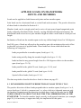
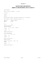
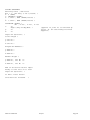
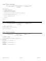
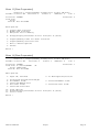
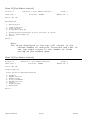
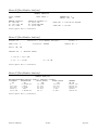
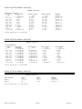
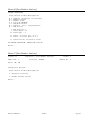
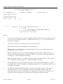
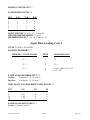
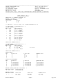
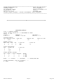
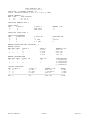
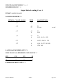
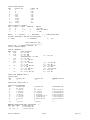
Section 25
QUESTION HEADINGS
DISPLAYED DURING DATA INPUT
Input TITLE ?
Units of Force & Length
Sections
?
Joints
?
Members
?
2?
kN,m
Existing Unit Weight = 23.6 kN/m3 (Constant for all Sections)
Unit Weight in kN,m3 (NewValue/V/Return) ? V
Section
Sec-1
Sec-2
.
.
Sec-n
Unit Wt kN/m3
? 23.1
? 23.2
? 23.5
Input OK (N/return)
?
SECTION DETAILS
E , Area , Inertia
Sec-1
3?
Sec-2
3?
:
Sec-n
3?
Input OK (N/return)
?
JOINT COORDINATES
X-C , Y-C
Jnt-1
2?
Jnt-2
2?
:
Jnt-n
2?
Input OK (N/return)
?
MEMBER DETAILS
Jnt1 , Jnt2 , Sec
Mem-1
3?
Mem-2
3?
:
Mem-n
3?
Input OK (N/return)
Skeleton-9 Manual
?
Preface
Page-63
SPRING CONSTANTS
Existing Value ; New Value
Nos = 1 ; How many (1 TO 9/return) ?
0- 0 (FREE)
1- INFINITY (FIXED)
2- 9.9E+09 ; NEW (VALUE/return) ?
:
n- 9.9E+09 ; NEW (VALUE/return) ?
SUPPORTED JOINTS ?
Jnt , X-res , Y-res , R-res
14?
Angle (Any-in-deg/Mem) ?
24?
:
n4?
Input OK (N/return)
Joint Hinges ?
(appears if joint no is followed by
letter 'A' for describing inclined
supports)
?
1-Jnt No ?
2-Jnt No ?
:
n-Jnt No ?
Hinged Bar-Members ?
1-Mem No ?
2-Mem No ?
:
n-Mem No ?
Member Hinges ?
1-Mem No , Jnt No
2-Mem No , Jnt No
:
n-Mem No , Jnt No
2?
2?
2?
End of Structure Details Input
Ready to Save Data on to Disk
Input OK (N/return)
?
To Exit: Press Return
Give New Data Filename
Skeleton-9 Manual
?
Preface
Page-64
LOADING CASE n
Input TITLE ?
Input Loading Case No ?
Include Self Weight (Y/N)
?
Input OK (N/return) ?
LOADED MEMBERS ?
1- Mem No , No of Loads 2?
1-Load-Type ? 1 or 11 or 21
Mem Length=
P , A 2?
Load Inclination: (if load
(0 to 360 DEG) ?
2-Load-Type ? 2 or 12 or 22
Mem Length=
N , P , A , B 4?
Load Inclination: (if load
(0 to 360 DEG) ?
:
n-Load-Type ? 3 or 13 or 23
Mem Length=
W ?
Load Inclination: (if load
(0 to 360 DEG) ?
2- Mem No , No of Loads 2?
1-Load-Type ? 4 or 14 or 24
Mem Length=
Q ?
Load Inclination: (if load
(0 to 360 DEG) ?
2-Load-Type ? 5 or 15 or 25
Mem Length=
W , A , B 3?
Load Inclination: (if load
(0 to 360 DEG) ?
:
n-Load-Type ? 6 or 16 or 26
Mem Length=
Q , Q , A , B 4?
Load Inclination: (if load
(0 to 360 DEG) ?
:
n- Mem No , No of Loads 2?
1-Load-Type ? 7 or 17 or 27
Mem Length=
W , A , B 3?
Load Inclination: (if load
(0 to 360 DEG) ?
2-Load-Type ? 8 or 18 or 28
Mem Length=
M , A 2?
3-Load-Type ? 9 or 19 or 29
Mem Length=
W , A , B 3?
Load Inclination: (if load
(0 to 360 DEG) ?
or 31 or 41
type 21)
or 32 or 42
type 22)
or 33 or 43
type 23)
or 34 or 44
type 24)
or 35 or 45
type 25)
or 36 or 46
type 26)
or 37 or 47
type 27)
or 38 or 48
or 39 or 49
type 29)
4-Load-Type ? 51
Mem Length=
Temp , Coeff 2?
5-Load-Type ? 52
Mem Length=
N , M , A , B
4?
6-Load-Type ? 53
Mem Length=
Lack of Fit ?
:
n-Load-Type ? 54
Skeleton-9 Manual
Preface
Page-65
Mem Length=
Strain ?
More Loads (Y/N) ?
(appears only if a Load-Type or MEM NO is input as 0; this
provides an exit when more than required LOADS/LOADEDMEMBERS have been input mistakenly)
Input OK (N/return) ?
Same-Load Member-Sets
?
NO OF MEMBERS IN SET 1 ARE ?
1- MEM NO ?
2- MEM NO ?
:
n- MEM NO ?
NO OF MEMBERS IN SET 2 ARE ?
1- MEM NO ?
-2- MEM NO ?
:
n- MEM NO ?
:
NO OF MEMBERS IN SET n ARE ?
1- MEM NO ?
2- MEM NO ?
:
n- MEM NO ?
Input OK (N/return) ?
HOW MANY LOADED/DISPLACED JOINTS ?
Jnt , Fx , Fy , M
12:
n-
4?
4?
Note:
To specify an imposed displacement
at a support, the value is followed
by the character 'D'.
4?
Input OK (N/return) ?
SAME LOAD JOINT-SETS ?
NO
12:
n-
OF JOINTS IN SET 1 ARE ?
JNT NO ?
JNT NO ?
NO
12:
n-
OF JOINTS IN SET 2 ARE ?
JNT NO ?
JNT NO ?
NO
12:
n-
OF JOINTS IN SET n ARE ?
JNT NO ?
JNT NO ?
JNT NO ?
JNT NO ?
JNT NO ?
End of Input for Load Case n
Ready to Save Data on to Disk
Input OK (N/return)
Skeleton-9 Manual
?
Preface
Page-66
Section 26
26- VARIOUS OPTION MENUS OF THE PROGRAM
Menu 1 [Master Options]
Techno Consultants Ltd
SKELETON-9: ANALYSIS OF PLANE FRAMEWORKS
Copyright
Dr S.U.R. Khan
MASTER-OPTIONS:
1- Data Preparation
2- Framework Analysis
3- Load Combination Analysis
4- Post Member Analysis
5- Change/Display-Filenames-in Data Drive/Dir A:
6- Alter Default Settings
7- Finish
Which ?
Menu 2 [Data Preparation]
Skeleton-9: Data Preparation
Main Options:
1- Prepare/Modify Structure Data
2- Prepare/Modify Loading Data
3- Print Structure &/or Load-Cases Data
4- Change/Display-Filenames-in Data Drive/Dir C:\SK9DATA\
5- Exit to MASTER Options
6- Make Copy of Structure &/or Load-Case Files
7- Finish
Which ?
Skeleton-9 Manual
Preface
Page-67
Menu 3 [Data Preparation]
Skeleton-9: Prepare/Modify Structure Data in & Units
Sections= 0
Joints= 0
Members= 0
Filename:
Main Options:
1- Prepare New Data
2- Modify/Examine Old Data
3- Edit/Save Data in Memory
4- Change/Display-Filenames-in Data Drive/Dir Y
5- Prepare/Modify Loading Data
6- Exit to MASTER Options
7- Finish
Which ?
Menu 4 [Data Preparation]
Skeleton-9: Prepare/Modify Structure Data in & Units
Sections= 0
Joints= 0
Members= 0
Filename:
To Exit: Press Return
Modify/Examine Other Structure:
Give its Filename ?
Menu 5 [Data Preparation]
Skeleton-9: Prepare/Modify Structure Data in & Units
Sections= 0
Joints= 0
Members= 0
Filename: FRAME1
FILENAME: FRAME1
Insert Additional Elements (Y/Return) ? Y
SECTIONS:
How Many to be Inserted ? 1
JOINTS:
How Many to be Inserted ? 1
MEMBERS:
How Many to be Inserted ? 1
Skeleton-9 Manual
Preface
Page-68
Menu 6 [Data Preparation]
Skeleton-9: Prepare/Modify Structure Data in KN & CM Units
Sections= 2
Joints= 5
Members= 4
Filename: FRAME1
Edit Options:
1- Input OK; Continue
2- To Main-Options/Re-Start
3- Change Title/Units/Unit-Weight
5- Joint Changes
4- Section Changes
6- Member Changes
7- Display/Print Structure Diagram
8- Spring Constants & Supports
9- Joint & Member Hinges
10- Print All/Part Input Details
11- Change/Display-Filenames-in Data Drive/Dir A:\J2535\
12- Save to Disk (Data in Memory)
NB
Structure Details Now Include All the Changes Made so far.
If in Doubt, Take Option 7 and/or 10.
Which ?
Menu 7 [Data Preparation]
Skeleton-9: Prepare/Modify Structure Data in KN & CM Units
Sections= 2
Joints= 5
Members= 4
Filename: FRAME1
OPTIONS TO PRINT:
1234567-
Entire Details
Structure Reference
Section Properties
Member Details
Joint Coordinates
Supports & Spring Constants
To Main-Options/Continue
Which ?
Skeleton-9 Manual
Preface
Page-69
Menu 8 [Data Preparation]
Skeleton-9: Prepare/Modify Structure Data in KN & CM Units
Sections= 2
Joints= 5
Members= 4
Filename: FRAME1
OPTIONS TO MODIFY:
1- Exit to Main-Options
2- Re-Define Details of SECTIONS
3- Add Up to 1 SECTIONS (Appears if SECTIONS can be added; see notes below Menu 10)
Which ?
Menu 9 [Data Preparation]
Skeleton-9: Prepare/Modify Structure Data in KN & CM Units
Sections= 2
Joints= 5
Members= 4
Filename: FRAME1
OPTIONS TO MODIFY:
1- Exit to Main-Options
2- Re-Define Details of JOINTS
3- Add Up to 1 JOINTS (Appears if JOINTS can be added; see notes below Menu 10)
Which ?
Menu 10 [Data Preparation]
Skeleton-9: Prepare/Modify Structure Data in KN & CM Units
Sections= 2
Joints= 5
Members= 4
Filename: FRAME1
OPTIONS TO MODIFY:
1- Exit to Main-Options
2- Re-Define Details of MEMBERS
3- Add Up to 1 MEMBERS (Appears if MEMBERS can be added; see notes below )
Which ?
Notes:
1-Addition of sections, joints and members via option3 of menus 8,9 and 10 respectively can take
place ONLY IF answer to INSERT ADDITIONAL
ELEMENTS (Y/N) ? has been Yes and the numbers to
be inserted has been defined beforehand via
menu-5
2-All newly added sections and joints should be
described/added (via option-3 of menus 8 and 9
respectively) BEFORE the member details which
refer to them.
Menu 11 [Data Preparation]
Skeleton-9: Prepare/Modify Structure Data in KN & CM Units
Sections= 2
Joints= 5
Members= 4
Skeleton-9 Manual
Preface
Page-70
Filename: FRAME1
EXISTING:
Title: EUROTRUCK DEVELOPMENT NEWBRIDGE
Units: KN
CM
OPTIONS:
1234-
Change Title
Change Units
Unit Weight of Sections
Exit
Which ?
Menu 12 [Data Preparation]
Skeleton-9: Prepare/Modify Structure Data in KN & CM Units
Sections= 2
Joints= 5
Members= 4
Filename: FRAME1
Existing Unit Weight = 7.697263E-05 KN/CM3 (Constant for all Sections)
Unit Weight in KN/CM3 (New Value/V/Return) ? V
Section
Sec- 1
Sec- 2
Unit Wt KN/CM3
? 1
? 2
Skeleton-9 Manual
Preface
Page-71
Menu 13 [Data Preparation]
Skeleton-9: Prepare/Modify Loading Data in KN & CM Units
SelfWt= 30.05199 KN
Sections= 2
Joints= 5
Members= 4
DoI= 1
Structure: FRAME1
Load File:
Title:
Self Wt: Not-Included
Load-Case= 0
Main Options:
1- Prepare New Load Case
2- Modify Old Load Case
3- Edit/Save Data in Memory
4- Change/Display-Filenames-in Data Drive/Dir A:\J2535\
5- Prepare/Modify Loads for Other Structure
6- Prepare/Modify Structure Data
7- Exit to Master Options
8- Finish
Which ?
Menu 14 [Data Preparation]
Skeleton-9: Prepare/Modify Loading Data in KN & CM Units
SelfWt= 30.05199 KN
Sections= 2
Joints= 5
Members= 4
DoI= 1
Structure:
Load File:
Title:
Self Wt:
FRAME1
A:\J2535\FRAME1
DEAD+LIVE
Not-Included
Load-Case= 1
.A1
Edit Options:
1- Input OK; Continue
34679-
Title/Load-Case-No/Self-Weight
All Member Loads
Same-Load-Member-Sets
All Joint Loads
Same-Load-Joint-Sets
2- To Main-Options/Re-Start
5- Selected Member Loads
8- Selected Joint Loads
10- Print Options
11- Change/Display-Filenames-in Data Drive/Dir A:\J2535\
12- Save to Disk
Which ?
Skeleton-9 Manual
Preface
Page-72
Menu 15 [Data Preparation]
Skeleton-9: Prepare/Modify Loading Data in KN & CM Units
SelfWt= 30.05199 KN
Sections= 2
Joints= 5
Members= 4
DoI= 1
Structure:
Load File:
Title:
Self Wt:
FRAME1
A:\J2535\FRAME1
DEAD+LIVE
Not-Included
Load-Case= 1
.A1
PRINT OPTIONS:
1234567-
All Input
Loading Reference
Member Loads
Same-Load Member-Sets
Joint Loads
Same-Load Joint-Sets
Exit
Which ?
Menu 16 [Data Preparation]
Skeleton-9: Prepare/Modify Loading Data in KN & CM Units
SelfWt= 30.05199 KN
Sections= 2
Joints= 5
Members= 4
DoI= 1
Structure:
Load File:
Title:
Self Wt:
FRAME1
A:\J2535\FRAME1
DEAD+LIVE
Not-Included
Load-Case= 1
.A1
OPTIONS:
1234-
Change Title
Change Loading Case No
Include/Not-Include Self Wt
Exit
Which ?
Menu 17 [Data Preparation]
Skeleton-9: Prepare/Modify Loading Data in KN & CM Units
SelfWt= 30.05199 KN
Sections= 2
Joints= 5
Members= 4
DoI= 1
Structure:
Load File:
Title:
Self Wt:
FRAME1
A:\J2535\FRAME1
DEAD+LIVE
Not-Included
Load-Case= 1
.A1
Include Self Weight (Y/N) ? Y
Skeleton-9 Manual
Preface
Page-73
Menu 18 [Data Preparation]
Skeleton-9: Data Preparation
Print Structure &/or Load-Cases Data
Options to Print:
12345-
Structure
Structure + Load-Cases
Load-Cases
Change/Display-Filenames-in Data Drive/Dir A:\J2535\
Exit to Main-Options
Which ?
Menu 19 [Data Preparation]
Skeleton-9: Data Preparation
Print Structure &/or Load-Cases Data
To Exit: Press Return
Give Name of the (Previous) Structure File:
? ........
Menu 20 [Data Preparation]
Skeleton-9: Data Preparation
Print Structure &/or Load-Cases Data
Load- Case Selection Options:
12345-
'1' to 'N' Inclusive
'N1' to 'N2' Inclusive
Random Numbers: N1,N2...NN
Change/Display-Filenames-in Data Drive/Dir A:\J2535\
Return to Main Options
Which ?
Skeleton-9 Manual
Preface
Page-74
Menu 21 [Data Preparation]
SKELETON-9: CREATE NEW-NAME DATA FILES
Old-Data in Memory:
New-Names for Saving:
Structure:
Structure:
Loading Case No: 0
Loading Case No: 0
=====================================================================
To Exit: Press RETURN
Give Name of the Old-Structure File ?
Menu 22 [Data Preparation]
SKELETON-9: CREATE NEW-NAME DATA FILES
Old-Data in Memory:
New-Names for Saving:
Structure: FRAME1
Structure: FRAME2
Loading Case No: 1
Loading Case No: 1
=====================================================================
OPTIONS:
1- Read: Other Old-Structure Data
2- Read: Other Old-Loading-Case
3- Change: New-Structure Name
4- Change: New-Loading-Case No
5- Save to Disc: Structure Data
6- Save to Disc: Loading-Case Data
7- Change/Display-Filenames-in Data Drive/Dir A:\J2535\
8- Exit to Master-Options
9- Finish
Which ?
Skeleton-9 Manual
Preface
Page-75
Menu 23 [Framework Analysis]
Skeleton-9: Framework Analysis
Main-Options:
1- Begin Framework Analysis
2- Print Last-Analysis-Copy
3- Change/Display-Filenames-in Data Drive/Dir A:\J2535\
4- Exit to MASTER Options
5- Finish
Which ?
Menu 24 [Framework Analysis]
Skeleton-9: Framework Analysis
Begin Framework Analysis
To Exit: Press Return
Give Name of the (Previous) Structure File:
? FRAME1..
Menu 25 [Framework Analysis]
Skeleton-9: Framework Analysis
Begin Framework Analysis
Load- Case Selection Options:
12345-
'1' to 'N' Inclusive
'N1' to 'N2' Inclusive
Random Numbers: N1,N2...NN
Change/Display-Filenames-in Data Drive/Dir A:\J2535\
Return to Main Options
Which ?
Skeleton-9 Manual
Preface
Page-76
Menu 26 [Framework Analysis]
Skeleton-9: Framework Analysis
Select Load-Case Numbers:
Option: '1' TO 'N' Inclusive
Input 'N' (1 to
99 )
?
Menu 27 [Framework Analysis]
Skeleton-9: Framework Analysis
Select Load-Case Numbers:
Option: 'N1' TO 'N2' Inclusive
Input 'N1','N2' (N2-N1< 99 )
2?
Menu 28 [Framework Analysis]
Skeleton-9: Framework Analysis
Select Load-Case Numbers:
Option: Random Numbers N1,N2....NN
How Many Load Cases (1 TO
Load-Case Number- 1
Load-Case Number- 2
.
.
Load-Case Number- n
Skeleton-9 Manual
99 )
? n
?
?
?
Preface
Page-77
Menu 29 [Framework Analysis]
Selection of Output-Contents:
Y 1- Heading (20-Define its Contents)
Y 2- Structure Diagram
Y 3- Structure Reference
Y 4- Structure Details
Y 5- Loading Reference
Y 6- Member & Joint Loads
Y 7- Joint Displacements
Y 8- Member Forces
N 9- Member Deformations
Y 10- Support Reactions
11- Decimals: Loads= 4 & Displacements= 6
12- 1st Page No= 1
13- Lines/Page= 60
14- Lines/Gap= 6
N 15- Send Output to Data Disk File: FRAME1.STR
16171819-
Reset: To Print All of 1-10
Reset: To Print None of 1-10
Selection OK; Proceed Further
Exit to Main-Options
To Toggle the Y/N Selection: Enter the List No
Which ?
Menu 30 [Framework Analysis]
Skeleton-9: Framework Analysis
Select Decimal Places:
Press Return To Exit/Main-Options
1- Loads: n
2- Displacements: n
Which ?
Menu 31 [Framework Analysis]
Skeleton-9: Framework Analysis
Decimal Places for Loads:
Present Value = n
Input New Value ( Between 1 & 7 ) ?
Skeleton-9 Manual
Preface
Page-78
Menu 32 [Framework Analysis]
Skeleton-9: Framework Analysis
Decimal Places for Displacements:
Present Value = n
Input New Value ( Between 1 & 7 ) ?
Menu 33 [Framework Analysis]
** HEADING CONTENTS **
JOB NO
DATE
PAGE NO
DESIGNER
PROJECT
Re-Define (Y/Return) ?
Menu 34 [Framework Analysis]
Skeleton-9: Framework Analysis
D.O.S. Error No = 53
Filename: A:\J2535\FRAME8
File Not Found
Press Space Bar to Continue
Skeleton-9 Manual
Preface
Page-79
Menu 35 [Load Combination Analysis]
Skeleton-9: Load Combination Analysis
Main Options:
1- Combine Load Cases & Analyse
2- Print Last-Analysis Copy
3- Change/Display-Filenames-in Data Drive/Dir A:\J2535\
4- Exit to MASTER Options
5- Finish
Which ?
Menu 36 [Load Combination Analysis]
Skeleton-9: Load Combination Analysis
Combine Load Cases & Analyse
To Exit: Press Return
Give Name of the (Previous) Structure File:
? ........
Menu 37 [Load Combination Analysis]
Skeleton-9: Load Combination Analysis
Combine Load Cases & Analyse
Load- Case Selection Options:
12345-
'1' to 'N' Inclusive
'N1' to 'N2' Inclusive
Random Numbers: N1,N2...NN
Change/Display-Filenames-in Data Drive/Dir A:\J2535\
Return to Main Options
Which ?
Menu 38 [Load Combination Analysis]
Skeleton-9: Load Combination Analysis
Select Load-Case Numbers:
Option: '1' TO 'N' Inclusive
Input 'N' (1 to
Skeleton-9 Manual
32 )
?
Preface
Page-80
Menu 39 [Load Combination Analysis]
Skeleton-9: Load Combination Analysis
How Many Combinations (40 Max, 0 TO Exit) ?
Menu 40 [Load Combination Analysis]
Skeleton-9: Load Combination Analysis
Structure: ......
No of Combinations= ..
Load-Cases Selected for 2 Combinations:
..
..
..
nn
Combination Analysis No n
Input Comb-Case No (1 TO 99, 0 TO Skip) ?
Skeleton-9 Manual
Preface
Page-81
Menu 41 [Load Combination Analysis]
Skeleton-9: Load Combination Analysis
Combination- 1
C:\SK9DATA\SPBLM2
.D1 is an Existing File:
for Previous Comb-Case No= 1
Options:
1234-
Over Write Existing File
Change Comb-Case No
Change/Display-Filenames-in Data Drive/Dir C:\SK9DATA\
Abort Entire Analysis/Exit
Which ?
Menu 42 [Load Combination Analysis]
Structure: FRAME1
Skeleton-9: Load Combination Analysis
No of Combinations= 2
Load-Cases Selected for 2 Combinations:
1
2
Combination Analysis No 1
Comb-Case No= 1
Title:
Input Title (60 Chrs Max)
? DEAD+LIVE+WIND
Menu 43 [Load Combination Analysis]
Skeleton-9: Load Combination Analysis
Structure: FRAME1
No of Combinations= 2
Load-Cases Selected for 2 Combinations:
1
2
Combination Analysis No 1
Comb-Case No= 1
Title: DEAD+LIVE+WIND
How Many Load-Cases to be Combined (0 TO Skip, 2 Max) ?
Skeleton-9 Manual
Preface
Page-82
Menu 44 [Load Combination Analysis]
Skeleton-9: Load Combination Analysis
Structure: FRAME1
No of Combinations= 2
Load-Cases Selected for 2 Combinations:
1
2
3
Combination Analysis No 1
Comb-Case No= 1
Title: DEAD+LIVE+WIND
No of Load-Cases= 2
1 - Load-Case , Factor
2 - Load-Case , Factor
3 - Load-Case , Factor
2? 1,1.4
2? 2,1.6
2? 3,1.2
End of Input for Analysis No 1 ;
Press RETURN to Continue
Menu 45 [Load Combination Analysis]
Selection of Output-Contents:
Y 1- Heading (20-Define its Contents)
Y 2- Structure Diagram
Y 3- Structure Reference
Y 4- Structure Details
Y 5- Loading Reference
Y 6- Member & Joint Loads
Y 7- Joint Displacements
Y 8- Member Forces
N 9- Member Deformations
Y10- Support Reactions
11- Decimals: Loads= 4 & Displacements= 6
12- 1st Page No= 1
13- Lines/Page= 60
14- Lines/Gap= 6
N 15- Send Output to Data Disk File: FRAME1.MIX
16171819-
Reset: To Print All of 1-10
Reset: To Print None of 1-10
Selection OK; Proceed Further
Exit to Main-Options
To Toggle the Y/N Selection: Enter the List No
Which ?
Skeleton-9 Manual
Preface
Page-83
Menu 46 [Load Combination Analysis]
Skeleton-9: Load Combination Analysis
Structure: FRAME1
Load-Cases Selected for 2 Combinations:
1
2
3
Comb-Case
1
2
Numbers
for 2 Combinations:
Options:
1234-
Input OK; Continue to Analyse
Examine/Modify Combination Data
Examine/Modify Output Selection
Abort Analysis/To Master-Options
Which ?
Menu 47 [Load Combination Analysis]
Combination Analysis No
1
Comb-Case No= 2
Title: DEAD+LIVE+WIND
Load-Case & Combination-Factors:
1: 1 X 1.4
2: 2 X 1.6
=====================================================================
EXAMINE/MODIFY OPTIONS: 1- Display Next Combination
2- Title
3- Comb-Case No
4- Load Factors
5- Exit
Which ?
Menu 48 [Load Combination Analysis]
Skeleton-9: Load Combination Analysis
Structure: FRAME1
Load-Cases Selected for 2 Combinations:
1
2
3
Comb-Case
1
2
Numbers
for 2 Combinations:
Combination- 1
Existing Comb-Case No= 1
New Comb-Case No (1 TO 99) ?
Menu 49 [Load Combination Analysis]
Combination Analysis No
1
Comb-Case No= 2
Title: DEAD+LIVE+WIND
Load-Case & Combination-Factors:
1: 1 X 1.4
2: 2 X 1.6
=====================================================================
Re-Define Load-Factors:
How Many to be Re-Defined ( 2 Max, 0 TO EXIT ) ?
Skeleton-9 Manual
Preface
Page-84
Menu 50 [Load Combination Analysis]
Combination Analysis No
1
Comb-Case No= 2
Title: DEAD+LIVE+WIND
Load-Case & Combination-Factors:
1: 1 X 1.4
2: 2 X 1.6
=====================================================================
Factors to be Re-Defined= 2
2 - No , Load-Case , Factor 3? 2,2,1.1
Menu 51 [Load Combination Analysis]
Skeleton-9: Load Combination Analysis
Abort the Entire Analysis/Exit:
Are You Sure (Y/Return) ?
Skeleton-9 Manual
Preface
Page-85
Menu 52 [Post Member Analysis]
Skeleton-9: Post Member Analysis
Main Options:
1- Post Member-Analysis: Interactive
2- Post Member-Analysis: Automatic
3- Change/Display-Filenames-in Data Drive/Dir A:\J2535\
4- Exit to MASTER Options
5- Finish
Which ?
Menu 53 [Post Member Analysis]
Points= 0
Skeleton-9: Post Member Analysis
LOAD Case: 0
Structure:
Loads= 0
Member No: 0
Units: ,
How Many Analysis Points ( 11 to 46 ) ? 11
Menu 54 [Post Member Analysis]
Points= 11
Skeleton-9: Post Member Analysis
LOAD Case: 0
Structure:
Loads= 0
Member No: 0
Units: ,
Structure Name ?
Menu 55 [Post Member Analysis]
Points= 11
Skeleton-9: Post Member Analysis
LOAD Case: 0
Structure: FRAME1
Loads= 0
Member No: 0
Units: ,
Load/Comb Case No? 1
Skeleton-9 Manual
Preface
Page-86
Menu 56 [Post Member Analysis]
Points= 11
Skeleton-9: Post Member Analysis
LOAD Case: 1
Structure: FRAME1
Loads= 0
Member No: 0
Units: ,
Member No? 2
Menu 57 [Post Member Analysis]
Points= 11
Skeleton-9: Post Member Analysis
LOAD Case: 1
Structure: FRAME1
Loads= 0
Member No: 2
Units: ,
New-Analysis Options:
1- New Structure Name
2- New LOAD/COMB Case No
3- New Member No
4- Change-Case: LOAD-><-COMB
5- Fetch Data & Analyse
6- Change/Display-Filenames-in Data Drive/Dir A:\J2535\
7- Exit to MASTER Options
Which ?
Skeleton-9 Manual
Preface
Page-87
Menu 58 [Post Member Analysis]
Points= 11
Skeleton-9: Post Member Analysis
LOAD Case: 1
Structure: FRAME1
Loads= 1
Member No: 2
Units: KN, CM
Main-Options:
1- New Analysis
2- Display Options
3- Print Options
4- Change-Data Options
5- Change/Display-Filenames-in Data Drive/Dir A:\J2535\
6- Exit to Master-Options
7- Finish
Which ?
Note:
The value displayed in the top left corner is the
chosen number of analysis locations and that in
the top right corner is the number of loads
acting on the member span.
Menu 59 [Post Member Analysis]
Points= 11
Skeleton-9: Post Member Analysis
LOAD Case: 1
Structure: FRAME1
Loads= 1
Member No: 2
Units: KN, CM
Display Options:
Press Return To Exit/Main-Options
12345678-
Heading
Member Details
Member Loads
D-A-S-M DIAGRAM
Max/Min Results
Results
Displacements
End Forces
Which ?
Skeleton-9 Manual
Preface
Page-88
Menu 60 [Post Member Analysis]
MEMBER ANALYSIS
FILE: FRAME1
REF:
LOAD CASE: 1
MEMBER DETAILS:
X= 1150 CM
L= 1167.745 CM
A= 85.5 CM2
ANALYSIS
Y= 202.8
E= 21000
I= 24329
POINTS= 11
CM
KN/CM2
CM4
MEMBER NO: 2
UNITS: KN , CM
UNIT WT= 7.697263E-05 KN/CM3
SELF WT= 7.685 KN
Press Space Bar to Continue
Menu 61 [Post Member Analysis]
Points= 11
Skeleton-9: Post Member Analysis
LOAD Case: 1
Structure: FRAME1
Loads= 1
Member No: 2
Units: KN, CM
DETAILS OF
1
APPLIED LOADS:
1- T43 W = 103.5 KN
2- T1
P = 30 KN
A = 20 CM
Press Space Bar to Continue
Menu 62 [Post Member Analysis]
MEMBER ANALYSIS
MAXIMUM/MINIMUM RESULTS FROM 11 ANALYSIS POINTS:
DISTANCE
DEFLECTION
AXIAL-FORCE
SHEAR-FORCE
CM
CM
KN
KN
0
-1.3362E-06
68.674>
92.987>
116.774
-.6214<
66.877
82.794
817.421
1.6342>
56.092
21.637
1050.97
.9503
52.497
1.252
1167.745
1.8815E-06
50.7<
-8.941<
MOMENT
KN CM
-33977.94<
-23714.65
12870.09
15543>
15094.07
Press Space Bar to Continue
Skeleton-9 Manual
Preface
Page-89
Menu 63 [Post Member Analysis]
MEMBER ANALYSIS
ANALYSIS RESULTS:
DISTANCE
DEFLECTION
CM
CM
0
-1.3362E-06
116.774
-.6214<
233.549
-.6071
350.323
-.1995
467.098
.3913
583.872
.9864
700.647
1.439
817.421
1.6342>
934.196
1.4885
1050.97
.9503
1167.745
1.8815E-06
AXIAL-FORCE
KN
68.674>
66.877
65.079
63.282
61.484
59.687
57.889
56.092
54.294
52.497
50.7<
SHEAR-FORCE
KN
92.987>
82.794
72.601
62.408
52.216
42.023
31.83
21.637
11.445
1.252
-8.941<
MOMENT
KN CM
-33977.94<
-23714.65
-14641.53
-6758.735
-66.13
5436.178
9748.273
12870.09
14801.67
15543>
15094.07
Press Space Bar to Continue
Menu 64 [Post Member Analysis]
MEMBER ANALYSIS
DISPLACEMENTS:
DISTANCE
ROTATION
CM
RADIANS
0
-8.8018E-03
116.774
-2.2313E-03
233.549
2.1295E-03
350.323
4.5524E-03
467.098
5.3097E-03
583.872
4.6733E-03
700.647
2.9154E-03
817.421
3.0786E-04
934.196
-2.8772E-03
1050.97
-6.3677E-03
1167.745
-9.8916E-03
AXIAL-DEFL.
CM
0
-4.4079E-03
-8.699E-03
-1.2873E-02
-1.693E-02
-2.0871E-02
-2.4694E-02
-2.8401E-02
-.032
-3.5463E-02
-3.8819E-02
PREP.-DEFL.
CM
-1.3362E-06
-.6214
-.6071
-.1995
.3913
.9864
1.439
1.6342
1.4885
.9503
1.8815E-06
TOTAL-DEFL.
CM
1.3362E-06
.6214
.6072
.1999
.3916
.9866
1.4393
1.6344
1.4888
.951
3.8819E-02
Press Space Bar to Continue
Menu 65 [Post Member Analysis]
MEMBER ANALYSIS
END-FORCES:
END-1
END-2
AXIAL
KN
68.674
50.7
SHEAR
KN
92.987
-8.941
MOMENT
KN CM
-33977.94
15094.07
Press Space Bar to Continue
Skeleton-9 Manual
Preface
Page-90
Menu 66 [Post Member Analysis]
OUTPUT SELECTION:
Press Return To Exit/Main-Options
N
N
N
Y
Y
N
N
1
2
3
4
5
6
7
-Heading (14-Define its Contents)
-Member Details
-Member Loads
-D-A-S-M DIAGRAM
-Max/Min Results
-Results (N 99- Displacements)
-End-Forces
8 -New Page No= 1
9 -Lines/Page = 60
10 -Lines/Gap = 6
11 -Reset: To Print All of 1-7
12 -Reset: To Print None of 1-7
13 -Selection OK; Proceed to Print
TO CHANGE SELECTION: ENTER THE LIST NO
Which ?
Menu 67 [Post Member Analysis]
Points= 11
Skeleton-9: Post Member Analysis
LOAD Case: 1
Structure: FRAME1
Loads= 1
Member No: 2
Units: KN, CM
Change-Data Options:
Press Return To Exit/Main-Options
1- Analysis Locations
2- Change Decimal Places
Which ?
Skeleton-9 Manual
Preface
Page-91
Menu 68 [Post Member Analysis]
Points= 11
LOAD Case: 1
Skeleton-9: Post Member Analysis
Structure: FRAME1
Loads= 1
Member No: 2
Units: KN, CM
No of Present ANALYSIS LOCATIONS = 11
Options:
Press Return To Exit/Main-Options
1- Change the No of Locations
2- Modify/Define Locations
3- Display Existing Locations
Which ?
Menu 69 [Post Member Analysis]
Points= 11
LOAD Case: 1
Skeleton-9: Post Member Analysis
Structure: FRAME1
Loads= 1
Member No: 2
Units: KN, CM
How Many Analysis Points ( 11 to 46 ) ? 11
Skeleton-9 Manual
Preface
Page-92
Menu 70 [Post Member Analysis]
Points= 11
Skeleton-9: Post Member Analysis
LOAD Case: 1
Structure: FRAME1
Loads= 1
Member No: 2
Units: KN, CM
Modify Define Analysis Locations:
Type:
A New-Value to Change the Existing
Any Letter
to Exit
(Return)
to Display/Modify the Next Location
=====================================================================
Member Length = 1167.745
Location- 1 :
Existing Distance = 116.774
Input New Distance ?
Menu 71 [Post Member Analysis]
Points= 11
Skeleton-9: Post Member Analysis
LOAD Case: 1
Structure: FRAME1
Loads= 1
Member No: 2
Units: KN, CM
ANALYSIS LOCATIONS
1 - 0 CM
2 - 116.774 CM
3 - 233.549 CM
4 - 350.323 CM
5 - 467.098 CM
6 - 583.872 CM
7 - 700.647 CM
8 - 817.421 CM
9 - 934.196 CM
10 - 1050.97 CM
11 - 1167.745 CM
Press Space Bar to Continue
Skeleton-9 Manual
Preface
Page-93
Menu 72 [Post Member Analysis]
Skeleton-9: Post Member Analysis
Auto Analysis Options:
1- Start New Analyses
2- Resume Last/Unfinished Analyses
3- Exit to Main-Options
Which ?
Menu 73 [Post Member Analysis]
Skeleton-9: Auto Member Analysis Output
Load-Cases= 0
Comb-Cases= 0
Structure:
No of Members= 0
No of Output-Types= 1
To Exit: Press Return
Give Name of (Previous) Structure
File ?
Menu 74 [Post Member Analysis]
Skeleton-9: Auto Member Analysis Output
Load-Cases= 0
Comb-Cases= 0
Structure: FRAME1
No of Members= 4
No of Output-Types= 1
Structure File: FRAME1
Option to Select Load-Cases
12345-
'1' TO 'N' Inclusive
'N1' TO N2' Inclusive
Random Numbers: N1,N2...NN
Change/Display-Filenames-in Data Drive/Dir A:\J2535\
Exit
Which ?
Skeleton-9 Manual
Preface
Page-94
Menu 75 [Post Member Analysis]
Skeleton-9: Auto Member Analysis Output
Load-Cases= 2
Comb-Cases= 0
Structure: FRAME1
No of Members= 4
No of Output-Types= 1
Structure File: FRAME1
Option to Select Comb-Cases
12345-
'1' TO 'N' Inclusive
'N1' TO N2' Inclusive
Random Numbers: N1,N2...NN
Change/Display-Filenames-in Data Drive/Dir A:\J2535\
Exit
Which ?
Menu 76 [Post Member Analysis]
Skeleton-9: Auto Member Analysis Output
Load-Cases= 2
Comb-Cases= 0
Structure: FRAME1
No of Members= 4
No of Output-Types= 1
Pagination Data:
1- Ist Page No= 1
2- Lines/Page = 60
3- Lines/Gap
= 6
4- Selection OK ; Exit
Which ?
Menu 77 [Post Member Analysis]
Skeleton-9: Auto Member Analysis Output
Load-Cases= 2
Comb-Cases= 0
Structure: FRAME1
No of Members= 4
No of Output-Types= 1
Number of Output-Types:
Existing = 1
How Many (1 to 9/Return) ?
Skeleton-9 Manual
Preface
Page-95
Menu 78 [Post Member Analysis]
Details of Output-Type
1
Press Return To Exit/Main-Options
N
N
N
N
Y
Y
N
N
1
2
3
4
5
6
7
8
9
10
-
Begin Member Output on a New Page
Heading
Member Details
Member Loads
D-A-S-M Diagram
Max/Min Results
Results (N 99- Displacements)
End-Forces
No of Analysis Locations= 11
Decimals: Loads= 3
Displacements= 4
Analysis Locations= 3
11 - Reset: To Print All of 1-8
12 - Reset: To Print None of 1-8
13 - Display/Modify Other Output-Type
TO Change Selection: Enter the List No
Which ?
Menu 79 [Post Member Analysis]
Skeleton-9: Auto Member Analysis Output
Load-Cases= 2
Comb-Cases= 0
Structure: FRAME1
No of Members= 4
No of Output-Types= 1
OUTPUT CONTENTS OF MEMBER ANALYSES:
Assign Members to: Output-Type- 1
1- Assign Members: 1 TO N1 Inclusive
2- Assign Members: N1 TO N2 Inclusive
3- Assign Members: Selective N1,N2,....
4- Change/Next Output-Type
5- Modify/Examine Output-Type- 1
6- Exit
Which ?
Skeleton-9 Manual
Preface
Page-96
Menu 80 [Post Member Analysis]
Skeleton-9: Auto Member Analysis Output
Load-Cases= 2
Comb-Cases= 0
Structure: FRAME1
No of Members= 4
No of Output-Types= 1
Assign Members to: Output-Type- 1
Members 1 TO N1 Inclusive
Input N1 ? 2
Menu 81 [Post Member Analysis]
Skeleton-9: Auto Member Analysis Output
Load-Cases= 2
Comb-Cases= 0
Structure: FRAME1
Existing Output-Type =
New Output-Type ( 0
to
No of Members= 4
No of Output-Types= 1
1
1 ) ?
Note:
Compared with menu-85, the above appears when
assigning output-types to members. Here the
OUTPYT-TYPE (assigned to members can be 0
(zero), meaning no output required for the
member.
Skeleton-9 Manual
Preface
Page-97
Menu 82 [Post Member Analysis]
Skeleton-9: Auto Member Analysis Output
Load-Cases= 2
Comb-Cases= 0
Structure: FRAME1
No of Members= 4
No of Output-Types= 1
MAIN-OPTIONS:
1- Selection OK; Begin Auto Analyses
2- Send Output to Disk File: FRAME1.MEM
[No]
3- Display Selection
4- Modify Selection
5- Re-Start/Define Selection Anew
6- Change/Display-Filenames-in Data Drive/Dir A:\J2535\
7- Exit to Master-Options
8- Finish
Which ?
Menu 83 [Post Member Analysis]
Skeleton-9: Auto Member Analysis Output
Load-Cases= 2
Comb-Cases= 0
Structure: FRAME1
No of Members= 4
No of Output-Types= 1
DISPLAY OPTIONS:
1- Pagination Data
2- Selected Load & Comb Cases
3- Output-Type for Each Member
4- Details of Each Output-Type
5- Exit
Which ?
Skeleton-9 Manual
Preface
Page-98
Menu 84 [Post Member Analysis]
Skeleton-9: Auto Member Analysis Output
Load-Cases= 2
Comb-Cases= 0
Structure: FRAME1
No of Members= 4
No of Output-Types= 1
Modify/Change Options:
1- Pagination Data
2- Chosen Load/Comb Cases
3- Output-Type for Each Member
4- No of Output-Types
5- Contents of Output-Types
6- Exit
Which ?
Menu 85 [Post Member Analysis]
Skeleton-9: Auto Member Analysis Output
Load-Cases= 2
Comb-Cases= 0
Structure: FRAME1
Existing Output-Type =
1
New Output-Type ( 1
to
No of Members= 4
No of Output-Types= f
f ) ?
Note:
Compared with menu-81, the above appears when contents
of output types are being displayed for
modification/examination. Here a 0 (zero)
OUTPUT-TYPE cannot be displayed/modified.
Skeleton-9 Manual
Preface
Page-99
Menu 86 [Post Member Analysis]
Skeleton-9: Auto Member Analysis
** Progress Report **
No of Members= 4
Structure: FRAME1
Output Types= 1
--------------------------------------------------------------------Selected Load-Cases:
1
2
Selected Comb-Cases:
Members-Output Types:
1-1
2-1
3-0
4-0
--------------------------------------------------------------------Options: 1- To Prompt Each Analysis:Y/N
2- To Pause
3- To Stop & Continue Later
4- To Abort/Re-Start Afresh
Press Selection to Interrupt
Notes:1-
To select one of the above four options, a flashing display of about six seconds appears on the
screen before each member analysis. To make a selection, key 1, 2, 3 or 4 is pressed while
the display is flashing.
2-
A Yes or No in option-1 is indicated by Y or N shown in inverse.
When auto analysis starts, the default selection is always N.
When option-1 is pressed (during the flashing display of about six seconds), the selection
changes from N to Y or Y to N.
When the prompt selection is Y, the program stops after each member analysis. The next
analysis starts when prompted by pressing ANY KEY. The selection can be changed to N by
pressing key '1' while the display is flashing.
When the prompt selection is N, member analyses continue one after another. The selection
can be changed to Y by pressing key '1' while the display is flashing.
3-
The PAUSE option-2 stops the program execution. Pressing the SPACE BAR re-starts the
next analysis but, before this happens, the flashing display of six seconds allows options 1 to 4
to be taken, if required.
4-
The STOP & CONTINUE LATER option-3 ends the auto member analyses. The stage to
which the analyses have been completed is stored in the data file AUTO)( so that the
remaining analyses can be re-started later (by taking option-2 of menu-76). If desired, the
computer can be switched off (or used for some other purpose) after this option.
Skeleton-9 Manual
Preface
Page-100
5-
The ABORT/RE-START AFRESH option-4 aborts the program execution. Details of the auto
selection, however, remain intact in the data disc file AUTO)(. If required, member analyses
can be re-started from the very beginning of the auto selection by taking option-2 of menu-72.
Skeleton-9 Manual
Preface
Page-101
Menu 87 [Default Settings]
SKELETON DEFAULT SETTINGS:
1- Default Output Items for Frame
Analyses
2- Default Output Items for Member Analyses
3- Default Unit Weight [ 23.6 ]
4- Disk Drive/Dir for SKELETON Programs [
]
5- Maximum Elements in Member Loads Vector [ 2000 ]
6- VIDEO File Items [ 2
640
200
80
0
2
1.65 ]
7- Settings OK; Exit to Master Options
Which ?
Menu 88 [Default Settings]
Y 1Y 2Y 3Y 4Y 5Y 6Y 7Y 8N 9Y 101112141617181920-
Default Output Items for Frame Analyses
Heading
Structure Diagram
Structure Reference
Structure Details
Loading Reference
Member & Joint Loads
Joint Displacements
Member Forces
Member Deformations
Support Reactions
Decimals: Loads= 4 & Displacements= 6
1st Page No= 1
13- Lines/Diag= 31
Lines/Page = 60
15- Lines/Gap = 6
Characters/Left-Margin= 10
Reset: To Print All of 1-10
Reset: To Print None of 1-10
Selection OK; Save it Now
Exit to Master-Options
To Toggle the Y/N Selection: Enter the List No
Which ?
Skeleton-9 Manual
Preface
Page-102
Menu 89 [Default Settings]
MASTER-OUTPUT SELECTION
1st Page No:
Existing Value = 1
Input New Value ( Between 1 to 700 ) ? 21
Menu 90 [Default Settings]
MASTER-OUTPUT SELECTION
No of Lines/Diagram:
Existing Value = 31
Input New Value ( Between 1 to 99 ) ? 17
Menu 91 [Default Settings]
MASTER-OUTPUT SELECTION
Characters per Left-Margin:
Existing Value = 5
Input New Value ( Between 4 to 20 ) ? 10
Skeleton-9 Manual
Preface
Page-103
Menu 92 [Default Settings]
Default Output Items for Member Analyses
N
N
N
N
Y
Y
N
N
1
2
3
4
5
6
7
8
9
10
11
13
15
-
Begin Member Output on a New Page
Heading
Member Details
Member Loads
D-A-S-M Diagram
Max/Min Results
Results (N 99- Displacements)
End-Forces
No of Analysis Locations= 11
Decimals: Loads= 3 ; Displacements= 4 ; Analysis Locations= 3
1st Page No= 1
12 - Lines/Page= 60
Lines/Gap= 6
14 - Lines/Diagram= 16
Characters/Left-Margin= 5
16
17
18
19
-
Reset: To Print All of 1-8
Reset: To Print None of 1-8
Selection OK; Save it Now
Exit to Master-Options
To Toggle the Y/N Selection; Enter the List No
Which ?
Menu 93 [Default Settings]
Post Member Analysis
Default Master Output Selection
Select Decimal Places:
Press Return To Exit/Main-Options
1- Loads ( 3 )
2- Displacements ( 4 )
3- Analysis Locations ( 3 )
Which ?
Skeleton-9 Manual
Preface
Page-104
Menu 94 [Default Settings]
Post Member Analysis
Default Master Output Selection
Decimal Places for Loads:
Present Value = 3
Input New Value ( Between
1
&
7 ) ?
Menu 95 [Default Settings]
Post Member Analysis
Default Master Output Selection
Decimal Places for Displacements:
Present Value = 4
Input New Value ( Between
1
&
7 ) ?
Menu 96 [Default Settings]
Post Member Analysis
Default Master Output Selection
Decimal Places for Analysis Locations:
Present Value = 3
Input New Value ( Between
Skeleton-9 Manual
3
&
7 ) ?
Preface
Page-105
Menu 97 [Default Settings]
Techno Consultants Ltd
SKELETON-9: ANALYSIS OF PLANE FRAMEWORKS
Copyright
Dr S.U.R. Khan
Existing Default Unit-Weight = 23.6
Re-Define (Y/Return) ? Y
Input New Default Value ? 10.8
Menu 98 [Default Settings]
Techno Consultants Ltd
SKELETON-9: ANALYSIS OF PLANE FRAMEWORKS
Copyright
Dr S.U.R. Khan
Existing Program Drive/Dir is
Change (Y/Return) ? Y
Specify New Program Drive/Dir ?
N.B.
The program disk drive is nearly always the DEFAULT Drive and its description is usually a Null String. In normal
use, just press RETURN to specify this drive.
Skeleton-9 Manual
Preface
Page-106
Menu 99 [Default Settings]
Techno Consultants Ltd
SKELETON-9: ANALYSIS OF PLANE FRAMEWORKS
Copyright
Dr S.U.R. Khan
Existing Maximum Elements in Member Load Vector
2000
Re-Define (Y/Return) ? Y
Specify New Value (1000 min) ? 3000
Menu 100 [Default Settings]
Techno Consultants Ltd
SKELETON-9: ANALYSIS OF PLANE FRAMEWORKS
Copyright
Dr S.U.R. Khan
Mode, X-res, Y-res, LMarg, TMarg, Joint, AspectR
Existing VIDEO File Items
12 , 720 , 348 , 120 , 0 ,
4 ,
1.66
Re-Define (Y/Return) ? Y
New Items
7? 12,720,348,120,0,4,1.66
Skeleton-9 Manual
Preface
Page-107
150
SAMPLE PROBLEM 1
A Framework
and its
Loading Case 1
for
Analysis by Skeleton
308
2.75 KN
1.95 kN
0.008
kN/cm
0.005
kN/cm
3.85 KN
110
280
320
375
W=11.5 kN
W=11.5 kN
W=11.5 kN
W=10 kN
W=10 kN
W=10 kN
135
135
126
93
3.87 KN
200
3.87 KN
93
Skeleton-9 Manual
Preface
135
93
Page-108
0.006
kN/cm
Linearly varying distributed
load parallel to Global
Y-axis
Linearly varying distribu ted load
acting inclined at an ang le
of 320° to member span
Ø=320°
0.01
kN/cm
0.01
kN/cm
Horizontal UDL
of 2.25 kN
310
0.02
kN/cm
257
70
Distributed load of 0.02 kN/cm
acting along the centre-l ine
of the member
62
Loading Case 2
Linearly varying
distributed total
load of 3 kN
acting at an
angle of
130°
180
380
Ø=130°
Ø=46°
1 kN
478
554
1 kN
1 kN
1 kN
1 kN
1 kN
Ø=300° 40
100
Ø=55°
110
Skeleton-9 Manual
2 kN
Ø=225°
2 kN
2 kN
Preface
10 kN
6 kN
42
75
8 kN UDL
acting inclined
at an anlge of
225 °
2 kN
48
1.5 kN UDL
along member
centre line
7 kN UDL
acting inclined
at an angle of
55 °
3.7 kN
M=6 kN cm
180
5 kN linearly
distributed load
acting at an
angle of
300°
65
160
60
28
165
Horizontal distributed
load at 0.015 kN/cm
Horizontal
UDL of
1.395 kN
Ø=234°
4 kN
65
65
40
1 kN
2.5 kN
7 numbers equi-distant
point loads acting along
the member centre -line
260
Horizontal distributed
load at 0.015 kN/cm
5 numbers 1 kN equidistan t
point loads inclined at
an anle of 46 °
Page-109
Skeleton-9 Manual
Preface
Page-110
NUMBERING OF JOINTS,
MEMBERS & SECTIONS FOR AN ALYSIS
21
M26
1197
M25
S2
S2
M24
S2
M22
S2
M27
S4
13
M16
S1
M3
S3
Origin
Skeleton-9 Manual
M20
S2
16
3
295.5
363
Preface
326
200
5
M8
S3
6
2
228
M13
S1
M6
S3
7
M9
S3
M7
S3
M5
S3
M12
S1
M4
S3
M1
S3
M11
S1
1
93
M18
S1
15
M2
S3
9
8
14
M17
S1
M10
S3
M15
S1
419
12
11
M14
10
S1
M19
S2
739
M23
S2
17
M21
S2
18
1047
20
19
4
498
591
Page-111
SAMPLE PROBLEM 1
AN EXAMPLE SHOWING INPUT OF
FRAME AND LOADING DETAILS
TITLE: SAMPELE PROBLEM 1
UNITS ? KN,CM
SECTIONS ? 4
JOINTS ? 21
MEMBERS ? 27
SEC
MODULUS
AREA
1
21000
28.4
2
21000
41.8
3
21000
32.3
4
21000
95
MEMBER DETAILS
MEM JNT1
JNT2
1
1
8
2
8
9
3
9
11
4
2
7
5
7
12
6
3
6
7
6
13
8
4
5
9
5
15
10
15
14
11
8
7
12
7
6
13
6
5
14
10
11
15
11
12
16
12
13
17
13
14
18
14
16
19
10
9
20
16
15
21
10
18
22
18
19
23
16
17
24
17
20
25
20
21
26
19
21
27
18
17
Skeleton-9 Manual
INERTIA
2867
6481
2356
27329
JOINT COORDIATES
JNT
X-C
Y-C
1
93
0
2
228
0
3
363
0
4
498
0
5
498
200
6
363
200
7
228
200
8
93
200
9
93
326
10
0
419
11
93
419
12
228
419
14
363
419
14
498
419
15
498
326
16
591
419
17
591
739
18
0
739
19
0
1047
20
591
1047
21
295.5
1197
SEC
3
3
3
3
3
3
3
3
3
3
1
1
1
1
1
1
1
1
2
2
2
2
2
2
2
2
4
Preface
Page-112
SPRING CONSTANTS ? 1
SUPPORTED JOINTS ? 4
JNT
4
3
2
1
X-R
Y-R
R-R
1
1
1
1
1
1
1
1
0
1
1
0
JOINT HINGES ? 4 at 11, 12, 13 and 14
HINGED BAR MEMBERS ? 1 at 27
MEMBER HINGES ? 2 at 19, 9 and 20, 15
Input Data Loading Case 1
TITLE ? CASE-1 LOADING
LOADED MEMBERS ? 3
MEM NO , NO OF LOADS
TYPE
LOAD DETAILS
11, 1
3
10
15, 1
3
11.5
27, 2
6
1
0.005, 0.008, 110, 375
1.95, 280
SAME LOAD MEMBER-SETS ? 2
1st Set:
3 members 11, 12 and 13
2nd Set:
3 members 15, 16 and 17
HOW MANY LOADED/DISPLAYED JOINTS ? 3
JNT
FX
FY
M
8
18
19
3.87
3.85
2.75
0
0
0
0
0
0
SAME-LOAD JOINT SETS ? 1
1st Set: 2 joints 8 and 10
Skeleton-9 Manual
Preface
Page-113
Input Data Loading Case 2
TITLE ? CASE-2 LOADING
LOADED MEMBERS ? 17
MEM NO , NO OF LOADS
TYPE
LOAD DETAILS
27, 2
22
29
5, 1, 180, 380
3, 478, 554
at 46°
at 130°
26, 2
33
46
2.25
0.01, 0.006, 70, 310
25, 1
26
0.02, 0.01, 62, 257
24, 1
14
-0.02
22, 1
34
0.015
23, 1
42
7, 1, 40, 260
15, 1
1
2.5, 65
16, 1
11
-4, 60
17, 1
21
3.7, 65
20, 2
41
31
10, 75
6, 42
11, 1
27
5, 28, 100
at 300°
12, 1
25
7, 40, 110
at 55°
13, 1
23
8
1, 2
34
45
0.015
1.5, 48, 165
6, 1
2
4, -2, 65, 180
8, 1
8
6, 160
19, 1
33
1.395
at 320°
at 234°
at 225°
SAME LOAD MEMBER-SETS ? 1
1st Set:
3 members 22, 21, 2
HOW MANY LOADED/DISPLAYED JOINTS ? 0
SAME-LOAD JOINT SETS ? 0
Skeleton-9 Manual
Preface
Page-114
=====================================================================
TECHNO CONSULTANTS LTD
PROG: SK9/IBM 880113
PORTLAND HOUSE
JOB NO:EXAMPLE 1
103 PORTLAND STREET
DATE:30 SEPTEMBER 1988
MANCHESTER M1 6DF
PAGE NO:
TEL 061 236 0104
DESIGNER:SURK
PROJECT:SAMPLE PROBLEM 1 FOR ANALYSIS BY SKELETON-9
=====================================================================
STRUCTURE DETAILS
=================
FILE: C:\MANUAL\SAPBLM1
TITLE: SAMPLE PROBLEM 1
UNITS: KN , CM
JOINTS= 21
MEMBERS= 27
D-OF-I= 16
VOLUME = 229766.6 CM3
SECTION DETAILS
SEC MODULUS KN/CM2
1
21000
2
21000
3
21000
4
21000
MEMBER DETAILS
MEM JNT1 JNT2 SEC
1
1*
8
3
2
8
9
3
3
9
11*
3
4
2
7
3
5
7
12*
3
6
3
6
3
7
6
13*
3
8
4*
5
3
9
5
15
3
10
15
14*
3
11
8
7
1
12
7
6
1
13
6
5
1
14
10
11*
1
Skeleton-9 Manual
AREA CM2
28.4
41.8
32.3
95
X-PROJ CM
0
0
0
0
0
0
0
0
0
0
135
135
135
93
SECTIONS= 4
SELF WT = 0 KN
INERTIA CM4
2867
6481
2356
27329
UNIT WT KN/CM3
0
0
0
0
Y-PROJ CM
200
126
93
200
219
200
219
200
126
93
0
0
0
0
Preface
Page-115
15
16
17
18
19
20
21
22
23
24
25
26
27
11*
12*
13*
14*
10
16
10
18
16
17
20
19
18*
12*
13*
14*
16
9*
15*
18
19
17
20
21
21
17*
1
1
1
1
2
2
2
2
2
2
2
2
4
JOINT COORDINATES
JNT
X-AXIS CM
1*
93
2
228
3
363
4*
498
5
498
6
363
7
228
8
93
9
93
10
0
11*
93
12*
228
13*
363
14*
498
15
498
16
591
17
591
18
0
19
0
20
591
21
295.5
135
135
135
93
93
-93
0
0
0
0
-295.5
295.5
591
Y-AXIS CM
0
0
0
0
200
200
200
200
326
419
419
419
419
419
326
419
739
739
1047
1047
1197
JOINT SUPPORT SPRINGS
JNT X-AXIS Y-AXIS ANGULAR
1
1
1
*
2
1
1
1
3
1
1
1
4
1
1
*
NOTE:-
@ = SPRING;
0
0
0
0
-93
-93
320
308
320
308
150
150
0
ANGLE
0 DEG
0 DEG
0 DEG
0 DEG
/ = INCLINED;
* = HINGE/CANT-END
SPRING CONSTANTS (KN/CM OR KN-CM/RAD)=
0) FREE
1) INFINITY
1
LOAD ANALYSIS NO 1
==================
LOAD-FILE: C:\MANUAL\SAPBLM1 .A1
TITLE: CASE-1 LOADING
LOADED MEMBERS= 3
MEM TYPE
LOAD-DETAILS
11
T3
W = 10 KN
15
T3
W = 11.5 KN
27
T6
Q>= .005 KN/CM
A = 110 CM
T1
P = 1.95 KN
Skeleton-9 Manual
Q<= .008 KN/CM
B = 375 CM
A = 280 CM
Preface
Page-116
SAME-LOAD MEMBER-SETS 2
AS MEMBER 11
12
13
AS MEMBER 15
16
17
JOINT LOADS
JNT
X-AXIS KN
8
3.87
10
3.87
18
3.85
19
2.75
AS JOINT
10
Y-AXIS KN
0
0
0
0
MOMENT KN-CM
0
0
0
0
8
JOINT DISPLACEMENTS
JNT
X-AXIS CM
1
0
2
0
3
0
4
0
5
.119715
6
.120104
7
.120715
8
.12156
9
.308198
10
.583665
11
.581313
12
.579742
13
.579406
14
.580306
15
.296047
16
.582424
17
1.676992
18
1.67762
19
2.477048
20
2.462874
21
2.617999
Y-AXIS CM
0
0
0
0
8.350966E-03
6.445508E-03
6.531472E-03
-1.226958E-03
-3.510387E-04
-.277494
7.580201E-04
1.024443E-02
1.015847E-02
1.079702E-02
1.029347E-02
.299244
.30096
-.277871
-.27894
.302029
-1.613246E-03
MEMBER-HINGE/CANT-END ROTATIONS
MEM JNT1-JNT2
ROTATION RAD
1
1*
8
6.704434E-04
3
9
11*
3.173838E-03
5
7
12*
2.977762E-03
7
6
13*
2.979187E-03
8
4*
5
7.259347E-04
10 15
14*
3.33661E-03
14 10
11*
2.935954E-03
18 14* 16
3.05184E-03
19 10
9*
2.904552E-03
20 16
15*
3.039214E-03
MEMBER FORCES
MEM JNT1-JNT2
1
1*
8
2
8
9
3
9
11*
4
2
7
5
7
12*
6
3
6
7
6
13*
8
4*
5
9
5
15
Skeleton-9 Manual
AXIAL KN
-4.1612
-4.1612
4.7154
4.7154
8.089
8.089
22.1515
22.1515
11.5
11.5
21.8599
21.8599
11.5
11.5
28.3223
28.3223
10.4571
ROTATION RAD
**
0
0
**
3.438583E-04
3.334307E-04
3.32515E-04
4.825122E-04
2.462499E-03
3.103956E-03
**
**
**
**
2.496418E-03
3.201048E-03
3.238611E-03
3.307033E-03
1.690212E-03
1.738902E-03
6.184576E-04
10
SHEAR KN
.4649
-.4649
.3271
-.3271
8.1383
-8.1383
6.491
-6.491
5.4576
-5.4576
6.4389
-6.4389
5.4587
-5.4587
.9452
-.9452
-.7734
Preface
MOMENT KN-CM
-7.1997E-06
92.9809
-798.0847
-756.8646
-756.8649
1.2387E-04
-731.3599
566.8448
-1195.217
-1.052E-04
-726.3732
561.405
-1195.447
-5.2601E-05
1.4399E-05
189.0361
-796.5134
Page-117
10
15
14*
11
8
7
12
7
6
13
6
5
14
10
11*
15
11*
12*
16
12*
13*
17
13*
14*
18
14*
16
19
10
9*
20
16
15*
21
10
18
22
18
19
23
16
17
24
17
20
25
20
21
26
19
21
27
18*
17*
10.4571
3.6727
3.6727
3.7323
3.7323
2.6988
2.6988
1.7186
1.7186
15.0801
15.0801
6.9419
6.9419
1.4843
1.4843
-3.9743
-3.9743
-13.5871
-13.5871
-7.9089
-7.9089
12.1413
12.1413
-1.0346
-1.0346
-3.0468
-3.0468
4.7071
4.7071
3.0468
3.0468
2.343
2.343
-.4149
-.4149
2.1199
2.1199
MEMBER DEFORMATIONS
MEM JNT1-JNT2
AXIAL CM
1
1*
8
-1.226958E-03
.7734
9.6125
-9.6125
-8.8766
18.8766
-8.2251
18.2251
-7.8652
17.8652
-2.339
2.339
5.75
5.75
5.75
5.75
5.75
5.75
-2.0773
2.0773
-3.1379
3.1379
-2.5466
2.5466
3.399
-3.399
1.6687
-1.6687
3.2009
-3.2009
1.0813
-1.0813
-2.2274
2.2274
-3.2063
3.2063
2.0122
1.6603
SWAY CM
.12156
2
8
9
8.759198E-04
.186638
3
9
11*
1.109059E-03
.273115
4
2
7
6.531472E-03
.120715
5
7
12*
3.712959E-03
.459027
6
3
6
6.445508E-03
.120104
7
6
13*
3.712959E-03
.459302
8
4*
5
8.350966E-03
.119715
9
5
15
1.942501E-03
.176332
10
15
14*
5.035503E-04
.284259
11
8
7
8.448288E-04
7.758431E-03
12
7
6
6.108955E-04
13
6
5
3.890246E-04
1.905459E-03
14
10
11*
2.351522E-03
.278252
15
11*
12*
1.571357E-03
9.486411E-03
16
12*
13*
3.359914E-04
-8.59648E-05
17
13*
14*
-8.996129E-04
6.38552E-04
Skeleton-9 Manual
-8.59648E-05
Preface
-893.9637
-893.963
-7.432E-04
891.0658
-982.275
779.7865
-1005.603
751.2485
-985.5494
217.5243
3.7683E-04
-4.4277E-04
-193.191
412.6959
-1.1746E-03
334.9376
-6.3246E-04
-630.2197
457.4761
457.4769
971.4261
-528.1276
496.1759
496.1761
829.2258
829.2255
91.0975
971.4274
-91.0979
ROTATION RAD
6.264374E-05
-1.252875E-04
-9.987411E-04
9.812453E-04
-4.742261E-04
2.37113E-04
-6.035755E-04
-2.710605E-04
-1.763498E-03
8.81749E-04
-6.00521E-04
-2.670903E-04
-1.763837E-03
8.819188E-04
1.273588E-04
-2.547176E-04
-1.055599E-03
1.096961E-03
-5.601274E-04
2.800641E-04
4.250423E-04
2.750452E-04
3.331518E-04
3.340675E-04
3.193162E-04
3.297438E-04
1.120012E-04
-5.600076E-05
1.450465E-04
-1.450465E-04
1.450465E-04
-1.450465E-04
1.450465E-04
Page-118
18
14*
16
-2.118707E-03
.288447
19
10
9*
-1.185003E-03
.390754
20
16
15*
1.819153E-03
.406818
21
10
18
-3.771782E-04
1.093955
22
18
19
-1.069039E-03
.799428
23
16
17
1.715958E-03
1.094568
24
17
20
1.069069E-03
.785882
25
20
21
8.845339E-04
.340971
26
19
21
27
18*
17*
-1.56638E-04
6.279945E-04
.31109
.578831
-1.450465E-04
-4.973631E-05
9.947228E-05
1.329367E-04
-6.646808E-05
1.078894E-04
-5.394456E-05
-3.146539E-04
-1.115769E-04
7.114875E-04
-9.053342E-04
-2.194759E-04
-1.819136E-04
6.870462E-04
-8.126628E-04
7.099939E-04
-4.104502E-04
7.514716E-04
-3.202824E-04
1.375077E-04
-1.300934E-04
SUPPORT REACTIONS
JNT X-AXIS KN
Y-AXIS KN
MOMENT KN-CM
ANGLE
1 -.4649
4.1612
-7.1997E-06
0 DEG
2 -6.491
-22.1515
-731.3599
0 DEG
3 -6.4389
-21.8599
-726.3732
0 DEG
4 -.9452
-28.3223
1.4399E-05
0 DEG
===============================================================
ALL -14.34
-68.1725
-1457.733
0 DEG
LOAD ANALYSIS NO 2
==================
LOAD-FILE: C:\MANUAL\SAPBLM1 .A2
TITLE: CASE-2 LOADING
LOADED MEMBERS= 17
MEM TYPE
LOAD-DETAILS
1
T34
Q = .015 KN/CM
T45
W = 1.5 KN
A = 48 CM
6
T2
N = 4
A = 65 CM
8
T8
M = 6 KN-CM
11
T27
W>= 5 KN
A = 28 CM
INCLINATION: 300 DEG
12
T25
W = 7 KN
A = 40 CM
INCLINATION: 55 DEG
13
T23
W = 8 KN
INCLINATION: 225 DEG
15
T1
P = 2.5 KN
16
T11
P =-4 KN
17
T21
P = 3.7 KN
INCLINATION: 234 DEG
19
T33
W = 1.395 KN
20
T41
P = 10 KN
T31
P = 6 KN
22
T34
Q = .015 KN/CM
23
T42
N = 7
A = 40 CM
24
T14
Q =-.02 KN/CM
25
T26
Q>= .02 KN/CM
A = 62 CM
INCLINATION: 320 DEG
26
T33
W = 2.25 KN
T46
Q>= .01 KN/CM
A = 70 CM
27
T22
N = 5
A = 180 CM
INCLINATION: 46 DEG
T29
W<= 3 KN
Skeleton-9 Manual
B
P
B
A
= 165 CM
=-2 KN
= 180 CM
= 160 CM
B = 100 CM
B = 110 CM
A = 65 CM
A = 60 CM
A = 65 CM
A = 75 CM
A = 42 CM
P = 1 KN
B = 260 CM
Q<= .01 KN/CM
B = 257 CM
Q<=
B =
P =
B =
Preface
.006 KN/CM
310 CM
1 KN
380 CM
Page-119
A = 478 CM
INCLINATION: 130 DEG
B = 554 CM
SAME-LOAD MEMBER-SETS 1
AS MEMBER 22
2
21
JOINT LOADS= 0
SAME-LOAD JOINT-SETS 0
JOINT DISPLACEMENTS
JNT
X-AXIS CM
1
0
2
0
3
0
4
0
5
.152618
6
.153819
7
.155121
8
.156191
9
.524333
10
1.06505
11
1.061577
12
1.059987
13
1.06139
14
1.065418
15
.478313
16
1.071682
17
3.131079
18
3.130988
19
4.629582
20
4.630413
21
4.933331
Y-AXIS CM
0
0
0
0
1.513482E-02
6.428857E-04
8.255711E-04
-7.840767E-03
-7.913952E-03
-.551511
-7.169174E-03
1.214206E-03
1.417609E-04
2.130217E-02
2.143474E-02
.624118
.632006
-.552127
-.55347
.636046
4.392319E-02
MEMBER-HINGE/CANT-END ROTATIONS
MEM JNT1-JNT2
ROTATION RAD
1
1*
8
8.378297E-04
3
9
11*
6.22098E-03
5
7
12*
5.908799E-03
7
6
13*
5.913597E-03
8
4*
5
8.275833E-04
10 15
14*
6.995206E-03
14 10
11*
5.754118E-03
18 14* 16
6.493247E-03
19 10
9*
5.721492E-03
20 16
15*
6.456746E-03
MEMBER FORCES
MEM JNT1-JNT2
1
1*
8
2
8
9
3
9
11*
4
2
7
5
7
12*
6
3
6
7
6
13*
8
4*
5
9
5
15
10
15
14*
11
8
7
12
7
6
Skeleton-9 Manual
AXIAL KN
-25.8907
-27.3907
-.394
-.394
5.4321
5.4321
2.7999
2.7999
1.2037
1.2037
2.1803
2.1803
-1.5521
-1.5521
51.3297
51.3297
33.9146
33.9146
-.9669
-.9669
6.2646
3.7646
7.5394
ROTATION RAD
**
0
0
**
6.307152E-04
6.052864E-04
5.778243E-04
7.682716E-04
4.888508E-03
6.05118E-03
**
**
**
**
4.948464E-03
6.459179E-03
6.023908E-03
6.136546E-03
3.317699E-03
3.325948E-03
1.353189E-03
10
SHEAR KN
1.1721
1.8279
4.4366
-2.5466
15.2447
-15.2447
7.2239
-7.2239
10.9987
-10.9987
4.0027
-12.0027
10.952
-10.952
.475
-.475
-7.6555
7.6555
23.4164
-23.4164
-26.9967
22.6666
-21.0704
Preface
MOMENT KN-CM
-5.3998E-05
-65.5854
-1857.698
-1417.751
-1417.752
1.5483E-03
-865.3332
579.4488
-2408.724
-1.052E-04
-706.8645
713.6708
-2398.484
0
-3.5999E-05
101.0025
-1213.138
-2177.734
-2177.732
-2.3535E-03
1792.113
-1493.044
1495.129
Page-120
13
6
5
14
10
11*
15
11*
12*
16
12*
13*
17
13*
14*
18
14*
16
19
10
9*
20
16
15*
21
10
18
22
18
19
23
16
17
24
17
20
25
20
21
26
19
21
27
18*
17*
3.5244
2.4737
8.1305
22.2692
22.2692
7.0254
7.0254
-3.9737
-7.9737
-18.9255
-16.7507
-40.1679
-40.1679
-14.0851
-13.0987
43.8075
46.6359
-1.6903
-1.6903
-3.8254
-3.8254
25.3559
18.3559
14.596
8.436
6.7819
4.5412
-1.7966
-.6594
1.3169
-.228
MEMBER DEFORMATIONS
MEM JNT1-JNT2
AXIAL CM
1
1*
8
-7.840767E-03
2
8
9
3
9
4
26.8044
-23.072
17.4151
-4.1358
4.1358
1.2963
1.2037
0
0
-1.5521
-1.4412
.4743
-.4743
-5.8456
4.8592
-8.62
-2.6938
8.1767
-3.3767
4.6935
-.0735
3.0953
-3.0953
3.3235
-3.3235
-6.0181
4.1379
-3.3778
6.1083
2.1351
3.7598
SWAY CM
.156191
-7.318519E-05
.368141
11*
7.447782E-04
.537245
2
7
8.255711E-04
.155121
5
7
12*
3.886349E-04
.904866
6
3
6
6.428857E-04
.153819
7
6
13*
-5.011248E-04
.907571
8
4*
5
1.513482E-02
.152618
9
5
15
6.299925E-03
.325695
10
15
14*
-1.325756E-04
.587105
11
8
7
1.070127E-03
8.666337E-03
12
7
6
1.302674E-03
-1.826853E-04
13
6
5
1.200169E-03
1.449193E-02
14
10
11*
3.472567E-03
.544342
15
11*
12*
1.590252E-03
8.383379E-03
16
12*
13*
-1.402497E-03
-1.072445E-03
17
13*
14*
-4.028678E-03
2.116041E-02
18
14*
16
-6.263614E-03
.602816
19
10
9*
-2.03649E-03
.766726
20
16
15*
6.58636E-03
.845736
Skeleton-9 Manual
Preface
-1693.416
1418.739
-1314.141
384.6274
3.203E-04
1.2647E-03
44.1088
703.9586
-3.3731E-03
354.2338
2.2588E-04
-1088.583
759.9676
759.968
1494.092
-310.1224
680.3778
680.3785
1704.005
1704.005
53.2109
1494.092
-53.212
ROTATION RAD
5.687238E-05
-1.268577E-05
-2.153486E-03
1.966751E-03
-8.883152E-04
4.441569E-04
-7.756067E-04
-1.977824E-04
-3.553983E-03
1.776992E-03
-7.690933E-04
-1.63807E-04
-3.538874E-03
1.769437E-03
6.449083E-05
-1.323773E-04
-1.954164E-03
2.363585E-03
-1.364494E-03
6.822482E-04
7.040765E-04
5.136292E-04
5.791775E-04
6.066396E-04
4.979388E-04
5.233675E-04
1.98041E-04
-9.902062E-05
4.7816E-05
-4.664975E-05
0
0
-5.725224E-05
5.585585E-05
1.135625E-05
-2.271153E-05
2.215337E-04
-1.081541E-04
2.879227E-05
Page-121
21
10
18
-6.161928E-04
2.065938
22
18
19
-1.342237E-03
1.498595
23
16
17
7.887781E-03
2.059397
24
17
20
4.040718E-03
1.499334
25
20
21
2.09391E-03
.665105
26
19
21
-4.494469E-04
.67018
27
18*
17*
-9.10759E-05
1.184133
2.635918E-05
-4.048748E-04
-3.195088E-04
1.270978E-03
-1.547869E-03
2.356404E-05
-4.117073E-04
1.155939E-03
-1.542021E-03
1.318939E-03
-6.538199E-04
1.295377E-03
-6.691333E-04
1.548149E-04
-1.677199E-04
SUPPORT REACTIONS
JNT X-AXIS KN
Y-AXIS KN
MOMENT KN-CM
ANGLE
1 -1.1721
25.8907
-5.3998E-05
0 DEG
2 -7.2239
-2.7999
-865.3332
0 DEG
3 -4.0027
-2.1803
-706.8645
0 DEG
4 -.475
-51.3297
-3.5999E-05
0 DEG
===============================================================
ALL -12.8737
-30.4193
-1572.198
0 DEG
Skeleton-9 Manual
Preface
Page-122
SAMPLE PROBLEM 2
3 kN/m
12 kN
30 kN/m
8 kN/m
40 kN
12 kN
15 kN/m
40 kN
3 kN/m
Dead, Live & Wind Load
Combination Analyses
30 kN
18 kN/m
4 kN/m
4 kN/m
2m
Self Wt at
23.6 kN/m3
is additional
Dead Loads
2.5 kN/m
Live Loads
2 kN/m
M6 S4
3
3.5 m
1.4 kN/m
M4
S2
M5 S3
2
3.5 m
1.4 kN/m
M2
S2
4
M1
S1
5
M3
S1
1
7m
6
Joint, Member & Section
Numbering
Wind Loads
Analyses Under Basic Loads
Load Case-1:
Dead Loads (Self Wt
Load Case-2:
Live Loads
Load Case-3:
Wind Loads
to be included by SKELETON at 23.6 kN/m3)
Analyses Using Load Combination Facility:
Comb-Case-1:
1.4 Dead + 1.6 Live
Comb-Case-2:
0.9 Dead + 1.4 Live
Comb-Case-3:
1.2 (Dead+Live+Wind)
Post Member Analyses (Interactive) along Member Spans:
Member-5 Load Case 2
Print Heading, Member-Details, Member Loads, D-A-S-M Diagram, Max/Min Results and End Forces
from Analysis Results at 11 Span Points
Member-5 Comb Case 1
Print Full Analysis Results viz Heading, Member-Details, Member Loads, D-A-S-M Diagram, Max/Min
Results, Results, Displacements and End Forces from Analysis at 21 Span Points
Member-6 Comb Case 3
Print Full Analysis Results as above from Analysis at 17 Span Points
Skeleton-9 Manual
Preface
Page-123
=====================================================================
TECHNO CONSULTANTS LTD
PROG: SK9/IBM 880113
PORTLAND HOUSE
JOB NO:EXAMPLE 2
103 PORTLAND STREET
DATE:30 SEPTEMBER 1988
MANCHESTER M1 6DF
PAGE NO:
TEL 061 236 0104
DESIGNER:SURK
PROJECT:DEAD LIVE & WIND LOAD COMBINATIONS SAMPLE PROBLEM 3 SKELETON9
=====================================================================
STRUCTURE DETAILS
=================
FILE: C:\MANUAL\SAPBLM2
TITLE: SAMPLE PROBLEM 2
UNITS: KN , M
JOINTS= 6
MEMBERS= 6
D-OF-I= 5
VOLUME = 6.44 M3
SECTION DETAILS
SEC MODULUS KN/M2
1
2.5E+07
2
2.5E+07
3
2.5E+07
4
2.5E+07
MEMBER DETAILS
MEM JNT1 JNT2
1
1
2
2
2
3
3
6*
5
4
5
4
5
2
5
6
3
4
Skeleton-9 Manual
SEC
1
2
1
2
3
4
AREA M2
.15
.12
.4
.25
X-PROJ M
0
0
0
0
7
7
SECTIONS= 4
SELF WT = 151.984 KN
INERTIA M4
.0014
.001
.0058
.0032
UNIT WT KN/M3
23.6
23.6
23.6
23.6
Y-PROJ M
3.5
3.5
3.5
3.5
0
0
Preface
Page-124
JOINT COORDINATES
JNT
X-AXIS M
1
0
2
0
3
0
4
7
5
7
6*
7
Y-AXIS M
0
3.5
7
7
3.5
0
JOINT SUPPORT SPRINGS
JNT X-AXIS Y-AXIS ANGULAR
1
1
1
1
6
1
1
*
NOTE:-
@ = SPRING;
ANGLE
0 DEG
0 DEG
/ = INCLINED;
SPRING CONSTANTS (KN/M OR KN-M/RAD)=
0) FREE
1) INFINITY
* = HINGE/CANT-END
1
LOAD ANALYSIS NO 1
==================
LOAD-FILE: C:\MANUAL\SAPBLM2 .A1
TITLE: DEAD LOADS
SELF WT= 151.984 KN
LOADED MEMBERS= 6
MEM TYPE
LOAD-DETAILS
1
T0
SW= 12.39 KN
T14
Q =-4 KN/M
2
T0
SW= 9.912 KN
T14
Q =-3 KN/M
3
T0
SW= 12.39 KN
T44
Q = 4 KN/M
4
T0
SW= 9.912 KN
T44
Q = 3 KN/M
5
T0
SW= 66.08 KN
T4
Q = 30 KN/M
6
T0
SW= 41.3 KN
T44
Q = 15 KN/M
SAME-LOAD MEMBER-SETS 0
JOINT LOADS
JNT
X-AXIS KN
2
0
3
0
4
0
5
0
Y-AXIS KN
40
12
12
40
MOMENT KN-M
0
0
0
0
SAME-LOAD JOINT-SETS 0
JOINT DISPLACEMENTS
JNT
X-AXIS M
1
0
2
1.066528E-03
3
1.170453E-03
4
.001134
5
1.079344E-03
6
0
Y-AXIS M
0
2.755944E-04
3.867555E-04
3.897629E-04
2.784267E-04
0
MEMBER-HINGE/CANT-END ROTATIONS
MEM JNT1-JNT2
ROTATION RAD
3
6*
5
1.14417E-03
Skeleton-9 Manual
ROTATION RAD
0
1.445231E-03
1.279499E-03
-1.270981E-03
-1.363188E-03
**
1
Preface
Page-125
MEMBER FORCES
MEM JNT1-JNT2
1
1
2
2
2
3
3
6*
5
4
5
4
5
2
5
6
3
4
AXIAL KN
308.4747
282.0847
105.487
85.075
311.5093
285.1194
105.637
85.225
-18.309
-18.309
32.6369
32.6369
SHEAR KN
-14.3278
14.3278
-32.6369
32.6369
14.3278
-14.3278
32.6369
-32.6369
136.5977
139.4823
73.075
73.225
MEMBER DEFORMATIONS
MEM JNT1-JNT2
AXIAL M
1
1
2
2.755944E-04
SWAY M
1.066528E-03
2
2
3
1.111611E-04
1.039251E-04
3
6*
5
2.784267E-04
1.079344E-03
4
5
4
1.113362E-04
5.455548E-05
5
2
5
-1.281628E-05
2.832356E-06
6
3
4
3.655336E-05
3.007386E-06
MOMENT KN-M
10.6213
-39.5259
58.2983
-55.9307
-2.3283E-06
50.1472
-57.7732
56.4559
-97.8242
-107.9203
-55.9307
-56.4559
ROTATION RAD
-3.047223E-04
1.140509E-03
1.415538E-03
1.249806E-03
8.357862E-04
-1.671573E-03
-1.378776E-03
-1.286569E-03
1.444826E-03
-1.363593E-03
1.27907E-03
-1.271411E-03
SUPPORT REACTIONS
JNT X-AXIS KN
Y-AXIS KN
MOMENT KN-M
ANGLE
1
14.3278
-308.4747
10.6213
0 DEG
6 -14.3278
-311.5093
-2.3283E-06
0 DEG
===============================================================
ALL 0
-619.984
10.6213
0 DEG
LOAD ANALYSIS NO 2
==================
LOAD-FILE: C:\MANUAL\SAPBLM2 .A2
TITLE: LIVE LOADS
LOADED MEMBERS= 2
MEM TYPE
LOAD-DETAILS
5
T44
Q = 18 KN/M
T1
P = 30 KN
6
T4
Q = 8 KN/M
A = 2 M
SAME-LOAD MEMBER-SETS 0
JOINT LOADS= 0
SAME-LOAD JOINT-SETS 0
JOINT DISPLACEMENTS
JNT
X-AXIS M
1
0
2
8.046392E-04
3
9.861646E-04
4
9.687857E-04
5
8.093735E-04
6
0
Y-AXIS M
0
1.041847E-04
1.366537E-04
1.265462E-04
9.368195E-05
0
MEMBER-HINGE/CANT-END ROTATIONS
MEM JNT1-JNT2
ROTATION RAD
3
6*
5
7.418764E-04
Skeleton-9 Manual
ROTATION RAD
0
9.704207E-04
4.005168E-04
-3.861117E-04
-7.900042E-04
**
1
Preface
Page-126
MEMBER FORCES
MEM JNT1-JNT2
1
1
2
2
2
3
3
6*
5
4
5
4
5
2
5
6
3
4
AXIAL KN
111.6265
111.6265
27.8306
27.8306
100.3735
100.3735
28.1694
28.1694
-6.7632
-6.7632
15.5168
15.5168
SHEAR KN
-8.7536
8.7536
-15.5168
15.5168
8.7536
-8.7536
15.5168
-15.5168
83.7959
72.2041
27.8306
28.1694
MEMBER DEFORMATIONS
MEM JNT1-JNT2
AXIAL M
1
1
2
1.041847E-04
MOMENT KN-M
5.6146
-25.023
31.2252
-23.0837
0
30.6376
-30.0394
24.2695
-56.2482
-60.677
-23.0837
-24.2695
SWAY M
8.046392E-04
2
2
3
3.246903E-05
1.815254E-04
3
6*
5
9.368195E-05
8.093735E-04
4
5
4
3.28643E-05
1.594123E-04
5
2
5
-4.734262E-06
-1.050277E-05
6
3
4
1.737883E-05
-1.01075E-05
ROTATION RAD
-2.298969E-04
7.405237E-04
9.185563E-04
3.486524E-04
5.106269E-04
-1.021254E-03
-8.355506E-04
-4.316581E-04
9.719211E-04
-7.885038E-04
4.019607E-04
-3.846678E-04
SUPPORT REACTIONS
JNT X-AXIS KN
Y-AXIS KN
MOMENT KN-M
ANGLE
1
8.7536
-111.6265
5.6146
0 DEG
6 -8.7536
-100.3735
0
0 DEG
===============================================================
ALL -9.5367E-07
-212
5.6146
0 DEG
LOAD ANALYSIS NO 3
==================
LOAD-FILE: C:\MANUAL\SAPBLM2 .A3
TITLE: WIND LOADS
LOADED MEMBERS= 2
MEM TYPE
LOAD-DETAILS
1
T34
Q = 1.4 KN/M
6
T6
Q>=-2.5 KN/M
A = 0 M
T6
Q>=-2 KN/M
A = 3.5 M
Q<=-2.5 KN/M
B = 3.5 M
Q<=-2 KN/M
B = 7 M
SAME-LOAD MEMBER-SETS 1
AS MEMBER 1
2
3
4
JOINT LOADS= 0
SAME-LOAD JOINT-SETS 0
JOINT DISPLACEMENTS
JNT
X-AXIS M
1
0
2
1.628843E-03
3
2.327831E-03
4
2.329387E-03
5
1.631008E-03
6
0
Skeleton-9 Manual
Y-AXIS M
0
-1.363303E-05
-2.45249E-05
-8.5501E-06
-1.066971E-06
0
Preface
ROTATION RAD
0
2.406207E-04
-1.547472E-04
2.526171E-04
5.98379E-05
**
Page-127
MEMBER-HINGE/CANT-END ROTATIONS
MEM JNT1-JNT2
ROTATION RAD
3
6*
5
7.048136E-04
MEMBER FORCES
MEM JNT1-JNT2
1
1
2
2
2
3
3
6*
5
4
5
4
5
2
5
6
3
4
AXIAL KN
-14.6068
-14.6068
-9.3359
-9.3359
-1.1432
-1.1432
-6.4141
-6.4141
-3.0917
-3.0917
-1.3895
-1.3895
MEMBER DEFORMATIONS
MEM JNT1-JNT2
AXIAL M
1
1
2
-1.363303E-05
1
SHEAR KN
14.2811
-9.3811
6.2894
-1.3894
5.3189
-.4189
3.5106
1.3894
-5.2709
5.2709
-9.3359
-6.4141
SWAY M
1.628843E-03
2
2
3
-1.089187E-05
6.989873E-04
3
6*
5
-1.066971E-06
1.631008E-03
4
5
4
-7.483129E-06
6.983794E-04
5
2
5
-2.164161E-06
1.256606E-05
6
3
4
-1.55624E-06
1.59748E-05
MOMENT KN-M
-24.5398
16.869
-5.324
8.1138
2.3283E-06
10.0412
-4.6623
-.95
22.193
-14.7035
8.1138
.95
ROTATION RAD
-4.653838E-04
-2.247632E-04
4.091004E-05
-3.544579E-04
2.388114E-04
-4.061643E-04
-1.396991E-04
5.308016E-05
2.388255E-04
5.804275E-05
-1.570293E-04
2.50335E-04
SUPPORT REACTIONS
JNT X-AXIS KN
Y-AXIS KN
MOMENT KN-M
ANGLE
1 -14.2811
14.6068
-24.5398
0 DEG
6 -5.3189
1.1432
2.3283E-06
0 DEG
===============================================================
ALL -19.6
15.75
-24.5398
0 DEG
Skeleton-9 Manual
Preface
Page-128
=====================================================================
TECHNO CONSULTANTS LTD
PROG: SK9/IBM 880113
PORTLAND HOUSE
JOB NO:EXAMPLE 2
103 PORTLAND STREET
DATE:30 SEPTEMBER 1988
MANCHESTER M1 6DF
PAGE NO:
TEL 061 236 0104
DESIGNER:SURK
PROJECT:DEAD LIVE & WIND LOAD COMBINATIONS SAMPLE PROBLEM 2 SKELETON9
=====================================================================
COMB ANALYSIS NO 1
==================
COMB-FILE: C:\MANUAL\SAPBLM2 .D1
TITLE: 1.4 DEAD + 1.6 LIVE
COMBINATION DETAILS:
LOAD-CASE
FACTOR
1
1.4
2
1.6
** SELF WT = 212.7776 KN ( 151.984KN FACTORED AT 1.4
** LOAD-CASE 1 FACTORED AT 1.4
LOADED MEMBERS= 6
MEM TYPE
LOAD-DETAILS
1
T0
SW= 17.346 KN
T14
Q =-5.6 KN/M
2
T0
SW= 13.8768 KN
T14
Q =-4.2 KN/M
3
T0
SW= 17.346 KN
T44
Q = 5.6 KN/M
4
T0
SW= 13.8768 KN
T44
Q = 4.2 KN/M
5
T0
SW= 92.512 KN
T4
Q = 42 KN/M
6
T0
SW= 57.82 KN
T44
Q = 21 KN/M
SAME-LOAD MEMBER-SETS 0
** LOAD-CASE 2 FACTORED AT
LOADED MEMBERS= 2
MEM TYPE
LOAD-DETAILS
5
T44
Q = 28.8 KN/M
T1
P = 48 KN
6
T4
Q = 12.8 KN/M
1.6
A = 2 M
SAME-LOAD MEMBER-SETS 0
JOINT LOADS
JNT
X-AXIS KN
2
0
3
0
4
0
5
0
Y-AXIS KN
56
16.8
16.8
56
JOINT DISPLACEMENTS
JNT
X-AXIS M
1
0
2
2.780562E-03
3
3.216498E-03
4
3.137517E-03
5
2.806079E-03
6
0
Y-AXIS M
0
5.525277E-04
7.601037E-04
7.481421E-04
5.396885E-04
0
MEMBER-HINGE/CANT-END ROTATIONS
MEM JNT1-JNT2
ROTATION RAD
3
6*
5
2.788841E-03
MEMBER FORCES
MEM JNT1-JNT2
1
1
2
Skeleton-9 Manual
AXIAL KN
610.467
573.5209
MOMENT KN-M
0
0
0
0
ROTATION RAD
0
3.575996E-03
2.432126E-03
-2.397153E-03
-3.172471E-03
**
1
SHEAR KN
-34.0646
34.0646
Preface
MOMENT KN-M
23.8531
-95.3731
Page-129
2
2
3
3
6*
5
4
5
4
5
2
5
6
3
4
192.2107
163.6339
596.7107
559.7647
192.9629
164.3861
-36.4536
-36.4536
70.5188
70.5188
-70.5186
70.5186
34.0646
-34.0646
70.5186
-70.5186
325.3102
310.8018
146.8339
147.5861
MEMBER DEFORMATIONS
MEM JNT1-JNT2
AXIAL M
1
1
2
5.525277E-04
SWAY M
2.780562E-03
2
2
3
2.07576E-04
4.359358E-04
3
6*
5
5.396885E-04
2.806079E-03
4
5
4
2.084536E-04
3.314372E-04
5
2
5
-2.551754E-05
-1.283915E-05
6
3
4
7.898104E-05
-1.196162E-05
131.578
-115.237
0
119.2262
-128.9455
117.8695
-226.9511
-248.1717
-115.237
-117.8695
ROTATION RAD
-7.944462E-04
2.78155E-03
3.451443E-03
2.307573E-03
1.987104E-03
-3.974208E-03
-3.267167E-03
-2.491849E-03
3.57783E-03
-3.170636E-03
2.433835E-03
-2.395444E-03
SUPPORT REACTIONS
JNT X-AXIS KN
Y-AXIS KN
MOMENT KN-M
ANGLE
1
34.0646
-610.467
23.8531
0 DEG
6 -34.0646
-596.7107
0
0 DEG
===============================================================
ALL -3.8147E-06
-1207.178
23.8531
0 DEG
COMB ANALYSIS NO 2
==================
COMB-FILE: C:\MANUAL\SAPBLM2 .D2
TITLE: 0.9 DEAD + 1.4 LIVE
COMBINATION DETAILS:
LOAD-CASE
FACTOR
1
.9
2
1.4
** SELF WT = 136.7856 KN ( 151.984KN FACTORED AT .9
** LOAD-CASE 1 FACTORED AT
LOADED MEMBERS= 6
MEM TYPE
LOAD-DETAILS
1
T0
SW= 11.151 KN
T14
Q =-3.6 KN/M
2
T0
SW= 8.9208 KN
T14
Q =-2.7 KN/M
3
T0
SW= 11.151 KN
T44
Q = 3.6 KN/M
4
T0
SW= 8.9208 KN
T44
Q = 2.7 KN/M
5
T0
SW= 59.472 KN
T4
Q = 27 KN/M
6
T0
SW= 37.17 KN
T44
Q = 13.5 KN/M
.9
SAME-LOAD MEMBER-SETS 0
** LOAD-CASE 2 FACTORED AT
LOADED MEMBERS= 2
MEM TYPE
LOAD-DETAILS
5
T44
Q = 25.2 KN/M
T1
P = 42 KN
6
T4
Q = 11.2 KN/M
1.4
A = 2 M
SAME-LOAD MEMBER-SETS 0
Skeleton-9 Manual
Preface
Page-130
JOINT LOADS
JNT
X-AXIS KN
2
0
3
0
4
0
5
0
Y-AXIS KN
36
10.8
10.8
36
JOINT DISPLACEMENTS
JNT
X-AXIS M
1
0
2
2.08637E-03
3
2.434038E-03
4
2.37681E-03
5
2.104532E-03
6
0
Y-AXIS M
0
3.938935E-04
5.393952E-04
5.279513E-04
3.817388E-04
0
MEMBER-HINGE/CANT-END ROTATIONS
MEM JNT1-JNT2
ROTATION RAD
3
6*
5
2.06838E-03
MEMBER FORCES
MEM JNT1-JNT2
1
1
2
2
2
3
3
6*
5
4
5
4
5
2
5
6
3
4
AXIAL KN
433.9043
410.1533
133.9011
115.5303
420.8813
397.1303
134.5105
116.1397
-25.9463
-25.9463
51.0968
51.0968
ROTATION RAD
0
2.659297E-03
1.712273E-03
-1.68444E-03
-2.332876E-03
**
1
SHEAR KN
-25.15
25.15
-51.0968
51.0968
25.15
-25.15
51.0968
-51.0968
240.2522
226.6198
104.7303
105.3397
MEMBER DEFORMATIONS
MEM JNT1-JNT2
AXIAL M
1
1
2
3.938935E-04
MOMENT KN-M
0
0
0
0
SWAY M
2.08637E-03
2
2
3
1.455017E-04
3.476681E-04
3
6*
5
3.817388E-04
2.104532E-03
4
5
4
1.462126E-04
2.722773E-04
5
2
5
-1.816242E-05
-1.215478E-05
6
3
4
5.722838E-05
-1.144386E-05
MOMENT KN-M
17.4196
-70.6055
96.1838
-82.6549
-4.6566E-06
88.0251
-94.051
84.7877
-166.7893
-182.0761
-82.6549
-84.7877
ROTATION RAD
-5.961057E-04
2.063191E-03
2.559963E-03
1.612939E-03
1.467085E-03
-2.93417E-03
-2.410669E-03
-1.762233E-03
2.661033E-03
-2.331139E-03
1.713908E-03
-1.682805E-03
SUPPORT REACTIONS
JNT X-AXIS KN
Y-AXIS KN
MOMENT KN-M
ANGLE
1
25.15
-433.9043
17.4196
0 DEG
6 -25.15
-420.8813
-4.6566E-06
0 DEG
===============================================================
ALL -3.8147E-06
-854.7856
17.4196
0 DEG
COMB ANALYSIS NO 3
==================
COMB-FILE: C:\MANUAL\SAPBLM2 .D3
TITLE: 1.2 ( DEAD + LIVE + WIND )
COMBINATION DETAILS:
LOAD-CASE
FACTOR
1
1.2
2
1.2
3
1.2
** SELF WT = 182.3808 KN ( 151.984KN FACTORED AT 1.2
** LOAD-CASE 1 FACTORED AT
LOADED MEMBERS= 6
Skeleton-9 Manual
1.2
Preface
Page-131
MEM
1
2
3
4
5
6
TYPE
T0
T14
T0
T14
T0
T44
T0
T44
T0
T4
T0
T44
LOAD-DETAILS
SW= 14.868 KN
Q =-4.8 KN/M
SW= 11.8944 KN
Q =-3.6 KN/M
SW= 14.868 KN
Q = 4.8 KN/M
SW= 11.8944 KN
Q = 3.6 KN/M
SW= 79.296 KN
Q = 36 KN/M
SW= 49.56 KN
Q = 18 KN/M
SAME-LOAD MEMBER-SETS 0
** LOAD-CASE 2 FACTORED AT
LOADED MEMBERS= 2
MEM TYPE
LOAD-DETAILS
5
T44
Q = 21.6 KN/M
T1
P = 36 KN
6
T4
Q = 9.6 KN/M
1.2
A = 2 M
SAME-LOAD MEMBER-SETS 0
** LOAD-CASE 3 FACTORED AT
LOADED MEMBERS= 2
MEM TYPE
LOAD-DETAILS
1
T34
Q = 1.68 KN/M
6
T6
Q>=-3 KN/M
A = 0 M
T6
Q>=-2.4 KN/M
A = 3.5 M
1.2
Q<=-3 KN/M
B = 3.5 M
Q<=-2.4 KN/M
B = 7 M
SAME-LOAD MEMBER-SETS 1
AS MEMBER 1
2
3
4
JOINT LOADS
JNT
X-AXIS KN
2
0
3
0
4
0
5
0
Y-AXIS KN
48
14.4
14.4
48
JOINT DISPLACEMENTS
JNT
X-AXIS M
1
0
2
4.200013E-03
3
5.381338E-03
4
5.318487E-03
5
4.22367E-03
6
0
Y-AXIS M
0
4.393753E-04
5.986613E-04
6.093109E-04
4.4525E-04
0
MEMBER-HINGE/CANT-END ROTATIONS
MEM JNT1-JNT2
ROTATION RAD
3
6*
5
3.109033E-03
MEMBER FORCES
MEM JNT1-JNT2
1
1
2
2
2
3
3
6*
5
4
5
4
5
2
5
6
3
4
Skeleton-9 Manual
AXIAL KN
486.5932
454.9252
148.778
124.2836
492.8876
461.2196
152.8708
128.3764
-33.7964
-33.7964
56.1172
56.1172
MOMENT KN-M
0
0
0
0
ROTATION RAD
0
3.187527E-03
1.830323E-03
-1.685371E-03
-2.512026E-03
**
1
SHEAR KN
-10.5603
16.4403
-50.2372
56.1172
34.0803
-28.2003
61.9972
-56.1172
258.1472
260.3488
109.8836
113.9764
Preface
MOMENT KN-M
-9.9647
-57.2158
101.0395
-85.0808
4.6566E-06
108.9912
-110.9698
95.7305
-158.2553
-219.961
-85.0808
-95.7305
Page-132
MEMBER DEFORMATIONS
MEM JNT1-JNT2
AXIAL M
1
1
2
4.393753E-04
SWAY M
4.200013E-03
2
2
3
1.59286E-04
1.181325E-03
3
6*
5
4.4525E-04
4.22367E-03
4
5
4
1.640608E-04
1.094817E-03
5
2
5
-2.365746E-05
5.874783E-06
6
3
4
6.285124E-05
1.064962E-05
ROTATION RAD
-1.200004E-03
1.987523E-03
2.850005E-03
1.492801E-03
1.902269E-03
-3.718789E-03
-2.824831E-03
-1.998176E-03
3.186687E-03
-2.512865E-03
1.828802E-03
-1.686892E-03
SUPPORT REACTIONS
JNT X-AXIS KN
Y-AXIS KN
MOMENT KN-M
ANGLE
1
10.5603
-486.5932
-9.9647
0 DEG
6 -34.0803
-492.8876
4.6566E-06
0 DEG
===============================================================
ALL -23.52
-979.4808
-9.9647
0 DEG
Skeleton-9 Manual
Preface
Page-133
=====================================================================
TECHNO CONSULTANTS LTD
PROG: SK9/IBM 880113
PORTLAND HOUSE
JOB NO:
103 PORTLAND STREET
DATE:
MANCHESTER M1 6DF
PAGE NO:
TEL 061 236 0104
DESIGNER:
PROJECT:
=====================================================================
FILE: SAPBLM2
REF:
MEMBER DETAILS:
X= 7 M
L= 7 M
A= .4 M2
LOAD CASE: 2
ANALYSIS POINTS= 11
Y= 0 M
E= 2.5E+07 KN/M2
I= .0058 M4
APPLIED LOADS= 2
1- T44 Q = 18 KN/M
2- T1 P = 30 KN
DEFORMED
SHAPE
E
9
8+++
7++++
6+++++
5+++++
4+++++
3++++
2+++
1
S
AXIAL
FORCE
----------------E
----------------9
----------------8
----------------7
----------------6
----------------5
----------------4
----------------3
----------------2
----------------1
----------------S
MEMBER NO: 5
UNITS: KN , M
UNIT WT= 23.6 KN/M3
SELF WT= 66.08 KN
A = 2 M
SHEAR
FORCE
BENDING
MOMENT
-------E
------9
-----8
----7
--6
5
4
3++
2++++++
1+++++++
S+++++++++
S
-------E
--9
8+++
7++++++
6++++++++
5+++++++++
4+++++++++
3+++++++++
2+++++
1
------S
E
MAXIMUM/MINIMUM RESULTS FROM 11 ANALYSIS POINTS:
DISTANCE
DEFLECTION
AXIAL-FORCE
SHEAR-FORCE
M
M
KN
KN
0
0
-6.763<
83.796>
2.8
2.4632E-03
-6.763
3.396
3.5
2.5407E-03>
-6.763
-9.204
7
-1.0743E-10<
-6.763
-72.204<
MOMENT
KN M
-56.248
83.82>
81.787
-60.677<
END-FORCES:
AXIAL
SHEAR
MOMENT
KN
KN
KN M
END-1
-6.763
83.796
-56.248
END-2
-6.763
-72.204
-60.677
=====C:\MANUAL\SAPBLM2=====LOAD-CASE 2=====MEM 5=======================
Skeleton-9 Manual
Preface
Page-134
=====================================================================
TECHNO CONSULTANTS LTD
PROG: SK9/IBM 880113
PORTLAND HOUSE
JOB NO:
103 PORTLAND STREET
DATE:
MANCHESTER M1 6DF
PAGE NO:
TEL 061 236 0104
DESIGNER:
PROJECT:
=====================================================================
FILE: SAPBLM2
REF:
MEMBER DETAILS:
X= 7 M
L= 7 M
A= .4 M2
COMB CASE: 1
ANALYSIS POINTS= 21
Y= 0 M
E= 2.5E+07 KN/M2
I= .0058 M4
SELF WT= 92.512 KN FACTORED AT 1.4
APPLIED LOADS= 3
1- T4 Q = 42 KN/M
2- T44 Q = 28.8 KN/M
3- T1 P = 48 KN
DEFORMED
SHAPE
E
9
8+++
7++++
6+++++
5+++++
4+++++
3++++
2+++
1
S
AXIAL
FORCE
MEMBER NO: 5
UNITS: KN , M
UNIT WT= 23.6 KN/M3
SELF WT= 66.08 KN
A = 2 M
SHEAR
FORCE
----------------E
----------------9
----------------8
----------------7
----------------6
----------------5
----------------4
----------------3
----------------2
----------------1
----------------S
BENDING
MOMENT
--------E
------9
-----8
---7
--6
5
4
3+++
2+++++
1+++++++
S++++++++
S
-------E
9
8+++
7++++++
6++++++++
5+++++++++
4+++++++++
3+++++++
2++++
1
------S
E
MAXIMUM/MINIMUM RESULTS FROM 21 ANALYSIS POINTS:
DISTANCE
DEFLECTION
AXIAL-FORCE
SHEAR-FORCE
M
M
KN
KN
0
2.1485E-10
-36.454<
325.31>
3.15
9.8091E-03
-36.454
12.66
3.5
9.8864E-03>
-36.454
-16.746
7
-2.1485E-10<
-36.454
-310.802<
MOMENT
KN M
-226.951
325.752>
325.037
-248.172<
ANALYSIS RESULTS:
DISTANCE
DEFLECTION
M
M
0
2.1485E-10
.35
1.3324E-03
.7
2.7655E-03
1.05
4.216E-03
1.4
5.6095E-03
1.75
6.8803E-03
2.1
7.9714E-03
2.45
8.8392E-03
2.8
9.4573E-03
MOMENT
KN M
-226.951
-118.238
-19.818
68.311
146.148
213.692
266.145
296.306
316.175
Skeleton-9 Manual
AXIAL-FORCE
KN
-36.454<
-36.454
-36.454
-36.454
-36.454
-36.454
-36.454
-36.454
-36.454
Preface
SHEAR-FORCE
KN
325.31>
295.905
266.499
237.093
207.688
178.282
100.877
71.471
42.065
Page-135
3.15
3.5
3.85
4.2
4.55
4.9
5.25
5.6
5.95
6.3
6.65
7
9.8091E-03
9.8864E-03>
9.6898E-03
9.2287E-03
8.521E-03
7.5934E-03
6.4812E-03
5.2287E-03
3.8884E-03
2.522E-03
.0012
-2.1485E-10<
DISPLACEMENTS:
DISTANCE
ROTATION
M
RADIANS
0
3.5778E-03
.35
3.9924E-03
.7
4.1569E-03
1.05
4.0963E-03
1.4
3.8354E-03
1.75
3.3991E-03
2.1
2.8137E-03
2.45
2.1328E-03
2.8
1.3916E-03
3.15
6.1477E-04
3.5
-1.7273E-04
3.85
-9.4609E-04
4.2
-1.6805E-03
4.55
-2.351E-03
4.9
-2.9329E-03
5.25
-3.4012E-03
5.6
-3.7312E-03
5.95
-3.8979E-03
6.3
-3.8767E-03
6.65
-3.6425E-03
7
-3.1706E-03
-36.454
-36.454
-36.454
-36.454
-36.454
-36.454
-36.454
-36.454
-36.454
-36.454
-36.454
-36.454
12.66
-16.746
-46.151
-75.557
-104.963
-134.368
-163.774
-193.179
-222.585
-251.991
-281.396
-310.802<
AXIAL-DEFL.
M
0
1.2759E-06
2.5518E-06
3.8276E-06
5.1035E-06
6.3794E-06
7.6553E-06
8.9311E-06
1.0207E-05
1.1483E-05
1.2759E-05
1.4035E-05
1.5311E-05
1.6586E-05
1.7862E-05
1.9138E-05
2.0414E-05
2.169E-05
2.2966E-05
2.4242E-05
2.5518E-05
PREP.-DEFL.
M
2.1485E-10
1.3324E-03
2.7655E-03
4.216E-03
5.6095E-03
6.8803E-03
7.9714E-03
8.8392E-03
9.4573E-03
9.8091E-03
9.8864E-03
9.6898E-03
9.2287E-03
8.521E-03
7.5934E-03
6.4812E-03
5.2287E-03
3.8884E-03
2.522E-03
.0012
-2.1485E-10
325.752>
325.037
314.03
292.731
261.14
219.257
167.082
104.615
31.856
-51.194
-144.537
-248.172<
TOTAL-DEFL.
M
2.1485E-10
1.3324E-03
2.7655E-03
4.216E-03
5.6096E-03
6.8803E-03
7.9714E-03
8.8392E-03
9.4573E-03
9.8091E-03
9.8864E-03
9.6899E-03
9.2287E-03
8.521E-03
7.5934E-03
6.4812E-03
.0052
3.8885E-03
2.5221E-03
1.1998E-03
2.5518E-05
END-FORCES:
AXIAL
SHEAR
MOMENT
KN
KN
KN M
END-1
-36.454
325.31
-226.951
END-2
-36.454
-310.802
-248.172
=====C:\MANUAL\SAPBLM2=====COMB-CASE 1=====MEM 5=======================
Skeleton-9 Manual
Preface
Page-136
=====================================================================
TECHNO CONSULTANTS LTD
PROG: SK9/IBM 880113
PORTLAND HOUSE
JOB NO:
103 PORTLAND STREET
DATE:
MANCHESTER M1 6DF
PAGE NO:
TEL 061 236 0104
DESIGNER:
PROJECT:
=====================================================================
FILE: SAPBLM2
REF:
MEMBER DETAILS:
X= 7 M
L= 7 M
A= .25 M2
COMB CASE: 3
ANALYSIS POINTS= 17
Y= 0 M
E= 2.5E+07 KN/M2
I= .0032 M4
SELF WT= 49.56 KN FACTORED AT 1.2
APPLIED LOADS= 4
1- T44 Q = 18 KN/M
2- T4 Q = 9.6 KN/M
3- T6 Q>=-3 KN/M
A = 0 M
4- T6 Q>=-2.4 KN/M
A = 3.5 M
DEFORMED
SHAPE
E
9++
8++
7++++
6+++++
5+++++
4+++++
3++++
2+++
1++
S
AXIAL
FORCE
MEMBER NO: 6
UNITS: KN , M
UNIT WT= 23.6 KN/M3
SELF WT= 41.3 KN
Q<=-3 KN/M
B = 3.5 M
Q<=-2.4 KN/M
B = 7 M
SHEAR
FORCE
E++++++++++++++++
9++++++++++++++++
8++++++++++++++++
7++++++++++++++++
6++++++++++++++++
5++++++++++++++++
4++++++++++++++++
3++++++++++++++++
2++++++++++++++++
1++++++++++++++++
S++++++++++++++++
BENDING
MOMENT
--------E
------9
-----8
---7
--6
5
4++
3+++
2+++++
1++++++
S++++++++
S
--------E
9
8++
7++++++
6+++++++
5++++++++
4+++++++
3++++++
2+++
1
-------S
E
MAXIMUM/MINIMUM RESULTS FROM 17 ANALYSIS POINTS:
DISTANCE
DEFLECTION
AXIAL-FORCE
SHEAR-FORCE
M
M
KN
KN
0
1.9471E-10
56.117<
109.884>
3.5
5.5757E-03>
56.117
-.996
7
0<
56.117
-113.976<
MOMENT
KN M
-85.081
105.472>
-95.73<
ANALYSIS RESULTS:
DISTANCE
DEFLECTION
M
M
0
1.9471E-10
.438
8.844E-04
.875
1.8636E-03
1.313
.0028
1.75
3.7568E-03
2.188
4.5274E-03
2.625
5.1074E-03
MOMENT
KN M
-85.081
-39.991
-1.06
31.889
58.706
79.513
94.216
Skeleton-9 Manual
AXIAL-FORCE
KN
56.117<
56.117
56.117
56.117
56.117
56.117
56.117
Preface
SHEAR-FORCE
KN
109.884>
96.008
82.164
68.288
54.444
40.568
26.724
Page-137
3.063
3.5
3.938
4.375
4.813
5.25
5.688
6.125
6.563
7
5.4643E-03
5.5757E-03>
5.436E-03
5.0541E-03
4.4518E-03
.0037
2.7567E-03
1.7849E-03
8.3223E-04
0<
DISPLACEMENTS:
DISTANCE
ROTATION
M
RADIANS
0
1.8288E-03
.438
2.1684E-03
.875
2.2778E-03
1.313
2.1906E-03
1.75
1.9404E-03
2.188
1.5593E-03
2.625
1.082E-03
3.063
5.3969E-04
3.5
-3.2128E-05
3.938
-6.0274E-04
4.375
-1.1359E-03
4.813
-1.6002E-03
5.25
-1.9598E-03
5.688
-2.1825E-03
6.125
-2.2336E-03
6.563
-2.0794E-03
7
-1.6869E-03
56.117
56.117
56.117
56.117
56.117
56.117
56.117
56.117
56.117
56.117
12.848
-.996
-15.135
-29.241
-43.38
-57.486
-71.625
-85.731
-99.87
-113.976<
AXIAL-DEFL.
M
0
-3.9327E-06
-7.8564E-06
-1.1789E-05
-1.5713E-05
-1.9646E-05
-2.3569E-05
-2.7502E-05
-3.1426E-05
-3.5358E-05
-3.9282E-05
-4.3215E-05
-4.7138E-05
-5.1071E-05
-5.4995E-05
-5.8928E-05
-6.2851E-05
PREP.-DEFL.
M
1.9471E-10
8.844E-04
1.8636E-03
.0028
3.7568E-03
4.5274E-03
5.1074E-03
5.4643E-03
5.5757E-03
5.436E-03
5.0541E-03
4.4518E-03
.0037
2.7567E-03
1.7849E-03
8.3223E-04
0
102.882
105.472>
101.939
92.243
76.339
54.299
26.024
-8.358
-49.005
-95.73<
TOTAL-DEFL.
M
1.9471E-10
8.8441E-04
1.8637E-03
2.8488E-03
3.7568E-03
.0045
5.1075E-03
5.4644E-03
5.5758E-03
5.4361E-03
5.0543E-03
4.452E-03
3.6698E-03
2.7571E-03
1.7857E-03
8.3431E-04
6.2851E-05
END-FORCES:
AXIAL
SHEAR
MOMENT
KN
KN
KN M
END-1
56.117
109.884
-85.081
END-2
56.117
-113.976
-95.73
=====C:\MANUAL\SAPBLM2=====COMB-CASE 3=====MEM 6=======================
Skeleton-9 Manual
Preface
Page-138
SAMPLE PROBLEM 3
Settlement and Rotation of Supports
Loading Case-1
Applied Loads are as shown in the figure below.
Support-2 Settles 0.5 inches, and
Support-3 Settles 1.5 inch.
Loading Case-2
Applied Loads are as shown in the figure below.
Support-1 Rotates 1/250 Radians Clockwise, and
Support-2 Settles 1 inch.
1
W=12 T
2
W=12 T
3
M1 S1
144"
M1 S1
144"
Input Data Loading Case 1
TITLE ? SUPPORTS SETTLE 2 BY 0.5 & 3 BY 1.5 INCH
LOADED MEMBERS ? 2
MEM NO , NO OF LOADS
TYPE
LOAD DETAILS
1, 1
3
12
2, 1
3
12
SAME LOAD MEMBER-SETS ? 0
HOW MANY LOADED/DISPLAYED JOINTS ? 2
JNT
FX
FY
M
2
0
0.5D
0
3
0
1.5D
0
SAME-LOAD JOINT SETS ? 0
Input Data Loading Case 2
TITLE ? SUPPORT-1 ROTATES 1/250 SUPPORT-2 SETTLES 1 INCH
LOADED MEMBERS ? 2
MEM NO , NO OF LOADS
TYPE
LOAD DETAILS
1, 1
3
12
2, 1
3
12
SAME LOAD MEMBER-SETS ? 0
HOW MANY LOADED/DISPLAYED JOINTS ? 2
JNT
FX
FY
M
1
0
0
0.004D
2
0
1D
0
SAME-LOAD JOINT SETS ? 0
Skeleton-9 Manual
Preface
Page-139
=====================================================================
TECHNO CONSULTANTS LTD
PROG: SK9/IBM 880113
PORTLAND HOUSE
JOB NO:EXAMPLE 3
103 PORTLAND STREET
DATE:30 SEPTEMBER 1988
MANCHESTER M1 6DF
PAGE NO:
TEL 061 236 0104
DESIGNER:SURK
PROJECT:SAMPLE PROBLEM 3 SUPPORT SETTLEMENTS USING SKELETON 9
=====================================================================
STRUCTURE DETAILS
=================
FILE: C:\MANUAL\SAPBLM3
TITLE: FISHER CASIES EX 5.2 SETTLEMENT OF BEAM
UNITS: T , IN
JOINTS= 3
MEMBERS= 2
SECTIONS= 1
D-OF-I= 4
VOLUME = 288 IN3
SELF WT = 0 T
SECTION DETAILS
SEC MODULUS T/IN2
1
13000
MEMBER DETAILS
MEM JNT1 JNT2
1
1
2
2
2
3
SEC
1
1
JOINT COORDINATES
JNT
X-AXIS IN
1
0
2
144
3
288
AREA IN2
1
X-PROJ IN
144
144
@ = SPRING;
Y-PROJ IN
0
0
ANGLE
0 DEG
0 DEG
0 DEG
/ = INCLINED;
SPRING CONSTANTS (T/IN OR T-IN/RAD)=
0) FREE
1) INFINITY
Skeleton-9 Manual
UNIT WT T/IN3
0
Y-AXIS IN
0
0
0
JOINT SUPPORT SPRINGS
JNT X-AXIS Y-AXIS ANGULAR
1
1
1
1
2
0
1
0
3
1
1
1
NOTE:-
INERTIA IN4
122
* = HINGE/CANT-END
1
Preface
Page-140
LOAD ANALYSIS NO 1
==================
LOAD-FILE: C:\MANUAL\SAPBLM3 .A1
TITLE: SUPPORTS SETTLE 2 BY 0.5 & 3 BY 1.5 INCH
LOADED MEMBERS= 2
MEM TYPE
LOAD-DETAILS
1
T3
W = 12 T
2
T3
W = 12 T
SAME-LOAD MEMBER-SETS 0
JOINT LOADS
JNT
X-AXIS T
2
0
3
0
Y-AXIS T
IMP-DISP
IMP-DISP
MOMENT T-IN
0
0
Y-AXIS IN
0
.5 IMP
1.5 IMP
ROTATION RAD
0
.007813
0
SAME-LOAD JOINT-SETS 0
JOINT DISPLACEMENTS
JNT
X-AXIS IN
1
0
2
0
3
0
MEMBER-HINGE/CANT-END ROTATIONS
MEMBER FORCES
MEM JNT1-JNT2
1
1
2
2
2
3
AXIAL T
0
0
0
0
MEMBER DEFORMATIONS
MEM JNT1-JNT2
AXIAL IN
1
1
2
0
2
2
3
0
0
SHEAR T
5.6016
6.3984
8.7885
3.2115
MOMENT T-IN
-201.364
-258.728
-258.728
142.82
SWAY IN
.5
ROTATION RAD
-3.472222E-03
4.340278E-03
8.680556E-04
-6.944444E-03
1
SUPPORT REACTIONS
JNT X-AXIS T
Y-AXIS T
MOMENT T-IN
ANGLE
1
0
-5.6016
-201.364
0 DEG
2
0
-15.1869
3.0518E-05
0 DEG
3
0
-3.2115
-142.82
0 DEG
===============================================================
ALL 0
-24
-344.184
0 DEG
Skeleton-9 Manual
Preface
Page-141
LOAD ANALYSIS NO 2
==================
LOAD-FILE: C:\MANUAL\SAPBLM3 .A2
TITLE: SUPPORT-1 ROTATES 1/25 SUPPORT-2 SETTLES 1 INCH
LOADED MEMBERS= 2
MEM TYPE
LOAD-DETAILS
1
T3
W = 12 T
2
T3
W = 12 T
SAME-LOAD MEMBER-SETS 0
JOINT LOADS
JNT
X-AXIS T
1
0
2
0
Y-AXIS T
0
IMP-DISP
MOMENT T-IN
IMP-DISP
0
Y-AXIS IN
0
1 IMP
0
ROTATION RAD
.004 IMP
-.001
0
SAME-LOAD JOINT-SETS 0
JOINT DISPLACEMENTS
JNT
X-AXIS IN
1
0
2
0
3
0
MEMBER-HINGE/CANT-END ROTATIONS
MEMBER FORCES
MEM JNT1-JNT2
1
1
2
2
2
3
AXIAL T
0
0
0
0
MEMBER DEFORMATIONS
MEM JNT1-JNT2
AXIAL IN
1
1
2
0
2
2
3
0
0
SHEAR T
10.997
1.003
8.5134E-02
11.9149
MOMENT T-IN
-448.7176
270.8564
270.8565
-580.8843
SWAY IN
1
ROTATION RAD
-2.944444E-03
-7.944444E-03
5.944444E-03
6.944444E-03
-1
SUPPORT REACTIONS
JNT X-AXIS T
Y-AXIS T
MOMENT T-IN
ANGLE
1
0
-10.997
-448.7176
0 DEG
2
0
-1.0881
3.0518E-05
0 DEG
3
0
-11.9149
580.8843
0 DEG
===============================================================
ALL 0
-24
132.1667
0 DEG
Skeleton-9 Manual
Preface
Page-142
SAMPLE PROBLEM 4
Support Movements and Member Temperature Change
Loading Case-1
Support-1 Rotates 0.15 Radians Clockwise.
Support-4 Moves Laterally to the Right 0.25 ft.
Loading Case-2
M3 S3
M1 S1
5 ft
Member-2 undergoes a Temperature Rise of 97 Degrees,
and its Coefficient of Expansion is 0.00000067.
M2 S2
2
3
2 ft
1
4
4 ft
Input Data Loading Case 1
TITLE ?
LOADED MEMBERS ? 0
SAME LOAD MEMBER-SETS ? 0
HOW MANY LOADED/DISPLAYED JOINTS ? 2
JNT
FX
FY
M
1
0
0
0.15D
4
0.25D
0
0
SAME-LOAD JOINT SETS ? 0
Input Data Loading Case 2
TITLE ? TEMP RISE OF 97 DEGREES IN MEMBER-2
LOADED MEMBERS ? 1
MEM NO , NO OF LOADS
TYPE
LOAD DETAILS
2, 1
51
97, 0.000 000 67
SAME LOAD MEMBER-SETS ? 0
HOW MANY LOADED/DISPLAYED JOINTS ? 0
SAME-LOAD JOINT SETS ? 0
Skeleton-9 Manual
Preface
Page-143
=====================================================================
TECHNO CONSULTANTS LTD
PROG: SK9/IBM 880113
PORTLAND HOUSE
JOB NO:EXAMPLE 4
103 PORTLAND STREET
DATE:30 SEPTEMBER 1988
MANCHESTER M1 6DF
PAGE NO:
TEL 061 236 0104
DESIGNER:SURK
PROJECT:MEMBER TEMPRATURE CHANGE & SUPPORT SETTLEMENTS BY SKELETON 9
=====================================================================
STRUCTURE DETAILS
=================
FILE: C:\MANUAL\SAPBLM4
TITLE: SETTLEMENT EXAMPLE FISHER 5.12
UNITS: T , FT
JOINTS= 4
MEMBERS= 3
D-OF-I= 3
VOLUME = 135 FT3
SECTION DETAILS
SEC MODULUS T/FT2
1
2000000
2
2000000
3
2000000
MEMBER DETAILS
MEM JNT1 JNT2
1
1
2
2
2
3
3
4
3
SEC
1
2
3
JOINT COORDINATES
JNT
X-AXIS FT
1
0
2
0
3
4
4
4
Skeleton-9 Manual
AREA FT2
7.5
6
10.5
X-PROJ FT
0
4
0
SECTIONS= 3
SELF WT = 0 T
INERTIA FT4
5
4
7
UNIT WT T/FT3
0
0
0
Y-PROJ FT
5
0
7
Y-AXIS FT
0
5
5
-2
Preface
Page-144
JOINT SUPPORT SPRINGS
JNT X-AXIS Y-AXIS ANGULAR
1
1
1
1
4
1
1
1
NOTE:-
@ = SPRING;
ANGLE
0 DEG
0 DEG
/ = INCLINED;
SPRING CONSTANTS (T/FT OR T-FT/RAD)=
0) FREE
1) INFINITY
* = HINGE/CANT-END
1
LOAD ANALYSIS NO 1
==================
LOAD-FILE: C:\MANUAL\SAPBLM4 .A1
TITLE:
LOADED MEMBERS= 0
SAME-LOAD MEMBER-SETS 0
JOINT LOADS
JNT
X-AXIS T
1
0
4
IMP-DISP
Y-AXIS T
0
0
MOMENT T-FT
IMP-DISP
0
SAME-LOAD JOINT-SETS 0
JOINT DISPLACEMENTS
JNT
X-AXIS FT
1
0
2
.39992
3
.386736
4
.25 IMP
Y-AXIS FT
0
-2.122186E-02
2.122186E-02
0
MEMBER-HINGE/CANT-END ROTATIONS
MEMBER FORCES
MEM JNT1-JNT2
1
1
2
2
2
3
3
4
3
AXIAL T
-63665.59
-63665.59
39549.8
39549.8
63665.59
63665.59
MEMBER DEFORMATIONS
MEM JNT1-JNT2
AXIAL FT
1
1
2
-2.122186E-02
ROTATION RAD
.15 IMP
2.644695E-02
1.599678E-02
0
0
SHEAR T
-39549.87
39549.87
-63665.59
63665.59
39549.84
-39549.84
MOMENT T-FT
345980.8
148231.5
148231.5
-106430.9
-170418
106430.9
SWAY FT
.39992
ROTATION RAD
7.001609E-02
-5.353697E-02
1.583601E-02
5.385851E-03
-1.953376E-02
-3.536978E-03
2
2
3
1.318327E-02
4.244373E-02
3
4
3
2.122186E-02
.136736
SUPPORT REACTIONS
JNT X-AXIS T
Y-AXIS T
MOMENT T-FT
ANGLE
1
39549.87
63665.59
345980.8
0 DEG
4 -39549.84
-63665.59
-170418
0 DEG
===============================================================
ALL .0313
0
175562.8
0 DEG
Skeleton-9 Manual
Preface
Page-145
LOAD ANALYSIS NO 2
==================
LOAD-FILE: C:\MANUAL\SAPBLM4 .A2
TITLE: TEMP RISE OF 97 DEGREES IN MEMBER-2
LOADED MEMBERS= 1
MEM TYPE
LOAD-DETAILS
2
T51
TEMP = 97 DEG
COEFF = 6.7E-07
SAME-LOAD MEMBER-SETS 0
JOINT LOADS= 0
SAME-LOAD JOINT-SETS 0
JOINT DISPLACEMENTS
JNT
X-AXIS FT
1
0
2
-8.567813E-05
3
1.609077E-04
4
0
Y-AXIS FT
0
-2.507653E-06
2.507653E-06
0
MEMBER-HINGE/CANT-END ROTATIONS
MEMBER FORCES
MEM JNT1-JNT2
1
1
2
2
2
3
3
4
3
AXIAL T
-7.523
-7.523
40.1225
40.1225
7.523
7.523
MEMBER DEFORMATIONS
MEM JNT1-JNT2
AXIAL FT
1
1
2
-2.507653E-06
ROTATION RAD
0
-1.755357E-05
2.256887E-05
0
0
SHEAR T
-40.1224
40.1224
-7.523
7.523
40.1224
-40.1224
MOMENT T-FT
135.4132
-65.199
-65.199
-95.2908
-185.5663
95.2908
SWAY FT
-8.567813E-05
ROTATION RAD
1.713563E-05
-4.17943E-07
-1.88074E-05
2.131505E-05
-2.298682E-05
-4.179419E-07
2
2
3
-2.465858E-04
5.015305E-06
3
4
3
2.507653E-06
1.609077E-04
SUPPORT REACTIONS
JNT X-AXIS T
Y-AXIS T
MOMENT T-FT
ANGLE
1
40.1224
7.523
135.4132
0 DEG
4 -40.1224
-7.523
-185.5663
0 DEG
===============================================================
ALL -3.8147E-06
0
-50.1531
0 DEG
Skeleton-9 Manual
Preface
Page-146
SAMPLE PROBLEM 5
Lack of Fit
Loading Case-1
Member-2 is 0.05 inches too long before
being forced into its position.
M2 S1
M6
S2
M1 S1
48"
M5
S2
4
M3 S1
2
1
3
M4 S1
36"
Input Data Loading Case 1
TITLE ? MEMBER-2 IS 0.05 INCHES TOO LONG
LOADED MEMBERS ? 1
MEM NO , NO OF LOADS
2, 1
TYPE
53
LOAD DETAILS
0.05
SAME LOAD MEMBER-SETS ? 0
HOW MANY LOADED/DISPLAYED JOINTS ? 0
SAME-LOAD JOINT SETS ? 0
Skeleton-9 Manual
Preface
Page-147
=====================================================================
TECHNO CONSULTANTS LTD
PROG: SK9/IBM 880113
PORTLAND HOUSE
JOB NO:EXAMPLE 5
103 PORTLAND STREET
DATE:30 SEPTEMBER 1988
MANCHESTER M1 6DF
PAGE NO:
TEL 061 236 0104
DESIGNER:SURK
PROJECT:SAMPLE PROBLEM 5 LACK OF FIT ANALYSIS BY SKELETON 9
=====================================================================
STRUCTURE DETAILS
=================
FILE: C:\MANUAL\SAPBLM5
TITLE: FISHER CASSIE LACK OF FIT
UNITS: T , IN
JOINTS= 4
MEMBERS= 6
D-OF-I= 1
VOLUME = 456 IN3
SECTION DETAILS
SEC MODULUS T/IN2
1
13000
2
13000
MEMBER DETAILS
MEM JNT1 JNT2
1
1*
2*
2
2*
4*
3
3*
4*
4
1*
3*
5
3*
2*
6
1*
4*
Skeleton-9 Manual
SEC
1
1
1
1
2
2
AREA IN2
2
1
X-PROJ IN
0
36
0
36
-36
36
SECTIONS= 2
SELF WT = 0 T
INERTIA IN4
1
1
UNIT WT T/IN3
0
0
Y-PROJ IN
48
0
48
0
48
48
Preface
Page-148
JOINT COORDINATES
JNT
X-AXIS IN
1*
0
2*
0
3*
36
4*
36
Y-AXIS IN
0
48
0
48
JOINT SUPPORT SPRINGS
JNT X-AXIS Y-AXIS ANGULAR
1
1
1
*
3
0
1
*
NOTE:-
@ = SPRING;
ANGLE
0 DEG
0 DEG
/ = INCLINED;
SPRING CONSTANTS (T/IN OR T-IN/RAD)=
0) FREE
1) INFINITY
* = HINGE/CANT-END
1
LOAD ANALYSIS NO 1
==================
LOAD-FILE: C:\MANUAL\SAPBLM5 .A1
TITLE: MEMBER-2 IS 0.05 INCHES TOO LONG
LOADED MEMBERS= 1
MEM TYPE
LOAD-DETAILS
2
T53
LACK OF FIT = .05 IN
SAME-LOAD MEMBER-SETS 0
JOINT LOADS= 0
SAME-LOAD JOINT-SETS 0
JOINT DISPLACEMENTS
JNT
X-AXIS IN
1
0
2
-.025
3
-1.979472E-03
4
2.302053E-02
Y-AXIS IN
0
3.519061E-03
0
3.519061E-03
MEMBER-HINGE/CANT-END ROTATIONS
MEMBER FORCES
MEM JNT1-JNT2
1
1*
2*
2
2*
4*
3
4
5
6
3*
1*
3*
1*
4*
3*
2*
4*
AXIAL T
1.9062
1.4296
1.4296
1.9062
1.4296
-2.3827
-2.3827
MEMBER DEFORMATIONS
MEM JNT1-JNT2
AXIAL IN
1
1*
2*
3.519061E-03
2
2*
4*
-4.802053E-02
3
4
5
6
3*
1*
3*
1*
4*
3*
2*
4*
3.519061E-03
1.979472E-03
-1.099707E-02
-1.099707E-02
ROTATION RAD
**
**
**
**
0
SHEAR T
MOMENT T-IN
0
0
SWAY IN
-.025
0
ROTATION RAD
0
0
.025
0
-2.052786E-02
2.052786E-02
SUPPORT REACTIONS
JNT X-AXIS T
Y-AXIS T
MOMENT T-IN
ANGLE
1 -1.7602E-07
1.4761E-07
0
0 DEG
3
1.7602E-07
1.4761E-07
0
0 DEG
===============================================================
ALL 0
2.9523E-07
0
0 DEG
Skeleton-9 Manual
Preface
Page-149
SAMPLE PROBLEM 6
Elastic Spring and Inclined Supports
Support 2 is an inclined X-roller and a Y-spring of Stiffness 15 kN/cm.
The support axes are parallel to the axes of member-1.
Support 3 is an inclined X-roller.
The support axes are inclined at an angle of 295 degrees clockwise.
Vertical Loads of 20 kN and 30 kN are applied on members 1 and 2 respectively,
as shown below.
W = 20 kN
M2
S1
Ø=295°
450
W = 30 kN
3
X
M1
S1
15 kN/m
Spring
Y
300
2
1
200
300
Input Data Spring Constants & Inclined Supports
SPRING CONSTANTS ? 2 Nos K1 = ∞ (default auto input value), K2 = 15
SUPPORTED JOINTS ? 3
JNT
X-R
Y-R
R-R
ANGLE
1
1
1
0
2A
0
2
0
1M
295
3A
0
1
0
Input Data Loading Case 1
TITLE ? VERTICAL TYPE 43 LOADS
LOADED MEMBERS ? 2
MEM NO , NO OF LOADS
TYPE
LOAD DETAILS
1, 1
43
20
2, 1
43
30
SAME LOAD MEMBER-SETS ? 0
HOW MANY LOADED/DISPLAYED JOINTS ? 0
SAME-LOAD JOINT SETS ? 0
Skeleton-9 Manual
Preface
Page-150
=====================================================================
TECHNO CONSULTANTS LTD
PROG: SK9/IBM 880113
PORTLAND HOUSE
JOB NO:EXAMPLE 6
103 PORTLAND STREET
DATE:30 SEPTEMBER 1988
MANCHESTER M1 6DF
PAGE NO:
TEL 061 236 0104
DESIGNER:SURK
PROJECT:SAMPLE PROBLEM 6 ELASTIC SPRING & INCLINED SUPPORTS SKELETON9
=====================================================================
STRUCTURE DETAILS
=================
FILE: C:\MANUAL\SAPBLM6
TITLE: ELASTIC SPRING AND INCLINED SUPPORTS
UNITS: KN , CM
JOINTS= 3
MEMBERS= 2
D-OF-I= 1
VOLUME = 31548.57 CM3
SECTION DETAILS
SEC MODULUS KN/CM2
1
21000
MEMBER DETAILS
MEM JNT1 JNT2
1
1*
2
2
2
3*
SEC
1
1
JOINT COORDINATES
JNT
X-AXIS CM
1*
0
2
200
3*
500
Skeleton-9 Manual
AREA CM2
35
X-PROJ CM
200
300
SECTIONS= 1
SELF WT = 0 KN
INERTIA CM4
2500
UNIT WT KN/CM3
0
Y-PROJ CM
300
450
Y-AXIS CM
0
300
750
Preface
Page-151
JOINT SUPPORT SPRINGS
JNT X-AXIS Y-AXIS ANGULAR
1
1
1
*
2/
0
2 @
0
3/
0
1
*
NOTE:-
@ = SPRING;
ANGLE
0 DEG
AXES OF MEM-1
295 DEG
/ = INCLINED;
* = HINGE/CANT-END
SPRING CONSTANTS (KN/CM OR KN-CM/RAD)=
0) FREE
1) INFINITY
2
2)
15
LOAD ANALYSIS NO 1
==================
LOAD-FILE: C:\MANUAL\SAPBLM6 .A1
TITLE: VERTICAL TYPE 43 LOADS
LOADED MEMBERS= 2
MEM TYPE
LOAD-DETAILS
1
T43
W = 20 KN
2
T43
W = 30 KN
SAME-LOAD MEMBER-SETS 0
JOINT LOADS= 0
SAME-LOAD JOINT-SETS 0
JOINT DISPLACEMENTS
JNT
X-AXIS CM
1
0
2/
-1.693599E-02
3/
-2.734781E-02
Y-AXIS CM
0
.956485 @
0
MEMBER-HINGE/CANT-END ROTATIONS
MEM JNT1-JNT2
ROTATION RAD
1
1*
2
3.678631E-03
2
2
3*
-5.445792E-03
MEMBER FORCES
MEM JNT1-JNT2
1
1*
2
2
2
3*
AXIAL KN
42.8449
26.2039
26.2039
1.2424
MEMBER DEFORMATIONS
MEM JNT1-JNT2
AXIAL CM
1
1*
2
1.693599E-02
2
2
3*
1.009788E-02
ROTATION RAD
**
1.745791E-03
**
2
SHEAR KN
5.2591
5.8349
8.5124
8.1286
MOMENT KN-CM
-1.1866E-04
-103.7894
-103.7896
0
SWAY CM
.956485
ROTATION RAD
1.02582E-03
-9.070205E-04
3.506692E-03
-3.684891E-03
-.952353
SUPPORT REACTIONS
JNT X-AXIS KN
Y-AXIS KN
MOMENT KN-CM
ANGLE
1
19.3902
-38.5664
-1.1866E-04
0 DEG
2/ 1.7307E-05
-14.3473 @
-1.9073E-04
AXES MEM-1
3/ -1.6244E-05
-8.223
0
295 DEG
===============================================================
ALL 1.2824E-06
-50
-3.0939E-04
0 DEG
Skeleton-9 Manual
Preface
Page-152
SAMPLE PROBLM 7
A Portal Frame with an In clined Roller
and an Elastic Spring Sup port
15 KN
25 KN
35 KN
35 KN
16 kN
0.05 kN/cm
60
0.06
320
kN/cm
170
15 kN
0.055
80
950 kN/cm
Spring
100
110
100
80
40°
330
170
kN/cm
45°
250
350
kN/cm
160
260
Framework Dimensions
and
Applied Loads
150
0.04
1760
kN cm
250
100
5
M5
4
S2
S2
S2
M6
6
M7
M4
S2
7
3
M2
S2
M3
10
S3
2
M10
S3
M8
S1
8
M1
S1
M9
S1
1
Joint, Member and
Section Numbering
for Analysis
Skeleton-9 Manual
Preface
9
Page-153
SAMPLE PROBLEM 7
TITLE: PROGRAM HANDOUT EXAMPLE
UNITS ? KN,CM
SECTIONS ? 3
JOINTS ? 10
MEMBERS ? 10
SEC
MODULUS
AREA
INERTIA
21000
21000
21000
129.2
85.4
58.9
75720
29401
9948
1
2
3
MEMBER DETAILS
MEM JNT1
1
2
3
4
5
6
7
8
9
10
1
2
2
3
4
5
6
8
9
10
JOINT COORDIATES
JNT2
SEC
JNT
X-C
Y-C
2
3
4
4
5
6
7
7
8
8
1
1
3
2
2
2
2
1
1
3
1
2
3
4
5
6
7
8
9
10
0
0
0
150
400
750
1100
1100
1100
1000
260
430
600
660
760
680
600
490
0
490
SPRING CONSTANTS ? 2 Nos K1 = ∞ (default auto input value), K2 = 945
SUPPORTED JOINTS ? 3
JNT
1A
6A
9
X-R
Y-R
R-R
ANGLE
0
0
1
1
2
1
0
0
1
45°
7M
JOINT HINGES ? 0
Skeleton-9 Manual
Preface
Page-154
HINGED BAR MEMBERS ? 1 at 3
MEMBER HINGES ? 0
Input Data Loading Case 1
TITLE ? SAMPLE LOADS
LOADED MEMBERS ? 6
MEM NO , NO OF LOADS
TYPE
LOAD DETAILS
4, 1
43
15
5, 2
43
21
25
16, 100
6, 2
43
4
35
-0.05
7, 2
43
6
35
-0.05, -0.05, 0, 320
8, 1
6
-0.055, -0.06, 0, 110
9, 2
6
8
-0.04, -0.055, 160, 490
1760, 160
at 40°
SAME LOAD MEMBER-SETS ? 0
HOW MANY LOADED/DISPLAYED JOINTS ? 1
JNT
10
FX
FY
M
0
15
0
SAME-LOAD JOINT SETS ? 0
Skeleton-9 Manual
Preface
Page-155
=====================================================================
TECHNO CONSULTANTS LTD
PROG: SK9/IBM 880113
PORTLAND HOUSE
JOB NO:EXAMPLE 7
103 PORTLAND STREET
DATE:30 SEPTEMBER 1988
MANCHESTER M1 6DF
PAGE NO:
TEL 061 236 0104
DESIGNER:SURK
PROJECT:SAMPLE PROBLEM 7 PROGRAM HANDOUT EXAMPLE FOR SKELETON 9
=====================================================================
STRUCTURE DETAILS
=================
FILE: C:\MANUAL\SAPBLM7
TITLE: PROGRAM HANDOUT EXAMPLE
UNITS: KN , CM
JOINTS= 10
MEMBERS= 10
D-OF-I= 3
VOLUME = 241624.6 CM3
SECTION DETAILS
SEC MODULUS KN/CM2
1
21000
2
21000
3
21000
MEMBER DETAILS
MEM JNT1 JNT2
1
1*
2
2
2
3
3
2*
4*
4
3
4
5
4
5
6
5
6
7
6
7
8
8
7
9
9
8
10
10*
8
Skeleton-9 Manual
SEC
1
1
3
2
2
2
2
1
1
3
AREA CM2
129.2
85.4
58.9
X-PROJ CM
0
0
150
150
250
350
350
0
0
100
SECTIONS= 3
SELF WT = 0 KN
INERTIA CM4
75720
29401
9948
UNIT WT KN/CM3
0
0
0
Y-PROJ CM
170
170
230
60
100
-80
-80
110
490
0
Preface
Page-156
JOINT COORDINATES
JNT
X-AXIS CM
1*
0
2
0
3
0
4
150
5
400
6
750
7
1100
8
1100
9
1100
10*
1000
Y-AXIS CM
260
430
600
660
760
680
600
490
0
490
JOINT SUPPORT SPRINGS
JNT X-AXIS Y-AXIS ANGULAR
1/
0
1
*
6/
0
2 @
0
9
1
1
1
NOTE:-
@ = SPRING;
ANGLE
45 DEG
AXES OF MEM-7
0 DEG
/ = INCLINED;
* = HINGE/CANT-END
SPRING CONSTANTS (KN/CM OR KN-CM/RAD)=
0) FREE
1) INFINITY
2
2)
945
LOAD ANALYSIS NO 1
==================
LOAD-FILE: C:\MANUAL\SAPBLM7 .A1
TITLE: SAMPLE LOADS
LOADED MEMBERS= 6
MEM TYPE
LOAD-DETAILS
4
T43
W = 15 KN
5
T43
W = 25 KN
T21
P = 16 KN
INCLINATION: 40 DEG
6
T43
W = 35 KN
T4
Q =-.05 KN/CM
7
T43
W = 35 KN
T6
Q>=-.05 KN/CM
A = 0 CM
8
T6
Q>=-.055 KN/CM
A = 0 CM
9
T6
Q>=-.04 KN/CM
A = 160 CM
T8
M = 1760 KN-CM
A = 100 CM
Q<=-.05 KN/CM
B = 320 CM
Q<=-.06 KN/CM
B = 110 CM
Q<=-.055 KN/CM
B = 490 CM
A = 160 CM
SAME-LOAD MEMBER-SETS 0
JOINT LOADS
JNT
X-AXIS KN
10
0
Y-AXIS KN
15
MOMENT KN-CM
**
SAME-LOAD JOINT-SETS 0
JOINT DISPLACEMENTS
JNT
X-AXIS CM
1/
14.57296
2
6.701363
3
3.200969
4
2.010923
5
.414382
6/
1.136514
7
1.153696
8
.896183
9
0
10
.896183
Y-AXIS CM
0
10.30786
10.30064
7.301588
3.330004
3.855898E-02 @
3.610436E-03
3.445169E-03
0
-.221013
MEMBER-HINGE/CANT-END ROTATIONS
MEM JNT1-JNT2
ROTATION RAD
1
1*
2
-2.135145E-02
10 10* 8
2.124916E-03
Skeleton-9 Manual
ROTATION RAD
**
-2.088431E-02
-2.047018E-02
-1.882045E-02
-1.289617E-02
-4.425662E-03
2.126715E-03
2.483925E-03
0
**
2
Preface
Page-157
MEMBER FORCES
MEM JNT1-JNT2
1
1*
2
2
2
3
3
4
2*
3
4*
4
5
4
5
6
5
6
7
6
7
8
8
7
9
9
8
10
10*
8
AXIAL KN
51.4044
51.4044
-115.1746
-115.1746
198.8788
-95.9214
-101.4923
61.2491
39.7076
43.3426
51.1414
51.1419
58.9408
4.0764
4.0764
19.0764
19.0764
0
0
MEMBER DEFORMATIONS
MEM JNT1-JNT2
AXIAL CM
1
1*
2
3.22083E-03
SHEAR KN
-51.4066
51.4066
57.2376
-57.2376
MOMENT KN-CM
.1503
-8738.976
-8738.848
991.5391
-85.6848
99.612
14.7097
18.7868
7.1412
9.0276
27.4107
-9.2906
53.2031
-59.5281
37.5289
-53.2039
-15
15
991.5509
-13976.26
-13976.19
-14881.24
-14881.24
-15219.87
-15219.88
-8319.304
2124.091
8319.261
-18975.35
3624.045
6.08E-04
-1500.001
SWAY CM
-3.603276
ROTATION RAD
-1.557089E-04
3.114258E-04
-2.937563E-04
1.203768E-04
2
2
3
-7.216454E-03
-3.500395
3
4
2*
3
4*
4
.044151
-8.891815E-03
-5.570992
-3.226525
5
4
5
7.342078E-03
-4.280463
6
5
6
9.457524E-03
-3.115389
7
6
7
.011019
-.292111
8
8
7
1.652671E-04
.257513
9
9
8
3.445169E-03
.896183
10
10*
8
0
.224459
-4.984926E-04
1.151241E-03
-2.923205E-03
3.001073E-03
-4.218843E-03
4.251663E-03
-3.612041E-03
2.940336E-03
1.428971E-04
-2.143129E-04
-1.828945E-03
6.549805E-04
-1.196699E-04
2.393399E-04
SUPPORT REACTIONS
JNT X-AXIS KN
Y-AXIS KN
MOMENT KN-CM
ANGLE
1/ 1.5375E-03
-72.6984
.1503
45 DEG
6/ 4.7302E-04
-36.4382 @
-3.9062E-03
AXES MEM-7
9 -37.5289
-19.0764
-18975.35
0 DEG
===============================================================
ALL 21.9976
-106.0029
-18975.2
0 DEG
Skeleton-9 Manual
Preface
Page-158