1
Basic Operation
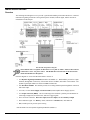
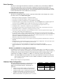
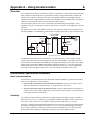
WavePort/V units integrate WaveBook/516 architecture. In addition, the V16 unit includes a WBK10Abased analog input module; and V24 units include two WBK10A-based analog input modules. The
architecture includes buffered input for all channels, individual instrumentation amp/channel, per-channel
programmable gain, and an anti-aliasing filter. The operational description is presented separately for both
the WAVEBOOK Module and the WBK10A-based module(s).
WAVEBOOK Module Operation
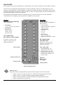
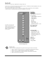
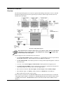
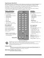
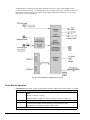
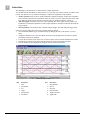
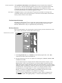
WavePort/V WAVEBOOK Modules include 8 signal-input channel BNCs (CH1 through CH8). Each of
these BNCs allows for two differential signals.
•
•
•
•
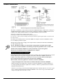
Both signals are buffered and applied to a differential amplifier.
The output of each differential amplifier is applied to a low pass filter.
The signals are switched (via multiplexer) to a programmable gain amplifier.
The amplified signals are level-shifted to the specified range. Note that unipolar offset (for sampling signals that
are always positive) and bipolar offset (for signals that may be positive or negative) are available.
• The signal is switched over to the A/D converter. The converter digitizes the signal to16 bits in 1 µs.
• The digitized value is conditioned to compensate for gain and offset errors.
• The conditioned signal is held in a FIFO data buffer until the PC reads the data. An internal processor checks
WAVEBOOK channel 1 to determine if a valid trigger event has occurred.
• The low-latency trigger is presented to a control and timing circuit for to start the acquisition after the trigger. The
TTL trigger is taken directly from the digital I/O port.
• At every sample time, WavePort’s Digital Signal Processor reads from the scan sequence table and accordingly
programs the Control and Timing Circuit for the next sample. In regard to the next sample, the Control and Timing
Circuit selects the input channel, PGA gain, level-shifter offset, and the A/D input source. It also conveys this
information to WBK10A-based modules (MODULE 1 and
MODULE 2) and precisely controls the A/D conversion timing.
• The Digital Signal Processor makes real-time sample corrections using calibration information that is stored in an
EEPROM.
• The digital I/O port is read and written by the processor to transfer bytes of digital data. The I/O port may be used
as a simple 8-bit input port or as a 32-address byte-wide I/O port.
• Acquisition data is sent from WAVEBOOK to the Notebook PC through a high-speed EPP
(Enhanced Parallel Port). The port makes use of a DB25 connector labeled “TO COMPUTER PARALLEL
PORT.”
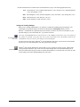
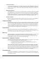
MODULE 1 and MODULE 2, Analog Expansion Modules
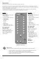
Each WBK10A-based expansion module provides 8 differential analog inputs. The modules are typically
equipped with a factory-installed programmable gain instrumentation amplifier (PGA). When WavePort/Vs
are ordered, the customer can specify that one of the following option cards be installed in place of the
standard PGA card: WBK11A, WBK12A, or WBK13A. Each of these options is discussed shortly.
Note 1: The standard WBK10A-based module comes with a pre-installed PGA card; however, WavePort
orders can specify that the module is to have a WBK11A, WBK12A, or WBK13A option card in
place of the PGA card.
Note 2: Refer to chapter 10 for specifications.
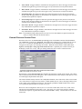
Hardware Setup Configuration
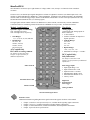
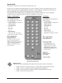
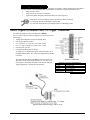
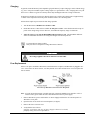
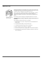
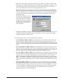
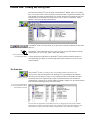
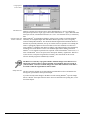
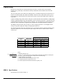
The analog input channel numbers are determined by the order
of connection among the WaveBook module and the
WBK10A-based modules (Module 1 and Module 2, as
applicable.)
•
•
•
•
4-8
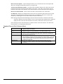
Channel 0 is the WaveBook module’s 8-bit digital I/O port.
Channels 1 through 8 are the WaveBook’s main channels.
Channels 9 through 16 (CH1-1 through CH1-8) are located on
the WBK10A-based Module 1 (not applicable to V8 units).
Channels 17-24 (CH2-1 through CH2-8) are located on the
WBK10A-based Module 2 (not applicable to V8 or V16 units).
Hardware and Operation Reference
09-29-00
WavePort
/V8, /V16, /V24
/V8, /V16, /V24
/V16 and /V24
Module
WaveBook
WaveBook
Module 1
/V24 only
Module 2
Channel #
0 (dig I/O)
CH1-8
CH1-1 to
CH1-8
CH2-1 to
CH2-8
WavePort User’s Manual