1
COMPACTVAR
BULLETIN 210D
VEC205D
GENERATOR EXCITATION:
AVR (AUTOMATIC VOLTAGE REGULAV OLTAGE R EGULATOR FOR
BRUSCHLESS ALTERNATOR OR WITH EXTERNAL AUXILIARY ROTARY EXCITER TO 50
AMPERE FIELD CURRENT OR STATIC EXCITER FOR COLLECTOR RING TYPE TO 1000
AMPERE FIELD CURRENT:
•
TOR ):
J4
N R
S
MINIMUM CONNECTION
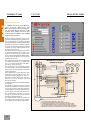
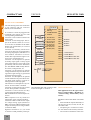
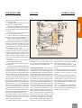
Simplified diagram
T
3 P HA SE S
PM G
E X CITA TIO N
T RA NS FO RM .
O R PM G
S E NS ING
T RA NS FO RM .
115 VCA
30 VA M IN .
P.T.s
S
T
A
B
R S T
A B
C
12
11
B2
B3
115 V
B4
5
B5
B6
7
3
F AN P.
S U PP LY
P O TENT .
500 O HM S
10
3
- P H AS E S - (O P TION ).
B UILD U P E NA BLE
FA IL
4
R EFER . O P T .
1
2
P O W E R - 115 /220 VCA/VCC
SEE TAG
Com .
N. O .
3
9
3
S EN S IN G P H A SE RT - O PT IO N .
MA
CC
PM G
B1
115 V
Fuses
C .T. IN /100
R S T
F U S ES
R
2 P HA SE S
PM G
+
VEC205EC
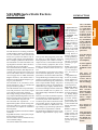
It allows keeping constant voltage at the
generator output and getting reactive current compensation in parallel operated
generators for KVAR sharing with another
machines or with the electrical supplier
network. The sharing of the reactive load
is made by Droop method based in the
machine Power Factor.
The Power Factor is digitally measured,
by means of signals from P.T. and C.T. in
the stator circuits or by an external transducer, like the GE Multilin SPM model.
In both cases the Droop rate can be adjusted from 0 to 5%.
The regulation mode can be selected by
an external command, to “Constant Voltage” or “Compound Voltage with Reactive Droop Compensation”.
The protections Loss of Signal, Generator Overvoltage, Generator Underspeed
and Exciter Overtemperature are active
in this application.
Some parameters can be adjusted in the
front panel: Proportional Gain (P - proportional action), Integrative Time (I Integrative action), Derivative time (D derivative action), Voltage scale and
Droop percentage.
Automatic Build Up with manual enabling
is available.
The mode of operation can be choused
Automatic or Manual. The manual operation can be used for a full range generator
voltage adjust, especially with auxiliary
power supply, for tests and characteristics measurement purpose or used in
emergency operation as a second channel
manual or manual follow up.
The Manual mode (or Drive mode) can
be used as a drive for an external regulator actuating at the setting range input.
B7
B8
6
EN AB LE
8
S IN GLE / P A RA LLEL
VEC 205E
(+)
(-)
G EN ER A TO R
(C O LE CTOR R ING
O R B R US HLES S )
N otes:
1: The C ircuit B reaker C B 2 and its conections
is not used in case off P M G - Perm anet M agnet G enerator.
2: The B uild U p E nable button is not used in case off use w ith PM G .
3: IF used w ith PM G w ith 2 Phases connect input T to gheter input R .
4: C o nnect Pow er Input (1 an d 2) to PM G if it’s vo ltage range is adequate.
5: A ll W ires to co nnector 3 (C om m om ) m ust be conn ecte d straight to it.
-