1
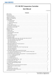
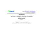
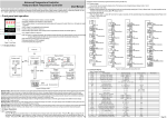
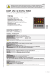
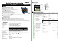
SESTOS
TM
Digital Temperature Controller
MANUAL
Nomenclature
Output
Alarm 1
Alarm 2
Manual
Setting key
:Move,Auto adjustment
:Down key
:Up key
:Present value
:Set value
Model: D1S
SESTOS
TM
TEMPERATURE
Features
PV
DIN(48X48mm) Temperature Controller
Support multi sensor input (K,S,Wre,T,E,J,B,N,CU50,PT100)
Wide control range -50 1300 (K sensor)
Indication and control accuracy 0.1 , high measurement
accuracy 0.2%FS
PID and ON/OFF control mode
Output and alarm format can be set by user
Built-in digital filter reduce interfere
Self calibration technology, keep stabilization
0.39" height LED, prevent dazzle, highly visible display
Switching power supply and low consumption
SV
OUT
D1S
Safety Precautions
M50
P
t
Ctl
Sn
Specification
Character :
Unit:
Range:
Contact output(D1S-2R): AC 250V 3A(Resistive load) NO/NC.
Alarm 1 AC250V 3A(Resistive load) NO/NC.
SSR(D1S-VR):
12V; Alarm 1 AC250V 3A(Resistive load) NO/NC.
Life expectancy:
Mechanical: 10,000,000 operations min. Electrical: 100,000 operations min.
Sampling period:
0.5 S
Indication accuracy:
0.2%FS 0.1 (under 1000 ); 1 (over 1000 )
Data storage:
10 years
Temperature compensating: 0-50
Cutout size:
45X45 mm
Mounting Method:
Flush mounting and screw terminals
Weight:
Approx.140g
Ambient temperature:
Operating: -10 55 (with no icing or condensation)
Storage: -25 65 (with no icing or condensation)
Ambient humidity:
35 85% RH
RUN
AT
RUN
SET
Function
Description
HIAL Absolute-value upper-limit
LoAL Absolute-value lower-limit
dHAL Upper limit(deviation)
dLAL Lower limit(deviation)
Hysteresis
dF
CtrL Control output
This product must be mounted on the panel, avoid electric shock.
When the power is turned on, is not connecting the terminal, avoid electric shock.
Ensure the product within the specification.
Never disassemble, repair or modify the product, if needed please contact agent or us
Do not use the product in locations subject to gases, dust, vibration, corrosive direct sunlight, water and
oil, strong EMI
The power supply and input circuit are isolated.
AC 100-240V 10% 50/60Hz 5VA
AC/DC 12-24V 10%
4VA
PV: 4 digital 9.9mm height, high light red LED
SV: 4 digital 8.0mm height, high light green LED
AL 2
Setting and function description
Thank you very much for selecting SESTOS products, Please read and understand
this MANUAL before using this unit.
Power and input:
Voltage(Ordering):
AL 1
SET
Integral
Differential
Hysteresis time
Control period
Input sensor
Decimal point position
dIP
dIL
dIH
SC
oP1
Sensor calibration
Output method
oPL
oPH
ALP
CF
Output lower limit
Output upper limit
Alarm function
System function
Addr
Baud
dl
run
----Input digital filter
Run mode
Loc
EP1
EP2
EP3
EP4
EP5
EP6
EP7
Ep8
input lower limit display
input upper limit display
-------------------
Range
Unit
-1999- +9999
1
-1999- +9999
1
0-9999
1
0-9999
1
0-200.0
0.1
0: ON/OFF; 3: PID;
2: Auto adjustment
0-9999
0.1
0-9999
0.01S/
1-9999
S
0-120
S
0: K
4: E
1: S
5: J
2: Wr
6: B
3: T
7: N
0-3
-1999- +9999
1 digital
-1999- +9999
1 digital
-199- +199
0.1
0: Time duty;
2: AL1 together with OUT
----0-31
2: Heater;
3: Cooler
0-20
0:Maunal;1:Automatic;
2:inhibit manual
Remarks
0: cancel
0=0.5S
20: CU50
21: PT100
PV=PV'+SC
See T1
Filter effect
Factory setting
9999
-1999
9999
9999
0.3
3
1000
500
120
4
0
1
0
1000
0
0
0
100
0
2
1
9600
0
2
40
none
none
none
none
none
none
none
none
Alarm function table (T1)
Upper limit output AL1
Upper limit alarm Al2
Lower limit output AL1
Lower limit alarm Al2
Upper limit(deviation) output Al2
Upper limit(deviation) output AL1
Lower limit(deviation) output AL1
Lower limit(deviation) output Al2
Note: Can set alarm in combination format, choice the requirement functions and sum of the value
setting in ALP.
Operation Procedures:
1/ Press SET key 2 second into the function mode, after return to the operation mode. If no any change
after 10 second automatic return.
2/ For temperature setting, press the UP or Down key change the value, after 10 second operate the new
setting.
3/ First operate the Auto adjustment, press AT key 2 second, SV display blink AT, finally into PID control
mode. Press the AT key 2 second to abandon Auto adjustment.
4/ If successful the first Auto adjustment, can not use AT key for Auto adjustment again. It need change
function setting Ctrl to 2 to operated again.
5/ Auto adjustment needs from few second to few hour.
Suggestions:
1/ If use SSR or SCR for control part, setting control period prefer 4 second or shorter.
2/ If use relay for control part, setting control period prefer 20 second or longer for extend the relay life.
Dimensions with Flush Mounting Adapter
Flush Mounting Adapter
Dimensions
Panel Cutouts
Min.60
Min.63
All units are in millimeters unless otherwise indicated.
Flush mounting adapter: YX-Y1 (Provided)
Terminal Arrangement
D1S-VR
1
D1S-2R
6
11
7
1
7
3
8
3
4
9
4
10
5
12
5
6
11
Output
Output
8
9
12
10
Precautions
Separate the input signal cables from the power line.
Short connecting wire from the sensor to the product is the best, if not please using shield cable.
Use and store the product within the ratings specified for temperature and humidity
Specifications and design subject to modifications without notice
SESTOS (H.K.) ELECTRONICS CO.
http://www.sestos-hk.com
E-mail:[email protected]