1
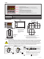
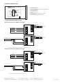
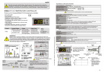
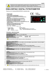
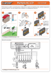
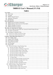
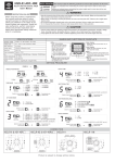
english
Read this document carefully before using this device. The guarantee will be expired by
damaging of the device if you don't attend to the directions in the user manual. Also we don't
accept any compensations for personal injury, material damage or capital disadvantages.
ENDA ETM442 DIGITAL TIMER
Thank you for choosing ENDA ETM442 digital timer.
* 48x48mm sized.
* 2x4 digits display.
* Easy to use by front panel keypad.
* Selectable 9 different time bases between 0-99.99s and 0-9999h.
* Selectable PNP or NPN sensor type.
* Selectable up/down counting direction for time.
* Adjustable Minimum On and Off times for pulses.
* Operation with or without memory for each output type.
* 9 different output types.
* Bottom display can be adjusted to show time unit or set value.
* Selectable functional reset.
* Parameter access protection on 3 levels.
* Easy connection by removable screw terminal.
* Having CE mark according to European Norms.
ETM442
OUT
PV
SV
SET
PRESET
ENDA
Supply Voltage
230V AC +%10 -%20
24V AC ±%10
RESET
DIGITAL TIMER
RoHS
conform
Order Code
ETM442
ETM442-24AC
TECHNICAL SPECIFICATIONS
ENVIRONMENTAL CONDITIONS
Ambient/storage temperature 0 ... +50°C/-25 ... +70°C (with no icing)
80% up to 31°C decreasing linearly 50% at 40°C.
Max. relative humidity
According to EN 60529
Front panel : IP60
Rated pollution degree
Rare panel : IP20
Height
Max. 2000m
Do not use the device in locations subject to corrosive and flammable gases.
up to date: 01022014, modification reserved and can be change any time previous notice !
ELECTRICAL CHARACTERISTICS
Supply
Power consumption
Wiring
Date retention
EMC
Safety requirements
230V AC +10% -20%, 50/60Hz or 24V AC ±10%, 50/60Hz
Max. 5VA
2.5mm² screw-terminal connections
EEPROM (Min. 10 years)
EN 61326-1: 1997, A1: 1998, A2: 2001 (Performance criterion B for the EMC standard)
EN 61010-1: 2001 (pollution degree 2, overvoltage category II)
INPUTS
START input
GATE input
RESET input
Input types can be adjusted as PNP or NPN in programming mode.
Minimum On and Off times for input pulses can be adjusted between 5 and 100ms.
For PNP input types, active level is 5 to 30V pulse,
For NPN input types, active level is 0 to 2V pulse.
OUTPUTS
Relay : 250V AC, 2A (for resistive load), NO+NC
Open collector output (S.S. OUT): Max. 30V DC, 100mA
12V DC, max. 50mA (without regulation)
Auxiliary power supply
Mechanical 30.000.000 operation; Electrical 300.000 operation
Life expectancy for relay
Note : Relay and S.S.OUT outputs are in synchronization . When OUT relay is energized S.S. OUT transistor goes into saturation.
Control output (OUT)
HOUSING
Housing type
Dimensions
Weight
Enclosure material
Suitable for flush-panel mounting according to DIN 43 700.
W48xH48xD87mm
Approx. 210g (after packing)
Self extinguishing plastics
While cleaning the device, solvents (thinner, benzine, acid etc.) or corrosive materials must not be used.
1./5
ETM442-E
TERMS
ETM442
OUT
(1) Time value during run mode.
Parameter value or mnemonic parameter code during programming mode.
(2) Set value or time unit during run mode.
Parameter value, unit or mnemonic parameter code during programming mode.
(3) Output LED.
PV
SV
(4) Increment key during run and programming modes.
Parameter selection key during programming mode.
(5) Parameter selection and reset key during programing mode.
Decrement key during run and programming mode.
(6) Used for selecting options or digits to be changed.
SET
RESET
PRESET
ENDA
DIGITAL TIMER
(7) Used for selecting run or programming modes or for adjusting the parameter.
( 1 ) PV display
( 2 ) SV display
4 digits, seven segment red LED
4 digits, seven segment yellow LED
Character height
PV display (1) :
SV display (2) :
One red LED
Micro switch
( 3 ) Output LED
( 4 ),( 5 ),( 6 ),( 7 ) Keypad
DIMENSIONS
7.1mm
7.1mm
Depth
2
Panel cut-out
87mm
51mm
1
+0.6
ETM442
45
mm
PV
mm
48mm
+0.6
SV
PRESET
ENDA
45
SET
RESET
DIGITAL TIMER
Connection
cables
60mm
54mm
OUT
For removing mounting clamps:
- Push up the flush-mounting
clamp in direction 1 as
shown in the figure above.
- Then, pull out the clamp in
direction 2.
Flush mounting
clamp
Note 1) While panel mounting, additional distance required for
connection cables should be considered.
2) Panel thickness should be maximum 10mm.
3) If there is no 80mm free space at back side of the device,
it would be difficult to remove it from the panel.
Panel
CONNECTION DIAGRAM
ENDA ETM442 is intended for installation in control panels. Make sure that the device is used only for intended
purpose. The shielding must be grounded on the instrument side. During an installation, all of the cables that are
connected to the device must be free of energy. The device must be protected against inadmissible humidity,
vibrations, severe soiling and make sure that the operation temperature is not exceeded. All input and output
lines that are not connected to the supply network must be laid out as shielded and twisted cables. These cables
should not be close to the power cables or components. The installation and electrical connections must be
carried on by a qualified staff and must be according to the relevant locally applicable regulations.
ENDA INDUSTRIAL ELECTRONICS
ETM442 DIGITAL TIMER
8
S.S. OUT
2
9
RESET IN
3
10
START IN
4
11
GATE IN
5
12
GND
6
+12V 30mA
7
SN: XXXXXXXXX
230V AC +10% -20%
50/60Hz 5VA
OUT
AC 250V 2A
RESISTIVE LOAD
ENDA INDUSTRIAL ELECTRONICS
NOTE :
ETM442-24 AC DIGITAL TIMER
SUPPLY:
8
S.S. OUT
2
9
RESET IN
3
10
START IN
4
11
GATE IN
5
12
GND
6
+12V 30mA
7
SN: XXXXXXXXX
24V AC 10 % -20%
50/60Hz 5VA
OUT
AC 250V 2A
RESISTIVE LOAD
184-253V AC 8
50/60Hz 5VA 9
Fuse
F 100 mA
250V AC
Faz
Nötr
Switch
230V AC Supply
Fuse should
be connected.
Cable size: 1,5mm²
Note : 1) Mains supply cords shall meet the requirements of IEC 60227
or IEC 60245.
2) In accordance with the safety regulations, the power supply
switch shall bring the identification of the relevant instrument
and it should be easily accessible by the operator.
Holding screw 0.4-0.5Nm
Equipment is protected throughout
by DOUBLE INSULATION.
2./5
ETM442-E
key is pressed while holding
PRESET
SET
RESET
RESET
RESET
SET
Set.
mEm.
RESET
1.000
SET
SET
1.000
key and use
PRESET
RESET
SET
keys.
PRESET
SET
Up
0.005
sec.
Time.
dir.
Puls
timE
MEm.
SEt
no
ConF.
1
nPn
SEnS.
tyPE
outP.
typE
99.99
Sec.
tImE
bA5E
yes
ConF.
3
0.020
sec.
9999
Sec.
DÝSP.
Bot.
RESET
oPtý.
dýsP.
ConF.
2
0.010
sec.
dn.
PnP
999.9
Sec.
1.010
and
SET
RESET
RESET
1.000
keys together.
key, the value of the selected parameter can be changed by
key. And then, press both
1.000
SET
SET
PARAMETER MODIFICATION DIAGRAM
keys. In order to reset all the digits, first press and hold
SET
PRESET
Device can be operated with memory or
without memory modes for 9 output types.
See NOTE 2 for modification.
key the value of the selected parameter is seen on the display. While holding
NOTE 2 To modify non-mumerical parameters, hold
Selected
numerical
parameter
parameter
There are 9 different output types.
Output types are at the next page.
See NOTE 2 for modification.
key, the
RESET
typE
Minimum On and Off times for the pulses of
the external inputs (RESET, START and GATE)
can be selected. This selection affects all 3 inputs.
See NOTE 2 for modification.
PRESET
using
RESET
OutP.
Counting direction can be selected as Up or dn.
See NOTE 2 for modification.
Sensor type can be selected as nPn or
PnP This selection affects all 3 inputs.
See NOTE 2 for modification.
There are 9 different time intervals.
They are
0-99.99s, 0-999.9s, 0-9999s
0-99.99min, 0-999.9min, 0-9999min
0-99.99h, 0-999.9h and 0-9999h.
Warning: Changing this parameter
affects the values of Ton ve Toff.
See NOTE 2 for modification.
NOTE 1 Holding
time
puls
Dir.
týmE.
TYPE
Sens.
bAsE
Time
RESET
oPtý.
PRESET
programming mode is enabled.
if
See NOTE 1 for adjusting the set value.
Ton or Toff
Bot.
DiSP.
bottom display shows time unit or one of the
set values (Ton or Toff).
Depending on the value of the
OutP.
PRG
29.8
200.0
Run mode
ýnPt.
SET
200.0
Toff
100.0
Ton
Sec.
Set
oPtý.
PRESET
BASE
29.8
DiSP.
INPT. oPTi.
OuTP. OPTi.
Bot.
ConF.
5
0.100
sec.
999.9
min.
ConF.
6
9999
min.
PRESET
ConF.
7
99.99
Hour
ConF.
8
999.9
Hour
by
bAsE
Time
3./5
ETM442-E
parameter, time unit also changes.
WARNING: As the selected time interval changes
ConF.
9
9999
Hour
PARAMETER TABLE
Bottom display value can be selected.
If BASE is selected, one of the time units
(Sec., Min. or Hour) is displayed.
If Set is selected, Ton or Toff value is
displayed.
See NOTE 2 for modification.
ConF.
4
0.050
sec.
99.99
min.
disP. oPTi.
SECU. oPTi.
no
def.
SEt
Prog.
yES
SECU.
SEt
def.
RESET
r.SEt
= Both RESET input and the
key can
RESET
be used for resetting.
2. for modification.
= Timer can be reset by the RESET input.
= Timer can not be reset.
= Timer can be reset by RESET key.
See NOT 2. for modification.
no
= All the modifications are saved.
Yes = Default values are set to parameters.
While leaving the programming mode,
both
See NOT
r.SEt
inP.t.
PAnE.
r.SEt
RESET no
Time.
= Menu is seen and programming is possible.
= No menu is seen.
= Menu is seen but can not be programmed.
See NOT 2. for modification.
Prog.
yES
Prog.
no
RESET nonE
SECU.
= Menu is seen and programming is possible.
= No menu is seen.
= Menu is seen but can not be programmed.
See NOT 2. for modification.
Prog.
no
Out.o.
dýs.o.
= Menu is seen and programming is possible.
= No menu is seen.
= Menu is seen but can not be programmed.
See NOT 2. for modification.
Prog.
yES
Prog.
no
RESET nonE
SECU.
ýnP.o.
PRESET
both
Access code for entering security option menu.
This parameter should be 1111.
See NOTE 2 for modification.
yes
r.SEt
inP.t.
Prog.
yES
Prog.
no
PAnE.
r.SEt
Prog.
yES
Prog.
yES
Prog.
no
Prog.
no
Set
RESET nonE
codE
SECU.
RESET
oPtý.
SECU.
no
nonE
diS.o.
SECU.
TimE.
r.SEt
nonE
nonE
1111
BASE
Out.o.
SECU.
InP.o.
SECU.
SECU.
codE
Bot.
DiSP.
OUTPUT TYPES
t: Partial time of TON or TOFF.
TON: Relay On time
: Indefinite time
TOFF: Relay Off time
Without memory
Power
With memory
While the device is energized,
If START is active, relay is energized after delay time
(TOFF).
Power
Config. 1
Start
Delay on energization
Reset
Start
Reset
Relay
Relay
t
t1
Power
t2
t
t
While the device is energized,
If START input is active, relay becomes Off and On
periodically during TOFF and TON times respectively.
At the end of each TON time START input is checked.
If it START is passive, timer stops and initial conditions
are returned. Otherwise, periodic operation continues.
Power
Config. 2
Cyclic timing
Single cycle
Start
Reset
Relay
Start
Reset
Relay
t
t
t
t1
Power
t2
t
t
While the device is energized,
With an impulse at the START input, relay becomes On
during TON time. Then, relay becomes Off.
Power
Start
Config. 3
Timing on impulse
(one shot)
Reset
Start
Reset
Relay
Relay
t
t1
Power
t1
t2
t2
With an impulse at the START input, relay becomes On.
However, timer do not counts while START is active.
When START becomes passive, relay becomes Off after
a time delay (TON).
Power
Start
Start
Config. 4
Timing after impulse
Reset
(delay off)
Relay
Reset
Relay
t
t
t
t1
Power
t2
t
t
While the device is energized,
If START input is active, relay becomes first Off and then On
periodically during TOFF and TON times respectively.
As soon as START becomes passive, timer stops and initial
conditions are returned.
Power
Config. 5
Cyclic timing
Start
Reset
Start
Reset
Relay
Relay
t
t
t1
Power
t2
t
t
t
While the device is energized,
If START input is active, first TON and then TOFF times are
passed periodically.
As soon as START becomes passive, timer stops and initial
conditions are returned.
Power
Config. 6
Cyclic timing
Start
Reset
Start
Reset
Relay
Relay
t
t
t1
Power
t2
t
t
t
While the device is energized,
If START input is active, relay becomes On
during TON time. Then, relay becomes Off.
Power
Start
Config. 7
Timing on energization
Reset
Start
Reset
Relay
Relay
TON
TON
t
TON
t1
t2
t
While the device is energized,
If START is active, relay is energized after delay time
(TOFF). If START becomes passive before TOFF time,
timer waits for another active signal at the START input
to complete the TOFF time.
Power
Power
Config. 8
Timing on energization
with memory
Start
Reset
Start
Reset
Relay
Relay
t1
t2
t1
t2
t1
t2
t1
Power
Power
Start
Start
Reset
Relay
t1
t2
t
t1
t2
t1
t2
Config. 9
Timing on energization
Reset
with memory
Relay
+reset by START input
after TOFF
t1
t2
t2
t1
t
t1
t2
t2
While the device is energized,
If START is active, relay is energized after delay time
(TOFF).
If START becomes passive before TOFF time,
timer waits for another active signal at the START input
to complete the TOFF time.
If START becomes passive after TOFF time, reset occurs.
Relay is de-energized and initial condition is returned.
NOTE: if Gate input becomes active, timer enters into wait mode. Timer waits at that condition until gate input becomes passive
4./5
ETM442-E
TERMINAL CONNECTIONS
ENDA INDUSTRIAL ELECTRONICS
Terminal description
ETM442 DIGITAL TIMER
8
S.S. OUT
2
9
RESET IN
3
10
START IN
4
11
GATE IN
5
12
2 : Solid state out (Max 30V 100mA, open collector NPN)
3 : Reset input (Max 30V)
4 : Start input (Max 30V)
5 : Gate input(Max 30V)
6 : GND
7 : +12V 30mA auxiliary supply output for sensors
8,9 : SUPPLY input
10,11,12 : Relay contacts (Max 2A 250V AC)
230V AC +10% -20%
50/60Hz 5VA
OUT
AC 250V 2A
RESISTIVE LOAD
GND 6
+12V 30mA 7
SN: XXXXXXXXX
TYPICAL SENSOR CONNECTIONS
Typical connections for PNP sensor type
8
Fuse
F 100 mA
250V AC Switch
230V AC Supply
2
9
Cable size: 1,5mm²
RESET
START
GATE
3
10
4
11
5
12
6
+ 12V
7
8
Fuse
F 100 mA
250V AC Switch
230V AC Supply
PNP PROXIMITY SWITCH
2
9
Cable size: 1,5mm²
OUT (active level is sensor supply voltage)
GND
3
10
4
11
5
12
6
+ 12V
7
NOTE: FOR PNP SENSOR TYPE ACTIVE LEVEL IS AUXILIARY POWER SUPPLY VOLTAGE.
Typical connections for NPN sensor type
8
Fuse
F 100 mA
250V AC Switch
230V AC Supply
2
9
Cable size: 1,5mm²
RESET
START
GATE
GND
3
10
4
11
5
12
6
7
8
Fuse
F 100 mA
250V AC Switch
230V AC Supply
NPN PROXIMITY SWITCH
2
GND
+ 12V
9
Cable size: 1,5mm²
OUT active level GND )
3
10
4
11
5
12
6
7
NOTE: FOR NPN SENSOR TYPE ACTIVE LEVEL IS GROUND (GND).
SURAN Industrieelektronik
Im Mitteldorf 26 / D-72160 Horb a.N
Tel.: +49 (0)7451 / 625 617
Fax: +49 (0)7451 / 625 0650
E-mail : [email protected]
Internet : www.suran-elektronik.de
5./5
ETM442-E