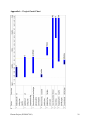
1
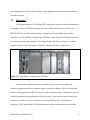
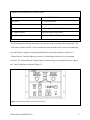
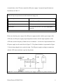
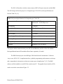
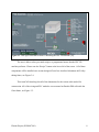
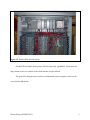
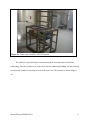
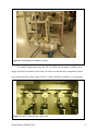
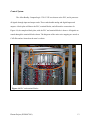
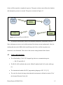
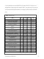
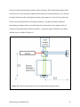
Digital PECVD Machine Design and Construction
ECE4007 Senior Design Project
Section L01, Plasma Project Team
Project Advisor, Dr. Keezer
William Edwards
Zlatan Ceric
David Ogden
Quan Tran
Timothy Gurtler
Submitted
December 16, 2010
i
Table of Contents
Executive Summary ......................................................................................................... iii
1. Introduction ..................................................................................................................1
1.1
1.2
Objective .............................................................................................................1
Motivation ...........................................................................................................2
2. Project Description and Goals ....................................................................................3
3. Technical Specification ................................................................................................4
4. Design Approach and Details ....................................................................................10
4.1
4.2
Design Approach ................................................................................................10
Codes and Standards ...........................................................................................15
5. Schedule, Tasks, and Milestones...............................................................................16
6. Results and Acceptance Testing ...............................................................................17
7. Marketing and Cost Analysis....................................................................................20
7.1
7.2
Marketing Analysis .............................................................................................20
Cost Analysis ......................................................................................................21
8. Conclusions and Future Work..................................................................................23
9. Reference ....................................................................................................................27
Appendix A .......................................................................................................................29
Plasma Project (ECE4007L01)
ii
Executive Summary
The Georgia Institute of Technology’s Nanotechnologies Research Center (NRC)
commissioned the design and construction of a digital plasma-enhanced chemical vapor
deposition (PECVD) machine that will be used for polymer deposition. The plasma chamber for
the new PECVD machine was removed from an old reactive-ion etching (RIE) machine. A PLC
controls the components, while a touch-screen interface acts as the human machine interface
(HMI). The HMI interface allows users to select key recipes with ease, thus reducing the need
for costly and time consuming training of personnel. The gas recipes control the thin film
deposition of each layer during the process. The Programmable Logic Controller (PLC) controls
and automates the three fundamentals sub systems of the PECVD including RF power supply,
mechanical pump, and mass flow regulators. There are three necessary set points for the PECVD
to function: the chamber vacuum pressure, an RF power, and gas flow rate. A mechanical pump
reduces the plasma chamber pressure to a specific set point, depending on the type of gas used.
The mass flow controllers then allow the gas to enter the chamber at a specified set point. Once
the pressure level is reestablished via the gate valve the gas is ionized by an RF voltage,
depositing the layer on a substrate. The digital PECVD machine is more efficient, easier to use,
and more reliable than its analog predecessor. The cost of materials for construction of the
PECVD machine was $35,000 and has a market value of approximately $250,000. The finished
product is a base model that allows for several future modifications. The addition of a heater
would allow for high temperature application while a turbo pump would lower the range of
vacuum level. Software modifications can be made directly on the HMI.
Plasma Project (ECE4007L01)
iii
1.
Introduction
The Plasma group has spent $35,000 in funding from the Georgia Institute of
Technology’s Nanotechnology Research Center (NRC) to construct and automate a PlasmaEnhanced Chemical Vapor Deposition (PECVD) machine. The new machine controls variables
such as RF power, vacuum level, and gas flow rate, using a programmable logic controller (PLC)
and touch-screen interface.
1.1
Objective
The team has recovered the components necessary to assemble and automate the digital
PECVD machine from the supplied Plasma-Therm 700 series RIE machine. The final product is
a stand-alone machine directed toward university micro and nanotechnology research facilities,
as well as semiconductor manufacture industries. The design utilized four different types of
gases and an externally mounted touch screen monitor for the user interface. The PLC was used
to control the three fundamental parameters of the PECVD machine including vacuum pressure,
gas flow rate, and RF power. The PLC program was coded in ladder programming language
using the RSLogix5000 software from Rockwell Automation. Ladder logic language is a means
of writing program in circuit blocks that can then be converted into machine code by the PLC
microprocessor.
The included human machine interface (HMI) consists of hardware and software allows
for user to interact with the PLC. The NRC staff has supplied recipes for semiconductor
fabrication that have been loaded into the HMI. Recipes are parameters of flow rate, RF power,
and vacuum pressure having the correct composition to ignite plasma from a gas. The GUI was
Plasma Project (ECE4007L01)
1
created using the FactoryTalk View software, which displays pre-determined recipes and usersdetermined recipes.
1.2
Motivation
The Georgia Institute of Technology NRC requested the group to assemble and automate
the machine. There are PECVD machines currently available on the market; however, new
PEVCD machine cost in the $250,000 range. Using the recovered chamber, the four flow
controllers, the Allen-Bradley CompactLogix L35E PLC, and a total cost of $35,000, the group
has constructed a functional machine. The CompactLogix L35E shown in Figure 1.2 utilized
modular cards for it input and output connections, allowing for future expansion [1].
Figure 1.2. Allen-Bradley CompactLogix L35E PLC.
Using modular components allows for simpler repair as the user can replace any
defective components unlike the complete control system in the Plasma-Therm 700 embedded
machine. The program for the PLC was stored in battery-backed memory, allowing the system to
function immediately after replacement of defective parts. Users can also keep a backup of the
programs on hard drives or any storage devices and upload to the PLC via an Ethernet
connection. The CompactLogix L35E microprocessor converts ladder logic code to machine
Plasma Project (ECE4007L01)
2
code, which operates at faster speeds [2]. The mounted touch screen monitor provides larger
color display and simpler user interface when compared to the old onboard control and screen of
the Plasma-Therm 700.
2.
Project Description and Goals
This project successfully converted an outdated plasma-therm RIE machine to a digital
PECVD machine. This was accomplished by replacing the outdated knobs and switches with a
PLC based controls system and HMI. The intended RF power supply was replaced due to
malfunctions. The new RF power supply required water cooling and new wiring. The device has
the following properties:
PLC:
•
Mounted on centralized din rail
•
Controls power, vacuum, and gas flow sub-systems
•
Intuitive modification with ladder logic programming
Functionality:
•
Provides standard recipes for users (created by NRC staff)
•
Allows users to create, modify, and execute deposition processes
•
Displays current deposition recipe status
•
Allows touch-screen interface
•
Incorporated pressure sensor for safety precaution
•
Ignites and controls plasma with RF power supply
•
Provides continuous feedback of set points through HMI
•
Controls mixing of gases with mass flow controllers
•
Market Value $250,000
•
Cost of parts $35,000.00
Plasma Project (ECE4007L01)
3
3.
Technical Specifications
The digitally automated PECVD machine is composed of the following main
components:
•
Plasma chamber
•
Four mass flow controllers for different gases
•
ATX tuner for RF matching network
•
RF power supply
•
PLC
•
HMI on a ASUS 1.6 GHz touch-screen PC
•
Pressure sensor
•
Custom built frame to hold all of these components
The PECVD machine can utilize four different gases: Ar, O2, CHF3, and C4F8. The flow rate of
each gas is controlled by a Brooks Model 5850E Mass Flow Controller, as seen in Table 3.1. The
mass flow controller (MFC) is regulated by the PLC, which is able to send and receive data from
the MFC. This ensures that the gas flow rate is regulated and consistent.
The RF power supply is controlled by an ATX tuner, which is a “RF matching network
designed to convert the complex impedance of plasma at 13.56 MHz to 50 Ω resistive” [9]. The
physical specifications for this device are in Table 3.2.
Plasma Project (ECE4007L01)
4
Table 3.2. Specifications for ATX-600 Tuner
Power Capacity
600 W, 1250 W, 2500 W
Frequency
13.56 MHz nominal
Impedance Range
5 ohms to 2000 ohms
RF Input Connector
600 W: Type N, 1250/2500 W: Type: HN
RF Output Connect
Universal output kit provided
Input Power
115 V ac ±10% or 220 V ac ±10%
This matching network helps maximize power transfer while restricting reflected powered. The
ATX tuner specified in Table 3.3 has an automatic mode that allows the device to automatically
tune the RF power supply, ensuring that stabilization occurs and a plasmid is achieved. A
“Plasma Present” indicator light gives the user a visual display that the device is operating
correctly. The “Plasma Present” indictor light is located midway on the panel and to the right of
the “Tuned” indicator as shown in Figure 3.1.
Figure 3.1. Front panel display of ATX-600 tuner [9].
Plasma Project (ECE4007L01)
5
As stated above, the ATX tuner controls the RF power supply. Its physical specifications are
listed below in Table 3.3
Table 3.3. Physical Specifications for RFX-600 Power Supply [10]
Power Output
600 W max into a 50 ohm load
Frequency
13.56 MHz ± 0.005%
Output Impedance
50 ohms
Input Power
115 V ac ±10% or 230 V ac ±10% single phase,
50/60 Hz
Please note that the power output of the RF power supply matches with the power input of the
ATX tuner; the RF power supply output impedance matches with the input impedance of the
ATX tuner; and the frequency of both devices are identical. A circuit level representation of the
RF power supply can be seen below in Figure 3.2. The plasma chamber is represented in Figure
3.2 by the dome shaped device on the far right. The RF power supply working in conjunction
with the ATX tuner transforms a gas into the plasma.
Figure 3.2. Circuit representation of the RF power supply connected to a plasma chamber [10].
Plasma Project (ECE4007L01)
6
The PLC will interface with the various sensors, MFCs, RF power network, and the HMI.
The PLC being used for this project is a CompactLogix 1769-L35E, and its specifications are
listed in Table 3.4 [11].
Table 3.4. System Specifications for CompactLogix 1769-L35E
Communication Ports
RS-232 – 19200Kbytes/sec
EtherNet/IP – 10/100 Mbytes/sec
User Memory
1.5 Mbytes
Nonvolatile Memory
1784-CF64 CompactFlash
Max I/O Modules
30 I/O Modules
Max I/O Bank
3 I/O banks
Power Supply Distance Rating
4 (logic must be 4 slots from power supply)
Operating Temperature
0 - 60°C
Storage Temperature
-40° - 85°C
Vibration
Operating: 5G @ 10-500 Hz
This project utilized communication ports, RS-232 and EtherNet, and five of the I/O modules.
Having additional unused I/O modules allows future expansion, if needed.
The HMI for this project is the RSLogix 5000 from Rockwell Automation. It features
“easy-to-use, IEC61131-3 compliant interface, symbolic programming with structures and arrays
and a comprehensive instruction set that serves many types of applications” [12]. The HMI
software will be installed on an ASUS Eee touch-screen PC. The graphical user interface (GUI)
can be seen in the screen shot in Figure 3.3.
Plasma Project (ECE4007L01)
7
Figure 3.3. RSLogix 5000 HMI software controlling the PECVD machine [10].
The user is able to select pre-made recipes, or programmed states, that the PECVD
machine performs. Please note the “Recipe” button at the lower left of the screen. All of these
components will be installed on a custom designed Gator Jaw Anodized Aluminum 6063 alloytubing frame, see Figure 3.4.
This AutoCAD drawling lists all of the dimensions for the various rails needed for
construction. All of the wiring and PLC modules were mounted on Panduit DIN rail inside the
Gator frame, see Figure 3.5.
Plasma Project (ECE4007L01)
8
Figure 3.5. Panduit DIN rail with wiring.
Panduit DIN rail makes wiring clean, efficient, and easily expandable. Please note the
large amount of wires in relation to the small amount of space utilized.
The goal of the designers was to achieve and maintain certain set points, which can be
viewed in the table below.
Plasma Project (ECE4007L01)
9
Table 3.5. Performance Specifications
Controlled Parameter
Desired Setpoint
Actual Reading
Vacuum Level
100 mTorr
Within 10% of setpoint
RF Power Output
100 or 150 W
Within 5% of setpoint with
< 5% reflected power
Gas Flow Rate
25 to 35 sccm
Within 1% of setpoint
Maintaining these setpoints allows the machine to ignite plasma for the process of
deposition. If any of the readings above deviate from their setpoint, the PLC program
compensates to restore the machine to the user’s input specifications. The reader should note
that maintaining these setpoints requires constant adjustment in the PLC program. If a parameter
cannot be held, then the program will terminate prematurely. This allows for a consistent recipe
to be achieved.
4.
Design Approach and Details
4.1
Design Approach
Physical Components
The PECVD was built as a single entity inside a chassis that acted as the stand for the
machine. The chassis is a Gator Jaw Anodized Aluminum 6063 alloy-tubing stand shown in
Figure 4.1. It will contain all of the hardware. The stand was fabricated to meet the needs of
housing each individual component. This type of material allowed for manipulations of the
chassis if components were replaced or added.
Plasma Project (ECE4007L01)
10
Figure 4.1. Frame used to build the PECVD machine.
The chamber was purchased pre-owned and required corrosion removal and minor
refurbishing. Once the chamber was set into the stand, the additional plumbing was then attached
to connect the chamber to the pump as well as the vent valve. This connect is shown in figure
4.2.
Plasma Project (ECE4007L01)
11
Figure 4.2. Plumbing from chamber to pump.
The smaller components such as the PLC, the MFCs, the pneumatics, and the power
supply could not be mounted to the chassis. In order to accomidate these components, plates
were custom ordered to attach chasis. Figure 4.3 shows the MFCs attached to a custom plate.
Figure 4.3. MFCs mounted onto a back plate.
Plasma Project (ECE4007L01)
12
Control System
The Allen-Bradley CompactLogix 1769- L35E was chosen as the PLC, and it processes
all signals through input and output cards. These cards handle analog and digital inputs and
outputs. A back plate will house the PLC, terminal blocks, and all interface connections. In
Figure 4.4, the completed back plate, with the PLC and terminal blocks is shown. All signals are
routed through the terminal blocks shown. The diagrams of the entire wire mapping are stored as
CAD files and are located on the team’s website.
Figure 4.4. PLC and terminal blocks.
Plasma Project (ECE4007L01)
13
A PLC programming language called ladder logic was used to control the PLC and
process the information [1]. This allowed for autonomous control of the all components to
maintain a list of user defined set points. The top-down structure of ladder logic programming
insures that the next process does not start until the set point of the previous task is achieved. The
PLC makes it possible for the PECVD to reach the set points and maintain all of the values
within a given variance. This ensures that the correct pressures, gas ratio, and power are
maintained throughout the duration of the cycle. A previous projects code was used as a template
for our design.[11] A touch screen HMI allows users to select and start the process as well as
select the combination of gases to use. The main display of the HMI was shown in Figure 3.3.
Here a mock up the system is displayed the shows in real time what is happening on the
machine. The set points as well as the actual values are displayed are also displayed.
Plasma Generation & Film Deposition
The machine can support and control the flow of four gases: O2, Ar, CHF3 and C4F8. A
predefined recipe determines how much of each gas is required for the process. MFCs inject the
gas into the chamber. A throttling valve controls the density of the gas in the chamber. The RF
power supply and a matching network are required to generate a high enough current to ignite
and maintain the plasma.
A mechanical roughing pump will bring the pressure in the chamber close to 100
millitorr. Once the pressure is achieved, gases are injected into the chamber. The PLC then
stabilizes the gas ratio. Next, the RF Power is applied to generate a cloud of plasma that is
capable of depositing a layer onto the silicon wafer. Based on the desired film, a defined amount
Plasma Project (ECE4007L01)
14
of time will be required to complete the process. The gases are then removed from the chamber
and atmospheric pressure is restored. The process is shown in Figure 4.5.
Mechanical
Pump
Activated
Film Deposited on
Wafer
Chamber
Pressure
Achieved
RF Power
Applied
MFCs Inject
Gas
Desired Gas
Ratio Present in
Chamber
Figure 4.5. Process Flow for PECVD
The design of the machine calls for a mechanical pump that is controlled by the PLC.
Since with pump was never received this portion of the design was not implemented. Also, the
trending function on the HMI, which would keep track of how well the set points were
monitored, is not functional. This is due to the extreme coding demand of this feature.
4.2
Codes and Standards
•
The Allen-Bradley 1769-L35E CompactLogix has two communication ports:
o RS-232 and a RJ-45.
•
The RJ-45 will be utilized and uses the 10BaseT standard with Cat5e as the cable type
[1].
•
The international standard for PLC programming language is IEC 1131 [13].
•
The code for electrical wiring in the industrial environment is defined in Article 670 of
the National Electrical Code [14].
Plasma Project (ECE4007L01)
15
•
5.
All other components are hardware and do not have associated standards.
Schedule, Tasks, and Milestones
The team was composed of two sub-sections: software and hardware. The software team
was responsible for the programming of the PLC and HMI, while the hardware team edited the
wiring schematics and installed electrical components. Table 5.1 shows the task, resource names
and timeline of each major task. The start date of the project is August 15th and the end date is
December 15th. These tasks may also be compared to the original Gantt chart located in appendix
A. The removal of existing controls systems was done promptly so that construction of the new
system was not be hindered. Most of the programming and testing occurred once the system was
entirely assembled.
• 5.1. Scheduled Tasks
Table
Task Name
Familiarization w/ existing system
Identification of existing component and wiring
Order replacement/ new parts for system
integration
Removal of existing controls system
Corrosion Removal
Installation of new control system
System Documentation
Programming of PLC and HMI
Debugging System
Writing Final Report
Plasma Project (ECE4007L01)
Resource Names
All
All
Start
Date End Date
8/15
8/29
8/15
9/19
Jason Harrington
Quan, Zlatan
Will, Tim, Zlatan
Tim, Zlatan
Will, David
Quan, Tim
All
All
8/22
8/15
9/5
9/26
8/29
11/12
12/1
12/10
9/19
8/22
9/12
10/3
11/28
11/28
12/7
12/15
16
6.
Results and Acceptance Testing
Many of the major components of the machine could not be tested before they were
installed. This required us to leave adequate time to test and replace components that were not
functional. Since the components are all controlled by the PLC, it was necessary for the code to
be completed as well before the testing phase began.
Once the fabrication was complete, it was important to insure that all wires were routed
to the proper location before power was applied to the machine. In order to test the connections,
continuity tests were performed on each wire form the PLC to the respected terminal blocks, and
when possible, from the terminal blocks to the specified destination. This test found errors that
could be corrected before any permanent damage occurred.
Testing each component of the machine individually was the next step of the testing process.
With the PLC software, we were able to force outputs and insure the component responded properly.
This strategy tested functionality of the MFCs, the gate valve, the throttle valve, the pneumatic
controller, and the RF power supply. After the components were activated the feedback was
monitored to insure that it matched the expected values based on the outputs that were forced. The
PLC was programmed to maintain certain ranges around the defined set points, which are listed in
Table 6.1.
Plasma Project (ECE4007L01)
17
Table 6.1. Acceptance Testing
Controlled Parameter
Desired Setpoint
Acceptable Range
Vacuum Level
100 mTorr
Within 10% of setpoint
RF Power Output
100 or 150 W
Within 5% of setpoint with
< 5% reflected power
Gas Flow Rate
25 to 35 sccm
Within 1% of setpoint
Once every individual component was working properly, the final step in the testing
process was to insure that the code would automate the entire process. Also, the machine was
required to accept user input of recipes to control how the deposition. The process of testing the
software was to input the set points via a recipe and start the process. The set points were
monitored to ensure they stayed within the tolerance range. The HMI displayed the set points as
well as the actual value to show that the machine was working properly; this is shown in Figure
6.1. The glowing plasma inside the chamber ended the testing process.
Figure 6.1. HMI set point monitoring.
Plasma Project (ECE4007L01)
18
The demonstration showed that the machine can be operated solely through the use of the
HMI. A stored recipe was recalled and with a single touch the entire process was initiated.
During the process, a mock up of the system showed exactly what was taking place. The set
point and feedback were displayed at all times. The physical glowing of the plasma through the
viewing window on the chamber proved that the HMI data was accurate and our process yielded
stable plasma. This plasma is shown in Figure 6.2.
Figure 6.2. Chamber with a successful Plasma ignition.
We proposed that we would have a feature call trending, which would keep a record of
all feedback through out the process. This would allow for monitoring of how much values
deviated from the set points and show when in the process the deviations occurred. We were not
Plasma Project (ECE4007L01)
19
able to implement this feature. We did not receive the mechanical pump for the project. This
required us to use a different model pump that did not allow for remote control or pressure
monitoring at the pump.
7.
Marketing and Cost Analysis
7.1
Marketing Analysis
PECVD units are custom tailored to each client’s needs and hence reflect the
requirements of the particular user. The types of gases used to generate the transport plasma, the
copious organic gases employed in the chamber, and RF power levels are all bespoke to the
customers need. The primary target clientele are research institutions along with semiconductor
and microelectronic manufacturing companies. More generally, the client spectrum consists of
those organizations wishing to deposit substrate layers with a large degree of uniformity and high
rate of speed. The ability to deposit controlled layers of poly silicon makes PECVD an
outstanding tool for companies working with solar cells and silicon based renewable energy.
This PECVD model features a touch-screen HMI, ideal for environments requiring ease
of use and a small operational learning curve. The HMI interface allows users to select key
recipes with great ease, thus cutting the need for costly and time consuming training of
personnel. Company technicians can readily select a recipe from our pre programmed menus,
effectively controlling the deposited substrate composition and thickness with turnkey alacrity.
The user centric approach of our HMI display endows this product with a multitude of
advantages over its analog controlled counterparts often found in today’s research and
manufacturing institutions.
Plasma Project (ECE4007L01)
20
Apart from uniformity, user interaction, and substrate choice versatility, this PECVD
employs RF generated plasma to facilitate reaction between user specified gases within the
chamber. RF generated plasma dictates relatively low operational temperatures, particularly on
the order of 300oC or more less that regular Chemical Vapor Deposition instruments. This
operating temperature range is particularly attractive to companies working with Silicon
substrate formation technology. The ability to abstract away the function of heating elements
makes this system highly amicable to the production of photonic crystal waveguides [15]. At the
higher temperatures encountered in CVD, many process driven defects can form in the deposited
layers, thus lowering yield and consequently process efficiency.
When properly equipped with a magnetic field module, further stimulation of the plasma
chamber at an electron cyclotron resonance enables several prospects in ion-implantation and
varied doping structures. This feature is of interest to companies working with GaAs, GaN, and
other III-V optoelectronic or high frequency microwave materials. The ability to locally
modulate temperature driven defects further opens the possibility of depositing novel material
thin films for energy research applications.
7.2
Cost Analysis
A comprehensive cost analysis of the PECVD system includes not only parts and labor,
but also associated design and testing cost. After carefully itemized review of required materials,
the total part cost was determined to be $34,275.98. Considering an annual salary for an ECE
graduate to be $77,700.00, a total of 400 man hours, 5 design and implementation team
members, the total labor cost comes to $104,711.54. This cost consists of labor, design, reports,
meetings, lectures, and final product testing and standards assessment. Unadjusted for inflation
Plasma Project (ECE4007L01)
21
or rise in manufacturer costs, the total PECVD cost reaches $138,987.52. At this level, it is
anticipated that a sizable margin can be obtained. Table 7.1 shows that nearly 50% of the total
cost is associated with the plasma chamber, power supply, mass flow controller, and throttle
valve.
Table 7.1. Itemized Cost
Item
Qty
Salvaged Plasma Chamber
10 Amp-3 pole circuit breaker
contactor for pump/chiller
overload for pump/chiller
enclosure for contactors
pushbuttons for contactor box - 3
position
pushbuttons for contactor box - 2
position
Eee PC Touch screen
Touch screen Swing Arm
AutoCAD 2010 Software
RF Power Supply + Warranty
Rockwell Student Software Package
end cap right for compactlogix system
relay - spst 24vdc coil
terminal block
terminal block jumpers
terminal block anchor
+/-15VDC Supply
24vdc power supply
single pole circuit breaker
3 pole circuit breaker
System Frame + Parts
120V power supply
Pressure sensors
Vacuum Tubing Parts
Mass Flow Controller
Throttle Valve
1
1
2
2
1
$2,500.00
$122.00
$170.00
$54.20
$388.30
1.00
1.12
1.12
1.12
1.12
$2,500.00
$163.97
$456.96
$145.69
$521.88
1
$37.10
1.12
$49.86
1
1
1
1
1
1
1
13
120
3
5
1
1
1
1
1
1
1
1
4
1
$37.10
$500.00
$100.00
$3,995.00
$4,950.00
$100.00
$31
$16.40
$0.98
$3.78
$1.77
$136.86
$119.09
$33.20
$122.00
$1,600.00
$428.00
$37.10
$506.70
$1,500.00
3,600.00
1.12
1.12
1.12
1.12
1.12
1.12
1.12
1.12
1.12
1.12
1.12
1.12
1.12
1.12
1.12
1.12
1.12
1.12
1.12
1.12
1.12
$49.86
$672.00
$134.40
$5,369.28
$6,652.80
$134.40
$41.66
$286.54
$158.05
$15.24
$11.89
$183.94
$160.06
$44.62
$163.97
$2,150.40
$575.23
$49.86
$681.00
$8,064.00
$4,838.40
$34,275.98
Plasma Project (ECE4007L01)
Cost/unit Inflation
Total
22
8.
Conclusions and Future Work
As a final design and an operationally working prototype, our PECVD unit functions with
few suggested modifications. The control system is in perfect performance. After having run
through several test scenarios, performance of the control system is per specification and does
not fail at any correctly delivered set point. The wiring binding is per engineering order and does
not exhibit entangling. After ignition, the plasma glow appears to be uniform when viewed by
human eye. Though functionality and performance exhibit a standard set forth in the proposal,
the system does have several faults. We strongly believe that these are a result of hasty last
minute decisions and half hazard relay remapping.
As the project deadline neared, the machine construction accelerated. Parts were finally
coming in on time, a major modulator of the construction plans and Gant chart reformulation.
When the main problems with the pneumatic solenoid were resolved, we believed the system to
be fully operational. As we proceeded to ignite our first plasma, our design team discovered that
the power supply and matching network were not operational. Frustrated by the approaching
deadline and the apparent inability to obtain a new power supply, we salvaged an old power
supply from a reactive ion etch machine available to us. Since the relay mappings on that
machine were virtually the same, we proceeded to wire the power supply exactly as is on the RIE
machine from which it was obtained. We strongly conjecture that the reflected power was
mapped to an improper relay. The basis for this conjecture is the performance of the HMI upon
final testing. While noticing the power supply indicators reading a reflected power of 5 W, we
found the HMI indicator display outputting 0 W. Though a perfect match is possible, this usually
tends to be a transient phenomenon. From our analysis we conclude that the reflected power
output from the matching network was improperly mapped, and as a consequence, the software
Plasma Project (ECE4007L01)
23
reading from the controller pulled a value which was low for all time. Though critical to the
future trending program, this error will be readily fixed. This augmentation is performed by
mapping the output of the matching network’s reflected power to the correct relay port
representing input to the controller.
Apart from the small port map issue involving the reflected power, we strongly dislike
the performance of our pump system. During testing, several issues were noticed with the age of
the pump and its ability to maintain pressure. As a result, an optimized design would embody a
new pump, preferable one with a warranty. Apart from this pneumatic consideration, one might
also desire to replace the power supply with a new model.
Though many possibilities for upgrading the machine exist, we choose to focus on a
possible diagnostic system. The current design occupies only about 60% of its contained volume,
thus endowing it with ample room to add additional functionality. Examples of additional
expansions include a magnetic field module for electron cyclotron heating (ECH), internal film
thickness interferometry, and replacement of the original heating coils removed from the
salvaged plasma chamber. Though these expansions are highly attractive, we choose to focus on
a density diagnostic which would easily incorporate into our current system. The notion of an
ancillary measurement of plasma density would be a natural evolution of the current design.
The current system is capable of inferring plasma density solely from the pressure, gas flow rate,
and reflected power parameters. Many studies have been performed on the effect of plasma
electron density deposition rates and substrate uniformity. Apart from acting as an effective
transport mechanism, effective electron density drives total power dissipation and heating.
Control over localized heating is an important consideration in ECH systems, further urging the
Plasma Project (ECE4007L01)
24
need for ancillary determination of plasma electron densities. When depositing substrate films,
researchers have noticed a plasma inducted defect density in the deposited layers [16]. Directly
correlated with the weakly ionized plasma density, this parameter is critical to the quality and
effective electrical performance of deposited substrates. A proposed ancillary method of
determining the plasma density is an interferometric measurement of the complex index of
refraction of the bulk plasma within the chamber. A proposed design, amicable to the current
machine setup is outlined in Figure 8.1.
Fir
Figure 8.1. Proposed interferometer for measuring chamber plasma density.
Plasma Project (ECE4007L01)
25
In this basic interferometric setup, a laser beam is split into two equal power beams by a beam
splitter. One beam is passed through the plasma chamber, while plasma is ignited. The other is
passed through free space and reflected back. The two beams are then recombined and an
interference pattern is formed exhibiting fringes whose intensity and spacing can directly be
correlated with the index of refraction of the plasma. Provided that the length of the two paths is
an invariant, a highly accurate measurement of the index of refraction can be made. The last
connection occurs in the direct functionality of the index on the plasma oscillation frequency,
which is in turn a direct consequence of the plasma electron density. The index of refraction of
the plasma changes the effective optical path in one arm of the interferometer, hence enabling
this measurement.
The data from the interferometry would be used as an additional measurement of plasma
density. They could easily be incorporated into the HMI and trending features planned for the
PECVD, once fully operational. Enabling this feature would require the addition of a special
section of the control program. In effect, this feature would expand the current plasma density
rung on the PLC ladder logic program. In essence, the original measurements would form a
rough target set point which would then be fine tuned with secondary feedback from the
interferometer extracted measurements. As a result, we strongly believe that this method would
achieve optimal control over plasma density and further refine uniformity of deposited layers.
Plasma Project (ECE4007L01)
26
9.
References
[1]
Allen-Bradley 1769-L35E CompactLogix System User Manual, Rockwell Automation,
Milwaukee, WI, 2003.
[2]
D. Du, X. Xu, and K. Yamazaki, “A Study on the Generation of Silicon-based Hardware
Plc by Means of the Direct Conversion of the Ladder Diagram to Circuit Design
Language,” International Journal of Advanced Manufacturing Technology, vol. 49, pp.
615-626, Jul. 2010.
[3]
M. Zverev, D. Peregudov, I. Sedova, S. Sorokin, S. Ivanov, and P. Kop’ev, “Lowthreshold electron-beam-pumped green quantum-well heterostructure semiconductor
lasers,” Quantum Electronics. vol. 34, pp. 909, Nov. 2004.
[4]
S. Han, M. Ceiler, S. Bidstrup, P. Kohl, and G. May. (2004, Jun.) Modeling the
Properties of PECVD Silicon Dioxide Films Using Optimized Back-Propagation Neutral
Networks. IEEE Transaction on Components, Packaging, and Manufacturing
Technology. [Online], 17(2). Available:
http://www.chbe.gatech.edu/kohl/Publication%20Articles/39Modeling%20the%20Properties%20of%20PECVD%20Silicon%20Dioxide%20Films%2
0U.pdf. [Accessed Sept. 20, 2010].
[5]
Plasma-Therm Inc 700 Series User Manual – Books 1 & 2, Plasma-Therm Inc, St.
Petersburg, FL, 1990.
[6]
“RF Gen Equipment,” Bid-Service LLC. [Online]. Available:
http://www.bidservice.com/Browses/SearchEngine_Browse.asp?keywords=%20RF%20
Plasma Project (ECE4007L01)
27
Gen&source=GooglePPC_Semi_General&gclid=CIPa25HG9aMCFQgQswodBAMl3A.
[Accessed Sept. 21, 2010].
[7]
GFC Mass Flow Controller Manual, Aalborg, Orangeburg, NY, 2006.
[8]
Brooks Instrument, “Brooks Model 5850E Mass Flow Controller,” DS-TMF-5850-MFCeng datasheet, Oct. 2008.
[9]
Advanced Energy ATX-600 Tuner User Manual, Advanced Energy Industries, INC., Fort
Collins, CO, 1994.
[10]
Advanced Energy RFX-600 Generator User Manual, Advanced Energy Industries, INC.,
Fort Collins, CO, 1991.
[11]
E. Ellis, N. Lourenco, R. Mainampati, Z. Costello, and A. Kardomates, “RIE Control
Upgrade for the Georgia Tech Nanotechnology Research Center,” Georgia Institute of
Technology, Atlanta, GA, 16 Sept. 2009.
[12]
Rockwell Automation, RSLogix 5000. [CD-ROM]. Milwaukee, WI, 2003.
[13] Rockwell Automation, “What is IEC 1131?”, Rockwell Automation, 2008. [Online].
Available: http://www.software.rockwell.com/corporate/reference/Iec1131/ [Accessed:
Sept. 21, 2010].
[14]
National Fire Protection Agency, NFPA 70: National Electrical Code, 2011.
[15]
S. Saini, C. Hong, N. Pfaff, L. Kimerling, and J. Michel, “Partial confinement photonic
crystal waveguides,” Applied Physics Letters, vol. 93, no. 26, Dec. 2009.
[16]
S. Saini, C. Hong, N. Pfaff, L. Kimerling, and J. Michel, “The Observation of Plasma
Induced Defect Desity at SiH Interface,” Journal of Non Crystalline Solids, 23, Jan. 1996.
Plasma Project (ECE4007L01)
28
AppendixA – Project Gantt Chart
Plasma Project (ECE4007L01)
29