1
!"
#$$ "%!%!&
!'(&
)'"*+"*!*!
!!*,-!,*!*.*"*'!
Abstract
A 169 MHz and 868 MHz Wireless M-Bus Based
Water and Electricity Metering System
Evangelos Kaloudiotis
Teknisk- naturvetenskaplig fakultet
UTH-enheten
Besöksadress:
Ångströmlaboratoriet
Lägerhyddsvägen 1
Hus 4, Plan 0
Postadress:
Box 536
751 21 Uppsala
In this master thesis we study and implement the wireless M-Bus protocol (the
wireless variable of standard M-Bus). We acquired measurements from an electricity
and water meter over wM-Bus. Specifically for the electricity meter, a ZigBee/wM-Bus
gateway was implemented. The implementation includes two sub- modes of wM-BUS,
S1m and N1b for both meters. S1m-mode functions in the 868 MHz frequency band
whereas N1b mode functions in the 169 MHz band. The measurements were
reported over serial communication to a BeagleBone or a PC for further exploitation.
Range test were performed for the 169 MHz frequency band. AES-128 CTR
encryption was also applied to the packets exchanged.
Telefon:
018 – 471 30 03
Telefax:
018 – 471 30 00
Hemsida:
http://www.teknat.uu.se/student
Handledare: Stylianos Koutroubinas
Ämnesgranskare: Leif Gustafsson
Examinator: Wang Yi
IT 15047
Tryckt av: Reprocentralen ITC
Acknowledgements First and foremost, I would like to thank my family and my girlfriend for their overall support during my studies in Uppsala but also the conducting of the thesis in Patras, Greece. I would also like to thank Leif Gustafsson, the reviewer of this thesis and my supervisor and CEO of MEAZON S.A, Stelios Koutroubinas. I would also like to thank all my colleagues in MEAZON S.A for their support and valuable advice and especially Nikos Koutsioumaris. This thesis is dedicated to the memory of Kostas Efstathiou, my mentor, my teacher, my professor. 24/5/2015 Patras, Greece Kaloudiotis Evangelos 4 Table of Contents Abstract ............................................................................................................................................ 3 1 Introduction ............................................................................................................................. 11 1.1 Background ...................................................................................................................... 11 1.2 The M-‐Bus ........................................................................................................................ 11 1.3 Problem Description ........................................................................................................ 14 1.4 Aim ................................................................................................................................... 15 1.5 Scope ................................................................................................................................ 15 1.6 Our involvement in MEAZON S.A ..................................................................................... 15 2 The Wireless M-‐Bus ................................................................................................................. 19 2.1 Introduction ..................................................................................................................... 19 2.2 The WMBUS modes and sub-‐modes studied and implemented ..................................... 20 2.2.1 Mode S ...................................................................................................................... 20 2.2.2 Mode N ..................................................................................................................... 22 2.3 The Wireless M-‐BUS packet structure [1] [17] [18] [19] ................................................. 24 2.3.1 Frame Format A ........................................................................................................ 24 2.3.2 Field definitions and explanations ............................................................................ 25 2.3.3 Extended Link Layer (ELL) ......................................................................................... 30 2.3.4 Data Field .................................................................................................................. 32 2.4 Meter – Gateway (“Other”) Communication .................................................................. 39 3 The ZigBee ............................................................................................................................... 42 4 Range tests with the ADEUNIS NB169 modules ..................................................................... 45 4.1 The NB-‐169 MHz module ................................................................................................. 45 4.2 Enabling the ADEUNIS NB-‐169 MHz modules.................................................................. 46 4.2.1 The evaluation board – Our part .............................................................................. 46 4.3 Communication of two modules and range tests ............................................................ 48 5 Our System .............................................................................................................................. 51 5.1 Abstract System Description ............................................................................................ 51 5.2 The Boards ....................................................................................................................... 52 5.2.1 The SmartRF06 Evaluation Board ............................................................................. 52 5.2.2 The CC2538+CC1200 Evaluation Module ................................................................. 54 5.2.3 The STEVAL-‐IKR002V4SPIRIT1 -‐ 868 MHz KIT and the WM-‐Bus Application ........... 54 5.3 The Chips .......................................................................................................................... 56 5.3.1 The CC2538 System-‐On-‐Chip .................................................................................... 56 5.3.2 The CC1200 RF sub-‐GHz transceiver......................................................................... 59 5.3.3 Meazon Gateway Advanced – BeagleBone .............................................................. 61 5 5.4 Software Used ................................................................................................................. 62 5.4.1 SmartRF™ Studio 7 ................................................................................................... 62 5.4.2 IAR Embedded Workbench for ARM ....................................................................... 63 5.4.3 Altium Designer ........................................................................................................ 64 5.4.4 RealTerm, Tera Term and Putty ............................................................................... 65 5.5 The Meters ...................................................................................................................... 67 5.5.1 Meazon Izy Plug ....................................................................................................... 67 5.5.2 The water meter ...................................................................................................... 69 6 Implementation of the system ............................................................................................... 71 6.1 Application overview ....................................................................................................... 71 6.1.1 Electricity Meter – S mode and N mode .................................................................. 71 6.1.2 Water Meter – S mode and N mode ........................................................................ 72 6.2 CC2538 -‐ CC1200 SPI communication ............................................................................. 73 6.3 Transmission – Reception: Testing Procedure ................................................................ 75 6.4 Establishment of wM-‐BUS – Receiving measurements from the meters ....................... 76 6.4.1 General procedure Detailed .................................................................................... 76 6.4.2 Building up wM-‐Bus packets .................................................................................... 78 6.4.3 S1m -‐ mode .............................................................................................................. 80 6.4.4 N1b – mode .............................................................................................................. 81 6.4.5 Meter Differences .................................................................................................... 82 6.4.6 AES-‐128 CTR Encryption ........................................................................................... 83 6.4.7 Serial Output ............................................................................................................ 87 7 Results and Conclusions ......................................................................................................... 88 7.1 Problems .......................................................................................................................... 88 7.2 Future Work .................................................................................................................... 88 8 Appendix ................................................................................................................................. 90 Bibliography .................................................................................................................................. 95 6 List of Figures Figure 1 AMI System [7]................................................................................................................. 11 Figure 2 M-‐bus logo ....................................................................................................................... 11 Figure 3 Water slides park scenario-‐ Combination of ZigBee/wMBus .......................................... 15 Figure 4 MEAZON's fields and our involvement ............................................................................ 16 Figure 5 wM-‐Bus/ ZigBee gateway acts as a ZigBee Node ............................................................ 16 Figure 6 ZigBee nodes forward their measurements over wM-‐Bus to the cloud ......................... 17 Figure 7 Out of reach ZigBee nodes use wM-‐Bus to connect to the cloud ................................... 17 Figure 8 wM-‐Bus meters communicate with a Gateway or concentrator .................................... 17 Figure 9 Meazon's System Overview -‐ wM-‐Bus is under integration ........................................... 18 Figure 10 The Wireless M-‐Bus official logo ................................................................................... 19 Figure 11 Basic wM-‐Bus architecture ............................................................................................ 19 Figure 12 SND-‐NKE Transaction ..................................................................................................... 39 Figure 13 SND-‐NR Transaction ...................................................................................................... 39 Figure 14 ACC-‐NR Transaction ....................................................................................................... 39 Figure 15 SND-‐IR/CNF-‐IR Transaction ............................................................................................ 40 Figure 16 SND-‐UD/ ACK, RSP-‐UD Transaction ............................................................................... 40 Figure 17 REQ-‐UD/RSP-‐UD Transaction ........................................................................................ 40 Figure 18 ACC-‐CMD / ACK Transaction .......................................................................................... 41 Figure 19 ZigBee Network devices and topologies [45] ................................................................ 42 Figure 20 ZigBee Protocol Stack [46] ............................................................................................. 43 Figure 21 TRA169 Rubber Antenna ............................................................................................... 45 Figure 22 NB169 pinout ................................................................................................................. 45 Figure 23 A Z-‐TEK USB to Serial Port connected to a TTL-‐RS232 module ..................................... 46 Figure 24 NB169 Schematic part on the board ............................................................................. 47 Figure 25 CC2531 Schematic part on the Board ............................................................................ 47 Figure 26 Gateway evaluation PCB ................................................................................................ 48 Figure 27 Our hand-‐made antenna ............................................................................................... 48 Figure 28 Two buildings between the two RF modules ................................................................ 49 Figure 29 Two buildings between the two RF modules ................................................................ 49 Figure 30 Line-‐of-‐sight test ............................................................................................................ 50 Figure 31 Electricity Meter (plug) system overview in both S-‐ and N-‐ mode ............................... 51 Figure 32 Water Meter system overview in both S-‐ and N-‐ mode ............................................... 52 Figure 33 SmartRF06 Evaluation Board ......................................................................................... 52 Figure 34 High level overview of board architecture ................................................................... 53 Figure 35 CC2538EM...................................................................................................................... 53 7 Figure 36 CC2538+CC1200 EM CC2538+CC1200 Evaluation Module ......................................... 54 Figure 37 STEVAL-‐IKR002V4SPIRIT1 -‐ 868 MHz KIT ...................................................................... 55 Figure 38 SPIRIT1 Daughter Board Detail ..................................................................................... 55 Figure 39 WM-‐Bus Application screenshot -‐ Meters sub-‐screen ................................................. 56 Figure 40 CC2538 System-‐On-‐Chip ............................................................................................... 56 Figure 41 CC2538 architecture ..................................................................................................... 58 Figure 42 CC1200 functional diagram ........................................................................................... 60 Figure 43 CC1200 pin out -‐ GPIO 0/1/2/3 in red square ............................................................... 60 Figure 44 Meazon Advanced Gateway ......................................................................................... 62 Figure 45 SmartRF™ Studio 7 startscreen [15] ............................................................................. 63 Figure 46 SmartRF™ Studio 7 Interface ........................................................................................ 63 Figure 47 IAR for ARM Embedded Worbench IDE in debug mode ............................................... 64 Figure 48 Altium Designer Schematic Design Screen [37] ............................................................ 65 Figure 49 RealTerm Interface ....................................................................................................... 65 Figure 50 Tera Term Interface ...................................................................................................... 66 Figure 51 Putty Interface .............................................................................................................. 66 Figure 52 Energy Meter (MIP) ....................................................................................................... 67 Figure 53 Abstract view of a Meazon Izy Plug .............................................................................. 67 Figure 54 Water meter (GSD5-‐R) .................................................................................................. 69 Figure 55 A reed switch [42] ......................................................................................................... 69 Figure 56 Extract from the meter's datasheet showing the meter's measuring capabilities [44] 69 Figure 57 Our system in place ....................................................................................................... 70 Figure 58 Attaching a socket cable to the washing machine motor ............................................ 70 Figure 59 Filling up the tank with water for the circulation to start ............................................ 70 Figure 60 Our system overview .................................................................................................... 72 Figure 61 Abstract reed switch connection .................................................................................. 72 Figure 62 Configuration registers write and read operations ...................................................... 73 Figure 63 SPI signals during a read register command ................................................................. 75 Figure 64 Flow Chart of installation request/ receiving a measurement ..................................... 77 Figure 65 AES-‐128 CTR encryption procedure .............................................................................. 83 Figure 66 AES-‐128 CTR decryption procedure .............................................................................. 84 Figure 67 AES_AES_CTRL register in CC2538 ................................................................................ 86 Figure 68 Serial output packet ...................................................................................................... 86 Figure 69 Sample of a serial output .............................................................................................. 87 8 List of tables Table 1 M-‐BUS OSI model ............................................................................................................. 13 Table 2 Modes and sub-‐modes we studied ................................................................................... 20 Table 3 Mode S, Receiver .............................................................................................................. 21 Table 4 Mode S, Receiver .............................................................................................................. 22 Table 5 Mode N Sub-‐modes and channels .................................................................................... 22 Table 6 Mode N, Transmitter ........................................................................................................ 23 Table 7 Mode N, Receiver .............................................................................................................. 24 Table 8 Frame Format A ................................................................................................................ 24 Table 9 Block 1 format ................................................................................................................... 25 Table 10 Block 2 format ................................................................................................................. 25 Table 11 Block n format ................................................................................................................. 25 Table 12 Function Codes of the C-‐field in messages sent from primary station [17] ................... 26 Table 13 Function codes of C-‐field in messages sent from secondary stations ............................ 27 Table 14 Format of the CI-‐Field ..................................................................................................... 28 Table 15 Sample of CI-‐Field codes used by the master or the slave ............................................. 30 Table 16 Format of the ELL when CI = 0x8C .................................................................................. 30 Table 17 Format of the ELL when CI = 0x8D .................................................................................. 31 Table 18 Communication Control Field (CC field) ......................................................................... 31 Table 19 SN content....................................................................................................................... 31 Table 20 Sample of Device Identification Codes ........................................................................... 33 Table 21 General Definition of the Configuration Field ................................................................ 35 Table 22 Definition of mode bits (encryption method) ................................................................ 36 Table 23 Data Field Structure ........................................................................................................ 37 Table 24 RF data rates and corresponding channels .................................................................... 45 Table 25 Example of AT commands for the NB169 ....................................................................... 46 Table 26 Meazon Izy Plug Specifications ....................................................................................... 68 Table 27 SPI timing requirements ................................................................................................. 73 Table 28 SPI initialization -‐ MSP430/CC2538 comparison ............................................................ 73 Table 29 FIFO_CFG register field and meanings [50] .................................................................... 81 Table 30 CI-‐Field codes used by the master or the slave .............................................................. 90 Table 31 Device type identification codes ..................................................................................... 92 Table 32 Primary VIF-‐codes ........................................................................................................... 93 9 10 1 Introduction 1.1 Background Home Automation, Smart Metering and reduction of energy consumption are all notions that have aroused in recent years and have flooded the press and our everyday lives. The ever advancing industrial developments have brought the need to monitor and measure various quantities, depending on the industrial field, to the foreground. Advanced Metering Infrastructure (AMI) are systems that measure, collect, and analyze energy usage, and communicate with metering devices such as electricity meters, gas meters, heat meters and water meters, either on request or on a schedule. These systems include hardware, software, communications, consumer energy displays and controllers, customer associated systems, Meter Data Management (MDM) software, and supplier business systems. Figure 1 AMI System [7] The network between the measurement devices and business systems allows collection and distribution of data and information to customers, suppliers, utility companies, and service providers. This enables these businesses to participate in demand response services. Consumers can use information provided by the system to change their normal consumption patterns and thus take advantage of lower prices. Pricing can be used to curb growth of peak consumption. AMI differ from traditional automatic meter reading (AMR) as they enable two-‐way communications with the meter. Systems only capable of meter readings do not qualify as AMI systems. 1.2 The M-‐Bus M-‐Bus (Meter-‐Bus) is a European standard (EN 13757-‐2 physical and link layer, EN 13757-‐3 application layer) for the remote reading of metering data from gas-‐, heat-‐, water-‐ or other meters[1]. It was developed by Professor Dr. Horst Ziegler of the University of Paderborn in cooperation with Texas Instruments Deutschland GmbH and Techem GmbH, in order to realize an open system which could utilize almost any desired protocol. Figure 2 M-‐bus logo The M-‐Bus interface is made for communication with several physical layers such as paired wires, optical fiber or radio link, making it very cost effective. It was developed to fill the need for a system for the networking and remote reading of utility meters, for example to measure the 11 consumption of gas or water in home applications. This bus fulfills the special requirements of remotely powered or battery-‐driven systems, including consumer utility meters. When interrogated, the meters deliver the data they have collected to a common master, such as a hand-‐
held computer, connected at periodic intervals to read all utility meters of a building. An alternative method of collecting data centrally is to transmit meter readings via a modem. A data collector gathers measurements from several meter devices, saves it and forwards it to (e.g.) a display or an energy supplier. The data collector may be installed in buildings or be used as a mobile reading unit. Some characteristics of the M-‐Bus include [6]: x
x
x
x
The data (e.g. water consumption) are read out electronically At one single cable, which connects to a building controller, all consumption meters of a housing unit can be attached All meters are individually addressable Apart from the availability of the data at the controller, a remote reading is also possible A set of advantages arise, both for the supply enterprises, and for their customers: x
x
x
x
x
The reading is fast and avoids reading errors The data being present in machine-‐readable form, makes further processing easier A remote readout saves personnel expenditure, avoids unnecessary penetration into the private sphere of the inhabitants and permits to mount meters in places which are difficult to access Short reading intervals are possible, which reduces the problems with tenant change or tariff amendments Due to the short reading intervals, statistical data can be obtained, which can be used as a base for network optimization The standardization of the M-‐bus results in further technical possibilities. In particular devices of different manufacturers can be operated on the same bus; the users are thus free in the choice of the manufacturer. In the development of the M-‐bus, economic and technical aspects of the interface have also been considered, that are relevant for everyday use. These are: x
x
x
x
x
x
Large number of connectable devices Possibility for network expansion Fail-‐safe characteristics / robustness Minimum cost Minimum power consumption in the meters Acceptable transmission speed Since the M-‐Bus is not a network, and therefore does not, among others, need a transport or session layer, the levels four to six of the OSI model are empty. Therefore only the physical, the data link, the network and the application layer are provided with functions. [5] 12 Table 1 M-‐BUS OSI model OSI Model Data unit
Layer Standard 7. Application EN1434-‐3 6. Presentation Empty 5. Session Empty Segment/Datagram 4. Transport Empty Packet 3. Network Optional Frame 2. Data link IEC 60870 Bit 1. Physical M-‐Bus Data Host layers Media layers None of the many already existing bus systems was able to fulfill all these constraints. The M-‐Bus as a new standardized interface for the reading of consumption meters offers an optimal compromise between price and performance. Below we can see two examples of other competitive bus architecture: x
Modbus: This communications protocol is not as dedicated to monitoring consumption meters as M-‐Bus. It is a serial communication protocol originally published by Schneider Electric in 1979 for use with PLCs (programmable logic controllers). Modbus is industrial oriented, openly published and royalty-‐free and moves raw bits or words without placing many restrictions on vendors. Modbus is often used to connect a supervisory computer with a remote terminal unit (RTU) in supervisory control and data acquisition (SCADA) systems. Many of the data types are named from its use in driving relays: a single-‐bit physical output is called a coil, and a single-‐bit physical input is called a discrete input or a contact. [53] There are three variations of Modbus: Modbus ASCII, Modbus RTU, or Modbus TCP/IP: 9 Modbus ASCII was the first Modbus and is a serial protocol, typically running on either the RS-‐232 or RS-‐485 physical layer. All slaves are polled on demand by the master, and there is only one master. The message frame can be up to 252 bytes in length, and up to 247 addresses are possible. The message frame and function codes are very simple. 9 Modbus RTU is really just a small variation on the Modbus ASCII protocol. The only difference is in the encoding of the data. ASCII encodes the message in ASCII characters, while RTU uses bytes, thus increasing the protocol’s throughput. In general, RTU is more popular, particularly in new installations. 9 Modbus TCP/IP was added much later. One simple way of thinking about Modbus TCP/IP is to picture it as simply encapsulating a Modbus RTU packet within a TCP/IP packet. There is a bit more to it than that, but this is essentially what Modbus did. As a result, Modbus TCP/IP is also very simple to implement. The tradeoff is that, 13 because it uses TCP/IP protocol for all messages, it is slow compared to other Ethernet industrial protocols –but still fast enough for monitoring applications.[54] However, for our implementation, M-‐Bus proves more suitable than Modbus in terms of its dedication to metering consumption monitoring. In addition, M-‐Bus offers the wireless variant wM-‐
Bus, on which we will expand in later chapters. x
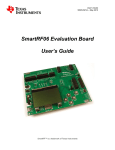
Instabus: It is a decentralized open system, designed to manage and control electrical devices within a facility. It is developed by Berker, Gira, Jung, Merten and Siemens AG. There are about 200 companies of electrical supplies using this communication protocol. The EIB (European Installation Bus) allows all electrical components to be interconnected through an electrical bus. Every component is able to send commands to other components, no matter where they are. A typical EIB network is made of electrical components such as switches, pulsers, electric motors, electrovalves, contactors, and sensors. This electrical bus is made of a 2x2x0.8mm twisted pair cable that connects all devices within the network. The theoretical maximum number of components is 57375 [62]. Although Instabus may offer a large number of components to be connected, again M-‐Bus is preferred due to its simplicity and dedication on meter monitoring. We should mention again, that M-‐Bus is the base for wM-‐Bus and since our employer company is dedicated on wireless solutions, M-‐Bus and wM-‐Bus seemed the only solution The Wireless M-‐Bus (wM-‐Bus),(EN 13757-‐4), as mentioned before, is the wireless variant of standard M-‐Bus and operates in various sub-‐GHz bands with the 868 MHz and the 169 MHz ones, being the most prominent. More about the wM-‐Bus in next chapters. 1.3 Problem Description The wM-‐Bus solution is used in various applications where standard wireless protocols (such as ZigBee) fail, as due to low frequency and simplicity in its implementation, it has long range and greater penetrability as well as low power consumption. The current metering solution which we are called to evolve, already includes sensor and power consumption meters using the ZigBee protocol and the challenge is to obtain measurements with (an emphasis on water and gas) from distant or hard to approach spots, in the sense that meters may be located behind big obstacles, deep underground or on buildings roofs. Our solution, implementing an 868MHz and a 169 MHz wM-‐Bus – ZigBee gateway as well as a standalone 868 MHz and 169 MHz wM-‐Bus, solves the problem of acquiring meter readings from the basement or the roof in a water and gas metering home and/or industrial applications. The figure below presents a scenario where a large establishment, (say a fun park, or water slide park), has various meters distributed in a plot of land. There are ZigBee meters and sensors measuring or controlling devices and wM-‐Bus meters (water meters, gas meters etc.). The ZigBee meters which are out of range of the ZigBee concentrator can use wM-‐Bus to actually reach it, with a wM-‐Bus/ZigBee gateway. Alternatively, a wM-‐Bus meter can reach its concentrator. Every scenario is possible; be it a remote wM-‐Bus meter, a ZigBee meter in a great distance from its coordinator, a ZigBee meter within reaching distance etc. 14 Figure 3 Water slides park scenario-‐ Combination of ZigBee/wMBus 1.4 Aim The aim of this thesis is to establish a ZigBee-‐ wM-‐Bus gateway in the 169 and 868 MHz frequency band as well as a standalone wM-‐Bus meter in the same frequency bands and study and understand its behavior. The bus topology will consist of a meter and a data collector. Various test scenarios will be performed in order to verify which signal strength, packet size and power consumption management of the modules is optimal. The ultimate goal is to acquire deep understanding and experience in wM-‐Bus as wells as receive measurements from an electricity and a water meter. The ZigBee knowledge for the application is provided by our employer company’s years of expertise in ZigBee applications. In that sense, emphasis will be put on the wM-‐Bus implementation. This knowledge will be exploited by our employer company for products (meters and gateways) using wM-‐Bus in the 169 MHz and 868 MHz frequency band. 1.5 Scope The project will include the establishment of a wM-‐Bus-‐ZigBee gateway and the study of the communication of nodes using the wM-‐Bus in various test scenarios. We will not design and develop our own module but use the Adeunis NB169-‐MHz for range tests and basic RF communication and the Texas Instruments CC2538+CC1200 evaluation module for establishing the wM-‐Bus-‐ZigBee gateway. The CC2538+CC1200 EM [8] combines the CC2538 system-‐on-‐chip with the CC1200 sub-‐
GHz RF transceiver. CC2538 [9] combines an ARM Cortex M3 MCU with a 2.4 GHz RF-‐module integrated in the same chip while CC1200 [10] is a very sophisticated RF transceiver working in the 169~920 MHz frequency band. The CC2538+CC1200 EM is connected to the SmartRF06 Evaluation Board [13], a general-‐purpose evaluation board which offers the ability to connect different modules and use various MCUs. This specific board has an on-‐board ARM debugger (XDS100v3 [16]) and flash programmer which means that whatever modules is connected to it, has to have an MCU of ARM architecture. 1.6 Our involvement in MEAZON S.A MEAZON S.A is a technology company that designs smart products that exploit the power of the internet of things. The company designs and develops micro-‐electronic systems and software for the smart, simple and effective management of appliances and facilities in a company or household, 15 remotely, through the user’s smart device or computer. Meazon conducts every step, from the hardware design, to the firmware needed up to the software and the cloud -‐ based interfaces and databases. One of MEAZON’s main products and field of research and development is the energy consumption monitoring but also generally the monitoring of different user or industrial consumption measurements from meter and/or sensors. MEAZON mainly works with ZigBee protocol, implementing various applications from (as mentioned) energy monitoring to various tailored home automations. Our goal but also the reason for our hiring was to study and implement a Wireless M-‐Bus solution which will expand MEAZON’s palette of home / industrial monitoring solutions; a Wireless M-‐Bus based water meter but also expand the reachability of ZigBee devices with a ZigBee-‐ wM-‐Bus gateway. Below we can see our involvement and also the different architectures that are possible with the use of our system. Figure 4 MEAZON's fields and our involvement Figure 5 wM-‐Bus/ ZigBee gateway acts as a ZigBee Node 16 Figure 6 ZigBee nodes forward their measurements over wM-‐Bus to the cloud Figure 7 Out of reach ZigBee nodes use wM-‐Bus to connect to the cloud Figure 8 wM-‐Bus meters communicate with a Gateway or concentrator Finally it is important to show our ultimate goal; the integration of the wM-‐Bus in MEAZON’s energy monitoring / sensor interfacing solutions. The figure below shows the company’s already implemented interface of different sections and the desired expansion through the implementation of wM-‐Bus: 17 Figure 9 Meazon's System Overview -‐ wM-‐Bus is under integration 18 2 The Wireless M-‐Bus 2.1 Introduction The radio variant of M-‐Bus is called Wireless M-‐Bus and is specified in EN 13757-‐4. It is dedicated to the European ISM frequency at 868, 433 and 169 MHz. Devices communicating with Wireless M-‐Bus technology are Figure 10 The Wireless M-‐Bus official classified as either meters or “other” devices: the role of meters is l
to transmit utility consumption data, while “other” devices (also referred to as concentrators) are in charge of collecting those data and can optionally send commands to meters. The basic wireless M-‐Bus architecture is apparent below: Figure 11 Basic wM-‐Bus architecture There are various modes of Wireless M-‐Bus which are obvious in the following table [2]. Table 2 Wireless M-‐Bus modes 19 2.2 The WMBUS modes and sub-‐modes studied and implemented Description of the modes and sub-‐modes we implemented are shown below [17]: Table 2 Modes and sub-‐modes we studied Sub-‐
Way modes Typical application Chip-‐
rate kcps Max duty cycle Data coding + header Description S1-‐m 1 Transmit 32.768 0,02 % Manchester Transmit only; transmits with a duty only meter and short cycle limitation of 0.02 % per hour to for mobile header a mobile or stationary receiving or stationary point. Transmits in the 1 % duty cycle readout frequency band. Requires a continuously enabled receiver. N1a-‐f 1 Long range transmit for stationary readout 2.4 or 4.8 10 % NRZ Transmit only; transmits on a regular basis to a stationary receiving point. 2.2.1 Mode S “Stationary mode", mode S is intended for unidirectional or bidirectional communications between the meter and a stationary or mobile device. A special transmit-‐only sub-‐mode S1 is optimized for stationary battery operated devices with a long header and the sub-‐mode S1-‐m is specialized for mobile receivers. In mode S, the meter sends data spontaneously, either periodically or stochastically. Frame transmission from meters to other devices uses a bit rate of 32.768 kbps, while communication in the opposite direction is carried out also at 32.768 kbps. In Mode S1 the meter doesn’t care if any receiver is present or not. The meter sends data and returns immediately in power-‐save mode without waiting for a response. This is a unidirectional communication. In Mode S2 the meter sends its data and stays awake during a short time immediately after transmission, to listen to a possible response frame. If no response is received, the meter returns in power-‐save mode. If a response is received, then a bidirectional communication link is opened between meter and concentrator. In this project we implemented sub-‐mode S1-‐m without implementing the power saving aspect as our goal was to study the behavior of the protocol. As future work and part of the product’s development, we will move on to implement the much needed power saving feature. Mode S also requires that data is Manchester encoded when “on the air”. We didn’t have to implement a Manchester encoding – decoding utility in software, as this is done in hardware by the CC1200 transceiver. 20 Below we can see specific details about the S-‐mode: Table 3 Mode S, Receiver 21 Table 4 Mode S, Receiver 2.2.2 Mode N “Narrowband VHF” (mode N) is optimized for narrowband operation in the 169 MHz frequency band and is allocated for meter reading and a few other services. There are transmit only sub-‐modes N1a-‐f, and bidirectional sub-‐modes N2a-‐f. The range of sub-‐modes can be extended using repeaters. Sub-‐mode N2g is intended for, but not limited to, long range secondary communication using multi-‐
hop repeaters. It uses narrowband communication in the 169 MHz frequency band. Different sub-‐modes and channels are defined, with different bit rates and modulation types, as listed below: Table 5 Mode N Sub-‐modes and channels Sub-‐mode Channel b N1a, N2a 1a c 169,406250 12,5 4,8 1,5 N1b, N2b 1b 169,418750 12,5 4,8 1,5 N1c, N2c 2a 169,431250 12,5 2,4 2,0 N1d, N2d 2b 169,443750 12,5 2,4 2,0 N1e, N2e 3a 169,456250 12,5 4,8 1,5 N1f, N2f 3b c 169,468750 12,5 4,8 1,5 N2g 0 d 169,437500 50 19,2 2,5 a 1 169,412500 25 a 2 169,437500 25 a 3 169,462500 25 a)
b)
c)
d)
Centre Channel Modulation Frequency Spacing [MHz] [kHz] GFSK [kbps] 4 GFSK [kbps] Frequency Tolerance [± kHz] These channels are optional and reserved for future use or national specific use. Channel designation according to EU commission decision 2005/928/EC. These channels are preferred when meter transmission needs to be retransmitted. This channel may be used for multi-‐hop retransmission of meter data as specified in EN 13757-‐5. The duty cycle for transmission from the meter shall be limited to 0.02 % in this channel. In this project we implemented sub-‐mode N1b in channel 1b (2.4 kbps, GFSK modulation). 22 Below we can see specific details about the N-‐mode: Table 6 Mode N, Transmitter 23 Table 7 Mode N, Receiver Mode N requires NRZ (Non-‐return-‐to-‐zero) encoding of the telegram. Again, the CC1200 transceiver implements NRZ encoding and decoding in hardware. 2.3 The Wireless M-‐BUS packet structure [1] [17] [18] [19] In this thesis we study and implement mode S and mode N. In that sense we will analyze only mode S and N (and not other modes) in order not to overload this work with unnecessary information. EN 13757-‐4:2010 defines two different packet formats, namely format A and B. Multi-‐byte fields described in the following subsections are transmitted least significant byte first, except the CRC fields, which are transmitted most significant byte first. Frame format B is used in Modes C and F, so we will not be analyzing this frame format in this paper. 2.3.1 Frame Format A This format can be used in both S-‐ and N-‐mode of the Wireless M-‐Bus. Radio frames with this format are composed of a number of blocks, as illustrated in the figure below [1]. Table 8 Frame Format A Below, the different blocks of Frame Format A are explained more thoroughly. 24 x
Block 1 Table 9 Block 1 format x
Block 2 Table 10 Block 2 format x
Block n Table 11 Block n format 2.3.2 Field definitions and explanations 2.3.2.1 Preamble The preamble is used for synchronization between transmitter and receiver; the EN 13757-‐4 specification imposes a minimum limit for preamble length, which depends on the mode used: 9 Mode S: 6 bytes if short preamble is used, otherwise 72 bytes (long preamble). In our implementation (S1-‐m) we use short preamble (6 Bytes). 9 Mode N: preamble length depends on the modulation used (4 bytes for GFSK and GMSK, 8 bytes for 4GFSK). In our implementation, we use GFSK modulation, so preamble is 4 bytes. 2.3.2.2 Block 1 x
x
x
x
x
L-‐field is the length indication. In frame format A this field does not include the length of CRC-‐fields. C-‐field is the communication indication (request, send, response expected, ACK…) M-‐field is the Manufacturer ID of the sending device A-‐field is the address of the sending device and is composed of the concatenation of an identification number (4 bytes), a version code (1 byte) and a device type code (1 byte) CRC-‐field is the Cyclic Redundancy Check Below we analyze each field of Block 1: 25 9 Communication Indication (C-‐Field) Table 12 Function Codes of the C-‐field in messages sent from primary station [17] 26 Table 13 Function codes of C-‐field in messages sent from secondary stations 9 Manufacturer ID (M-‐field) The third and the fourth byte of the first block shall contain a unique User/Manufacturer ID of the sender. The 15 least significant bits of these two bytes shall be formed from a three letter ISO 646 code (A…Z) as specified in Clause 5.6 of EN 13757-‐3:2012 [18]. See [19] [63], for administration of these three letter codes. If the most significant bit of these two bytes User/Manufacturer ID is equal to zero, then the address A shall be a unique (hard coded) manufacturer meter address of 6 bytes. Each manufacturer is responsible for the worldwide uniqueness of these 6 bytes. Any type of coding or numbering, including type/version/date may be used as long as the ID is unique. If the most significant bit of this two-‐byte User/Manufacturer ID is different from zero, then the 6 byte address shall be unique at least within the maximum transmission range of the system (soft address). This address is usually assigned to the device at installation time. As long as these unique address requirements are fulfilled, the remaining bytes may be used for user specific purposes. NOTE: The address is used to identify the meter independently of its communication interface. Therefore the manufacturer has to assure a uniqueness of the addresses not only for wireless meters but for all produced meters. 9 Address (A-‐field) This address field A contains, in deviation to EN 60870-‐5-‐2 [19], always the address of the sender. At uplink -‐ the address of a Meter with integrated radio module or the address of a radio adapter supporting a Meter without a radio module and at downlink the address of the Other Device. The address shall be (and each User/Manufacturer shall guarantee that this address is) unique. If this protocol is used together with the Transport Layer or the Application Layer of EN 13757-‐3 [18], then the following Address structure shall be applied: the A-‐field shall be generated as a concatenation of the 'Identification number', 'Version number' and 'Device type information'. 27 NOTE: If the meter address differs from the sender address, the meter address will be transmitted after the CI-‐field using a long Transport Layer [18]. 9 Cyclic redundancy check (CRC-‐field) The CRC shall be computed over the information from the previous block, and shall be generated according to FT3 of EN 60870-‐5-‐1 [20].The formula is: x
x
x
The CRC polynomial is: ݔଵ + ݔଵଷ + ݔଵଶ + ݔଵଵ + ݔଵ + ଼ ݔ+ ݔ+ ݔହ + ݔଶ + 1 The initial value is 0 The final CRC is complemented 2.3.2.3 Block 2 9 Control information field (CI-‐field) CI-‐field is the Control Information to indicate the protocol used to the upper layer. The first byte of the second block is the CI-‐field. The CI-‐field specifies the type of protocol and thus the nature of the information that follows. It specifies the structure of the next higher protocol layer. It may declare an Application Layer, a Transport Layer, a Network Layer or an Extended Link Layer. The format of the C-‐field (or control field) is described below: Table 14 Format of the CI-‐Field The meaning of bits 5 and 4 depends on the value of bit 6 (PRM): when PRM is set to 1, bits 5 and 4 are interpreted as FCB and FCV fields respectively, otherwise the same bits carry ACD and DFC fields. x
x
x
x
x
RES is a reserved bit and should be set to 0 PRM indicates if the frame is being sent from a primary to a secondary station (when set to 1) or vice versa (when set to 0); the role of meters and concentrators as primary or secondary stations is defined by the application FCB (Frame Count Bit) is used to detect frame duplication: its value should alternate between 0 and 1 for successive frames sent from a primary station to the same secondary station; in order to set a common starting value of this bit for a given pair of stations, a link reset frame is defined (function code 0) which indicates to the receiving secondary station that the next frame from the primary station will have FCB set to 1 FCV (Frame Count Valid) in frames sent from a primary station indicates whether the duplication detection mechanism of the frame count bit is used (when set to 1) or not (when set to 0) ACD (ACcess Demand), if set to 1, indicates that the sending secondary station has high priority data available, which should be requested by the primary station 28 x
x
DFC (Data Flow Control), if set to 1, indicates that the sending secondary station may not be able to process further frames sent by the primary station; it can be used as a flow control mechanism to prevent data overflow at the secondary station Function is a numeric code indicating the type of frame being sent; its meaning depends on the direction of communication (primary to secondary or vice versa) All higher protocol layer messages have a variable length. The length information is part of the link layer. It shall be known to the application layer in order to properly terminate its decoding of each datagram. Each message starts with a one-‐byte CI (control information) field, which distinguishes between various message types and application functions and header length. It is also used to distinguish between true application layer communication and management commands for lower layers. The meaning of the remaining bytes of the message depends also on the value of the CI-‐field. The fixed header structures after CI-‐Fields are: x
No fixed header (None) (0 bytes): as for CI=78h, x
Short header (4 bytes or more): as for CI=7Ah, x
Long header (12 bytes or more): as for CI=72h, A sample of values of the CI-‐field shall be used as specified in the table below: 29 Table 15 Sample of CI-‐Field codes used by the master or the slave For the full table see Appendix. 9 Data-‐ Field The Data Field contains the useful data (metered values, clock, alarm etc.), which are preceded by a Data Header. As shown in 2.3.1 the data in block 2 are 15 bytes long followed by a CRC. We will elaborate more on the data field in section 2.3.4. 2.3.2.4 Block n It contains a 16 – byte data field along with a 2-‐byte CRC. A frame can have multiple blocks with the format of Block n; their number depends on the length of the data field. 2.3.3 Extended Link Layer (ELL) When the CI-‐field assumes the values 0x8C or 0x8D, the first bytes of the Data-‐field contain an extended link layer, which is followed by another CI-‐field and then the application data. The extended link layer can have one of two formats. The first is illustrated below and is present when the CI-‐field is set to 0x8C. Table 16 Format of the ELL when CI = 0x8C 30 The second format is present when the CI-‐field is set to 0x8D and is illustrated below: Table 17 Format of the ELL when CI = 0x8D 9 CC is a communication control field and is coded using the following bitmask: Table 18 Communication Control Field (CC field) x
x
x
x
x
B-‐field, when set to 1, indicates that the sending device implements bidirectional communication RD-‐field controls the response delay of the responding device, indicating whether a fast (RD-‐field set) or slow (RD-‐field cleared) response delay should be used S-‐field, when set to 1, indicates a synchronized frame R-‐field, when set to 1, indicates that the frame has been relayed by a repeater P-‐field, when set to 1, indicates a high priority frame 9 ACC is the access number and is used to detect duplicate frames and to associate request and response frames. 9 SN (Session Number) is a 4 byte field (transmitted least significant byte first) with the following content: Table 19 SN content x ENC-‐field specifies the encryption method, with the value 0 meaning no encryption and the value 1 meaning AES-‐128 Counter Mode encryption; other values are reserved for future use. If AES-‐128 Counter Mode is used, the remaining bytes of the frame, from and including the PayloadCRC (see below) field (but excluding the CRC fields), will be encrypted. x Time-‐field is a relative minute counter and is used together with the Session-‐field to ensure that the encrypted transmission is protected from replay attacks x Session-‐field is a zero-‐based index of the communication session within the minute specified by the Time-‐field 9 PayloadCRC is a cyclic redundancy check, covering the remainder of the frame (excluding the CRC fields). 31 2.3.4 Data Field If the application layer defined by EN 13757-‐3 is used, depending on the value of the CI-‐field, the first bytes of the Data-‐field may contain a data header. Three types of data header (none, short and long) are defined. 2.3.4.1 Data Header ¾ Structure of none Data Header Structure of short Data Header ¾ Structure of long Data Header 32 Table 20 Sample of Device Identification Codes For the full table see Appendix. 33 ¾ Configuration field: contains information about the encryption mode and the number of encrypted bytes. Depending on the mode it may contain additional information about: 9 meter accessibility 9 contents of the message 9 repeated wireless datagrams 9 synchronous wireless transmissions 34 If no functionality of the Configuration field is used its value shall be 0000h. The table below shows where to find the mode bits. The number of encrypted bytes is contained in the low byte of the configuration word (bit 0 – bit 7). The exact coding of those bits depends on the mode. Table 21 General Definition of the Configuration Field 2.3.4.2 Encryption Structure of encrypted messages 35 Table 22 Definition of mode bits (encryption method)
2.3.4.3 Variable Data Blocks (Record) 36 Table 23 Data Field Structure 37 38 NOTE: For the full table of Primary VIF codes see Appendix [25]. 2.4 Meter – Gateway (“Other”) Communication Having described the basic structure of a wM-‐Bus message, we move on to describe how a meter communicates with a gateway (concentrator, collector etc.). There are several ways a meter can communicate with an “other” (meaning gateway, collector etc.). In Table 12, we can see the different kinds of messages exchanged in connection with the C-‐field (see 2.3.2.2). In Table 12 we can also see the different functions of the messages, their direction, as well as their confirmation messages (if any). We will try to make the reader understand the basic transactions, by presenting them in a way that their connection and their functionality is better presented. x
SND-‐NKE: The “other” sends a link reset to the meter after communication when it intends to finish communication. Doesn’t need confirmation. Mandatory for modes S2, T2, C2, R2, N2, F2. Figure 12 SND-‐NKE Transaction x
SND-‐NR: The meter sends on-‐demand/periodical application data without request (Send/No Reply). Doesn’t need confirmation from “other”. Mandatory for modes S1, N1. Figure 13 SND-‐NR Transaction x
ACC-‐NR: The meter sends on-‐demand/periodical message to provide the opportunity of access to itself (contains no application data). Figure 14 ACC-‐NR Transaction 39 x
SND-‐IR: The meter sends manually initiated installation data (Send Installation Request). Confirmed by CNF-‐IR (see below). Figure 15 SND-‐IR/CNF-‐IR Transaction x
x
CNF-‐IR: Confirms the successful registration (installation) of meter to service tool, (contains no application data). SND-‐UD / SND-‐UD2: 9 If “other” sends a SND-‐UD, it sends a command to the meter. The meter responds with an ACK or an ACK long (see below), depending on the SND-‐UD content. 9 If the “other sends” a SND-‐UD2 (SND-‐UD with C-‐field=43h), it sends a command to the meter but the meter assumes that it has received a subsequent REQ-‐UD2. In that case it won’t respond with an ACK but with RSP-‐UD, instead. Figure 16 SND-‐UD/ ACK, RSP-‐UD Transaction x
x
ACK / ACK long: Acknowledgement from the meter to the “other” of user data (e.g. set time) REQ-‐UD1 / REQ-‐UD2 : 9 If other sends a REQ-‐UD1, it means that it requests alarm data from the meter. Thus the meter shall respond with RSP-‐UD (see below), which will contain the desired information. 9 If other sends a REQ-‐UD2, it means that it requests data from the meter. Then, the meter will again answer with RSP-‐UD (If the meter doesn’t support alarm data, it responds with an ACK) Figure 17 REQ-‐UD/RSP-‐UD Transaction x
RSP-‐UD: Since the meter has received a request, it responds with a message containing user data 40 x
ACC-‐DMD: Access demand from Meter to Other Device. This message requests an access to the Meter (contains no application data) Figure 18 ACC-‐CMD / ACK Transaction x
ACK: Acknowledgement from the meter to the “other” 41 3 The ZigBee As mentioned before, Meazon’s S.A main field of interest is around ZigBee and its interface with different network protocols, devices and eventually different users. Meazon’s flagship product is the Meazon Izy Plug, as smart device that can receive measurements (voltage, current, frequency etc.) from an electrical outlet and transport them over ZigBee to other devices. (More about the Meazon Izy Plug in 4.5.1). Although our study and implementation didn’t involve studying the ZigBee wireless protocol, we should present some basic information about the ZigBee network, so as the reader can have a broader understanding of why the protocol is really important and how it can interface with wireless M-‐Bus. ZigBee is a low-‐cost, low-‐power, wireless mesh network standard. The low cost allows the technology to be widely deployed in wireless control and monitoring applications. Low power usage allows longer life with smaller batteries. Mesh networking provides high reliability and more extensive range. ZigBee operates in the industrial, scientific and medical (ISM) radio bands with the 2.4 GHz frequency band being the most prominent. Data transmission is up to 250 kilobits/second in the 2.4 GHz band. The ZigBee network layer natively supports both star and tree typical network topologies but also generic mesh networks. Every network must have one coordinator device, tasked with its creation, the control of its parameters and basic maintenance. Within star networks, the coordinator must be the central node (and the only one in each network). Both trees and meshes allow the use of ZigBee routers to extend communication at the network level. The “leafs” of a ZigBee tree network are the end-‐devices which usually are battery operated devices (usually sleeping or being in low power mode and periodically “waking-‐up” to collect and/or send pending messages). The following figure shows the role of each of the mentioned devices in a ZigBee network in 3 different topologies. Figure 19 ZigBee Network devices and topologies [45] ZigBee builds upon the physical layer and media access control defined in IEEE standard 802.15.4 (2003 version) for low-‐rate WPANs. The specification goes on to complete the standard by adding four main components: network layer, application layer, ZigBee device objects (ZDOs) and 42 manufacturer-‐defined application objects which allow for customization and favor total integration. The ZigBee Protocol stack can be seen in the figure below: Figure 20 ZigBee Protocol Stack [46] Besides adding two high-‐level network layers to the underlying structure, the most significant improvement is the introduction of ZDOs. These are responsible for a number of tasks, which include keeping of device roles, management of requests to join a network, device discovery and security. ZigBee is not intended to support power-‐line networking but to interface with it, at least for smart metering and smart appliance purposes (suitable for our smart meter product). Because ZigBee nodes can go from sleep to active mode in 30 ms or less, the latency can be low and devices can be responsive, particularly compared to Bluetooth wake-‐up delays, which are typically around three seconds. Because ZigBee nodes can sleep most of the time, average power consumption can be low, resulting in long battery life. Texas Instruments provides developers with a Real Time Operating System called ZStack in order to develop their ZigBee applications on various platforms with different architectures. ZStack comes to serve several profiles (flavors), each one of them configured specifically for the type of product/application it is going to be used on. Some of the most known profiles Texas Instruments supports are: x
x
x
ZigBee Home Automation ZigBee Light Link ZigBee Smart Energy 43 The firmware libraries that come with TI’s ZStack, include some hardware abstraction layer drivers (HAL), ZigBee Network and MAC layers management tasks, ZDO layer management as well as ZigBee application libraries and functions, providing space for further development of manufacturer specific applications. The profiles mentioned above are described by the ZigBee Alliance and are accompanied by several guidelines so that any ZigBee Certified product can be compatible and interoperable with all the rest. As described by the ZigBee Alliance, for the ZigBee Application Layer, each ZigBee node is required to have some application endpoints which provide a communication API with the node’s application layer. Endpoints serve three purposes in ZigBee. They: • Allow different application profiles to exist within each node • Allow separate control points to exist within each node • Allow separate devices to exist within each node Under each endpoint there exists a number of Clusters. Clusters, defined by a 16-‐bit identifier, are application objects. Whereas the Nwk Address and endpoint are addressing concepts, the cluster defines application meaning. For example, a commonly used cluster is the OnOff Cluster (ID 0x0006). This cluster’s functionality is to turn a device on or off. Each cluster contains a set of attributes and commands. These attributes can be read, written or reported by a ZigBee node. In that way, Clusters encapsulate both commands and data. A ZigBee application can determine whether a device is on or off by querying the OnOff Attribute within the OnOff Cluster in a node endpoint, or it can set the state of that device by commanding the cluster to turn the device on, off, or toggle it. 44 4 Range tests with the ADEUNIS NB169 modules 4.1 The NB-‐169 MHz module One of the RF transceiver modules used is the NB169 by Adeunis. As a first step we worked with NB169 modules so as to gain some experience in basic RF communication. We performed range tests around the facility of our employer company’s offices and came to valuable conclusions about the range and the penetrability of a 169 MHz RF signal. This module was chosen by our employer company, as the most suitable solution in terms of quality, low cost and support community for the RF range tests and the basic RF communication. A TRA169 Rubber antenna was used which leads to an SMA connector which in turn is connected to the specified antenna pin on the NB169 using a UF.L connector. Below we can see the pinout of the NB169 chip as well as the TRA169 Rubber Antenna: Figure 21 TRA169 Rubber Antenna Figure 22 NB169 pinout Table 24 RF data rates and corresponding channels The table above [3] helps users configure their NB169 modules so as to obtain the longest possible range at the highest possible output power (500mW in the 169.40625 to 169.49375MHz band). In that sense, depending on the RF data rate between the module and the MCU, different frequencies are available. 45 4.2 Enabling the ADEUNIS NB-‐169 MHz modules As a first step, we connected the NB169 Module directly to a serial output in order to be able to communicate with it, using the AT commands provided by Adeunis. On a breadboard we connected the Adeunis NB169-‐MHz module to a MAX3232 RS232-‐
Serial Port-‐to-‐TTL (by LC Technology), so as to be able to write the AT commands and receive the answer in a terminal (Tera Term [29] and RealTerm [30] were used). THE MAX3232 was connected to Z-‐TEK USB 2.0-‐
Figure 23 A Z-‐TEK USB to Serial Port connected to a to-‐RS232 converter. The MAX3232 module, shown in TTL-‐RS232 module figure 23 along with Z-‐TEK, is responsible for the “translation” of the RF module’s TTL-‐logic signals (0-‐3.3 V) to an RS232 [55]. The UART was set to function at 38400 baud data rate, with 8-‐N-‐1 configuration. 8-‐N-‐1 is a common shorthand notation for serial port parameter settings or configuration in asynchronous mode, in which there are eight (8) data bits, no (N) parity bit, and one (1) stop bit. Using the AT commands, we could enable the module, write to its registers and configure various parameters such signal strength, chosen channel or RF data rate. Table 25 Example of AT commands for the NB169 4.2.1 The evaluation board – Our part Our employer company already had plans to develop its own evaluation gateway-‐board so as to perform tests and evaluate the behavior of many different modules (GPRS, ZigBee and others) which are used in various products and applications of the company. From our part, our contribution to the development of this board was the hardware design and the connection of the NB169 module with the microprocessor of the gateway-‐evaluation board, a Texas Instruments CC2531. Below are the schematics concerning the connection of the NB169 to the TI CC2531. At this point it was crucial to thoroughly study the datasheets of TI CC2531 and NB169 so as to fully understand how the connections should be made and which peripheral electrical parts should be chosen (resistors, capacitors etc.). The specifications for the NB169 dictate that the module should be connected to the MCU over UART so we had to connect our module to the corresponding port and pins of the TI CC2531. For the development of the schematic we used Altium Designer [31] with the collaboration of our colleague -‐ head of the company’s hardware department so as to combine the different parts needed for the evaluation board. 46 Figure 24 NB169 Schematic part on the board Figure 25 CC2531 Schematic part on the Board 47 Eventually the following gateway-‐evaluation board was produced: Figure 26 Gateway evaluation PCB As someone can see, the board has various slots for different modules but only one module can be active at a time. The module chosen can be activated with the use of a jumper located close to every module slot. The figure above shows the board with the Adeunis module already soldered on the board. 4.3 Communication of two modules and range tests Using two evaluation boards with the two Adeunis modules, we were able to conduct range tests. In one module, the TRA169 Rubber Antenna was connected whereas the lack of a second Antenna led us to make one of our own. With basic antenna physics we made a hand-‐made monopole antenna for 169 MHz, measuring wavelength/4 in length (ʄ/4 rule.)
ɉ = , where c (speed of light) =2.99792458E8 m/s, f=frequency
So for a 169 MHz, we needed a (ʄ/4=) 44.3 cm wire. [11] As we had no interest in learning how to program the TI CC2531, we proceeded as follows. Having the MCU in reset, and the modules connected to the serial port we were able to “talk” directly to the modules using AT commands. Configuring one module to transmit mode and the other to receive mode, we were able to exchange ASCII characters (in substance “chat”) between the two modules from different positions and distances. Writing a small script in Python, that enabled the serial terminal to answer every time there was an incoming packet, was also helpful. Figure 27 Our hand-‐made antenna 48 We took various measurements, walking around the two blocks surrounding the company’s offices. Below we can see some of the different positions measured.[12] Figure 28 Two buildings between the two RF modules In the figure above, we can see that the measurement was taken behind a quite big obstacle including two buildings with a garden between them. At that point, the signal was quite weak and some packets were lost. Moving further away in the Ippodamou-‐Thermopilon street corner (see figure), where three buildings are in beetween, resulted in the connection to be lost, but to be regained when we came to the next corner, where there were less obstacles. Figure 29 Two buildings between the two RF modules 49 The measurement of the figure above, was taken from the opposite direction where two buildings (including our own) were also between the communicating nodes. The results here, were much better as we had almost zero packet loss. Especially when moving the node (located in the company’s building) on the roof, then the signal strength was very satisfying. Figure 30 Line-‐of-‐sight test The above measurement was taken to test line-‐of-‐sight range. Beyond that point we were losing line-‐of-‐sight and had to move to a higher point which at that moment was impossible to reach. Nonetheless, at around 210 meters, as the figure shows, we had zero packet loss. Finally we conducted tests within the building of the company’s offices, taking measurements from different floors, the roof and the basement (our office is on the first floor of a three-‐storey building). Here we had no problems, zero packet loss and satisfactory signal strength. We believe that with the use of a better antenna (we remind that the second antenna was hand-‐
made), the measurements would be better. 50 5 Our System After performing the range tests with the ADEUNIS NB169 modules, changes in the company’s strategy and a new collaboration with Texas Instruments, led us to work with the SmartRF06 Evaluation Board and the CC2538+CC1200 EM, focusing on a different (architecture-‐wise) MCU, the Texas Instruments CC2538. Both boards are provided by Texas Instruments. We will describe the characteristics of the boards in section 5.2. 5.1 Abstract System Description As mentioned before, we implemented S1-‐m and N1 mode with the optional feature of an installation request and a confirmation by the concentrator (“other”). However, we didn’t evolve in the implementation of power modes for the meters and concentrator, as this has to be conducted in collaboration with the hardware designer of our employer company mainly for the election of the battery that will be used in a real water meter system. Thus, integrating power management in our project, has been left for future work. Our implementation can be summarized as: 9 Receiving measurements from an electricity meter (more specifically a Meazon Izy-‐Plug [27]) over ZigBee and forwarding them via wM-‐BUS to a concentrator. In turn, the concentrator forwards the desired data to a serial output (UART). This interface was implemented in both S1m mode (868 MHz) and N1 mode (169 MHz). 9 Receiving measurements from a water meter by pulse counting and forwarding them via wM-‐BUS to a concentrator. In turn, the concentrator forwards the desired data to a serial output (UART). This interface was implemented in both S1m mode (868 MHz) and N1 mode (169 MHz). In all cases the UART can either be connected to a PC or other. In our implementation the UART is connected to Meazon Gateway Advanced which is essentially a BeagleBone [28], with a custom-‐
built shield designed by Meazon. For the information of the reader, we mention that the BeagleBone can receive shield boards with its specifically–designed headers. Our shield serves various functionalities so as to acquire measurements from a variety of different protocols. More about the Meazon Gateway Advanced (from now on MGA) in 4.3.3. Below we can see the different systems overview: Figure 31 Electricity Meter (plug) system overview in both S-‐ and N-‐ mode 51 Figure 32 Water Meter system overview in both S-‐ and N-‐ mode We should note that the UART is connected to the PC following the same procedure as in 4.2 5.2 The Boards 5.2.1 The SmartRF06 Evaluation Board The platform on which our system was implemented is the SmartRF06 Evaluation Board (from now on SmartRF06 EVB). The platform’s technical characteristics are apparent in the following figures: Figure 33 SmartRF06 Evaluation Board 52 Figure 34 High level overview of board architecture As it is obvious, the SmartRF06 EVB offers various peripherals which, among others, include an LCD screen, an SD card reader, test LEDs, test buttons, an accelerometer and a light sensor for various user interfaces. The board also features an XDS100v3 Emulator, which works as a debugger and flash programmer for ARM-‐based MCUs as well as a serial monitor. Consequently, with the use of a single micro-‐USB connection, a debugger and a virtual monitor are available. On the upper-‐left corner of the SmartRF06 EVB, one can see two break-‐out connectors to which the user can attach different ARM MCU-‐based evaluation modules. In order to test the board we used two different evaluation modules: The CC2538EM [14] and the CC2538+CC1200 EM. The use of CC2538EM was quite limited. We only run some example projects provided by TI “playing” with the various parameters and witnessing the corresponding results on the board. The experiments included lighting a LED with the push of a button, writing to the LCD screen or using the light sensor on the SmartRF06 EVB, to generate an interrupt. Acquiring some experience with programming the CC2538 (while waiting for the CC2538+CC1200 modules to be delivered from our partner company), helped us move on to the programming of the new modules, when they finally arrived. Figure 35 CC2538EM 53 5.2.2 The CC2538+CC1200 Evaluation Module The CC2538+CC1200 Evaluation Module (from now on CC2538+CC1200 EM), as mentioned before, includes a CC2538 system-‐on-‐chip and CC1200 RF sub-‐GHz transceiver. CC2538 is a very-‐low-‐power system on chip solution for 2.4-‐ GHz IEEE 802.15.4 and ZigBee Applications. It combines an ARM Cortex-‐M3 based processor core along with an RF module tuned for the 2.4 GHz frequency band. Thus, it is ideal for us, so as to connect to a ZigBee network. Figure 36 CC2538+CC1200 EM CC2538+CC1200 Evaluation Module On the other hand CC1200 is a sub-‐GHz transceiver which can operate in various frequency bands from 164 MHz up to 950 MHz. According to the abovementioned information, it’s quite understandable why this board is ideal for our application, a ZigBee-‐WM Bus gateway or a stand-‐alone wM-‐Bus metering solution. We will expand more on CC2538 and CC1200 in chapter 5.3. 5.2.3 The STEVAL-‐IKR002V4SPIRIT1 -‐ 868 MHz KIT and the WM-‐Bus Application We should also mention that we conducted experiments with STEVAL-‐IKR002V4SPIRIT1 evaluation board, along with 868 MHz daughter boards and the wM-‐BUS-‐dedicated “WM-‐Bus Application” by STMicroelectronics. The reason for this was to acquire more experience with an already embedded wM-‐Bus stack and verify our attempts to establish a fully functional wM-‐Bus. The STEVAL-‐IKR002V4SPIRIT1 kit has two STM32L microcontroller-‐based motherboards on which the user can attach SPIRIT1 low power sub-‐GHz RF transceiver daughterboards, tuned for the 868 MHz band or other frequencies [40]. We were also supplied with a 169 MHz daughterboard, but eventually didn’t use it. In short the boards allow the establishment of a wM-‐Bus communication between them. What we did was to try to interface with them using our boards. We actually managed to interface up to a basic level (S-‐mode preambles and wM-‐Bus settings were correct) but the messages received in SmartRF™ Studio 7 (see 4.4.1) were incomprehensible at first. It is important to note that if the basic wM-‐Bus S-‐mode settings (S-‐ mode preamble, S-‐mode sync word etc.) were incorrect, SmartRF™ Studio 7 would discard the messages. Eventually we managed to decipher the data received and thus realized we were moving to the correct direction. However the fact that the messages sent by the STEVAL-‐IKR002V4SPIRIT1 boards were Viterbi encoded, discouraged us to spend more time on this attempt for further verification, as we had no easy way of Viterbi decoding the incoming data. The boards were programmed with J-‐Link debuggers by Segger. [39] The WM-‐Bus application allows the user to interface with the two boards; one board plays the role of the meter and the other plays the role of the concentrator. The user can then “install” the “meter” to the concentrator’s devices and configure both boards desirably. The sniffer functionality, which was also a reason for acquiring the STMicroelectronics solution, was eventually not available and according to of STMicroelectronics’s website it is still under development. In figure 39 we can see the “Meters” sub-‐screen of the WM-‐Bus Application. 54 Below we can see the STEVAL-‐IKR002V4SPIRIT1 evaluation boards, the daughter boards along with a WM-‐Bus Application screenshot. Figure 38 shows that the 169 MHz daughterboard is essentially the same as its 868 MHz counterpart, but a resistor is placed in a different position. Figure 37 STEVAL-‐IKR002V4SPIRIT1 -‐ 868 MHz KIT Figure 38 SPIRIT1 Daughter Board Detail 55 Figure 39 WM-‐Bus Application screenshot -‐ Meters sub-‐screen 5.3 The Chips In this chapter we will elaborate more on the chips with which the CC2538+CC1200 EM is equipped; the CC2538 SoC and the CC1200 RF transceiver. 5.3.1 The CC2538 System-‐On-‐Chip As stated in the official Texas Instruments website: The CC2538 chip “[…] combines a powerful ARM Cortex-‐M3-‐based MCU system with up to 32KB on-‐chip RAM and up to 512KB on-‐chip flash with a robust IEEE 802.15.4 radio. This enables the device to handle complex network stacks with security, demanding applications, and over-‐the-‐air download. Thirty-‐two GPIOs and serial peripherals enable simple connections to the rest of the board. The powerful security accelerators enable quick and efficient authentication and encryption while leaving the CPU free to handle application tasks. The low-‐power modes with retention enable quick startup from sleep and minimum energy spent to perform periodic tasks […].” [9]. CC2538, among others, features: 56 Figure 40 CC2538 System-‐On-‐Chip x
For the Microcontroller 9 Powerful ARM® Cortex®-‐M3 with Code Prefetch 9 512KB, 256KB or 128KB of In-‐System-‐ Programmable Flash 9 Up to 32KB of RAM (16KB with Retention in All Power Modes) 9 Supports Dual ZigBee Application Profiles 9 Up to 32-‐MHz Clock Speed 9 cJTAG and JTAG Debugging 9 Supports On-‐Chip Over-‐the-‐Air Upgrade (OTA) x
For the RF 9 2.4-‐GHz IEEE 802.15.4 Compliant RF 9 Excellent Receiver Sensitivity of –97 dBm Transceiver 9 Robustness to Interference With ACR of 44 9 Programmable Output Power up to 7 dBm dB x
For Security 9 Future Proof AES-‐128/256, SHA2 Hardware 9 Optional – ECC-‐128/256, RSA Hardware Encryption Engine Acceleration Engine for Secure Key Exchange 9 Radio Command Strobe Processor and Packet Handling Processor for Low-‐Level MAC Functionality x
Low Power Features 9 Active-‐Mode RX (CPU Idle): 20 mA 9 Active-‐Mode TX at 0 dBm (CPU Idle): 24 mA 9 Power Mode 1 (4-‐µs Wake-‐Up, 32-‐KB RAM 9 Power Mode 2 (Sleep Timer Running, 16-‐KB RAM Retention, Configuration Register Retention, full Register Retention): 0.6 mA Retention): 1.3 µA 9 Power Mode 3 (External Interrupts, 16-‐KB 9 Wide Supply-‐Voltage Range (2 V to 3.6 V) RAM Retention, Configuration Register Retention): 0.4 µA x
Peripherals 9 12-‐Bit ADC With 8 Channels and 9 Battery Monitor and Temperature Sensor Configurable Resolution 9 4 × General-‐Purpose Timers (Each 32-‐Bit or 9 USB 2.0 Full-‐Speed Device (12 Mbps) 2 × 16-‐Bit) 9 32-‐Bit 32-‐kHz Sleep Timer 9 2 × SPI 9 µDMA 9 2 × UART 9 32 General-‐Purpose I/O Pins 9 I2C 9 Watchdog Timer 57 Below we can see the chip’s architecture: Figure 41 CC2538 architecture 58 5.3.2 The CC1200 RF sub-‐GHz transceiver The CC1200 on the other hand, is “[…] a fully integrated single-‐chip radio transceiver designed for high performance at very low-‐power and low-‐voltage operation in cost-‐effective wireless systems. All filters are integrated, thus removing the need for costly external SAW and IF filters. The device is mainly intended for the ISM (Industrial, Scientific, and Medical) and SRD (Short Range Device) frequency bands at 164–190 MHz, 410–475 MHz, and 820–950 MHz. The CC1200 device provides extensive hardware support for packet handling, data buffering, burst transmissions, clear channel assessment, link quality indication, and Wake-‐On-‐Radio. The main operating parameters of the CC1200 device can be controlled through an SPI interface. In a typical system, the CC1200 device will be used with a microcontroller […]. ” [10] CC1200, among others, features: x
RF and Analog High-‐Performance, Single-‐Chip Transceiver 9 Receiver Sensitivity: –123 dBm at 1.2 9 Adjacent Channel Selectivity: Up to 60 kbps,–109 dBm at 50 kbps dB at 12.5-‐kHz Offset 9
Blocking Performance: 86 dB at 10 MHz 9 Very Low Phase Noise: –114 dBc/Hz at 10-‐kHz Offset (169 MHz) Programmable Output Power Up to +16 dBm with 0.4-‐dB Step Size Automatic Output Power Ramping Supported Modulation Formats: 2-‐FSK, 2-‐GFSK, 4-‐FSK, 4-‐GFSK, MSK, OOK Supports Data Rate Up to 1.25 Mbps in Transmit and Receive x Low Current Consumption Enhanced Wake-‐On-‐Radio (eWOR) Functionality for Automatic Low-‐Power Receive Polling WŽǁĞƌŽǁŶ͗Ϭ͘ϭϮʅ;Ϭ͘ϱʅǁŝƚŚĞtKZdŝŵĞƌĐƚŝǀĞͿ 9 RX: 23 mA Peak Current in High-‐
9 RX: 19 mA Peak Current in Low-‐Power Mode Performance Mode 9 TX: 46 mA at +14 dBm 9 RX: 0.5 mA in RX Sniff Mode x Digital Features: 9 WaveMatch: Advanced Digital Signal Processing for Improved Sync Detect Performance 9 Support for Auto-‐Acknowledge of Received Packets 9 Security: Hardware AES128 Accelerator 9 Digital RSSI measurement 9 Automatic Clear Channel Assessment (CCA) for Listen-‐Before-‐Talk (LBT) Systems 9 Built-‐in Coding Gain Support for Increased Range and Robustness 9 Support for retransmission 9 Data FIFOs: Separate 128-‐Byte RX and TX 9 Includes Functions for Antenna Diversity Support 9 Improved OOK Shaping for Less Occupied Bandwidth, Enabling Higher Output Power While Meeting Regulatory Requirements x Dedicated Packet Handling for 802.15.4g: 9 CRC 16/32 9 FEC, Dual Sync Detection (FEC and non-‐
FEC Packets) 9 Whitening 59 Below we can see the transceiver’s functional diagram: Figure 42 CC1200 functional diagram CC1200 also offers four free GPIO pins that are available for interrupt generation by the transceiver to an MCU or by the MCU to the transceiver. The types of the interrupt are predefined and configuring the corresponding register, the transceiver can create or receive one of those interrupts. For example, an interrupt can be triggered when a TX FIFO threshold is exceeded (thresholds are also configurable) or an interrupt can trigger the transceiver to wake-‐up from low power and receive data to be transmitted. Below we can see the CC1200 pin-‐out and the GPIOs in question: Figure 43 CC1200 pin out -‐ GPIO 0/1/2/3 in red square 60 5.3.3 Meazon Gateway Advanced – BeagleBone 61 Figure 44 Meazon Advanced Gateway 5.4 Software Used 5.4.1 SmartRF™ Studio 7 In order to have deeper understanding of the CC1200 transceiver we used SmartRF™ Studio 7. This specific platform enables the user to have direct access to different transceivers developed by Texas Instruments and configure them desirably [15]. In the TI’s website it is stated: “[…] SmartRF™ Studio is a Windows application that can be used to evaluate and configure Low Power RF-‐ICs from Texas Instruments. The application will help designers of RF systems to easily evaluate the RF-‐ICs at an early stage in the design process. It is especially useful for generation of configuration register values, for practical testing of the RF system and for finding optimized external component values. SmartRF Studio can be used either as a standalone application or together with applicable evaluation boards that are shipped in the RF-‐IC development kits […]”. The platform, among others, features: x
x
x
x
x
x
x
x
Link tests. Send and Receive packets between nodes. Antenna and radiation tests. Set the radio in continuous TX and RX states. A set of recommended/typical register settings for all devices. Read and write individual RF registers. Detailed information about the bit fields for each register. Save/Load device configuration data from file. Exports register settings to a user definable format. Communication with evaluation boards through USB port or the parallel port. [41] The figures below show the SmartRF™ Studio 7 interface: 62 Figure 45 SmartRF™ Studio 7 startscreen [15] Figure 46 SmartRF™ Studio 7 Interface 5.4.2 IAR Embedded Workbench for ARM Our project’s code was synthesized, debugged and compiled in IAR Embedded Workbench for ARM. Here is where we would write our code. After compiling and realizing that there are no syntax or other (compiler-‐linker) errors, we would move on to test the logic of our code. Breakpoints were inserted so as to realize if a certain batch of code was executed or not. For example we would insert 63 breakpoints in the “rxpacket ISR” in order to see if a message has arrived. In general, IAR is a wonderful tool, which embeds a great many of functionalities that make the life of the developer easier. However sometimes it crashes or some of its functionalities lag; nonetheless it is a great tool. IAR’s official website states: “[…] IAR Embedded Workbench for ARM Cortex-‐M is an integrated development environment designed specifically for the ARM Cortex-‐M0, Cortex-‐M0+, Cortex-‐M1, Cortex-‐M3, Cortex-‐M4 and Cortex-‐M7 core families”. It provides a comprehensive set of tools in a single package […].” [38] IAR provides a set of different tools which include an editor, project management tools, a C and C++ compiler, and simulation. Also included, are hardware debugging functions, support for RTOS-‐
aware debugging on hardware, run-‐time libraries, linker and librarian tools. This gives the user a single toolbox in which all components integrate. The platform also provides the ease to connect and debug with different debuggers. As far as our board is concerned, SmartRF06 EVB (see 5.2.1) has an embedded debugger (the XDS100v3) which IAR for ARM also supports. Below we can see a screenshot of the program in debug mode: Figure 47 IAR for ARM Embedded Worbench IDE in debug mode 5.4.3 Altium Designer The schematics for our contribution in the design of the evaluation board (see 4.2.1) were designed with the use of Altium Designer. Altium Designer is an electronic design automation software package for printed circuit board, FPGA and embedded software design, and associated library and release management automation. It is developed and marketed by Altium Limited of Australia. [36]. In order to design our schematic, apart from the main chip (the ADEUNIS NB169), we chose the parts needed for the realization of the circuit (resistors, capacitors etc.). Carefully selecting the footprints that the head-‐of-‐hardware design ordered us to use, we then made the connections for the circuit. Our schematic was then passed on to the hardware department for the realization of the PCB. In the following figure, we can see a screenshot from the schematic design functionality of Altium Designer: 64 Figure 48 Altium Designer Schematic Design Screen [37] 5.4.4 RealTerm, Tera Term and Putty As mentioned before (see chapter 4), using the ADEUNIS NB169 modules, we were able to “chat” (exchange ASCII characters) and witness the data received in a serial terminal. Moreover, in the meter application, the useful data extracted from the parsing of the received messages were then forwarded to a serial output, either to a PC (mainly for debug purposes) and to Meazon Gateway. We used three different programs in order to view the data sent to the serial output: x
RealTerm RealTerm is designed specifically for sending binary and other difficult-‐to-‐type streams of data. When a user opens up RealTerm, he/she will be presented with a blank window like below. The top half is where type data to send are typed, and it will also display data received. The bottom half is split into a number of tabs where the user can adjust all of the settings. Settings include viewing the data in ASCII, Hex, Binary and a lot of other formats, configuring the port (baud rate, parity etc.) and many other user-‐friendly and especially programmer friendly functionalities. [33] Figure 49 RealTerm Interface 65 x
Tera Term Tera Term (is an open-‐source, free, software-‐implemented terminal emulator (communications) program. It emulates different types of computer terminals, from DEC VT100 to DEC VT382. It supports telnet, SSH 1 & 2 and serial port connections. It also has a built-‐in macro scripting language (supporting Oniguruma regular expressions) and a few other useful plugins. [34] Figure 50 Tera Term Interface x
Putty PuTTY is a free implementation of Telnet and SSH for Windows and UNIX platforms, along with an xterm terminal emulator. It is written and maintained primarily by S.Tatham. [35] Figure 51 Putty Interface 66 5.5 The Meters The meters used for the implementation of our system were 9 A Meazon Izy Plug (developed by our employer company, MEAZON S.A) 9 a GSD5-‐R water meter with a pulse output by B-‐meters [32] 5.5.1 Meazon Izy Plug As mentioned in chapter 3, Meazon Izy Plug (from now on MIP) is a smart electricity meter supplying the user with various measurements (voltage, current, frequency, power etc.). MIP acts as a ZigBee Router Device. There was no need for the device to be an End Device since it is not battery operated and there is need to be responsive 100% of its operational time, in order for the coordinator side to be able to gather measurements with a very small time interval (1 second at least) and every remote control command to be executed immediately. The structure of a MIP is quite simple. Its heart and coordinating Figure 53 Abstract view of a Meazon Izy Plug 67 Figure 52 Energy Meter (MIP) Table 26 Meazon Izy Plug Specifications 68 In our implementation, we use a variation of Alternative Advanced Consumption Mode and receive measurements of energy consumption, active power, current and frequency and voltage. x
x
x
x
x
Line Frequency: Attribute that is updated periodically and holds the value of the current line frequency in Hz. To obtain the true value of the frequency it needs to be divided by 100 upon reception. For example let’s say we get a frequency report and the attribute value is 4996. We divide by 100 so the current line frequency is 49.96 Hz. Active Power: The active power measurement of the socket in Watts (W). If negative, it indicates power generation from the premises. Voltage: The Voltage measurement of the installation in Volts (V). Current: The Current measurement of the installation in Amperes (A). Energy Consumption: The consumed energy measurement of the installation in kilowatt hour (Kwh). This value is actually not measured, but calculated at the plug and sent to the ZigBee concentrator. 5.5.2 The water meter The water meter used for our experiments and implementation is a B-‐Meter GSD5-‐R. The water meter is equipped with a pulse emitter device and could be linked to CC2538. Thus implementing a pulse counter (in software, triggered by hardware interrupts), we were able to acquire measurements from the water meter. The pulse emitter is actually a reed switch (normally open) which is enclosed in a sealed box to eliminate the risk of false contacts caused by moisture or other external factors. The force of attraction between the reed switch contacts is high in order to minimize the possibility of false or multiple signals. The switching speed of the reed contact is a few milliseconds, allowing the use of the pulse emitter device at high flow rates. Figure 54 Water meter (GSD5-‐R) A reed switch is essentially a simple two-‐contact switch as we can see in figure 55: The meter can measure pulses per liter, 10, 100, and 1000 (a cubic meter). This depends on the position of the reed switch. Our meter’s reed switch position is, as shown in figure 54, at a pulse / 1 liter. Below we can see a part of the meters datasheet that shows the different measuring capabilities of the meter in question: Figure 55 A reed switch [42] Figure 56 Extract from the meter's datasheet showing the meter's measuring capabilities [44] At this point, it is important to mention, that for us to use the water meter and perform experiments under real conditions, we had to actually supply running water to the meter, so as to collect real time measurements. For that reason, we used a spare motor from an old washing machine (see photos below) and attached it to a water tank. The tank has an output to which we attached the meter with an extension hose and an input through which the motor forwards the water back in, again through a hose. In this way we created an infinite loop of running water and we were able to retrieve our measurements. Below we can see how the experiments were 69 conducted, the meter and the fixing of the washing machine motor. In the figure below we can see two water meters in series. The first one also features an anti-‐tamper mechanism (with which we didn’t work) and the second one is our meter, the GSD5-‐R. The pulse emitter has two pins, the two pins of the switch. One was connected to a pin on the SmartRF06 EVB and the other to the EVB’s power supply (Vdd = 3.3 V). Figure 57 Our system in place Figure 59 Filling up the tank with water for the circulation to start 70 Figure 58 Attaching a socket cable to the washing machine motor 6 Implementation of the system 6.1 Application overview As mentioned before, our system can be divided in two big groups. x
x
Acquiring measurements from an electricity meter (in both S-‐ and N-‐ mode) and Acquiring measurements from a water meter, also in both S-‐ and N-‐mode Below we give a brief description of both implementations but we will analyze each case thoroughly, with its particularities, in the next chapters. 6.1.1 Electricity Meter – S mode and N mode Since the main product of our employer is energy meters and the collection and exploitation of data over ZigBee, we took advantage of this knowledge, thus using energy meters and not only a water meter for our implementation, as this was our first intention. A MIP collects measurements from the power grid and sends it over ZigBee to our board and more specifically to the CC2538. The CC2538 parses the incoming data and forwards the needed data via SPI to the CC1200 transceiver. The CC1200 transceiver in turn, sends the data over wM-‐Bus to a second CC2538+CC1200 EM, the concentrator. The CC1200 transceiver there, receives the RF signal and forwards it to the CC2538 where the parsing of the data is conducted. The necessary data are forwarded through the UART, to an MGA. From there, as the MGA is connected to the company’s LAN (it could also be connected to the internet), the data are retrieved by our colleague with an SSH connection and will later be used for monitoring of the measurements. The ZigBee network tools developed by our company are based on Texas Instruments CC2530 (an 8051 based MCU). This meant that we had to port everything we needed to implement the ZigBee part, to the CC2538 (ARM architecture). In addition to that first obstacle, for a wM-‐Bus implementation, Texas Instruments only provides some basic code for the Application and Network Layer (some few things for the Network Layer), for S-‐ and T-‐mode [47] [48]. In addition to that, both the application note and the accompanying sample code, in terms of register configuration, were destined for an implementation with MSP430-‐
based MCU and CC1101 transceivers. Not only is CC1101 transceiver a lot different from CC1200 (our choice) but also the MSP430 has a completely different architecture from CC2538 (our choice). We were, thus, called to port CC1101 register settings to the equivalent registers of CC1200 but also (and that was the hardest part), port the MSP430 – CC1101 SPI interface to our case. Nonetheless, the sample code provided by TI was of much help. It provided code for Manchester encoding/decoding (although this is performed by hardware in CC1200), wM-‐Bus packet assembly functions as well as simple rx/tx functions This combined with the Application Note provided for wM-‐Bus implementation with CC112x / CC120x [49], examples for MSP430 -‐ CC1200 SPI communication [51] and a wiki website by TI with suggested wM-‐Bus settings for S-‐ and other modes (not for N-‐) for CC1200 [52], gave us a guideline to follow, so as to implement a quite robust wM-‐
Bus communication in the 868 MHz frequency band. We should note that the suggested register settings for S-‐mode were not entirely correct and realized few errors, which we reported to Texas Instruments. Having implemented S-‐mode, we went on to implement N-‐mode. Using our implementation for S-‐mode as reference, we managed to eventually also implement N-‐mode, using the same electricity meter. 71 Figure 60 Our system overview 6.1.2 Water Meter – S mode and N mode In continuation, we also used water meters without making use of the ZigBee infrastructure, since we could receive pulses from the meter directly to our board. Alternatively a ZigBee -‐ based meter could have forwarded the pulse measurements to our board over ZigBee, thus resulting in the same goal; the acquisition of the water consumption measurement from the water meter. In brief, the reed switch creates a pulse every time the indication in the meter’s “clock” makes a full round. The switch is normally open, meaning that every full turn, a magnetic field causes the switch to close the circuit and thus let current pass, generating a traceable pulse for our pin. We intercepted a 10 Kɏ resistor as a precaution of excess voltage supply to the pin, even if eventually it was proved not necessary; with a multi-‐meter we realized that the reed Figure 61 Abstract reed switch connection module already had a 60 Kɏ resistor in series with the switch. In figure 61, we can see an abstract view of the connection. Having connected the switch to our board, every time there was voltage to the pin, an interrupt was created, enabling us to count pulses. Then, every ten seconds (this was just a test scenario and is fully configurable) we send the measurements over wM-‐Bus to the concentrator. From here, the procedure is the same as in S-‐
mode; data are received by the concentrator and forwarded to a MGA so as to be retrieved by another colleague through SSH. In the following chapters we will thoroughly explain every step of the process. 72 6.2 CC2538 -‐ CC1200 SPI communication As mentioned before, CC2538 SoC and CC1200 RF transceiver communicate through a four-‐ wire SPI connection. The SPI communication is common for all cases implemented. As in every SPI connection, there are four signals (CC1200 is the slave): x
x
x
x
SCLK: Clock MOSI : Master Output-‐Slave Input MISO : Master Input-‐Slave Output CSn: Chip Select (otherwise known as SS: Slave Select) The CSn pin must be kept low during transfers on the SPI bus. The timing for the address and data transfers on the SPI interface is shown in the figure below with reference to table 27. [50] Figure 62 Configuration registers write and read operations Table 27 SPI timing requirements As mentioned, there were examples provided by Texas Instruments for the SPI communication of MSP430 and CC1200. Below we present two small code snippets to help the reader understand the porting procedure: Table 28 SPI initialization -‐ MSP430/CC2538 comparison MS430 – CC1200 SPI initialization
CC2538 – CC1200 SPI initialization void trxRfSpiInterfaceInit(uint8
prescalerValue)
{
/* Keep peripheral in reset
state*/
UCB0CTL1 |= UCSWRST;
/* Configuration
* - 8-bit
* - Master Mode
* - 3-pin * - synchronous mode
void cc2538_cc1200_SpiInit()
{
uint32_t dummyWord;
/* Enable SSI peripheral module */
SysCtrlPeripheralEnable(CC1200_SPI_SSI_ENABL
E_BM);
/* Disable SSI function */
SSIDisable(CC1200_SPI_SSI_BASE);
73 * - MSB first
* - Clock phase select =
captured on first edge
* - Inactive state is low
* - SMCLK as clock source
* - SPI clk is adjusted
corresponding to systemClock as
the highest rate
*
supported by the supported
radios: this could be optimized
and done after chip detect.
*/
UCB0CTL0 = 0x00+UCMST + UCSYNC
+ UCMODE_0 + UCMSB + UCCKPH;
UCB0CTL1 |= UCSSEL_2;
UCB0BR1
= 0x00;
UCB0BR0 = prescalerValue;
/* Configure port and pins
* - MISO/MOSI/SCLK GPIO
controlled by peripheral
* - CS_n GPIO controlled manually,
set to 1
*/
TRXEM_PORT_SEL |=
TRXEM_SPI_MOSI_PIN +
TRXEM_SPI_MISO_PIN +
TRXEM_SPI_SCLK_PIN;
TRXEM_PORT_SEL &=
~TRXEM_SPI_SC_N_PIN;
TRXEM_PORT_OUT |=
TRXEM_SPI_SC_N_PIN
+TRXEM_SPI_MISO_PIN;/*Pull-up on
MISO*/
TRXEM_PORT_DIR |=
TRXEM_SPI_SC_N_PIN;
/* In case not automatically set*/
TRXEM_PORT_DIR |=
TRXEM_SPI_MOSI_PIN +
TRXEM_SPI_SCLK_PIN;
TRXEM_PORT_DIR &=
~TRXEM_SPI_MISO_PIN;
/* Release for operation */
UCB0CTL1 &= ~UCSWRST;
return;
/* Set system clock as SSI clock source */
SSIClockSourceSet(CC1200_SPI_SSI_BASE,
SSI_CLOCK_PIOSC);
/* Map SSI signals to the GPIO pins*/
IOCPinConfigPeriphOutput(CC1200_SPI_BUS_BASE
, CC1200_SPI_SCK,
IOC_MUX_OUT_SEL_SSI0_CLKOUT);
IOCPinConfigPeriphOutput(CC1200_SPI_BUS_BASE
, CC1200_SPI_NCS,
IOC_MUX_OUT_SEL_SSI0_FSSOUT);
IOCPinConfigPeriphOutput(CC1200_SPI_BUS_BASE
, CC1200_SPI_MOSI,IOC_MUX_OUT_SEL_SSI0_TXD);
IOCPinConfigPeriphInput(CC1200_SPI_BUS_BASE,
CC1200_SPI_MISO, IOC_SSIRXD_SSI0);
/* Setup the MPSI, MISO, Clk and Chip Select
pins */
// MOSI, MISO, CLK pins
GPIOPinTypeSSI(CC1200_SPI_BUS_BASE,
(CC1200_SPI_MOSI | CC1200_SPI_MISO |
CC1200_SPI_SCK));
// CS pin
GPIOPinTypeGPIOOutput(CC1200_SPI_BUS_BASE,
CC1200_SPI_NCS);
SSIConfigSetExpClk(CC1200_SPI_SSI_BASE,
SysCtrlClockGet(), SSI_FRF_MOTO_MODE_0,
SSI_MODE_MASTER, SysCtrlClockGet()/8, 8);
/* Enable the SSI function */
SSIEnable(CC1200_SPI_SSI_BASE);
/* Flush the RX FIFO */
while(SSIDataGetNonBlocking(CC1200_SPI_SSI_B
ASE, &dummyWord));
// Drive the Chip Select Pin High (active
low)
GPIOPinWrite(CC1200_SPI_BUS_BASE,
CC1200_SPI_NCS, CC1200_SPI_NCS);
}
}
As it is obvious, there is no connection between the two MCU architectures. This meant that we had to also study MSP430’s datasheet in order to understand what functionalities are being served so as to make the SPI communication of CC2538 – CC1200 fully functional. Below we can see a photo from an oscilloscope, showing SPI signals during a read-‐register transaction; a read command with the address of the register is sent on MOSI pin and we can see the answer with the contained value on MISO PIN: 74 Figure 63 SPI signals during a read register command 6.3 Transmission – Reception: Testing Procedure To test that that the MCU – transceiver communication was fully functional and that we could actually be “on the air”, we first approached a test implementation, where the transmitter would send a static ASCII message. At the beginning we were sending messages only to be received by SmartRF studio. Having the same register settings in our code and in SmartRF studio we were able to receive text messages there, of a pre-‐specified length; thus making sure that the transmission part was working successfully. In continuation we moved on to the coding of a corresponding simple reception implementation. We continued by including the reception of measurements from the Meazon Izy Plug, to the project and forwarding them over a simple RF (non wM-‐Bus) 868 MHz communication. For debug purposes we followed the procedure mentioned below: 1. Reception of ZigBee packets with measurements from the MIP by one of the modules 2. The packets were parsed and the useful information (measurements) was forwarded for transmission to the RF module 3. We transmitted a message over RF 868 MHz counting the outgoing packets 4. The measurements along with the number of packets transmitted were printed on the SmartRF06 EVB onboard LCD screen 5. Upon reception in the other module, the received information was also parsed and printed on screen 6. The number of packets received was counted and printed on screen Having studied the wM-‐Bus specification in depth, we followed the same procedure. At the beginning, one module was connected to SmartRF studio and the other was connected to the SmartRF06 EVB so that it could be programmed and we could perform debugging on our code. Setting up our code with reference to TI’s examples and suggested register settings for S-‐mode, we were able to receive messages in SmartRF studio. As mentioned before in 5.2.3, SmartRF studio would discard messages if registers settings in the transmitter and receiver were not compatible. Building up our tests, we came to a point where a simple but robust transmission was carried out and set off to the implementation of the reception part, thus setting the foundations of the wM-‐Bus establishment. 75 6.4 Establishment of wM-‐BUS – Receiving measurements from the meters Having conducted all the aforementioned tests and with the confidence that we had the simplest wM-‐Bus possible, we moved on to receive measurements from the meters starting with the Meazon Izy Plug and continuing with the water meter. For each case there were of course two set of codes implemented; one for the transmitter (meter) and one for the receiver (concentrator, “other”). Every project was based on a ZStack (see chapter 3) example – skeleton code for CC2538, so as to exploit the functionalities of the real time operating system in question, the firmware libraries that come with ZStack and other features. In the following chapters we will first explain in detail the common elements of the procedure for a wM-‐Bus establishment for S1-‐m mode and N1b mode. We will afterwards present details about the difference approach for each meter/concentrators and each mode separately. 6.4.1 General procedure Detailed Both the meter and the concentrator are based on the same project. The reason for this is that, as mentioned before, we also implemented the feature of “SEND INSTALLATION REQUEST / CONFIRM INSTALLATION REQUEST” (SND-‐IR/CNF-‐IR). This meant that both the meter and the concentrator should be able to transmit and receive. This was opposed to our initial approach, that one module should be the meter or the concentrator exclusively. Configuring the modules to be able to “talk” and “listen”, paves the way for bidirectional communication in the future. Upon initiation of the run – time the operating system initializes all the needed functionalities which are predefined in a preprocessor. Thus, functionalities such us enabling the LCD screen or initializing the UART module are performed “automatically” by the “skeleton” code. After initialization of the various modules, the system continues with initiation of the event loop of the operating system. Here we should note that the operating system polls for the existence of events, be it timer-‐triggered event or (hardware or software) interrupt-‐triggered events. After the event loop initiation, we initialize the SPI communication between CC2538 and CC1200. The registers of CC1200 are also initialized with the needed values. Register values, among others, specify which interrupts shall be triggered from the transceiver to the MCU, the sync word needed for the mode implemented every time, the preamble, the power output of the transceiver, the modulation and a great many of different parameters. After configuring the registers, both modules are initiated in RX mode. As mentioned before, the SmartRF06 EVB features four buttons onboard (see Figure 33 SmartRF06 Evaluation Board). With the use of button “RIGHT”, the meter triggers the corresponding event of the building and sending a “SND-‐IR” wM-‐Bus message. The meter leaves RX mode and initiates the TX mode. After making some checks about the state of the transceiver (the meter has to be in IDLE state before strobing a TX command to CC1200, so in between the two modes an IDLE command is sent to CC1200) the TX FIFO begins to be filled with the packet to be sent. When the FIFO is filled (there is also a check for this), the meter transmits the installation request to the concentrator (SND-‐IR). On the concentrator side, upon checking the sync word, an interrupt is triggered when the sync word has been correctly matched. Note that if the sync word (mode specific) doesn’t match, the message will be discarded. The concentrator will now fill its RX FIFO with the incoming message. When the concentrator parses the message and realizes it is a SND-‐IR message, it will then automatically send back to the meter the confirmation (CNF-‐IR) following the same transmission procedure described above and turn on LED1 on the SmartRF06 EVB, so as to indicate that a meter is installed. When the meter receives the CNF-‐IR message, it also turns on LED2 as an indication that 76 the concentrator has successfully responded to its request. Of course, on a product level, apart from lighting LEDs, a corresponding report could be forwarded to the UART or a sound could be emitted by a buzzer etc. After reception of the installation request and the sending of CNF-‐IR, the concentrator returns to an RX-‐ready state, whereas the meter, after reception of the CNF-‐IR message, never returns in RX-‐
state again and moves to an IDLE state. Since the meter now knows that is installed to a concentrator, it starts sending measurements to the concentrator periodically, be it electric measurements or water measurements. When the meter has something to send, it goes in TX-‐ mode, transmits the packet with SND-‐NR (send/no reply) and returns in IDLE state. As noted before, a SND-‐NR message doesn’t require any kind of acknowledgment by the concentrator. A counter counts the packets transmitted and prints the number of transmitted packets on the LCD screen, for the user / developer to have an overview of the procedure. Upon reception of every message, the concentrator parses the incoming messages and forwards the measurements through the UART to an MGA. Below we can see an abstract flowchart of the state machine of our system: Figure 64 Flow Chart of installation request/ receiving a measurement 77 6.4.2 Building up wM-‐Bus packets The structure of a wM-‐Bus packet was thoroughly described in 2.3, however in this chapter we will explain the values that the various blocks were filled with, for each mode and each meter and why. We will start be presenting the common elements of the wM-‐Bus packet structure including the differences for the meters and then specify per wM-‐bus sub-‐mode. 6.4.2.1 Common elements of a packet used in both modes and both meters Both S-‐mode and N-‐mode follow Frame Format A. As mentioned before the basic structure of a “format A” packet is: Preamble Block 1 Block 2 Postamble The preamble is set directly in the physical layer and specifically in register PREAMBLE_CFG1 along with the synchronization word in registers SYNC1, SYNC1. For the preamble used see chapters 6.4.3, 6.4.4 as it is different from mode to mode. Below we see the structure of our Block 1: Block 2: 78 79 Postamble After the header and the data block, a postamble is inserted for S-‐mode whereas for N-‐mode a postamble is not needed. Here we note again the data block consists of the DRH and the data including the CRC bytes. The postamble nibble for S-‐mode is 0x55. 6.4.3 S1m -‐ mode In the code snippet below we present the most important CC1200 registers settings for S1m-‐
mode; their functionality is obvious in the code’s comments: {IOCFG2,
{SYNC3,
{SYNC2,
{SYNC1,
{SYNC0,
{DEVIATION_M,
{MODCFG_DEV_E,
{DCFILT_CFG,
{PREAMBLE_CFG1,
{PREAMBLE_CFG0,
{CHAN_BW,
{MDMCFG1,
{SYMBOL_RATE2,
{SYMBOL_RATE1,
{SYMBOL_RATE0,
{FS_CFG,
{PKT_CFG2,
{PKT_CFG0,
{PKT_CFG1,
{PA_CFG1,
{PA_CFG0,
{FREQOFF_CFG,
{MDMCFG2,
{FREQ2,
{FREQ1,
{FREQ0,
{FS_CAL1,
{FS_CAL0,
{IFAMP,
{FIFO_CFG,
{PKT_LEN,
0x06}, //GPIO_2=>PA7 PKT_SYNC_RXTX
0x55}, //optional extra sync word
0x08}, //optional extra sync word
0x76}, //S1 mode specific sync word LSB
0x96}, //S1 mode specific sync word MSB
0xAA}, //Frequency Deviation Configuration
0x04}, //Modulation Format & Frequency Deviation Configuration
0x4B}, //Digital DC Removal Configuration
0x20}, //word=AA:20=6 bytes preamble
0x8A}, // preamble detection enable and others
0x44}, //Channel Filter Configuration
0x60}, //60 for Manchester - 40 for no Manchester
0x8A}, //Symbol Rate Conf. Exponent and Mantissa [19:16]
0xD7}, //Symbol Rate Conf. Exponent and Mantissa [15:8]
0xF4}, //Symbol Rate Conf. Exponent and Mantissa [7:0]
0x12}, //Frequency Synthesizer Configuration
0x10}, //Packet Configuration Reg. 2
LENGTH_VARIABLE_1ST_BYTE}, // Packet Configuration Reg. 0
0x03}, //Packet Configuration Reg. 1
0x44}, //Power Amplifier Configuration Reg. 1
0x56}, //Power Amplifier Configuration Reg. 0
0x20}, //Frequency Offset Correction Configuration
0x02}, //General Modem Parameter Configuration Reg. 2
0x56}, //Frequency Configuration [23:16]
0xD4}, //Frequency Configuration [15:8]
0x7A}, //Frequency Configuration [7:0]
0x40}, //Frequency Synthesizer Calibration Reg.1
0x0E}, //Frequency Synthesizer Calibration Reg.0
0x05}, //Intermediate Frequency Amplifier Configuration
64}, //FIFO Configuration
0xFF}, //If fixed length->packet length, 0=256 bytes.
//If variable length->max allowed length
80 Some extra information about some very important registers: x
x
x
PREAMBLE_CFG1 – Preamble Configuration register 1
In this register we specify the preamble word used but also how many bytes it will be. In S-‐ mode the preamble word is 0xAA and should be 6 bytes long, thus 0xAAAAAAAAAAAA. IOCFG2 -‐ GPIO2 Pin Configuration:
With our configuration value, in RX mode, an interrupt will assert when sync word has been received and de-‐asserted at the end of the packet. It will also de-‐assert when the optional address and/or length check fails or the RX FIFO overflows/underflows. FIFO_CFG – FIFO Configuration: As concluded from the information in the table below, with our configuration value the size of the RX FIFO/TX FIFO is 64/64. We don’t use CRC_AUTOFLUSH. If we did we wouldn’t receive any messages from the STMicroelectronics modules (see 5.2.3). Table 29 FIFO_CFG register field and meanings [50] Bit Name 7 Description CRC_AUTOFLUSH Automatically flushes the last packet received in the RX FIFO if a CRC error occurred. If this bit has been turned off and should be turned on again, an SFRX strobe must first be issued 6:0 FIFO_THR x
Threshold value for the RX and TX FIFO. The threshold value is coded in opposite directions for the two FIFOs to give equal margin to the overflow and underflow conditions when the threshold is reached. I.e.; FIFO_THR = 0 means that there are 127 bytes in the TX FIFO and 1 byte in the RX FIFO, while FIFO_THR = 127 means that there are 0 bytes in the TX FIFO and 128 bytes in the RX FIFO when the thresholds are reached SYNC1, SYNC0 - Sync Word Configuration [15:8], Sync Word Configuration [7:0] CC1200 has four registers for synchronization. However S-‐ mode requires 2 bytes for a synchronization word. The word is 0x7696. The LSB = goes in SYNC0 and MSB in SYNC1.
The other two sync registers (SYNC3, SYNC2) were filled with user specific values.
6.4.4 N1b – mode Texas Instruments doesn’t provide suggested registers settings for CC1200 for wM-‐Bus in N-‐
mode. Instead in TI’s sub-‐GHz dedicated wiki [52], the company suggests settings only for transceiver CC1120, another model of the same transceiver family. Thus, although most of the registers were the similar or the same, we had to thoroughly study CC1120’s datasheet and user manual so as to port the suggested settings for our transceiver, the CC1200. In the code snippet below we present the most important CC1200 registers settings for N1b-‐
mode; their functionality is obvious in the code’s comments: {IOCFG2,
{SYNC3,
{SYNC2,
{SYNC1,
{SYNC0,
{DEVIATION_M,
{MODCFG_DEV_E,
{DCFILT_CFG,
{PREAMBLE_CFG1,
{PREAMBLE_CFG0,
{CHAN_BW,
0x06},
0x93},
0x05},
0xF6},
0x8D},
0x7D},
0x08},
0x1C},
0x11},
0xCA},
0xA3},
//GPIO_2=>PA7 PKT_SYNC_RXTX
//optional extra sync word
//optional extra sync word
//N1 mode specific sync word LSB
//N1 mode specific sync word MSB
//Frequency Deviation Configuration
//Modulation Format & Frequency Deviation Conf.
//Digital DC Removal Configuration
//word=55:11 = 2 bytes preamble
// preamble detection enable and others
//Channel Filter Configuration
81 {MDMCFG1,
{SYMBOL_RATE2,
{SYMBOL_RATE1,
{SYMBOL_RATE0,
{FS_CFG,
{PKT_CFG2,
{PKT_CFG1,
{PA_CFG1,
{PA_CFG0,
{FREQOFF_CFG,
{FREQ2,
{FREQ1,
{FREQ0,
{FS_CAL1,
{FS_CAL0,
{IFAMP,
{PKT_CFG0,
{FIFO_CFG,
x
x
0x46}, //no Manchester in N-mode
0x5F}, //Symbol Rate Conf. Exponent and Mantissa [19:16]
0x75}, //Symbol Rate Conf. Exponent and Mantissa [15:8]
0x10}, //Symbol Rate Conf. Exponent and Mantissa [7:0]
0x1A}, //Frequency Synthesizer Configuration
CCA_RSSI_BL_THR_ETSI_LBT_OK}, //0x10
0x03}, //Packet Configuration Reg. 1
0x76}, //=10 dbm, 0x63=2 dbm, x5F=0 dbm
0x56}, //Power Amplifier Configuration Reg. 0
0x22}, //Frequency Offset Correction Configuration
0x54}, //Frequency Configuration [23:16]
0xB4}, //Frequency Configuration [15:8]
0x7B}, //Frequency Configuration [7:0]
0x40}, //Frequency Synthesizer Calibration Reg.1
0x0E}, //Frequency Synthesizer Calibration Reg.0
0x09}, //Intermediate Frequency Amplifier Configuration
LENGTH_VARIABLE_1ST_BYTE},
0x40}, //FIFO Configuration
PREAMBLE_CFG1 – Preamble Configuration register 1
In this register we specify the preamble word used but also how many bytes it will be. In S-‐ mode the preamble word is 0x55 and should be 2 bytes long, thus 0x5555. SYNC1, SYNC0 - Sync Word Configuration [15:8], Sync Word Configuration [7:0] N-‐mode requires 2 bytes for a synchronization word. The word is 0xF68D. The LSB = goes in SYNC0 and MSB in SYNC1. SYNC3, SYNC2 were also configured with values of our choice. 6.4.5 Meter Differences 6.4.5.1 Meazon Izy Plug As mentioned before (see 5.5.1), MIP is capable of delivering various unit measurements. In our example the plug is programmed to deliver two different packets every 30 seconds. The packets contain measurements of: x
x
x
x
x
Consumed Energy in kWh Active Power in kW Voltage in Volts Amperage in Amperes Frequency in Hz The first packet contains the consumed energy value and the second contains instant values of power, voltage, amperage and frequency. CC2538 plays the role of the concentrator in the ZigBee Network and the role of the meter in wM-‐Bus. After the binding of the MIP with our CC2538 and the installation procedure, MIP starts to periodically send packets of measurements to its coordinator, as described above. In our implementation, we don’t immediately forward the measurement to the wM-‐Bus after receiving the first value (consumed energy). Instead, we wait for the second packet with the rest of the measurements to arrive. Upon reception of the second message, we forward the values to the wM-‐
Bus packet-‐building functions of our code. The packet containing all five measurements is sent to the coordinator. The coordinator then follows the procedure described above. 82 6.4.5.2 Water Meter The water meter is very simple. It generates a pulse every one liter. After the installation procedure is completed, every time a pulse interrupt happens, a counter is incremented. In following, every ten seconds the accumulated value is sent over wM-‐Bus to the concentrator and from there to the Meazon Advanced Gateway or a PC via UART. 6.4.6 AES-‐128 CTR Encryption During the last stages of the thesis, we tried to implement AES-‐128 CTR encryption / decryption for our packets with the CC1200 HW AES encryption module. However, either our implementation steps or problems in the HW AES accelerator of the CC1200, didn’t allow us to fulfil our goal. This problem (if it is eventually a problem, and not a fault in our implementation) is reported on TI’s forums by several users [60]. Alternatively, we implemented AES -‐128 CTR encryption using the MCU’s (CC2538) AES –engine. We were then able to encrypt the packets sent by the meter and decrypt them in the concentrator. After supplying some information about AES128 CTR encryption, we present the procedure followed, below: x
x
AES encryption with CC1200 (failed) AES encryption with CC2538 (succeeded) 6.4.6.1 Introduction to CTR encryption CTR is a kind of block cipher mode along with ECB, CBC, CFB and others [58]. We referred to some of those kinds of encryption in 2.3.4.2. Whereas most of these methods were introduced in 1981 (specified in FIPS 81 [56]), CTR was added much later, in 2001 [57]. CTR generates the next keystream block by encrypting successive values of a "counter". The counter can be any function which produces a sequence which is guaranteed not to repeat for a long time, although an actual increment-‐by-‐one counter is the simplest and most popular. CTR performs block cipher encryption to the concatenation of an initialization vector (nonce) with a simple incrementing counter using a standard (pre-‐defined) key. The outcome of the block cipher encryption is “xored” with the data to be encrypted, thus creating the ciphertext. Knowing the key but also the counter value, the user can decrypt the ciphered data. In addition the CTR mode does not require the length of the encrypted data to be a multiple of 16 bytes resulting in that no extra padding fill bytes [59] need to be added to the end of the frame . Below we can see an abstract approach of the CTR encryption/decryption mechanism [57]: Figure 65 AES-‐128 CTR encryption procedure 83 Figure 66 AES-‐128 CTR decryption procedure 6.4.6.2 CTR encryption in wM-‐Bus 6.4.6.3 AES implementation attempt of CTR encryption/decryption with CC1200 With the above mentioned information, we proceeded to the transmission of CTR encrypted packets by the meter and their decryption in the concentrator. The procedure of packet building is exactly the same for both modes, with the aforementioned differences in the values of several blocks as well as the lack of postamble in N-‐mode. CC1200’s user manual suggests the following procedure for encryption and decryption of the data: 84 Encryption x
x
x
x
x
x
x
x
x
Make sure the radio is in IDLE state Flush the TXFIFO Write the packet to the TXFIFO Write the 128 bit long AES key to the key location in the CC1200 AES workspace (special AES registers of CC1200) Set Direct Memory Access mode for read/write to registers Write specific AES TXFIFO parameters to the AES command workspace using direct memory access Write the nonce in the AES command workspace using direct memory access Strobe SIDLE to execute the AES_TXFIFO command A falling edge on GPIO0 indicates that the operation is done and the data can be transmitted. Decryption x
x
x
x
x
x
x
x
x
Make sure the radio is in IDLE state Flush the RXFIFO Wait for a packet to be received Write the 128 bit long AES key to the key location in the AES workspace Set Direct Memory Access mode for read/write to registers Write specific AES RXFIFO parameters to the AES command workspace using direct memory access Write the nonce in the AES command workspace using direct memory access Strobe SIDLE to execute the AES_RXFIFO command A falling edge on GPIO0 indicates that the operation is and the RXFIFO can be read. Following the guideline mentioned above, with some variations (for example the key was already written to the registers from the initialization of all registers and the nonce is pre-‐made before enabling direct memory access), we tried to receive decrypted packets in the concentrator. However, after the transmission of the first packet, the chip (CC1200) would hang, freezing the SPI, which prohibited the transmission of another packet. The freeze in the SPI was “double-‐
checked”, as upon reset of the MCU, the initialization of registers would also freeze. The chip needed a complete shut-‐down (power-‐loss), so at to return to functional state. The final “bullet” in the description of both the encryption and decryption methods suggests the use of one of CC1200’s pins for the generation of an interrupt [see 5.3.2] when the AES encryption/decryption is ready. Configuring the corresponding register (IOCFG0) to generate such an interrupt and waiting for the interrupt to “hit”, we were sure that AES procedure was complete. However, as described above, after the chip’s failure, the code would infinitely loop in waiting for a response from the chip. One final problem we had to overcome, as far as the encryption is concerned, was the non-‐
encryption of the CRC bytes of the link layer. For that reason and because the AES encryption is performed by hardware in the TXFIFO, we had to insert the data to be encrypted in the TXFIFO, perform the encryption and then withdraw them, so as the CRC bytes (2 bytes every 16 bytes of the data block) could be inserted. After that, we could finally import the whole packet to the TXFIFO to be transmitted. Note that wM-‐Bus requires only specific parts of the packet to be encrypted (for example Block 1 remains unencrypted). 85 6.4.6.4 AES implementation CTR encryption/decryption with CC2538 After failing with the integration of AES CTR encryption using CC1200, we turned to CC2538’s encryption engine. It was eventually much simpler, faster and much more robust. CC2538 provides example software for AES encryption (the same software examples we made use of, for SPI communication and others) [61]. However, the examples were for ECB encryption mode. Using this reference, we were able to integrate the example to our code, adjusting to CTR mode. CC2538’s user manual didn’t have as detailed AES CTR implementation instructions as CC1200’s user manual, but instead a generic suggested procedure for all encryption modes. However, the manual is quite thorough in the different register settings for each mode. As a sample, below we can see the main register, responsible for configuring the desired encryption mode, as shown in CC2538’s user manual: Figure 67 AES_AES_CTRL register in CC2538 x
x
x
For us to choose CTR mode, we had to set bit 6 to “1”. CTR_WIDTH, bits [7:8] configures the CTR’s counter reach (32, 64, 96, 128 bits). We opted for 32 bits. Setting bit 2 (DIRECTION) to “1”, would activate encryption mode, while setting it to “0” would activate decryption mode. According to the wM-‐Bus standard, the initialization vector (see 6.4.6.2) has to be different in every transmission. This, combined with CTR’s incrementing counter, meant that we had to apply a different initialization vector for every message. On the other hand, the concentrator had to perform the same functionality, so as to generate a valid initialization vector for every packet received, and thus perform successful decryption. The incrementing of both counters must be synchronized. Below we can see the serial output of the concentrator; as mentioned in 6.4.7 , the first byte is a code byte, second byte is the length of the remaining packet (in this picture we also printed the un-‐
decrypted data for the reader to see). The rest of the packet structure -‐is obvious in the figure: Figure 68 Serial output packet In the third byte of the decrypted data, we can see the counter incrementing. 86 6.4.7 Serial Output As mentioned before, useful information extracted from the received packets, are forwarded via a serial output (UART) to a PC or a Meazon Advanced Gateway. Below we can see an example of a serial output with measurements from a water meter. We analyze what this specific message consists of and why, starting from the left: Figure 69 Sample of a serial output We can see the pulse counter is incrementing by seeing how the LSB of the measurement bytes increases. In the future we could include another code byte, indicating the mode or the frequency band that the transaction is performed 87 7
Results and Conclusions 7.1 Problems One of the first problems was, that although we started working with the ADEUNIS NB169 modules, changes in the company’s strategy but also the superiority of Texas Instruments chips, led us to work with TI’s solutions, eventually. Apart from the aforementioned superiority, being supplied with only two chips by Adeunis was quite dangerous, in the sense that we should be really careful not to damage one. Eventually we did “burn” one of the two chips. In chapter 4.3 we mention that the MCU was kept in reset so as to be able to directly “talk” to the chip, via UART with AT commands. The way we kept the MCU in reset was soldering a wire to short-‐circuit the two pins of the reset button. At one point the hand-‐soldered wire broke. As a result, the UART signals were also short-‐circuited, which led to the burning of the corresponding pins. In retrospect, this was for the better as we started working with TI’s solution. As wM-‐Bus is quite a new protocol, another problem was the very small community working with wM-‐Bus, unresolved issues that chip manufacturer companies are trying to solve and very little literature. We actually had to buy EN-‐13757 standard and understand the protocol by only studying it. Although this can sometimes be an engineer’s sole resource, we believe, that examples or a stack to base a project on, should be provided to a developer. For example no company provides an open wM-‐Bus stack (TI provides it only to “huge clients”), whereas ZStack (the ZigBee stack by TI) is provided free and with a great many of examples and support community. At this point, we should mention, that problems encountered in the wM-‐Bus implementation but also chip interface, were surpassed by valuable advice on TI’s forum. Another problem was, as mentioned before, the need to port base-‐code from different architectures to our choice of solution. However, with thorough study of a variety of different datasheets and user manuals we managed to successfully realize our goal. A final problem, encountered during the latest stages of this thesis, was that the procedure to perform AES encryption and/or other encryptions were somewhat vague in both the M-‐Bus standard and TI’s CC1200 user manual. Requesting advice in TI’s forums, TI’s engineers admitted that indeed the encryption procedure description was vague and suggested patience as an application note specialized in encryption methods and their implementations, is to be released during the summer of 2015. However, the choice of CC2538’s AES encryption engine eventually proved better in many aspects and most probably that is what we will use in the future, if encryption is needed/requested on a product development level. 7.2 Future Work With the experience from establishing a working wM-‐Bus, we will go on to develop our own dedicated gateway board with an embedded 868 MHz and 169 MHz RF module containing an MCU and a RF transceiver as well as a water meter with an embedded 169 MHz (or 868 MHz) RF module, both of which will be part of the metering solution products offered by our employer company. The MCU is most probably going to be a TI CC2538 with a CC1120 RF transceiver for the 169 MHz frequency band as this specific transceiver operates better in low frequencies [4]. For the 868 MHz band we will use CC1200. Note that for different frequencies, different antenna matching circuits are required. First step will be the integration of low-‐power modes administration, for both CC2538 and CC1200/CC1120, in order to be fully compliant with the standard. The standard requires a maximum of 0.02 % duty cycle for S-‐mode and 10% for N-‐ mode (see chapter 2.2). Although this can be done by adjusting the time intervals between two transmissions, the low power feature is essential for 88 our design, as we want to realize battery operated, ultra-‐low-‐power meters with a battery life of 10 to 15 years. At this point, research on power modes has already started and seems to be working as desirably. However, there is much work that need to be performed in this field. After our board is ready, we will move on to study and implement bidirectional communication between meter and concentrator, thus implementing sub-‐modes S2 and N2. The packets will be enriched with information about RSSI levels, timestamp, anti – tamper and/or low battery alarm and other optional information, following the suggested packet structures from the standard. In addition, other types of communication will be tested and maybe implemented according to the company’s needs, such as SND-‐UD / ACK and others (see chapter 2.4). The integration of gas meters will also be very easy, as most gas meters are also pulse-‐emitting meters. So, adding a gas meter as a solution will not require extra work for us. If prompted by the company’s strategy, we will also get involved with other modes and/or take up 433 MHz frequency band (wM-‐Bus, F -‐ mode). 89 8 Appendix Table 30 CI-‐Field codes used by the master or the slave 90 91 Table 31 Device type identification codes 92 Table 32 Primary VIF-‐codes 93 94 Bibliography 1. Wireless M-‐Bus User Guide. Telit wireles solutions. 2. Filippo Colaianni. Wireless M-‐BUS Solutions. 3. Narrow Band NB169 RF module userguide version V2.2, software version v2.3.0. 4. http://www.ti.com/lit/ml/slat149a/slat149a.pdf. 5. http://en.wikipedia.org/wiki/Meter-‐Bus. 6. http://www.m-‐bus.com/info/mbuse.php. 7. http://e-‐cloud.blogspot.gr/2010/06/silver-‐spring-‐networks-‐google.html 8. http://www.ti.com/lit/an/swra437/swra437.pdf 9. http://www.ti.com/product/cc2538 10. http://www.ti.com/product/cc1200 11. http://www.ti.com/lit/an/swra161b/swra161b.pdf 12. http://www.daftlogic.com/projects-‐google-‐maps-‐distance-‐calculator.htm 13. http://www.ti.com/tool/smartrf06ebk 14. http://www.ti.com/tool/CC2538EM-‐RD 15. http://www.ti.com/lit/ug/swru195b/swru195b.pdf 16. http://processors.wiki.ti.com/index.php/XDS100 17. EN 13757-‐4, Communication systems for meters and remote reading of meters 18. EN 13757-‐3, Communication systems for meters and remote reading of meters 19. EN 60870-‐5-‐2, Data Link Transmission Services 20. EN 60870-‐5-‐1, Transmission Frame Formats 21. EN 62056-‐21, Direct local data exchange 22. EN 62056-‐5-‐3, DLMS/COSEM application layer 23. EN 62056-‐21, Direct local data exchange 24. EN 13757-‐3, Communication systems for meters and remote reading of meters,p.36-‐
39,tables 28&29 25. EN 13757-‐3, Communication systems for meters and remote reading of meters,p.35,table 26 26. http://www.etsi.org/deliver/etsi_EN/300200_300299/30022001/02.04.01_40/en_3002200
1v020401o.pdf 27. http://meazon.com/el/products/izyplug/ 28. http://beagleboard.org/bone 29. http://en.wikipedia.org/wiki/Tera_Term 30. http://realterm.sourceforge.net/ 31. http://www.altium.com/altium-‐designer/overview 32. http://www.bmeters.com/ 33. https://learn.sparkfun.com/tutorials/terminal-‐basics/real-‐term-‐windows 34. http://en.wikipedia.org/wiki/Tera_Term 35. http://www.chiark.greenend.org.uk/~sgtatham/putty/ 36. http://en.wikipedia.org/wiki/Altium_Designer 37. http://techdocs.altium.com/sites/default/files/wiki_attachments/231929/View_SCHDocEx.
png 38. https://www.iar.com/iar-‐embedded-‐workbench/arm/arm-‐cortex-‐m-‐edition/ 39. https://www.segger.com/j-‐link-‐debugger.html 40. http://www.st.com/web/en/catalog/tools/PF259025# 41. http://www.ti.com/tool/smartrftm-‐
studio&DCMP=hpa_rf_general&HQS=Other+OT+smartrfstudio 42. http://www.erittenhouse.org/artitcles/erittenhouse-‐vol-‐24-‐1-‐2012-‐2013/micro-‐and-‐reed-‐
switches/ 43. http://www.ti.com/product/cc2531 95 44. http://www.bmeters.com/public/explorer/719_LANCIA_IMPULSI_v151.pdf 45. http://www.microgenios.com.br/website/index.php/curso-‐presencial-‐ZigBee-‐automacao-‐
wireless 46. http://www.digikey.com/en/articles/techzone/2012/jan/~/media/Images/Article%20Librar
y/TechZone%20Articles/2012/January/Wireless%20Technology%20for%20Home%20Auto
mation%20Can%20Save%20Energy/article-‐2012january-‐wireless-‐technology-‐for-‐home-‐
automation-‐fig6.jpg 47. http://www.ti.com/general/docs/lit/getliterature.tsp?literatureNumber=swra234a&fileTyp
e=zip 48. http://www.ti.com/lit/an/swra234a/swra234a.pdf 49. http://www.ti.com/general/docs/lit/getliterature.tsp?literatureNumber=swra423&fileType
=pdf 50. http://www.ti.com/lit/ug/swru346b/swru346b.pdf 51. http://www.ti.com/lit/zip/swrc274 52. http://processors.wiki.ti.com/index.php/Category:WMBUS 53. http://en.wikipedia.org/wiki/Modbus 54. http://www.industry.siemens.com/datapool/industry/automation/Tech-‐Art/2013/FAV-‐
105-‐2013-‐IA-‐SC/FAV-‐105-‐2013-‐IA-‐SC-‐V01_EN.pdf 55. http://pdfserv.maximintegrated.com/en/ds/MAX3222-‐MAX3241.pdf 56. http://csrc.nist.gov/publications/fips/fips81/fips81.htm 57. http://csrc.nist.gov/publications/nistpubs/800-‐38a/sp800-‐38a.pdf 58. http://en.wikipedia.org/wiki/Block_cipher_mode_of_operation#Counter 59. http://en.wikipedia.org/wiki/Block_cipher_mode_of_operation#Padding 60. https://e2e.ti.com/support/wireless_connectivity/f/156/p/321890/1205119 61. http://www.ti.com/tool/CC2538-‐SW 62. https://en.wikipedia.org/wiki/Instabus 63. http://dlms.com/organization/flagmanufacturesids/index.html 96