1
Final Report
Interfacing Motors of PUMA 560 Robot with a PC-based Controller
ECE4007 Senior Design Project
Section L01, Yellow PUMA Team
Josh Chao, Team Leader
Francis Fernandes
Denny Lie
Jackson Tanis
Submitted
May 1, 2009
TABLE OF CONTENTS
Executive Summary ......................................................................................................... iv
1. Introduction ..................................................................................................................1
1.1
1.2
1.3
Objective .............................................................................................................1
Motivation ...........................................................................................................2
Background .........................................................................................................2
2. Project Description and Goals ....................................................................................3
3. Technical Specifications ..............................................................................................4
4. Design Approach and Details ....................................................................................10
4.1 Design Approach ................................................................................................10
4.2 Codes and Standards ...........................................................................................17
4.3 Constraints, Alternatives, and Tradeoffs ............................................................21
5. Schedule, Tasks, and Milestones...............................................................................22
6. Project Demonstration...............................................................................................24
7. Marketing and Cost Analysis ....................................................................................25
7.1 Marketing Analysis .............................................................................................25
7.2 Cost Analysis ......................................................................................................27
8. Summary and Conclusions .......................................................................................29
9. References ...................................................................................................................30
Appendix A .......................................................................................................................32
Appendix B .......................................................................................................................33
Appendix C .......................................................................................................................36
Appendix D .......................................................................................................................43
Appendix E .......................................................................................................................52
Appendix F .......................................................................................................................55
Appendix G .......................................................................................................................61
Yellow PUMA (ECE4007L01)
ii
Appendix H .......................................................................................................................63
Appendix I ........................................................................................................................65
Yellow PUMA (ECE4007L01)
iii
EXECUTIVE SUMMARY
The Unimation PUMA (Programmable Universal Machine for Assembly) 560 robot is a
six-axis articulating arm robot. Applications such as welding, packaging, palletizing, and parts
installation have been automated using such type of industrial robots for higher efficiency and
productivity.
Georgia Tech‟s ME department has donated one such robot to the ECE department. The
robot‟s controller was not functional, and the team tasks involved inspecting the mechanical
aspects of the robot and replacing the robot‟s control system with a National Instruments
controller. The next phase involved interfacing all of the components PC, controller, motor
drivers, and motors. Once these components were functional, kinematic equations was to be
programmed into the control system in order to make the end effectors of the robot move to a
specified x, y, and z coordinate with a specified rotational direction. However, due to several
problems that occurred during the semester and time constraints, the final objective was changed
to control a single motor using feedback received from the encoders and potentiometer.
With six degrees of freedom and re-programming ability, the PUMA 560 robot is able to
handle different types of tasks with changes only in the end effectors and software, thereby
reducing production cost and increasing its potential in the market. With all the prices combined,
the total cost was $8,460. With successful completion of the project, the functional system can
be used as an automated measurement tool for research and groundwork for future ECE students‟
projects.
Yellow PUMA (ECE4007L01)
iv
Interfacing Motors of PUMA 560 Robot with a PC-based Controller
1.
INTRODUCTION
Many applications, such as welding, packaging, palletizing, and parts installation, have
been automated using industrial robots for higher efficiency and productivity. In particular, the
six-axis articulating arm robots are widely used for these applications due to their wide range of
motion and reach [1].
Georgia Tech‟s ME department has donated a broken Unimation PUMA 560 robot, a sixaxis articulating arm robot, to the ECE department. The team was able to inspect the mechanical
aspects of the robot and replace the broken motors. In addition, the broken controller was
replaced with National Instrument 7356 PCI controller card. The purpose of this project is to
serve as groundwork for future ECE students‟ project, and the functional system can be used as
an automated measurement tool for research projects.
1.1
Objective
Initially, the team‟s objective was to interface the PUMA 560 robot with a PC-based
controller, so that given a single or series of input, the robot‟s end effectors shall move to the
specified position in spatial coordinates. However, since the required control system was not
available through the sponsor, the final objective was changed to controlling a single axis of the
robot using received feedback signals with a PC-based controller. The immediate purpose of this
project is to serve as groundwork for future ECE senior design project.
Yellow PUMA (ECE4007L01)
1
1.2
Motivation
Even though the PUMA 560 robot could be considered as an old technology, it is
desirable to repair the robot because it can be used in different applications as previously
mentioned. Moreover, the repair cost would be considerably lower than the purchase cost of a
new six-axis articulating arm robot. In fact, the functional system can be used by Dr. Thomas
Michaels, the project sponsor, as an automated measurement tool for research projects.
In addition, this project shall provide the team members with practical learning
experience in robotic system including the system interface, the control system, and the robot‟s
electrical design. This experience will prove useful for the team members in their future careers
especially in robotic industry as articulating arm robots are widely used in manufacturing
industries.
1.3
Background
Industrial Robots
Industrial robots are reshaping the manufacturing industries. Since 2003, North American
manufacturing companies have spent up to $877 million for industrial robots [2]. Depending on
the structures, industrial robots can be categorized into Selective Compliant Assembly Robot
Arm (SCARA), Gantry (Cartesian coordinate robot), and Articulating Arm [3]. Specifically,
articulating arm robots are widely used in manufacturing industries due to their wide range of
motion and reach [4].
Depending on the end effectors, an articulating arm robot can perform different tasks,
such as welding, assembly, painting, and packaging. Some of the commercial welding robots
include Panasonic VR-006, Motoman UP6, Fanuc, and ABB IRB 1600 [1].
Yellow PUMA (ECE4007L01)
2
National Instruments PCI 735x Controller
National Instruments is a technology pioneer and leader in virtual instrumentation. On
June 8th, 2004, NI introduced high-performance motion controller boards for PCI-based
integrated motion data acquisition applications. The NI PCI-7350 series boards offer stepper and
servo motion control, various axis configurations and general-purpose digital and analog I/O
suitable for machine control applications such as semiconductor manufacturing or automated
component testing [5].
In addition, the PCI controllers would provide a customizable control architecture which
makes the changes in the robot‟s configuration easy for different applications. NI also provides
flexibility in software choices to program the PCI controllers including NI Motion Assistant,
LabVIEW, LabWindows/CVI, Measurement Studio for Microsoft Visual Basic, C and C++.
Other Related Research
A similar project, titled “Implementation of an open-architecture for PC-based control of
PUMA 560”, was undertaken by a former research student in National University of Singapore,
Parasar Kodati [6]. Although the ServoToGo motion control card by IBM was used in this
project, the project‟s report provided useful information about the PUMA 560 robot‟s technical
specifications and the method of open architecture implementation for PC-based controller.
2.
PROJECT DESCRIPTION AND GOALS
Mechanically, the PUMA 560 robot has been inspected, and two new motors have been
purchased and properly tested to replace the broken motors. Electrically, the robot has not been
interfaced with the controller because there was an issue with the sponsored Rockwell controller.
On March 26th, 2009, the team discovered that the sponsored controller, CompactLogix L43, can
Yellow PUMA (ECE4007L01)
3
only control up to four axes. CompactLogix L45, which can control up to eight axes, was
requested, but the team was not able to receive good response from Rockwell Automation. As a
result, National Instruments PCI 7356 controller was selected as it met the needs for this project.
Due to the above mentioned issue and time constraints, the team had set up new realistic
goals to be achieved by the end of this project which includes:
Establishing a system interface for the motor, the motor driver, and the NI controller
Providing a GUI for end users to read in feedback signals from the motor
Using the controller to control a single motor‟s position and speed
Establishing groundwork and proper documentation for future ECE students‟ project
Upon completion of this project, the team will provide essential framework of the
interface and control system and documentations of the robot, the motor driver, and the
controller for the next senior design group to continue on this project.
3.
TECHNICAL SPECIFICATIONS
Hardware
Motor Drivers
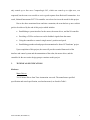
TA115 Motor Driver from Trust Automation was used. The manufacture specified
specification and actual specification, used and measured, are listed in Table 1.
Yellow PUMA (ECE4007L01)
4
Table 1. Trust Automation TA115 Motor Driver Specification [6]
Specified Values
Actual Values
Used
Actual Values
Measured
Supply Voltage (V)
15-48
24
N/A
Digital Signal I/O
TTL Level 1 or 0
Same
N/A
Command Input
±10V
Same
N/A
Current Mode Ratio
(Ao/Vi)
0.2, 0.4,0.6, 0.8
N/A
0.2, 0.4,0.6, 0.8
Voltage Mode Ratio
(Vo/Vi)
20
N/A
14
To minimize the number of power supplies used, the 24V power supply was used to
power both the motor drivers and the brakes for Motors 1, 2 and 3. The actual voltage mode ratio
differs from the manufacturer specifications. With voltage mode ratio of 14, the output voltage is
in the range of ± 140V.
In addition, the motor driver supports opto-isolation, which connects the signal circuit to
the power circuit with optical devices instead of hard wires. Opto-isolation protects the signal
circuit from catastrophic disasters such as lightning strikes by stopping the flow of high voltage
past the motor driver.
Motors
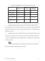
The motors in the arm robot were disassembled from the robot and were tested on the
bench. Table 2 shows the results of the tests performed.
Yellow PUMA (ECE4007L01)
5
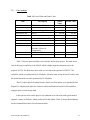
Table 2. Motor specification [7]
Parameter
Motor 1-3
Specified
Motor 1-3 Motor 4-6
Measured Specified
Motor 4-6
Measured
Rated Current (A)
5.3
N/A
1.5
N/A
Rate Voltage (V)
40
Reached
32
Reached
150
N/A
30
N/A
Rate Speed (RPM)
1200
Reached
2350
Reached
Torque Constant
(kg*cm/A)
2.58
N/A
0.973
N/A
Voltage Constant
(V/krpm)
26.5
28.0
10
8.81
Encoder Slots
250
250
250
250
Circular Potentiometer Yes
Yes
Yes
Yes
Rated Power Output
(W)
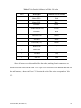
Algorithm for determining the rated parameters could not be found. Parameters are
marked „reached‟ if the specified operating values does not cause sudden increase in
temperature, jerk, or smoke when applied for a few seconds. Certain values were not tested so as
to prevent the motors from damaging. Torque constants were not tested due to lack of proper
equipment.
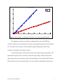
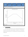
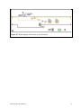
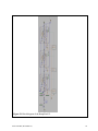
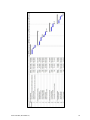
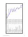
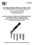
Voltage constants were tested by using the developed software and measuring the RPM
corresponding to an incremental voltage. Matlab was used to approximate the value over the
testing range and Figure 1 shows the generated plot. The Matlab script is posted in Appendix A.
Yellow PUMA (ECE4007L01)
6
Input Voltage vs. Speed
2500
Motor 1
Motor 6
2000
Speed (rpm)
1500
1000
500
0
0
5
10
15
20
25
30
35
Input Voltage (V)
Figure 1. Input Voltage vs. Speed plot for Motors 1 and 6 generated using Matlab.
The quadrature encoders were tested by counting the ticks seen in LabVIEW per
revolution. 1000 ticks were registered per revolution. Assuming the program uses both encoders,
90˚ out of phase from each other, and counts both rising and falling edge, 1000 ticks per
resolution corresponds to 250 slots per encoder.
Circular potentiometer connects both extremes in the output voltage range together. The
potentiometer output resets to zero when it reaches the input voltage, within the range of the
output voltage from zero to the input voltage. The potentiometer is geared down from the motor
shaft, but the gear ratio is not measured since it is not essential in completing the whole project.
Yellow PUMA (ECE4007L01)
7
Controller
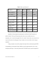
During the project the controller was switched from Rockwell Automation to Nation
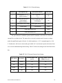
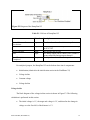
Instruments PCI-7356, to fully support all six axes on the robot. Table 3 shows the I/O pins for
the controller and the required pins for the project.
Table 3. NI PCI-7356 I/O Pins [8]
Supports
Project
Requirements
Encoder
3
3
Encoder A, B, and I
Analog Input
1
1
Potentiometer
Analog Output
1
1
Motor Power
Digital Ports
8
2
Enable/Fault Signal
to/from Motor Driver
Various Switches (Home,
Limit, etc.)
3
0
Currently no Plan for
Installation
Pinout
Use
Other Notes
More information on the robot and its specification is given in Appendix B, to understand
the operation and limitation of the arm robot, when the arm robot is reassembled.
Software
Previously the project was intended to interface the PUMA 560 robot with a Rockwell
Automation motion control system. However, the project‟s motion control system was changed
from Rockwell Automation to National Instruments due to the unavailability of the
CompactLogix L45 in a timely manner. Table 4 displays the proposed versus actual software
specifications.
Yellow PUMA (ECE4007L01)
8
Table 4. Proposed vs. Actual Software Specifications
Proposed
Actual
Motion Controller
Rockwell CompactLogix L45
NI PCI-7356
Programming Language
Rockwell RSLogix5000
NI LabView 8.5
Driver
Built-in
NI Motion 7.6
The software was intended to be able to read and display potentiometer and encoder
signals from the six motors to the user, and to control the analog output voltage signal for the six
motors using the NI PCI-7356 card. The software was also able to find and set the encoder index
position as the motor home position, calculate the speed of rotation, and receive position input
command (in number of revolutions). However, the current software can control only one axis,
and the position command has an offset error of 80°. Table 5 displays a list of the proposed
software objectives and compares it to the actual specifications that were achieved.
Yellow PUMA (ECE4007L01)
9
Table 5. Proposed vs. Actual Software Objectives
Proposed
Actual
Number of Axes Controlled
6
1
Analog Input Reading (POT)
Yes
Yes
Analog Output Control
Yes
Yes
Encoder Reading
Yes
Yes
Speed Calculation
Yes
Yes
Home Calibration
Yes
Yes
0°
~80°
Position Error
4.
DESIGN APPROACH AND DETAILS
4.1
Design Approach
Hardware
Much time was spent on discovering the pinout diagrams for various parts in the robot
and the control system. All the information collected on the pinout diagrams has been
summarized in Appendix C.
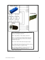
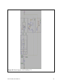
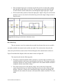
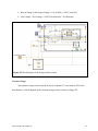
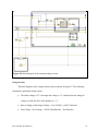
Figure 2 shows the wiring diagram for one axis system with detailed connections. The
wiring diagram shown in Figure 2 and the switch settings in Table C4 of Appendix C allows the
controller to implement the control loop and sends the appropriate command input signals, which
will be discussed further in the software section.
Yellow PUMA (ECE4007L01)
10
Note*: Shared ground for Analog Input, Digital Grounds
for Motion and Digital connectors.
Note**: Only Motors 1-3 have brake, rated at 24V.
Note***: Use digital port for Index Encoder instead of
designated Index Encoder pin. Please refer to Software
section for the reason.
Note: Arrows indicate direction from output to input.
Note: Enable and Fault pins from the motor driver were not
connected in this phase, to simplify wiring.
Note: M1 denotes Motion I/O Connector for Axis 1-4 and
D1 denotes Digital I/O Connector for Axes 1-4.
Figure 2. Sample wiring for one axis.
Yellow PUMA (ECE4007L01)
11
Other Notes
Ensure the brakes on Motors 1-3 release before power is supplied to the motor to
prevent any damages. A „clicking‟ sound will occur when a brake is released.
Index Encoder pulse width is very short. The optimal oscilloscope setting is 1V and
2ms for reading the encoders.
A solid state relay is suggested in order to control the brakes from the software
program. A solid state relay candidate information is listed below:
o Input: Logic
o Output: Up to 60 V DC and up to 3 A
o Part No: Digi-Key CC1126-ND
o Price: $18
Software
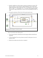
The main LabVIEW VI shown in Appendix D is used as a software interface to control
the analog output port, and read the analog and digital input ports of the motion controller. The
software is connected to Motor Axis 1. Therefore, the parameters used in the software are
specific to Motor 1 only. In addition, the motor has no load mounted on it. The following
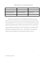
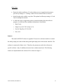
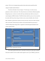
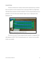
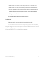
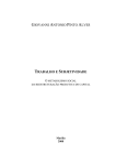
features are implemented in the software GUI as shown in Figure 3.
Yellow PUMA (ECE4007L01)
12
Figure 3. GUI displaying the manual and automated modes along the current encoder position,
potentiometer value, and calculate RPM.
Home Calibration: to set the encoder index position as the home position. This
feature runs automatically when the software is turned on. It runs the motor at the
minimum voltage required to move the motor.
Manual/Auto Switch: to switch between the manual voltage control mode and the
position input command mode. If the switch is set to manual, the motion of the motor
is controlled by turning the voltage control knob. If the switch is set to automatic, the
motion of the motor is controlled based on the input number of desired revolutions.
The maximum voltage produced by the automatic mode is 2 V when running in
current mode with a gain of 0.2. The speed of the running is approximately 780 RPM.
Voltage Control Knob: to control the analog output voltage used to move the motor.
The range of the output voltage is between -10 V to +10 V. The software has to be set
to manual mode to enable the voltage knob.
Input Number of Revolutions: to command the motor to move a certain number of
revolutions. The software has to be set to automatic mode for the input command to
Yellow PUMA (ECE4007L01)
13
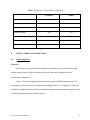
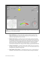
work. The motion is divided into 3 parts: voltage incline (40% of distance), constant
voltage (20% of distance), and voltage decline (40% of distance), as seen in Figure 4.
Figure 4. Motion profile in auto mode (for explanation purposes only, not
measured data).
Encoder Display: to display the current encoder position numerically and
graphically. The numerical display shows the number of encoder ticks. One complete
revolution is equal to 1000 encoder ticks.
POT Display: to display the analog input voltage from the motor‟s potentiometer.
The potentiometer is connected to a 5 V supply.
RPM display: to show the speed of the motor rotation. The speed is calculated based
on ∆s/∆t, where Δt is 0.5 sec and Δs is the encoder ticks difference in 0.5 sec. The
result is than converted into revolutions per minute.
The NI PCI-7356 has a built-in processor to read in the encoder signals. By default, it can
read encoder data at a rate of up to 20MHz [8]. National Instruments also provides the NI Motion
driver that includes LabVIEW VIs needed to read the encoder data from the motion controller
Yellow PUMA (ECE4007L01)
14
memory. The low level communication procedure between the motion controller and the
computer is handled within NI Motion.
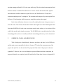
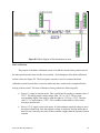
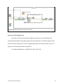
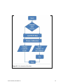
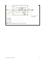
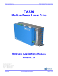
The software flowchart is shown in Figure 5. The first step is to set the necessary
parameters in order to run the motor. The software then moves to the home calibration algorithm.
During this process, it also runs two other while loops simultaneously which is necessary for
encoder display and RPM calculation. The RPM calculation while loop runs at a slower rate than
the encoder while loop, because larger Δt leads to more accurate and stable results. After the
home calibration is performed, the software enters the run mode, which can be either in manual
mode or auto mode. In both modes, the software will run the third while loop necessary to
control the analog output voltage. Refer to Appendix E for block diagrams and details on the
software implementation.
Figure 5. Software implementation flowchart.
The encoder signal from the motor is connected to encoder port on the motion controller.
The motion controller is able to read the encoder signal at a rate of up to 20MHz [9], and stores
Yellow PUMA (ECE4007L01)
15
the values in the memory. The value is obtained in the software using the Read Encoder Data VI.
The encoder index signal is connected to the digital input port of the motion controller. The VI
that is used to read the digital input port is the Read I/O VI. The potentiometer is connected to
the analog input port, and the value is read using the Read ADCs VI. All the VIs are listed in
Table 6.
The home calibration is done by moving the motor at a low speed while constantly
reading the encoder index signal. Once the encoder index signal is found, the encoder value is
reset to zero using the Reset Position VI, and the motor is stopped.
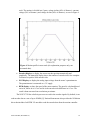
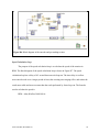
The automatic run mode is done by controlling the output voltage over the period of
encoder distance. The motion consists of 40% voltage incline, 20% constant voltage, 40%
voltage decline as shown in Figure 6. In the first 40% of the distance, starting with the minimum
voltage of 1 V, the voltage is increased at a constant rate over the distance until the output
voltage reaches 2 V. The motor will then move at a constant voltage of 2 V for the next 20% of
the distance and start declining to the minimum voltage required to keep the motor moving at
0.75 V during the last 40% of the position. The implemented motion profile is shown in Figure 7.
Encoder value is used to determine the necessary changes in output voltage. The distance for the
incline, constant, decline voltage, and the rate of change of the output voltage are calculated in
advance based on the given number of revolutions. These values are calculated after the run
button is pressed, but before the motor starts spinning. The automatic run mode algorithm is
written in a separate VI shown in Appendix F. This VI is called from the main software VI.
Yellow PUMA (ECE4007L01)
16
Figure 6. Flowchart of the RampFinal VI.
Figure 7. Implemented motion profile in auto mode (for explanation purposes only, not a
measured data).
4.2
Codes and Standards
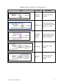
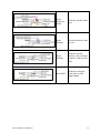
The NI Motion LabVIEW VIs that were used or explored in the development process of
the software are listed in Table 6, based on NI Motion 7.7 and LabView 8.5. The initialization
parameters needed are listed in Table 7. Table 8 shows the ADC conversion value range for the
analog I/O port.
Yellow PUMA (ECE4007L01)
17
Table 6. NI Motion LabVIEW VIs Implemented [10]
Icon
Name
Initialize
Controller
Description
Initializes the motion
controller.
Enables the operating
axes and defines the PID
Enable Axes
and trajectory update
rate.
Yellow PUMA (ECE4007L01)
Configure
Encoder
Polarity
Configures the encoder
Phase A, Phase B, and
Index line polarities.
Load DAC
Controls the output
voltage.
Read I/O
Port
Reads the digital port
for encoder index
reading.
18
Yellow PUMA (ECE4007L01)
Read
Reference
Status
Reads the encoder index
port.
Reset
Position
Resets the encoder value
to zero.
Read
Position
Reads the encoder
position. One revolution
is equal to 1000 encoder
ticks.
Read ADCs
Reads the converted
value from an ADC
input channel.
19
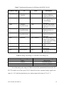
Table 7. Initialization Parameters for NI Motion LabVIEW VIs [10]
Parameter name
VI
Value
Board ID
Initialize
Controller
1
Axis Bitmap
Enable Axes
True
Index
Configure
Encoder Polarity
False
Phase A
Configure
Encoder Polarity
False
Phase B
Configure
Encoder Polarity
False
DAC
Load DAC
DAC Channel 1
ADC
Read ADCs
ADC Channel 1
Axis
Reset Position
Axis 1
Axis
Read Position
Axis 1
Description
Number assigned and
used by NI MAX to
identify the PCI-7356.
The value true means the
axis is enabled. There are
6 Axis Bitmap
parameters.
The value false means
that the encoder index is
active low.
The value false means
that the encoder A is
active low.
The value false means
that the encoder B is
active low.
The analog output port to
control. DAC Channel 1
means control the analog
output channel 1.
The analog input port to
read.
The encoder axis to reset
the position.
The encoder axis to read
the position.
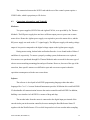
Table 8. Analog Value Range vs. LabVIEW Value Range [10]
Analog Value Range
0 to 5
-5 to +5
0 to 10
-10 to +10 (default)
LabVIEW Value Range
0 to +65,535
-32,768 to +32,767
0 to +65,535
-32,768 to +32,767
Two of the analog value ranges in Table 8 are used for communication between the NI
PCI-7356 and the rest of the system. TA115 Motor Driver takes command voltage signal in the
range of ± 10 V and the potentiometer gives analog output in the range of 0 V to 5 V.
Yellow PUMA (ECE4007L01)
20
The connection between the NI PCI card and the rest of the control system requires a
VHDCI cable, which is proprietary to NI devices.
4.3
Constraints, Alternatives, and Tradeoffs
Hardware
Two power supplies, HP E3630A and Agilent E3634A, were provided by Dr. Thomas
Michaels. The HP power supply does not have sufficient output power to power one or more
motor driver. Hence the Agilent power supply was required to power the motor driver, and the
HP power supply was used as the +5 V signal supply. The HP power supply with analog voltage
output is less precise compared to the digital voltage output on the Agilent power supply.
During motor testing, broken brake and broken Encoder A were found inside of Motor 3
and Motor 4, respectively. To ensure a properly working system, both motors were replaced.
New motors were purchased through Dr. Thomas Michaels and were made for the same type of
robot to ensure matching mounting plate and specifications. However, because of the age of the
arm robot, these specific motors were difficult to spot and were more expensive than the
equivalent counterpart used in the newer arm robots.
Software
The software is developed in LabVIEW programming language rather than other
languages like C or C++ because National Instruments provides NI Motion driver and LabVIEW
VIs that handles all communication between the motion controller and LabVIEW. In addition,
building a user interface in LabVIEW is a matter of drag and drop.
The encoder index from the motor is connected to the digital input port instead of the
encoder index port in the motion controller, because running the Read Reference Status VI
together with the Wait Reference VI in a while loop results in a lower encoder index sampling
Yellow PUMA (ECE4007L01)
21
rate than running the Read I/O VI in the same while loop. The idea behind connecting the Read
Reference Status VI with the Wait Reference VI was to wait for the encoder index signal to
ensure that the controller catches the signal. However, the Wait Reference VI only has a
maximum sampling rate of 1 reading/ms. The situation can be improved by removing the Wait
Reference VI and using the while loop rate to sample the encoder index signal.
In the home calibration, the motor is moved by sending the lowest voltage necessary to
move the motor. The reason is because the encoder index signal is too short. Running the motor
faster than 200 RPM will result in an inconsistent encoder index reading i.e. the software fails to
read all the encoder index signal occurrences. The 200 RPM value is not the border line for the
misreading problem, the exact cutoff speed for the misreading problem is yet to be determined.
5
SCHEDULE, TASKS, AND MILESTONES
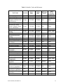
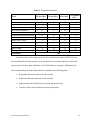
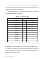
Table 9 displays the scheduled tasks, duration, start dates, end dates, level of difficulty,
and the main person responsible for the task. January 12th marked the commencement of the
project and April 28th was the end date. The proposed Gantt chart of the project is shown in
Appendix G. However, due to several changes in project definition and time constraints, the
proposed schedule was completely modified and the final Gantt chart is shown in Appendix H.
Yellow PUMA (ECE4007L01)
22
Table 9. Schedule, Tasks, and Milestones
Task Name
Project Definition
Meet with Dr. Thomas E.
Michaels to Define Goals
and Objectives
Define Project Scope
Research on Control
System, Software, Motor
Drives, and Motors
Robot Inspection and
Testing
Disassemble Motors
Pin Identification and
Testing
Test Motors Individually
Motor Testing Complete
Order and Parts Delivery
for 2 Motors
Test New Motors
All Motors Working
Rockwell Automation
Controller
Setup Controller
Learn Ladder Logic
Switch to NI Controller
Interface all
Components
Studying Servo
Amplifier
Build Wiring System
Order and Parts Delivery
for 6 Servo Amplifiers
Complete Wiring for
Motor Driver and Motor
Motor Driver Testing
with Motor
Interfaced Controller to
Yellow PUMA (ECE4007L01)
Difficulty
Level
Main
Person
Responsible
Start
Date
Finish
Date
23 days
1/12/2009
2/11/2009
10 days
1/12/2009
1/23/2009
Low
Chao
3 days
1/26/2009
1/28/2009
Low
Tanis
10 days
1/29/2009
2/11/2009
Low
Tanis
32 days
2/12/2009
3/26/2009
7 days
2/12/2009
2/20/2009
High
Chao
2 days
2/23/2009
2/24/2009
Medium
Tanis
7 days
1 day
2/25/2009
3/6/2009
3/5/2009
3/6/2009
Medium
Milestone
Tanis
Tanis
12 days
3/7/2009
3/23/2009
Low
Chao
2 days
1 day
3/24/2009
3/26/2009
3/25/2009
3/26/2009
Medium
Milestone
Chao
Chao
18 days
3/4/2009
3/26/2009
5 days
12 days
1 day
3/4/2009
3/10/2009
3/26/2009
3/9/2009
3/25/2009
3/26/2009
Medium
High
Milestone
Fernandes,
Lie
Fernandes
Fernandes
Lie
23 days
3/9/2009
4/8/2009
3 days
3/9/2009
3/11/2009
Medium
Tanis
5 days
3/12/2009
3/18/2009
Medium
Chao
3 days
3/19/2009
3/23/2009
Low
Chao
1 day
3/26/2009
3/26/2009
Milestone
Chao
3 days
3/27/2009
3/31/2009
Medium
Tanis
5 days
4/1/2009
4/7/2009
Medium
Chao
Duration
Group
Chao, Tanis
Chao, Tanis
23
Motor Driver and Motor
Communication of all
Components Complete
NI Controller Setup
Order and Parts Delivery
for NI PCI-7356
Controller
Setup Controller
Order and Parts Delivery
for Cables and Breakout
Boards
Controller Setup with
Cables and Breakout
Boards
Software
Implementation
Reading Encoders and
Potentiometer
Home Position
Calibration
Position Control
Final Demonstration
6
1 day
4/8/2009
4/8/2009
Milestone
Chao
10 days
3/26/2009
4/8/2009
3 days
3/26/2009
3/30/2009
Low
Lie
2 days
3/31/2009
4/1/2009
Low
Lie
4 days
4/2/2009
4/7/2009
Low
Fernandes
1 day
4/8/2009
4/8/2009
Milestone
Fernandes
14 days
4/9/2009
4/28/2009
4 days
4/9/2009
4/14/2009
High
Lie
5 days
4/16/2009
4/22/2009
High
Fernandes
3 days
1 day
4/23/2009
4/28/2009
4/27/2009
4/28/2009
High
Milestone
Lie
Fernandes
Fernandes,
Lie
Fernandes,
Lie
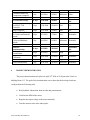
PROJECT DEMONSTRATION
The project demonstration took place on April 28th 2009 at 12:00 pm in the Van Leer
building Room 113. The goal of the demonstration was to show that the developed software
could perform the following tasks.
Read feedback information from encoder and potentiometer.
Calculate the RPM of the motor.
Regulate the output voltage to the motor manually.
Tune the motor to start at the index pulse.
Yellow PUMA (ECE4007L01)
24
Ramp up and down the voltage to the motor to the desired number of revolutions in
forward and reverse mode.
The GUI shown in Figure 3 was divided into two controls, manual and automatic. The
software is to calibrate to the home position and display the encoder position, potentiometer
value, and the calculated RPM regardless of which control mode the software is executed. The
demonstration involved three runs, one in manual mode and two in automatic mode.
During the manual mode, the motor first rotated at 0.75 V (lowest voltage at which
Motor 1 runs) and stopped until the index pulse was found. The voltage was then
regulated manually between -2.00 V to +2.00 V to rotate the motor. Whenever the
motor was in motion, the GUI displayed the current encoder position, the
potentiometer value, and the calculated RPM of the motor numerically and
graphically.
A desired positive number of revolutions was entered for the automated run. Like the
manual mode, the motor first performed the home position calibration. Once the GO
button was clicked, the motor ramped up from 1.00 V to 2.00 V during the first 40%
of the number of revolutions, stayed constant at 2.00 V for the next 20%, and then
ramped down from 2.00 V to 0.75 V during the last 40% of the revolutions.
For the last run, a negative number of desired revolutions was entered. After the home
position calibration and once the GO button was clicked, the motor ramped up from 1.00 V to -2.00 V during the first 40% of the number of revolutions, stayed constant
at -2.00 V for the next 20%, and then ramped down from -2.00 V to -0.75 V during
the last 40% of the revolutions.
7
MARKETING AND COST ANALYSIS
7.1
Marketing Analysis
In 2004, approximately 5% to 15% of the industrial robots in injection molding industry
were six-axis articulated robots [11], leaving a large market for PUMA 560 robots to grow.
However, since the PUMA 560 robot was manufactured back in 1985 [12], it is not equipped
with modern technology such as high speed microprocessor and zero-backlash mechanism such
as the harmonic drive gearing [13]. Compared to the KUKA 5 sixx R850 [14], a modern arm
robot in the same class, the PUMA 560 robot is inferior in many aspects such as speed,
Yellow PUMA (ECE4007L01)
25
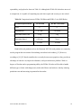
repeatability, and payload as shown in Table 10. Although the PUMA 560 robot does not excel
in comparison, it is capable of completing any task where speed and accuracy are not critical.
Table 10. Comparison between PUMA 500 Robot and KUKA 5 sixx R850 Robot
Technical Specifications
Axes
Repeatability
Maximum Static Load
Maximum Speed
Reach
PUMA 560
KUKA 5 sixx R850
6
6
± 0.1 mm
± 0.03mm
2.5 kg
5 kg
0.508 m/s
7.6 m/s
914 mm
814 mm
Hand-held teach pendants such as the Motoman NXC100 teach pendant are commonly
used to program the movements of articulating arm robots in the industry [15]. However,
according to [16], PC-based controllers have recently become more popular as they provide an
advantage of reduced cost, improved robustness, and open architecture platform. With six
degrees of freedom and re-programming ability, the PUMA 560 robot will be able to handle
different types of tasks with changes only in the end effectors and software, thereby reducing
production cost and increasing its potential in the market.
Yellow PUMA (ECE4007L01)
26
7.2
Cost Analysis
Table 11. Lists of Parts and Labor Costs
Item
Description
Robotic Arm
150 W Motors (1)
30 W Motors (1)
Servo Drives (6)
PLC Controller
PCI Cables (4)
Breakout Boards (4)
Desktop
Miscellaneous
PUMA Robot 560 Series
Unimation Original Parts
Unimation Original Parts
TA115
NI PCI 7356
68 Pin VHDCI M to MD68 M
68 Pin F Vertical Breakout
Dell GX260
Tools, Wires, Connectors,
Switches, Electrical
Components
600 hours x $50 / hour
Labor
Total
Retail
Value
$5,000
$600
$350
$4,200
$2,890
$220
$200
$350
$100
Actual Value
$30,000
$43,910
FREE
$8,460
FREE
$600
$350
$4,200
$2,890
$220
$200
FREE
FREE
Table 11 lists the parts and labor costs needed to work on the project. The total actual
cost for this project ended up to be $8,460, which is higher than the estimated cost in the
proposal, $5,150. The difference in the total cost was due to the purchase of NI PCI 7356
controller, which was sponsored by Dr. Michaels. All other items except for the PCI cables and
the breakout boards were also sponsored by Dr. Michaels.
The PCI cables and the breakout boards, which cost $420 dollars, were purchased from
Daqstuff, a company that replicates connector cables and breakout boards for NI controllers,
using the team‟s senior design fund.
Labor spent to work on the project was estimated to be 600 hours with typical market
engineer‟s salary of $50/hour, which results in $30,000 dollars. Table 12 shows the breakdown
for the estimated labor hours for each team member.
Yellow PUMA (ECE4007L01)
27
Table 12. Estimated Labor Hours
Task
J. Chao (Hr.) J. Tanis (Hr.) D. Lie (Hr.)
Lecture
Reports
Presentation
Website development
Project Research and Definition
Robot Inspection and Testing
Motor Driver Setup
Interface Components
Code Implementation
Final Testing
Total per Person
Total Hours
Class Hours
26
26
27
24
6
6
0
0
Project Hours
25
25
30
30
8
8
28
31
0
0
0
0
150
150
F. Fernandes
(Hr.)
26
24
6
15
26
30
6
0
25
15
0
0
31
8
150
25
20
0
0
35
8
150
600
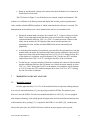
In order to achieve the original goal, which is to interface the whole PUMA 560 robot,
the only additional parts that may have to be purchased are wires and connectors for the entire
wiring system. For these parts, additional cost of $250 dollars is estimated. Additionally, the
team estimated that four hundred labor hours are needed for the following tasks:
Reassemble the motors back to the robot‟s body
Implement kinematic equations on the controller
Implement the control PID loop for position and speed control
Test the overall system and make necessary adjustments
Yellow PUMA (ECE4007L01)
28
8
SUMMARY AND CONCLUSIONS
The initially proposed design goal was to program kinematic equations into the control
system to make the end effectors of the robot move to a specified x, y, and z coordinate with a
specified rotational direction within an error of ± 1 cm and ± 3º, respectively. Due to several
problems that occurred during the semester and time constraints, the goal was not met. However,
the re-proposed goals of the project were successfully achieved.
A system interface is established for the motor, the motor driver, and the NI controller
A GUI is provided for end users to read in feedback signals from the motor
The controller is able to control a single motor‟s position and speed
Established groundwork and prepared documentation for future ECE students‟ project
Appendix I shows all the tasks that were completed during the semester and also provides
a task list for future ECE senior design teams to achieve. Other helpful resources are also made
available on the Yellow PUMA website and can be accessed at the following link.
http://www.ece.gatech.edu/academic/courses/ece4007/09spring/ece4007l01/ws5/index.htm
Yellow PUMA (ECE4007L01)
29
9
REFERENCES
[1]
ATSI. (2008). Articulating Arm Robot [Online]. Available:
http://www.atsi.cc/articulating-arm-robot.htm
[2]
J.M. Pethokoukis. (2004, Mar. 7). Industrial robots are reshaping manufacturing. U.S.
News [Online]. Available:
http://www.usnews.com/usnews/biztech/articles/040315/15eerobots.htm
[3]
ATSI. (2008). Robot Basics [Online]. Available: http://www.atsi.cc/robotbasics.htm
[4]
RobotWorx. (2009). Industrial Arc Welding Robot Application [Online]. Available:
http://www.robots4welding.com/applications.php?app=arc+welding
[5]
Automation.com. (2004). NI Introduces Four PCI Motion Controllers for Manufacturing and
Test Applications [Online]. Available: https://www.automation.com/content/ni-introduces-fourpci-motion-controllers-for-manufacturing-and-test-applications
[6]
Trust Automation, Inc. (April 2000). TA115 Datasheet. [Online PDF] Available:
http://trustautomation.com/Library/pdf/Datasheets/TA115.pdf
[7]
P. Nagy, “The PUMA 560 Industrial Robot: Inside-Out,” Industrial Robot Journal, pp
4.67-4.79, 1988.
[8]
National Instruments (2008). 735x Datasheet. [Online PDF] Available:
http://www.ni.com/pdf/products/us/735x.pdf
[9]
Parasar Kodati. (2004, Aug.). Implementation of an open-architecture for PC-based
control of PUMA 560. NUS, Singapore. [Available]:
http://udel.edu/~parasar/documents/puma_report.pdf
Yellow PUMA (ECE4007L01)
30
[10]
National Instruments (2005, November). NI-Motion VI Help [Microsoft Windows Help
format – Online]. Available:
http://digital.ni.com/manuals.nsf/websearch/BF588B77C64200BE8625711B0050D137
[11]
M. Knights, Six axis robot: where they fit in injection molding, Plastics Technology
[Online Article]. October 1, 2004. Available:
http://goliath.ecnext.com/coms2/summary_0199-1325378_ITM
[12]
Unimation (1985, March). PUMA Mark II Robot 500 Series Equipment Manual for VAL
II and VAL PLUS Operating System.
[13]
A. Lauletta (2006, April), The Basics of Harmonic Drive Gearing, Power Transmission
Engineering, [Magazine]. pp.32.
[14]
KUKA Roboter GmbH, “KR 5 sixx R850,” [Company Website], Available:
http://www.kukarobotics.com/usa/en/products/industrial_robots/small_robots/kr5_sixx_r850/start.htm
[15]
RobotWorx, “Motoman NX100 Teach Pendant,” [Company Website], Available:
http://www.robots.com/motoman.php?controller=nx100
[16]
M. Faroog, “Implementation of a new PC-based Controller for a PUMA robot,” Journal
of Zhejiang University-Science A,” vol. 8, no.12, pp. 1962-1970, Nov. 2007.
[17]
W. Bihr and F. Degrange. (1999). “Interfacing of a Force/Torque sensor on a PUMA 500
robot,” Georgia Institute of Technology, [Online]. Available:
http://helix.gatech.edu/Students/SiouxWill/project.html
Yellow PUMA (ECE4007L01)
31
APPENDIX A – MATLAB CODE
Shown below is the Matlab code used to determine the voltage constant
% v1 and v2 represents the input voltage, where r1 and r2 represent
% the rpm corresponding to the input voltage.
% This data are collected from actual testing.
v1 = 1:35;
v2 = 1:22;
r1 = [0 40 80 120 155 195 220 275 305 340 380 420 460 500 545 585 630
660 690 720 725 760 795 828 867 903 940 976 1011 1053 1087 1124 1161
1197 1239];
r2 = [12 111 225 335 446 560 664 782 887 1001 1117 1238 1345 1462 1573
1687 1809 1926 2044 2155 2272 2382];
% Determine and plot
P1 = polyfit(v1, r1,
new_r1 = polyval(P1,
P2 = polyfit(v2, r2,
new_r2 = polyval(P2,
the 1st-order best-fitting polynomial.
1);
v1);
1);
v2);
% The voltage constant is the inverse of the 1st-order coefficient
% of the polyfit constant.
vc1 = 1000/P1(1)
vc2 = 1000/P2(1)
hold on
plot(v1, r1, 'r+', v2, r2, 'b+', v1, new_r1, 'k', v2, new_r2, 'k')
legend('Motor 1', 'Motor 6')
xlabel('Input Voltage (V)')
ylabel('Speed (rpm)')
title('Input Voltage vs. Speed')
Yellow PUMA (ECE4007L01)
32
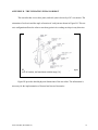
APPENDIX B – THE UNIMATION PUMA 560 ROBOT
The arm robot has six revolute joints, and each joint is driven by a DC servomotor. The
orientation of each axis and the angle of rotation of each joint are shown in Figure B1. This sixaxis configuration allows the robot to reach any point in its working envelope in any direction.
Figure B1. Schematic of Unimation PUMA 560 robot with joint angles,
axis of rotation, and maximum rotation range [16].
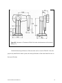
Figure B2 provides detailed physical dimensions of the arm robot. The information is
necessary for the implementation of forward and inverse kinematics.
Yellow PUMA (ECE4007L01)
33
Figure B2. Schematic of Unimation PUMA 560 robot with dimensions of the robot in
inches [17].
Detailed technical specifications of the arm robot can be viewed in Table B1. Since the
project only modifies the control system, the actual performance of the robot should be close to
these specifications.
Yellow PUMA (ECE4007L01)
34
Table B1. Detailed Technical Specifications of the Unimation PUMA 560 Robot
Axes
6 revolute axes
Drive
Electric Brushed DC Servomotors
Repeatability
± 0.1 mm
Maximum Static Load
25 N
Maximum Straight Line Velocity
51 cm/sec
Reach
86.6 cm to the wrist
92.2 cm to the flange
Weight
54.4 kg
Yellow PUMA (ECE4007L01)
35
APPENDIX C – PINOUT DIAGRAM
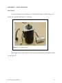
Motor Pinout
Two types of motors are used. Motors 1 to 3 are shown in Figure C1 in the center, and
Motors 4 to 6 are shown in Figure C1 to the right.
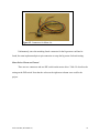
Figure C1. Two types of motor.
The sample pictures of the connector along with the pin numbering are provided in Table
C1 and Table C2.
Yellow PUMA (ECE4007L01)
36
Table C1. Motors 1-3 Pinout Diagram
3
2
1
6
5
4
9
8
7
12 11 10
-
(a)
-
-
Pin Numbers
(b)
Sample Picture
Table C2. Motors 4-6 Pinout Diagram
(a)
Pin Numbers
(b) Sample Picture
Table C3 gives the description of every pin. Note that the pin number applies to all
motors and the small motors have no brake.
Yellow PUMA (ECE4007L01)
37
Table C3. Pin Details for Motors in PUMA 560 robot
Pin #
Description
Motors 4-6 Cable Colors
1
Motor PWR +
Red
2
Motor PWR -
Black
3
Encoder A
Green
4
Encoder PWR (+5V)
Yellow
5
Encoder B
White
6
Encoder GND
Brown
7
Encoder I
Purple
8
Pot PWR (+5V)
Orange
9
Brake PWR
-
10
Brake RET
-
11
Pot RET
Gray
12
Pot o/p
Blue
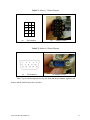
Since all motors were disassembled from the robot, matching female connectors were
needed to test the motors on the bench. Two 15-pin VGA connectors were obtained and made for
the small motors, as shown in Figure C2. Note that the color of the wires corresponds to Table
C3.
Yellow PUMA (ECE4007L01)
38
Figure C2. Connectors for Motor 4-6.
Unfortunately, since the matching female connector for the big motors could not be
found, the team implemented pin-to-pin connection to setup the big motor for bench testing.
Motor Driver Pinout and Control
There are two connectors and one DIP switch on the motor driver. Table C4 describes the
setting on the DIP switch. Note that the values on the right-most column were used for the
project.
Yellow PUMA (ECE4007L01)
39
Table C4. TA115 Switch Setting
Switch S1
Description (Up)
Description (Down)
Value Used
1
User-Supplied +5 V VAUX
(Opto-isolation)
TA115 supplied +5 V
VAUX
Up
2
Power GND and AUX
GND isolated
(Opto-isolation)
Power GND and AUX
GND Shared
Up
3
Fault Signal Active High
Fault Signal Active Low
Up
4
Voltage Mode
Current Mode
Down
5
Gain/Limit Select bit 0
Down
6
Gain/Limit Select bit 1
Down
The opto-isolation is enabled to protect the PCI controller card in the case of an overcurrent flow or a short circuit. The motor driver was run in current mode, because in voltage
mode the amplification gain is fixed at 14, which translates a ± 10 V command signal to ± 140
V. Furthermore, the lowest current mode gain which is 0.2 was chosen to protect the motor from
over-current condition during bench testing. Table C5 shows the setting for the Gain/Limit Select
bits.
Table C5. TA115 Gain and Current Limit Setting
S1-5 (bit 0)
S1-6 (bit 1)
Current Mode Gain
(Ao/Vi)
Voltage Mode Current
Limit ( |Ao,max| )
Down
Down
0.2
2A
Up
Down
0.4
4A
Down
Up
0.6
6A
Up
Up
0.8
8A
Yellow PUMA (ECE4007L01)
40
In current mode the gain/limit select bits control the gain, and in voltage mode the bits
only control the maximum output current. Even with the lowest setting, the maximum output
current is over the rated current for the small motors.
The pinout for the connectors is also necessary to complete the wiring. Table C6 shows
the information about each pin on the connectors.
Table C6. TA115 Motor Driver Pinout
Connector J1
Connector J2
Pin
Description
Pin
Description
1
Command Signal Input +
1
Motor Power +
2
Command Signal Input -
2
Motor Power -
3
Aux GND
3
GND
4
Aux GND
4
GND
5
Not Use
5
VSUPPLY (24V Used)
6
Not Use
-
-
7
/ENABLE
-
-
8
FAULT
-
-
9
Aux GND
-
-
10
VAUX +5V
-
-
With opto-isolation enabled, it is necessary to provide Ground and 5 V to J1-9 and J1-10,
in addition to the 24 V powering the motor driver. The enable pin J1-7 has to be pulled to the
AUX Ground for the motor driver to start. The Enable pin was hard-wired into the Aux GND J19 and the Fault pin J1-8 was not connected. However, it is possible to control these two pins
through the digital ports on the controller.
Yellow PUMA (ECE4007L01)
41
Controller Pinout
The motors and motor drivers cannot be connected to the controller directly, as breakout
boxes are required to secure the connection. There are four 68-pin VHDCI (Very High Density
Cable Interconnect) connectors in the back of the NI PCI-7356. Four 68-pin breakout boxes were
purchased as well as four male-to-male connectors. Figure C3 gives a sample picture of the
breakout box used.
Figure C3. Breakout box for the NI PCI-7356.
Since there are a total of 272 pins coming out from the controller, it is suggested to look
at the datasheet for NI PCI-7356 [5]. Note that the pins for Axis 7 and Axis 8 are not available
for this 6-axis controller.
Yellow PUMA (ECE4007L01)
42
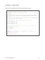
APPENDIX D – FINAL DEMO VI
The FinalDemo.vi is the main VI that needs to be opened using LabVIEW to run the
software. The purpose of the VI is to be able to read the encoder signals and the potentiometer
signal from the motor, control the rotation of the motor, and provide a user interface to the user.
The block diagram of the VI is shown in Figure D1. In addition to LabVIEW and NI Motion VIs,
the FinalDemo.vi also utilizes the developed RampFinal.vi.
Yellow PUMA (ECE4007L01)
43
Figure D1. Block diagram of the FinalDemo VI.
Yellow PUMA (ECE4007L01)
44
For analytical purposes, the FinalDemo.vi can be broken down into 5 components:
Initialization
Home calibration
Run mode loop
Encoder and pot reading loop
Speed calculation loop
Initialization
The parameters needed to properly control the motor is defined in the initialization
section. A block diagram of the initialization section is shown in Figure D2. The initialization
section performs the following tasks:
Initialize the voltage control value to zero
Initialize the motion control
Enable the operating axes
Configure the encoder polarity. All encoders that are used are active low. The
assigned value that indicates active low is the Boolean false.
Yellow PUMA (ECE4007L01)
45
Figure D2. Block diagram of the initialization section.
Home Calibration
The purpose of the home calibration section is to find the encoder index position and set
the index position as the home encoder zero position. A block diagram of the home calibration
section is shown in Figure D3. The flat sequence structure is used to construct the home
calibration section because there is a need to make sure that a certain task is completed before
moving to the next task. The home calibration section performs the following tasks:
Send a 1 V signal to start the motor. This is performed by sending a constant value of
3276.7. The analog output voltage ranges from -10 V to +10 V. However the
corresponding digital value range to send the signal is -32768 to +32767. Thus the
value +1 V is equivalent to +3276.7. This condition is then held for 10 ms before
moving to the next task.
Next, a 0.79 V signal is sent to the motor. It is the minimum required voltage to move
the motor without load. Note that a higher voltage is needed to start the motor due to
static friction. Generally the static friction constant is higher than the dynamic friction
constant.
Yellow PUMA (ECE4007L01)
46
Then, the digital input port is constantly checked for positive encoder index reading.
Note that the encoder index is active low. The parameters sent to the Read I/O Port
VI shows that the encoder index data is sent through the digital input port 1 digit 0.
If the encoder index position is found, the input port 1 digit 0 will go low, the encoder
position is reset to zero, break out from the loop, and set the output voltage to zero to
stop the motor.
Figure D3. Block diagram of the home calibration section.
Run Mode Loop
The case structure is used to construct the run mode loop because there are two possible
run modes available: the manual mode and the auto mode. The case decision is based on the
value sent by the Boolean control switch. The block diagram of the manual mode is shown in
Figure D4 and the block diagram of the auto mode is shown in Figure D5.
The manual mode does the following tasks:
The integer constant 48 and the double constant 11 is used to make sure that the case
condition inside the while loop is true during the first loop run. The integer constant is
compared with the axis value, which is supposed to be one, and the double constant is
compared with the control knob voltage.
The current loop run axis value and the voltage value is then stored in the shift
register for the next loop run. After the first loop run, the axis value will not change
anymore. Therefore, as long as the control knob voltage value does not change, the
condition for the second case structure will remain false, and the Load DAC VI is not
called.
Yellow PUMA (ECE4007L01)
47
Inside the condition true of the second case structure is the third case structure. The
third case structure is used to make sure that the appropriate factor is used in both
negative and positive output voltage case. The -1 V is equivalent to -3276.8 in Load
ADC VI, while +1 V is equivalent to 3276.7. This factor is than multiplied with the
value from the voltage control knob to convert it to the corresponding Load ADC VI
value.
Pressing the stop button will break the while loop and stop the motor.
Figure D4. Block diagram of manual run mode.
The auto run mode does the following tasks:
The go button (labeled as OK button in the block diagram) blinks and disables the
stop button.
Calls the RampFinal VI once the go button is pressed. For this purpose, the event
structure is used.
Enables the stop button once the motion is completed.
Yellow PUMA (ECE4007L01)
48
Figure D5. Block diagram of the auto run mode.
Encoder and Pot Reading Loop
The purpose of the encoder and pot reading loop section is to read and display the
encoder position and the analog input signal from the potentiometer. The block diagram of this
section is shown in Figure D6. In order to graphically display the encoder position in terms of
degrees, the following calculation is performed:
CurrentPositionInDegrees = Mod(EncPos/1000, 1000)*360°
Yellow PUMA (ECE4007L01)
49
Figure D6. Block diagram of the encoder and pot reading section.
Speed Calculation Loop
The purpose of the speed calculation loop is to calculate the speed of the rotation in
RPM. The block diagram of the speed calculation loop is shown in Figure D7. The speed
calculation loop has a delay of 0.5 second between each loop run. The time delay is to allow
more encoder ticks over a longer period of time, thus creating an averaging effect, and makes the
result more stable and more accurate than the result performed by faster loop run. The formula
used to calculate the speed is:
RPM = Abs(ΔEncPos/1000*60)/Δt
Yellow PUMA (ECE4007L01)
50
Figure D7. Block diagram of the motor speed calculation.
Yellow PUMA (ECE4007L01)
51
APPENDIX E – USER MANUAL
The user manual is made available to guide the user in running the software application
with ease.
In order to use the software, the following items will be needed:
Windows based PC capable of running NI LabVIEW
NI PCI-7356 Motion Controller
NI LabVIEW 8.5 software
NI Motion 7.6 software driver
FinalDemo VI
RampFinal VI
The current developed software is not a standalone application. Therefore the correct
version of NI LabVIEW, NI Motion, and the VIs listed above will be needed to run the software
application.
Follow the steps below to run the software:
Open the FinalDemo.vi using NI LabVIEW.
Switch between the manual (manual voltage control using the knob) and auto (voltage
is controlled automatically based on the input number of revolutions) mode.
If the switch is set to auto, put in the desired number of revolutions in the numeric
control. The numeric control accepts decimal input.
Click the start button.
The home calibration algorithm will run automatically, wait until the home
calibration is completed. The motor will stop spinning and the encoder position will
be reset. This will be the indication that the home calibration is complete.
Yellow PUMA (ECE4007L01)
52
If the switch is set to manual, use the voltage control knob to control the motor.
If the switch is set to auto press the blinking go button to start position command.
Press the stop button to close the software. In auto mode, user has to wait until the
motion is completed before pressing the stop button. The stop button is disabled
during the auto mode motion.
The flowchart of the user interaction is shown in Figure E1.
Troubleshooting
Q: Why does not the motor move during the home calibration mode?
A: It means that the motor doesn’t have enough voltage supply. To solve this problem,
change the voltage value in the second sequence in the home calibration section to a value that
is higher than 2600.26 (0.79 V) or wait until the mot warms up.
Yellow PUMA (ECE4007L01)
53
Figure E1. User interaction flowchart.
Yellow PUMA (ECE4007L01)
54
APPENDIX F – RAMP FINAL VI
The RampFinal.vi is called by the main VI in the run auto mode section. The purpose of
the RampFinal VI is to automatically create the motion profile as seen in Figure 7, which
consists voltage incline (40% of the distance), constant voltage (20% of the distance), and
voltage decline (40% of the distance). The block diagram of the RampFinal VI is shown in
Figure F1. The diagram of the RampFinal input and output ports are shown in Figure F2. The
input and output ports of the VI are listed in Table F1.
Yellow PUMA (ECE4007L01)
55
Figure F1. Block diagram of the RampFinal VI.
Yellow PUMA (ECE4007L01)
56
Figure F2. Diagram of the RampFinal VI
Table F1. I/O Ports of RampFinal VI
Name
Direction Description
Desired Numer of
Revolutions
Board ID
Input
The desired number of revolutions to perform.
Input
Axis or Encoder
DAC
Input
Input
No of Revolutions
Completed
Output
Number assigned and used by NI MAX to identify
the PCI-7356.
The encoder axis to read.
The analog output port to control. DAC Channel 1
means control the analog output channel 1.
The elapsed number of revolution performed.
For analytical purpose, the RampFinal VI can be broken down into 4 components:
Initialization (identical to the initialization section in the FinalDemo VI)
Voltage incline
Constant voltage
Voltage decline
Voltage incline
The block diagram of the voltage incline section is shown in Figure F3. The following
calculation is performed in this section:
The initial voltage is 1 V, the target end voltage is 2 V, and therefore the change in
voltage over the first 40% of the distance is 1 V.
Yellow PUMA (ECE4007L01)
57
Rate of change of the Output Voltage = 1/(0.4*1000) = 0.0025 Volts/tick
NewVoltage = PrevVoltage + 0.0025*(NewEncoder – PrevEncoder)
Figure F3. Block diagram of the voltage incline section.
Constant Voltage
The constant voltage section runs the motor at a constant 2 V over the next 20% of the
total distance. A block diagram of the constant voltage section is shown in Figure F4.
Yellow PUMA (ECE4007L01)
58
Figure F4. Block diagram of the constant voltage section.
Voltage Decline
The block diagram of the voltage incline section is shown in Figure F5. The following
calculation is performed in this section:
The initial voltage is 2 V, the target end voltage is 1 V, and therefore the change in
voltage over the last 40% of the distance is -1 V.
Rate of change of the Output Voltage = 1/(0.4*1000) = 0.0025 Volts/tick
NewVoltage = PrevVoltage – 0.0025*(NewEncoder – PrevEncoder)
Yellow PUMA (ECE4007L01)
59
Figure F5. Block diagram of the voltage decline section.
Yellow PUMA (ECE4007L01)
60
APPENDIX G – PROPOSED PROJECT GANTT CHART
See next page for project Gantt chart.
Yellow PUMA (ECE4007L01)
61
Yellow PUMA (ECE4007L01)
62
APPENDIX H – FINAL PROJECT GANTT CHART
See next page for project Gantt chart.
Yellow PUMA (ECE4007L01)
63
Yellow PUMA (ECE4007L01)
64
APPENDIX I – TASK LIST
Below is the list of tasks that were completed by the team during the semester.
Define and discuss design goals with Dr. Michaels
Research and gather technical specifications about the PUMA 560 and motors
Determine pin layout for the main wire harness connector ELCO 8016
Check existence of limit switches
Remove all motors from the robot
Test brake release for the three big motors
Test Encoders A, B, and Index for all six motors
Test potentiometer output for all six motors
Replace and test the two broken motors
Learn to use the purchased motor driver
Build wiring system to connect the motor driver and motor
Replace Rockwell CompactLogix L43 controller with NI PCI-7356 controller
Interface the NI controller with the motor and motor driver
Develop a GUI to control the motor
Yellow PUMA (ECE4007L01)
65
Control the motor using command analog voltage
Read encoder and potentiometer feedback signals
Calculate RPM of the motor in motion
Control the position and speed of the motor
Below is the list of tasks that need to be achieved by future senior design teams.
Implement the control PID loop for position and speed control
Add limit switches algorithm within the software program
Wire and interface all 6 motors
Program to control all 6 axes
Install the 6 motors into the robot
Determine the actual limit switch values
Program forward and inverse kinematic equations
Test overall system and make necessary adjustments
Yellow PUMA (ECE4007L01)
66