1
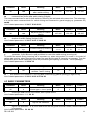
Examples of frame configuration
1.3 MODULE FEATURES
NUDV Basic Module
The 1145 basic module is supplied in two variants, with two buttons 1145/2 and one button 1145/1.
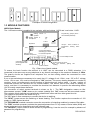
Setting volume of
speaker
Programming jumper (short –
don’t needed password)
Setting volume of
microphone
1145/4
Expansion
Jumper – short is switch on
temperature heating basic
board
TRH
Setting level for
activation microphone
Connect flat cable for
extending up to 64 buttons or
for connect keyboard
Connect telephone line
Connecting to earth –
protect against static
electricity
Contact 1 switch
Contact 2 switch
Power supply 12V ac/dc
For two switches, lighting
heating
and
Fig. 1 Rear view of basic module
To ensure the basic function the terminal “a b LINE” can be connected to a PABX extension. It is
connected in the same way as any telephone to any branch exchange to the maximum distance of 300m.
The guard’s circuits are supplied from telephone line, so that nothing should be connected for voice
communication.
If one or two switches are necessary to be used, the A.C. voltage of min. 10Vst - max. 15V or D.C. voltage
of min. 12V to max. 18V must be energized to "12V" terminal. This source loading depends on number of
modules, since it simultaneously serves feeding of lighting through visiting cards – at max. number of
connected modules the demand will not exceed 300mA. This source can be also used for feeding of
lock(s), and then it is necessary to consider the electrical lock demand. In practice the alternating feeder
12V/1A mostly meets these demands.
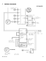
The connection of switch contact terminals is shown on fig. 1. The "NO" designation means an idledisconnected contact, "COM" means a pin contact (middle) and "NC" means an idle-connected contact.
The contacts of both switches are galvanically isolated each other and from other guard circuits.
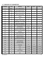
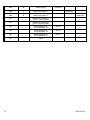
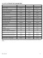
The variants of connection are shown on fig. 2.
The "G" Faston 2.8mm necessary to connect the device to earthing.
The "HEAT" jumper serves the switching of board heating. This function requires the connection of 12V
supply on "12V" marked terminal.
The "EXPANSION" marked connector serves the connection of extending modules by means of flat cable.
The "PRG" marked connector provides the guard adjustment from PC by means of serial cable (KAB) and
serves to the service for diagnostics and new software load.
The "SERVICE" jumper serves to direct access to programming. It can be used, for example by absence of
password for programming.
4
DS1145-019