1
CENTROID
M-SERIES
Operator's Manual
Version 8.22
Rev. 030826
U.S. Patent #6490500
© 2004 Centroid Corp. Howard, PA 16841
™
CNC Control Information Sheet
Fill out the following and fax back to Centroid Tech support 814-353-9265. Date: _________
Company name: _________________________ Your name: ____________________________
Address: ______________________________ City: _________________ State:____ Zip: ________
Phone #: ________________ Fax #: __________________
Control Serial Number K_________ Software Version: _______ Approx. purchase date: __________
Dealer: ____________________________ Machine Brand: __________________________
Machine type (check below)
Knee Mill
Machining Center
Bed Mill
Lathe
Router
Other
Please indicate the messages (word for word) in the message window:
Message Window Example
Error Messages
1
2
3
4
5
Describe the symptoms. What does the system do (or not do)?
System Voltages (requires an AC/DC voltmeter)
Source L1/L2________VAC
Source L1/L3________ VAC
Source L2/L3________ VAC
Drive Voltage ______ VDC Measured at terminal 9 (GND) and 10 (+Vm) on the servo drive (E-Stop
Released).
Phase Converter Yes ____ No ____
Control Parameters
Please fill in the parameter tables below. To get to the parameter screens:
1. Go to the Main screen of CNC7 software (this is the screen that appears when your system is first turned on).
2. Press <F1> to enter the Setup screen.
3. Press <F3> to enter the Configuration screen.
4. Type "137" in the window which asks for the password. Press <ENTER> to accept this.
5. Press <F2> Machine for Jog and Motor parameters.
Jog Parameters
Slow Jog
(inches/minute)
Axis
Fast Jog
(inches/minute)
Max Rate
(inches/minute)
Dead Start
(inches/minute)
Delta Vmax
(inches/minute)
X
Y
Z
4th
5th
Motor Parameters
Axis
Label
Motor
revs/inch
Encoder
counts/rev
Limit
Lash
-
Home
+
+
Direction
Reversed
Ka
Accel.
-
Travel
1
2
3
4
5
PID parameters: Press ESC at the motor/jog parameters screen. Then press F4 PID
Axis
Kp
Ki
Kd
Limit
Kg
Kv1
Max. Vel.
1
2
3
4
5
To obtain the control configuration info, press ESC at the PID screen, then press F1 Control:
DRO display units:_______
Machine units:__________
Max spindle (high range):__________
Machine home at powerup:________
Console type (Jog Panel Type):__________
Jog panel required:____________
Screen blank delay:___________
RS232 Drive & Directory: ________________
Parameters: To obtain following parameter info, press ESC at the Control Configuration screen, and then press F3
Params:
Param
#
21
22
Value
Param
#
23
24
Value
Param
#
29
30
Value
Param
#
40
41
Value
Param
#
56
57
Value
Param
#
58
59
Value
TABLE OF CONTENTS
CHAPTER 1 - Introduction
Window Description
Conventions
Machine Home
Keyboard Operation
1-1
1-3
1-4
1-5
CHAPTER 2 - CNC7 Main Screen
Option Descriptions
Canceling and Resuming Jobs
Canceling a Job in Progress
Resuming a Canceled Job
M-Series CNC G-Code Editor Description
2-1
2-6
2-7
2-7
2-8
CHAPTER 3 - Part Setup (F1 from Setup)
Operation Description
3-2
Part Setup Examples
3-4
Work Coordinate Systems Configuration 3-5
Coordinate Systems Rotation
3-7
CHAPTER 4 - Tool Setup (F2 from Setup)
Offset Library
4-1
Automatic Tool Measurement
4-3
Setting up Tool Height Offsets
4-3
Tool Library
4-4
CHAPTER 5 - Power Feed (F4 from Setup)
CHAPTER 6 - The Utility Menu
F1 - Format
F2 – Update, F3 - Backup
F4 - Restore
F5 - File Ops, F6 - PLC Diag.
F7 – Report, F8 – Options, F9 – Log
6-1
6-2
6-3
6-4
6-4
CHAPTER 9 - Engraving
Quick Start Engraving Software Tutorial
CHAPTER 10 - Intercon Software
Intercon Main Screen
Insert Operation
Graphics
Math Help
Intercon Tutorial #1
Intercon Tutorial #2
Grid Digitize
Radial Digitize
Contour Digitize
CHAPTER 8 - Probing
Part Setup with Probing
Calibrating the Probe Tip Diameter
Probing Cycles
Probe Parameters
7-2
7-6
7-10
8-1
8-2
8-2
8-6
10-1
10-8
10-42
10-44
10-52
10-58
CHAPTER 11 - CNC Program Codes
Miscellaneous CNC Program Symbols
11-1
CHAPTER 12 - G-codes
G-Code Quick Reference
12-1
CHAPTER 13 - M functions
Macro M functions
13-1
CHAPTER 14 - Operator Panels
M-400 Operator Panel / M-39 Jog Pendant141
Keyboard Jog Panel
14-6
CHAPTER 15 – Configuration
Password
Control Configuration
Machine Configuration
Machine Parameters
PID Configuration
Handwheel Configuration
CHAPTER 16 - CNC7 Messages
CHAPTER 7 – Digitize (F9 from Main Menu)
9-1
15-1
15-2
15-5
15-8
15-26
15-28
CHAPTER 1
Introduction
Window Description
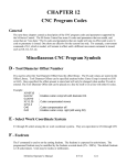
The CNC7 display screen is separated into five areas called windows. A sample screen is shown below for
reference. The five windows are the DRO display window, the status window, the message window, the options
window, and the user window. The information that each window displays is described in detail in the following
sections.
DRO Display Window
Status
Window
Message
Window
User
Window
Options
Window
DRO display
The DRO display contains the digital read out of the current position of the tool. The display is configurable for
number of axes and desired display units of measure (see Chapter 15). The bars under each axis are the load meters
and represent the amount of power being supplied to the drive for that axis. The display of axis load meters is
configured by machine parameter 143 – see Chapter 15 for specific information. See also “Hot Keys” later in this
chapter.
Distance to Go DRO
The distance to go DRO is located below the main DRO. This display shows the distance to go to complete the
current movement. The display of distance to go is controlled by parameter 143. See Chapter 15 for details. See
also “Hot Keys” later in this chapter.
M-Series Operator’s Manual
3/2/04
1-1
Status window
The first line in the status window contains the name of the currently loaded job file. Below the job name are the
Tool Number, Program Number, Feedrate Override, Spindle Speed, and Feed Hold indicators. The Feedrate
Override indicator displays the current override percentage set on the Jog Panel. The Feedrate label will turn RED
if the rapid override is turn off. If your machine is equipped with a variable frequency spindle drive (inverter), the
Spindle indicator will display the current spindle speed. The Feed Hold indicator displays the current status
(on/off) of FEED HOLD. See Chapter 14 for descriptions of the Feed Hold Button, Feedrate Override Knob, and
Spindle controls. For a description of the Program Number see G65 in Chapter 12 or M98 in Chapter 13.
The Part Cnt and Elapsed Time indicators appear when CYCLE START is pressed while a job is running. The Part
Count indicator displays the number of times the currently loaded job has been run. They count increments by one
after the completion of a run. If a job is canceled prematurely, the part count will not be incremented. The Part #
counter shows the how many parts have been run, with an up/down arrow displayed to indicate the counting
direction. See the run menu for more information on the Part Cnt and Part # setting.
The Part Time indicator displays how much time has passed since the CYCLE START button was pressed. The
indicator will help you to determine how long it takes to mill a particular part. The timer will not stop until the job
is canceled. It will continue to count for optional stops, tool changes, FEED HOLD, etc.
Message window
The message window is divided into a message section and a prompt section. The prompt section of the window is
the lowest text line in the window and will display prompts to the user. For example, the prompt 'Press CYCLE
START to start job' is displayed on the prompt line after power-up.
The message section is the top four text lines of the message window. This section will display warnings, errors, or
status messages. The newest messages always appear on the lowest of the four lines. Old messages are shifted up
until they disappear off the top of the message window. See Chapter 17 for a description of the CNC7 error and
status messages.
Options window
Options are selected by pressing the function key indicated in the box. For example, on the main screen, pressing
the function key <F5> selects the CAM option.
User window
The information contained in this window is dependent upon on the operation the user is performing on the control.
If no action is being taken, the window is empty.
For instance, when the CYCLE START button is pressed and a job is processed correctly, up to 11 lines of G codes
will be displayed in this window for the user to observe during the Run of the part. All of the part zeros, the tool
library setup, and the Digitizing/Probing information are entered in by the user in this window.
M-Series Operator’s Manual
3/2/04
1-2
Conventions
*Keystrokes are represented by enclosing the capitalized name of the key in "less than" and "greater than" symbols.
For example, the A key is written as <A> and the enter key is written as <ENTER>. The "Escape" key is written as
<ESC>. Key combinations such as <ALT- D> mean that you should press and hold <ALT> then press <D>.
*All data entry screens in the M-Series Control use <F10> to save changes.
*Any menu in the M-Series Control can be exited by pressing <ESC>. This will take you back to the previous
menu. This also usually discards any changes you have made in that menu.
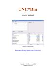
*All program examples and software use the standard Cartesian coordinate system (see the figure below). If you
are facing the mill, the X-axis is defined positive to your right; the Y-axis is defined positive to the mill; and the Zaxis is defined positive upward, perpendicular to the XY plane.
*The direction of motion is defined by the CUTTER motion, not the TABLE motion.
*CW stands for clockwise, and CCW stands for counterclockwise.
M-Series Operator’s Manual
3/2/04
1-3
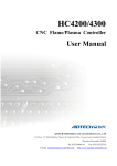
Machine Home
When the M-Series control is first started, the Main screen will appear as below.
Before you can run any jobs, you must set the machine home position. If your machine has home/limit switches,
reference marks or safe hard stops, the control can automatically home itself. If your machine has reference marks,
jog the machine until the reference marks are lined up, (see below), before you press CYCLE START to begin the
automatic homing sequence. The control will execute the G-codes in a file called CNC7.HOM in the C:\CNC7
directory. By default, this file contains commands to home Z in the plus direction, then X in the minus and Y in the
plus direction.
Typical Reference Marks
If your machine does not have home/limit switches or safe hard stops, the following message will appear instead.
In this case you must move the machine to its home position yourself, using either the jog keys or the handwheels.
Once all axes are at their home positions, press CYCLE START to set machine home.
M-Series Operator’s Manual
3/2/04
1-4
Keyboard Operation
A computer style keyboard is supplied with most systems. This keyboard can be used as a jog panel. See Chapter
14, “Operator Panels” for more information. The keyboard jog panel has many “hot keys”. Hot keys are keys that
can be used at almost any time, with few exceptions. (Some menus may prohibit their use.) CNC7 has many other
hot keys in addition to the jog panel hot keys. The hot keys are listed below.
Hot Keys
Hot Key
<ALT A>
<ALT B>
<ALT C>
<ALT D>
<CTRL D>
<ALT E>
<ALT F>
<ALT H>
<ALT I>
<ALT J>
<ALT K>
<ALT M>
<ALT O>
<ALT P>
<CTRL_P>
<ALT Q>
<ALT R>
<ALT S>
<ALT T>
<ALT V>
<ALT W>
<ALT +> <ALT ->
<ALT 1> - <ALT 0>
<CTRL F1> - <CTRL F12>
Action
Spindle auto/manual*
Screen blanker on
Flood coolant on/off*
Switch between current position and machine position
Switch DRO between position and distance to go
Mist coolant on/off*
Displays available system memory
Feed hold on/off*
PLC diagnostics
Enables keyboard jogging*
Displays current ATC tool bin location
MDI
Tool check*
Live PID display
Clear max and min error display
Spindle on/off counter-clockwise*
Spindle on/off clockwise*
Cycle start
Displays current motor temperature estimates
Displays current software version #
MPG on/off*
Selects next WCS, cycles through WCS 1-18**
Selects WCS 1 – WCS 10**
Executes Aux function 1 – 12*
Notes:
* This is a keyboard jog panel function. See Chapter 14 for details.
** Not available during jobs, in jog panel or while handwheels are engaged.
M-Series Operator’s Manual
3/2/04
1-5
Mill M and G Codes
This is a summary list of M and G codes. See Chapters 12 – 13 for more information.
M00
M01
M02
M03
M04
M05
M06
M07
M08
M09
M10
M11
M15
M16
M18
M19
M20
M21
M22
M23
M24
M25
M26
M39
M50
M51
M80
M81
M91
M92
M93
M94
M95
M98
M99
M100
M101
M102
M103
M104
M105
M106
M107
M108
M109
M115
M116
M120
M121
M122
M123
M125
M126
Stop for operator
Optional Stop for operator
Restart Program
Spindle on CW
Spindle on CCW
Spindle off
Start Tool Change
Mist Coolant on
Flood Coolant on
Coolant off
Clamp on
Clamp off
Unclamp tool, air on
Unclamp tool, air off
Home tool changer
Orient spindle
Pick up tool
Move head up
Move head to ATC level
Rotate carousel
Start tool put back
Move to Z home
Set axis home
Air drill
Index tool plus
Index tool minus
Carousel in
Carousel out
Move to minus home
Move to plus home
Release motor power
Turn on input X
Turn off input X
Call subprogram
Return from subprogram
Wait for input to open
Wait for input to close
Restart program
Programmed action timer
Cancel programmed action timer
Move minus to switch
Move plus to switch
Output BCD tool number
Enable override controls
Disable override controls
Protected probing move
Protected probing move
Open data file (overwrite existing file)
Open data file (append to existing file)
Record position(s) and/or comment in data field
Record value and/or comment in data field
Protected probing move
Protected probing move
M-Series Operator’s Manual
G00
G01
G02
G03
G04
G09
G10
G17
G18
G19
G20
G21
G28
G29
G30
G40
G41
G42
G43
G44
G49
G50
G51
G52
G53
G54
G55
G56
G57
G58
G59
G61
G64
G65
G68
G69
G73
G74
G80
G81
G82
G83
G84
G85
G89
G90
G91
G92
G98
G99
G117
G118
G119
Rapid Positioning
Linear Interpolation
Circular or Helical Interpolation CW
Circular or Helical Interpolation CCW
Dwell
Exact Stop
Parameter Setting
Circular Interpolation Plane Selection XY
Circular Interpolation Plane Selection ZX
Circular Interpolation Plane Selection YZ
Select Inch Units
Select Metric Units
Return to Reference Point
Return from Reference Point
Return to Secondary Reference Point
Cutter Compensation Cancel
Cutter Compensation Left
Cutter Compensation Right
Tool Length Compensation (+)
Tool Length Compensation (-)
Tool Length Compensation Cancel
Scaling/Mirroring Off (Optional)
Scaling/Mirroring On (Optional)
Offset Local Coordinate System Origin
Rapid Position in Machine Coordinates
Select Work Coordinate System #1
Select Work Coordinate System #2
Select Work Coordinate System #3
Select Work Coordinate System #4
Select Work Coordinate System #5
Select Work Coordinate System #6
Exact Stop Mode
Cutting Mode
Call Macro
Rotate
Cancel Rotate
High Speed Peck Drilling
Counter Tapping
Canned Cycle Cancel
Drilling and Spot Drilling
Drill with Dwell
Deep Hole Drilling
Tapping
Boring
Boring with Dwell
Absolute Positioning Mode
Incremental positioning Mode
Set Absolute position
Initial Point Return
R Point Return
Rotation of Plane Selection XY
Rotation of Plane Selection ZX
Rotation of Plane Selection YZ
3/2/04
1-6
CHAPTER 2
CNC7 Main Screen
Option Descriptions
F1 – Setup
This will bring up the Setup menu as shown below.
F1 - Part
This key displays the Part Setup menus which are explained in Chapter 3.
F2 - Tool
This key displays the Tool Setup menus which are explained in Chapter 4.
F3 - Config
This key displays the Configuration menu which is explained in Chapter 15.
F4 - Feed
This key displays the Feed menu which is discussed in Chapter 5.
F5 – 3rd Axis Toggle
This key will only be displayed if Machine parameter 130 is set. See Chapter 15 for the various settings.
F6 – 4th Axis Toggle
This key will only be displayed if Machine parameter 131 is set. See Chapter 15 for the various settings.
F7 – ATC
This key will only be displayed if Machine parameter 6 is set to 1.0. It has the same effect as the <F7> ATC key in
the Tool menus, which is to prompt for a tool number and then perform the actions required for an automatic tool
change cycle.
M-Series Operator’s Manual
3/2/04
2-1
F2 – Load Job
This option allows you to specify the file name of the CNC program that you want to run next. On the Load Job
screen, the available keys are:
<F1>
<F2>
<F3>
<F10>
<Page Up>
<Page Down>
<END>
<HOME>
Arrow Keys
change to the Floppy drive (A:\ directory)
change to the Hard Drive (C:\CNC7\NCFILES directory)
change to an attached computer's drive via RS232 port or network
connection
load the selected file
move the cursor back one page. (A page is 32 files)
move the cursor forward one page.
select the last file in the list.
select the first file in the list.
move the cursor in the selected direction
When the Load Job screen is first displayed, the initial list of files will come from the controller's hard drive. Press
<F1> to switch to the controller's floppy drive, or press <F3> to switch to the drive of a computer attached via an
Remote null modem cable. Press <F2> to switch back to the Controller's hard drive. You can use the arrow keys to
move the cursor to the file you want to load. Once the job file name you wish to load is displayed on the "Job to
load" line, press <F10>.
If you wish to use the Remote feature with an RS-232 null modem cable, you should run the INTERSVR program
(supplied with IBM DOS) on the attached computer. If you wish to use the feature with a network connection the
server should be a suitable DOS compatible LAN server. See Remote Drive and Directory in Chapter 6 if you need
to set up a default drive and directory for the Remote feature.
Subdirectories are shown at the end of the list with square brackets, "[" and "]", around the name. If the current
directory is not the root directory, a parent directory reference is shown as the last item of the list, signified by an
up arrow next to the name.
Advanced users:
The "Job to load" line can perform functions similar to the DOS commands DIR and CD. See the examples below:
If you type:
*.CNC
F*. *
..
A:
\
C:\ICN
A:\G*.CNC
TEST?.CNC
M-Series Operator’s Manual
The screen will
display all files in the current directory that have a
.CNC extension
display all files in the current directory that begin with
F
move up one directory and display all files located in
that directory
change to the last selected directory on the A: floppy
drive and display all files located in that directory
change to the root directory of the current drive and
display all the files located in that directory
change to the C:\ICN directory and display all the
files located in that directory
change to the A: floppy drive root directory and
display all files beginning with G that have a CNC
extension
display all files beginning with TEST that have one
more character (TESTA, TEST1, etc.) and have the
C C
3/2/04
2-2
CNC extension
Using this ability is similar to using DIR and CD in DOS but leaving off the DIR or CD. If you can only remember
part of the file name or it is located in another directory, these commands make it easier to locate. (See the DIR and
CD commands in your PC-DOS manual for further information).
Do NOT load non G-code files and attempt to run or edit them. This can cause serious damage to the
machine and controller, destroy the file, or cause personal injury.
F3 - MDI
Press <F3> to directly enter M and G-codes one block at a time. Enter one line of M or G-codes and then press
<CYCLE START>. The controller will execute the command. It will then prompt you for another line. When you
are finished entering commands, press <ESC>. The Rapid Override function key <F9> appears while in MDI
mode (see below).
Examples:
Block? G92X0Y0
Block? M26
; Set the current XY position to 0,0
; Set the current Z position as Z home
All of the functions of Part Setup and Power Feed can be performed in MDI mode by typing the
appropriate G and M-codes.
F4 - Run
Press <F4> to change the way your part program will run. An example screen appears below:
F1 - Resume Job
The Resume Job feature allows you to resume a previously canceled job at or near the point of interruption. See the
section in this chapter titled "Canceling and Resuming Jobs" for a further detailed explanation.
F2 - Search
Invoking this option will bring you to the “Search and Run” menu. This menu will allow you to specify the
program line, block number, or tool number at which execution of a program is to begin. Program lines are
numbered from the top of the file down with the first line numbered 1. To enter a block number place an "N" in
front of the number. To enter a tool number place a "T" in front of the number. Pressing CYCLE START from
here would start the program at the point you specified.
M-Series Operator’s Manual
3/2/04
2-3
An extra option unique to the “Search and Run” screen is the <F1> “Do Last Tool Change” function. This key
toggles the tool change option as shown on screen. A "YES" tells the control to perform a tool change so that the
tool specified for the line or block has the tool indicated in the program. A "NO" uses the currently loaded tool,
regardless of what tool is specified for the line or block being searched.
F3 – Repeat On/Off
This key toggles the repeat feature for part counting. When part counting is in effect and Repeat is on, the job will
be automatically run again until the specified number of parts have been run. The On or Off label indicates the
state to which the repeat feature will toggle to when pressed. It does not indicate the current state. The current
state is indicated in the user window above.
The Part Count: prompt is used to set the Part count. Positive values set the part counter to count up and negative
values configure the part count to count down. For example, if 10 is entered in the Part Count prompt, the Part Cnt
in the status window changes to 10 and the Part # changes to 0 with an upward arrow indicator. When a job is run
and then completes, the Part # will increment to 1. If repeat is on, the job will automatically start again and keep
running until the Part # has reached the Part Cnt. If a –10 is entered in the Part Count prompt, the Part Cnt in the
status window changes to 10 and the Part # changes to 10 with a downward arrow indicator. When a job
completes, the Part # will decremented to 9. If repeat is on, the job will automatically start again and keep running
until the Part # has reached 0.
F4 - /Skips On/Off
This function toggles the block skip feature. When block skipping is on, G-code lines that start with a forward
slash character ‘/’ are skipped, i.e., they are not processed. The On or Off label indicates the state to which the
/Skips feature will toggle to when pressed. It does not indicate the current state. The current state is indicated in
the user window above.
F5 - Block Mode
Turns single block mode on and off. This is similar to pressing AUTO/BLOCK. If single block mode is on, CNC7
will stop after each block in your part program and wait for you to press CYCLE START. The current state is
indicated in the user window above.
F6 - Optional Stops
Turns optional stops on and off. If optional stops are on, any M1 codes that appear in your program will cause a
wait for CYCLE START (just like M0). If optional stops are off, M1 codes will be ignored. The current state is
indicated in the user window above.
F8 - Graph
Graphs the part. For more information, see the "<F8> - Graph" as described later in this chapter. If this feature is
invoked from the Run and Search screen or the Resume Job screen, then the graphics will show exactly where the
searched line or block begins. Dotted lines indicate the portion of the part that is skipped. Solid lines indicate the
portion of the part that will be machined.
F9 – Rapid On/Off
This function key toggles Rapid Override. The On or Off label indicates the state to which the Rapid Override
feature will toggle to when pressed. It does not indicate the current state. It has the same effect as the Rapid Over
key discussed in Chapter 14.
F10 – RTG On/Off
This function key toggles the Run-Time Graphics option. If the option is turned on, Run-Time Graphics
automatically starts when the CYCLE START button is pressed. This option must be turned on for Run-Time
Graphics to be used. If the option is turned off, Run-Time Graphics cannot be started while a job is running.
M-Series Operator’s Manual
3/2/04
2-4
F5 - CAM
Choose <F5> from the Main Menu to load an installed CAM software package. Currently, the default CAM
system is Intercon (Interactive Conversational) software. Your dealer can install other CAD/CAM packages. If
more than one CAD/CAM program or on line software package has been installed, a menu will appear that allows
you to choose the appropriate program. When you exit the CAD/CAM software, you will return to the M-Series
Control Main Screen. A part created in Mastercam, Engraving, or ICN will automatically be loaded into the CNC7
main program. The part program must be stored in one of the following directories in order for it to be
automatically loaded:
Engraving Mastercam ICN
-
Loads files from C:\CNC7\NCFILES directory
Loads files from C:\NC directory
Loads files from C:\CNC7\NCFILES directory
Contact your dealer if you wish to change these directories or if you want to add third party software.
F6 - Edit
The edit function from the Main Screen loads a text editor so that you may edit CNC files. Press <F6> to load the
current job file. When you exit the text editor, you will return to the CNC7 Main Screen.
Attempting to edit files that contain non-printable characters may cause unexpected results. DO NOT edit the
CNC7 files CNC7.CFG, CNC7.PRM, CNC7.JOB, CNC7.TL, CNC7.OL, and CNC7.WCS. These files will be
destroyed and all information lost if they are edited.
F7 - Utility
Press <F7> to bring up the Utility Screen. This screen gives you several options from diagnostics to file functions.
See Chapter 6 for a detailed description of the utility operations.
F8 – Graph
This option plots the tool path of the current program loaded. Canned drilling cycles are shown in gray. Rapid
traverse movements are shown in red. Feedrate movements are shown in yellow.
The screen shows the following keys:
<F1> - Press this key to view your part isometrically (3D). An axis pointer indicates the current direction of the
view. To return back to the tri-planar view, press <F1> again.
M-Series Operator’s Manual
3/2/04
2-5
<F2> - Press this key to rotate your part. Use the keyboard arrow keys to rotate any direction.
OR
<F2> - Press this key to change the planar view of your part. The view is indicated by a TOP, RIGHT, or FRONT
shown at the top of the screen.
<F3> - Press this key to set the range of line numbers or block numbers to graph.
<F4> - Press this key to estimate the time needed to create part. It takes into account accelerations and
decelerations, but neglects tool change times.
<F5> - Press this key to redraw the part at any time.
<F6> - Press this key to move the part around the screen. Once pressed, use the crosshairs to pick a location of the
part that will redraw at the center of the screen. Once a section is selected, press <F6> again to continue panning.
<F7> - Press these keys to zoom into the part relative to the center of the screen.
<F8> - Press these keys to zoom away from the part relative to the center of the screen.
<F9> - Press this key to view the entire part fit inside the screen.
Turn the FEEDRATE OVERRIDE knob to control the speed of the graphing. To pause the tool path, turn the knob
counter-clockwise until it stops. Turn the knob clockwise to resume drawing.
F9 - Digitize
Press <F9> to bring up the Digitize screen. This screen allows you to set up and run touch probe digitizing. See
Chapter 7 for a detailed description of the digitizing operation.
F10 - Park
Press <F10> to park the machine at the end of the day for quicker machine homing at startup. Once <F10> is
selected, The Cycle Start key must be press to start machine movement. The park feature homes each axis, at the
maximum rate, to ¼ motor revolution from its home position. The Z axis is moved first, then all the other axis are
done.
CYCLE START (or START)
Press this key to run a job from this screen.
ALT-S
The <ALT-S> option is for those operators who have no Jog Panel. Pressing <ALT-S> is the same as pressing the
CYCLE START button on the operator panel. See Chapter 15 for a description of the CYCLE START button.
Canceling and Resuming Jobs
The control provides several ways for the operator to cancel jobs in progress. The control also allows the operator
several ways to resume a canceled job. The information in this section does not apply to digitizing.
Canceling a Job in Progress
There are three conventional ways to cancel a currently running job (CNC program). When a job is canceled using
any of the following methods, the job's progress will be recorded. This allows the user to restart the job using the
Resume Job option or the Search and Run option.
CYCLE CANCEL
Pressing this key while a job is running will cause the control to abort the job currently being run. The control will
stop movement immediately, clear all M-functions, and return to the main screen. Hitting the escape key on the
keyboard is equivalent to hitting “CYCLE CANCEL.”
TOOL CHECK
Pressing this key while a job is running will cause the control to stop the normal program movement. In addition,
the Z-axis will be pulled to its home position and all M-functions will be cleared. The control will automatically go
to the resume job screen.
M-Series Operator’s Manual
3/2/04
2-6
EMERGENCY STOP (E-Stop)
Pressing the EMERGENCY STOP key while a job is running will cause the control to abort the job currently being
run. The control will stop movement immediately, clear all M-functions, and return to the main screen. Also, the
power to all axes will be released.
Resuming a Canceled Job
If a job is canceled using one of the methods described above, it can be resumed in one of 2 ways.
Resume Job Screen – F1 from the Run Screen
Access the resume job screen by pressing <F4> on the main screen to go to the run screen, and then pressing <F1>
in the run screen to go to the resume job screen. If the job was canceled by pressing Tool Check, the control will
go to the resume job screen automatically. From this screen, the user can modify tool offsets and the tool library,
turn block mode on and off, turn optional stops on or off, graph the partially completed job, or start the partially
completed job.
The resume job option is not always available. The following situations will cause the resume job option to be
unavailable:
Loading a new job.
Running a job to completion.
Parse errors in the job.
Editing or reposting the job file.
Loss of power while a job is running.
Search and Run Screen – F2 from the Run Screen
The search and run screen can also be used to restart a job. Search and run allows the user to specify at which line,
block, or tool number the job should be resumed. You cannot search into a subroutine.
M-Series CNC G-Code Editor Description
This is a detailed description of the <F6> Edit option invoked from the Main screen.
Usage
If the editor is invoked from the DOS command line, a file may be loaded into the editor by either specifying a
name on the command line, or by entering the editor and selecting the Load File (F9) option.
Examples:
C:\CNC7\NCFILES>cnc7edt
C:\CNC7\NCFILES>cnc7edt cnc40.nc
Invoking editor from command line
Invoking editor and loading a file from
the command line
To edit a G-code program, press "F6 Edit" from the main screen. The G-code of the current job will be loaded.
Editor Screen
The editing screen will have a status line across the top of the screen, while the bottom line of the screen will show
some of the available editor functions. The status line displays the current cursor line and column, the current
typing mode (Insert/Overwrite), a "modified" message if the file has been modified since the last time is was saved,
and the name of file currently being edited. Below is a sample editing screen:
M-Series Operator’s Manual
3/2/04
2-7
Pressing the <F1> key will display a complete list of editor functions and the key(s) that activate them. Press any
key to return to editor screen.
Editor Functions
The following table contains a list of all available editor functions, the keys that activate them, and brief
descriptions of their effects:
Editor function
Insert/Typeover mode
Key(s)
Insert
Move cursor left, right, up,
down
Move cursor to beginning of
line
Move cursor to end of line
Scroll up one screen
Scroll down one screen
Move to beginning of file
Move to end of file
Delete character under cursor
Arrows
Home
End
Page Up
Page Down
Ctrl + Page Up
Ctrl + Page Down
Delete character in front of
cursor
Backspace
Delete current line
Help
Ctrl + Y
F1
Load file
F9
Save file
F2
M-Series Operator’s Manual
Del
Comments
Typeover cursor is an underline;
insert cursor is a block.
Deleting at end of line joins with
next line.
Deleting at beginning of line joins
to preceding line.
Displays list of all editor
commands. Pressing any key
returns to the editor.
Load a file for editing. If a file
name is specified for a file that
does not exist, a new file will be
created.
3/2/04
2-8
Exit
Search forward
Search forward again
Replace
Escape
See user dialog table below.
Save current file to disk.
F10
See user dialog table below.
Quit using editor.
See user dialog table below.
F3
Specify string to search for; this is
F4
a case-sensitive search
F5
Replace all occurrences of one
text string with another string.
See user dialog table below.
Esc
Cancel current dialog sequence.
Table 1 - Editor Function Descriptions
The table below describes the dialog sequences involved in using editor functions:
Function Condition
Save file A file with the current name already
exists.
Load file
Exit
editor
Replace
text
Question
"Do you want to replace the
original file <current file
name>? Y/N"
You answer N to the "replace"
"Specify a new file name"
question.
"Do you want to replace the
You choose a file name that already
original file <selected file
exists.
name?> Y/N"
You have made changes to the
"Do you want to save changes
current file and have not saved them. in the file <current file name>?
You answer Y to the "save" question. Y/N"
You answer N to the "save" question, Perform the save file process
or you complete the above save
above.
process.
"Specify file name to be
loaded"
You have made changes to the
"Do you want to save changes
current file and have not saved them. in the file <current file name>?
You answer Y to the "save" question. Y/N"
Perform the save file process
above.
The file is modified in memory and on "Pattern" (string to search for)
disk.
"Replacement" (string to
substitute)
Perform the save file process
above.
Table 2 - User Dialogs
M-Series Operator’s Manual
3/2/04
2-9
CHAPTER 3
Part Setup
(F1 from Setup)
General
The Part Setup menu is used to set the part location or the coordinate system origin for the part.
<F1> will display the position for the next axis. If changes were made to the current axis, but not yet accepted, they
will be discarded.
<F6> will select the previous work piece coordinate system. The position that will be set only affects the currently
selected coordinate system.
<F7> will select the next work piece coordinate system. The position that will be set only affects the currently
selected coordinate system.
<F8> can be used to automatically detect coordinate system rotation. This function key appears only when the
software option for Coordinate System Rotation is unlocked.
<F9> will open the Work Coordinate System (WCS) Configuration screen. See the Work Coordinate System
Configuration section later in this chapter for a complete description.
<F10> will accept the position for the current axis, correcting for edge finder diameter based on the approach
direction if appropriate. It will not automatically advance to the next axis.
M-Series Operator’s Manual
3/2/04
3-1
For description of <F4> and <F5>, see Chapter 8.
Operation Description
Setting the part zeros establishes a coordinate system with an origin at the part zero.
The <F1> Next Axis option selects the axis to be defined next. This field toggles between axis X, Y, Z and the
fourth axis (if you have a 4-axis system). For each axis you will see a graphic description of the parameters to be
entered, as well as the corresponding fields.
Setting up X or Y AXIS
Set Part 0/Position
1)
2)
3)
4)
Select Axis with F1
Jog to Touch Off on Part
Edit the Value if Necessary
Press F10 to Set Position
Axis
Part
Edge Finder
Position
Diameter
X
0.0000
0.0000
Approach
from
Left (-)
Part Position: enter the offset you want between the position of the edge finder and the desired position of the
origin.
Edge Finder Diameter: enter the diameter of the tool, piece, or edge finder you are using to determine the part zero.
The value entered is stored.
Approach From: Toggle the direction the edge finder or probe is approaching the part from.
Setting up the Z AXIS
Set Part 0/Position
1)
2)
3)
4)
Axis
Select Axis with F1
Jog to Touch Off on Part
Edit the Value if Necessary
Press F10 to Set Position
Part
Position
Z
Tool
Number
0 0000
0
Part Position: enter the offset you want between the position of the edge finder and the desired position of the
origin.
Tool Number: enter the tool number from the Tool Library that corresponds to the tool being used. When the Tool
Number field is set to a value other than zero, the controller uses the Height Offset for that tool from the Tool
Library to calculate the actual position.
M-Series Operator’s Manual
3/2/04
3-2
Example 1 (You are using the reference tool to find the Z-axis part zero):
Set Tool Number to 0. Setting the Tool Number equal to zero tells the controller that you are using the reference
tool.
Example 2 (You are using a tool other than the reference tool, and not a ball nose cutter):
Set Tool Number to the number this tool is assigned in the tool library.
Example 3 (You are using a ball nose cutter, other than the reference tool):
Set Part Position to the position of the surface plus the nose radius of the ball nose cutter; set Tool Number to the
number this tool is assigned in the tool library.
The Tool and Offset libraries must be up to date before setting the Z-axis Part Zero.
Setting up the 4th or 5th AXIS
Set Part 0/Position
1)
2)
3)
4)
Select Axis with F1
Jog to Touch Off on Part
Edit the Value if Necessary
Press F10 to Set Position
Axis
Part
Position
Standoff
Distance
Approach
from
B
0.0000
0.0000
+
Position: enter the offset you want between the position of the edge finder and the desired position of the origin.
Standoff Distance: this field is a generic parameter. Its physical meaning will depend on the specific nature of your
machine's fourth axis. It is the distance between the center of the tool and the point at which the tool is touching the
part surface.
Approach from: enter the direction the edge finder is approaching the part from. Enter the correct direction given
the nature of your 4th-Axis.
Using Multiple Coordinate Systems
If you will be using multiple coordinate systems, you must set the part position separately for each coordinate
system. Follow the instructions above to set the position for each axis in the first coordinate system, then press
<F2> to select the previous work coordinate system or <F3> to select the next work coordinate system. Move to
the next fixture and repeat the process. The currently selected coordinate system is displayed below the axis picture
on the Part Setup screen. It is also displayed above the DRO at all times. For a description on setting up each
coordinate system, see the Work Coordinate System Configuration section later in this chapter.
M-Series Operator’s Manual
3/2/04
3-3
Part Setup Examples
Example 1: Setting the X-axis Part Zero with no offset (See diagram below)
If you wanted the left edge of the part to be the origin for the X-axis:
1. Move the Edge Finder to the left edge of the part
2. Press <F1> until the Axis label displays 'X'
3. Move the cursor to the Edge Finder Diameter field
4. Type .25 and press <ENTER>
5. Press <SPACE> until Left (-) is displayed
6. Press <F10> to accept the values
Axis
Position
X
0
Edge Finder
Diameter
0.25
Approach
From
Left (-)
Since no offset is being applied, Position is zero. The Edge Finder is approaching the part from the -X direction
and has a diameter of .25 inches. Once this data is entered and <F10> is pressed, the X-axis DRO display will read
-0.125. This means the center of the Edge Finder is sitting to the left (minus) of the part by 0.125 inches (half of
the Edge Finder Diameter).
This value is computed by: Position (Approach from) Edge Finder Diameter / 2.
Where (Approach from) is the sign of the approach direction. In other words, if the approach direction is minus,
then the value is: Position - Edge Finder Diameter / 2 = 0.0 - .25 / 2 = -0.125
M-Series Operator’s Manual
3/2/04
3-4
Example 2: X-Axis origin offset into part 1 inch.
If you wanted the origin offset 1 inch into the part:
1. Move the Edge Finder to the left edge of the part
2. Press <F1> until the axis field displays 'X'
3. Move the cursor to the Position field
4. Type -1 and press <ENTER>
5. Type .25 and press <ENTER>
6. Press <SPACE> until Left (-) is displayed
7. Press <F10> to accept the value
Axis
Position
X
-1
Edge Finder
Diameter
0.25
Approach
from
Left (-)
The Position value is relative to the current position of the Edge Finder. Position equals -1.0 since the Edge Finder
is positioned 1 inch to the left (minus direction) of where you want the X-axis origin.
Another way to view the Position value is to assume the origin is already set at 1 inch into the part. In this case, the
Edge Finder would have to move -1 inches from where the origin is to get to the left edge of the part.
The Edge Finder is approaching the part from the -X direction and has a diameter of .25 inches. Once this data is
entered and <F10> is pressed, the X-axis DRO display will read -1.125. This means the center of the Edge Finder
is sitting to the left (minus) of the origin by 1.125 inches. The X-axis origin is now 1 inch into the part.
This value is computed by: Position (Approach from) Edge Finder Diameter / 2.
Where (Approach from) is the sign of the approach direction. In other words, if the approach direction is minus,
then the value is:
Position - Edge Finder Diameter / 2 = -1.0 - .25 / 2 = -1.125
Work Coordinate Systems (WCS) Configuration
Press <F9> from the Part Setup screen to display the Work Coordinates System (WCS) menu. The Work
Coordinate Systems screen provides access to soft travel limits, reference points, and coordinate system origins.
Make sure your Home position has been set properly. Otherwise, the positions of each coordinate system will not
be in the appropriate position.
M-Series Operator’s Manual
3/2/04
3-5
When you enter the Work Coordinate System Configuration screen, the DRO display will automatically switch
over to machine coordinates as an aid to entering numbers. All the values on this screen are represented in machine
coordinates.
F1 - Travel Limits and Reference Return Points
The <F1> key is used to set the soft travel limits and the reference return points for the machine.
The travel limits are measured from machine home. If machine home is at the minus end of the axis, then a
positive value should be entered, indicating how far the machine can move in the positive direction until it reaches
the other end of its travel. If machine home is at the plus end of the axis, then a negative value should be entered,
indicating how far the machine can move in the negative direction until it reaches the other end of its travel. The
machine will never be allowed to move beyond the machine home position.
In the example above, the home positions for the X and Y axes are at the minus limit, and the home position for the
Z axis is at the plus limit.
The reference return points are used with the G28 and G30 codes (see Chapter 12). They are specified in machine
coordinates. The Z coordinate of the first reference point is also used as a Z home position by the M2, M6, and
M25 codes (see Chapter 13).
F2 - Origin
Use the <F2> key to specify the locations (in machine coordinates) of the origins of the first six work coordinate
systems. This option is a convenience and is not an absolute necessity for setting work coordinate system origins.
If you want to set the origins for the rest of coordinate systems, you must use the Part Setup menu.
If the software option Coordinate System Rotation is unlocked, the CSR angle for each of the first six work
coordinate systems can also be set.
All coordinate systems are relative to Home position that is set during control power up. Note that the DRO while
in this screen shows the actual machine position relative to Home, not the location relative to the WCS origin.
M-Series Operator’s Manual
3/2/04
3-6
Coordinate System Rotation (CSR)
Coordinate System Rotation saves you time when setting up your part. Rather than clamping your part and
indicating the edge of the material to square it with the machine axes, you can use CSR to automatically rotate the
coordinate system to the angle of the part or fixture that was probed. This allows you to compensate for different
orientations.
Simply clamp your part, then probe two points along either the X or Y axis of the material using the process
described below.
<F1> is used select the orientation for the CSR measurement. There are four possible orientations, which are:
from the front (pictured above), the back, and the left and right sides.
<F2> is used to determine the CSR angle without probing. The user jogs an edge finder to two positions along one
wall. These positions will be used for computing the CSR angle.
<F3> is used to set the CSR angle for the current WCS to zero.
<F4> is used to set all CSR angles to zero.
<F6> and <F7> are used to cycle through the available WCS systems.
<F9> is a shortcut to the Work Coordinate System Configuration Screen described above.
M-Series Operator’s Manual
3/2/04
3-7
The instructions on how to perform a CSR measurement are numbered on the screen.
Distance: The distance the X axis (in front or back orientation) or Y axis (in right or left side orientation) will
move to probe the second point. If the distance is negative, the axis will be moved in the negative direction.
Clearance Amount: The distance the Z axis will be moved upward when moving between the first probe point and
the second probe point. The clearance move will only be made when using the “Auto” option of the Movement
Between Points.
Movement Between Points can be toggled between Jog and Auto modes. In Auto mode, the clearing moves are
made automatically as well as the move to the second point. In Jog mode, a prompt will be displayed in the center
of the screen after the first point is probed.
M-Series Operator’s Manual
3/2/04
3-8
CHAPTER 4
Tool Setup
(F2 from Setup)
Tool Setup allows you to specify information about the tools you will be using. Press <F1> to edit the Offset
Library Height Offset and Diameter (H and D) values, or <F2> to edit the Tool Library tool descriptions.
Offset Library
The Offset Library file contains the values for the Height Offset and Diameter Numbers. For example, if entry
H01 has a value of -.25, a height offset of -.25 is applied when height offset 01 is referenced. If entry D01 shows a
value of 1.5, the diameter offset 01 has a diameter of 1.5 associated with it.
Press <F1> to set the Z reference height. Press <F2> to manually measure tools. If you purchased the Tool Length
Probing option, press <F3> to automatically measure tool lengths. Press <F5> or <F6> to adjust the selected offset.
If you have an automatic tool changer installed, press <F7> to change tools. Press <F10> to save changes and exit,
or <ESC> to exit without saving changes. If you have both purchased the Tool Length Probing option and also
have an automatic tool changer installed, then you can press <F4> to perform batch tool measuring, by entering a
list of multiple tool numbers.
You can inspect and change any of the 200 Height Offset (H) values, and any of the 200 Diameter (D) values. In
most cases you will use the automatic tool length measurement features described below to set H values, and you
will enter D values manually, based on the known or measured diameters of your tools.
Note that H01 and D01, H02 and D02, H03 and D03, etc. are displayed together on the same line for convenience
only. The Height and Diameter Offset Numbers can be used independently; associations are made only in the Tool
Library.
Height Offset
This is the distance the control adjusts Z-axis positions when tool length compensation (G43 or G44) is used with a
particular H value. For example, if H001 is -1.0 and the job contains G43 H1, then CNC7 will shift all Z-axis
positions down 1.0 to compensate for the shorter tool.
M-Series Operator’s Manual
3/2/04
4-1
To edit the Height Offset entries move to the desired height offset number with the arrow keys, <Page Up>, <Page
Down>, <HOME>, and <END>. You can choose to manually edit or automatically measure the value.
Height Offsets values are measured using the Z Reference position. The Z Reference position is the Z-axis position
when the tip of the reference tool is touching the work surface. The reference tool should always be the longest
tool.
The Height Offset value for end mills and drills is the difference between the Z-axis position when the tip of the
tool is touching the work surface and the Z Reference position. The Height offset value for ball nose and bull nose
cutters is the difference between the Z-axis position when the center of the tool is at the work surface and the Z
reference position. Because it is not possible to position the tool in this way, you must instead move the tip of the
tool to the work surface, and then manually edit the value to subtract the tool nose radius.
To manually edit a Height Offset value, simply type the desired value and press <ENTER>.
To manually measure Height Offset values, use the following procedure:
Establishing the Z reference position
Press <F1> to select the Z Reference setting function.
Insert the longest tool into the tool holder (you can use the jog keys or the TOOL CHECK key to assist you).
Jog the tip of the tool down to the top of the work surface.
Press <F10> to save this Z Position as the Reference Position.
* NOTE: The parts Z zero must be set before setting the Z reference.
Measuring each tool height (Z position for tool minus Z position for Reference tool)
Insert the desired tool into the tool holder (Jog keys or the TOOL CHECK key can be used to assist you).
Jog the tip of the tool down to the top of the work surface.
If the tool is a drill or end mill, press <F2> to measure the height.
If the tool is a ball nose or bull nose cutter, press <F2> to measure the height, and then subtract the tool nose radius.
After a tool height is measured, the next Height Offset entry is automatically selected.
When the edit is complete, press <F10> to save the Offset Library and Exit.
Examples (assuming Z Reference = -1.5):
If the tool position is -1.75, then the tool height = -0.25
If the tool position is -1.75 and nose radius is .25, then the tool height = -0.50
If the tool position is -2.25, then the tool height = -0.75
If the tool position is -2.75 and nose radius is .125, then the tool height = -1.375
Diameter
This field tells the control the distance to adjust when cutter diameter compensation (G41 or G42) is used with a
particular D value. For example, if D001 is 0.5 and the job contains G41 D1, CNC7 will adjust all X-Y positions
0.25 (half the tool diameter) to the left of the programmed tool path.
To edit the Diameter entries move to the desired diameter offset number with the arrow keys, <Page Up>,
<Page Down>, <HOME>, and <END>. You must manually edit the Diameter Offset value. Type the desired
value and then press the <ENTER> key.
You can make small adjustments to Height Offsets and Diameters using <F5> and <F6>. Use the arrow keys to
highlight the value to be adjusted. Press <F5> to increase the offset value by 0.001" (or 0.02 mm in Metric mode).
Press <F6> to decrease the offset by the same amount. If the cut parts are undersized, use <F5> to cut less material.
If the cut parts are oversized, use <F6> to cut more material.
M-Series Operator’s Manual
3/2/04
4-2
Automatic Tool Measurement
Z-minus single-surface probing, using the TT-1 tool touch-off post, is
available in the Tool Offset Library.
NOTE: Make sure the proper parameters are set as per Chapter 8,
and the detector is plugged in and is at the correct location on the
table!
WARNING: When first testing the TT-1, hold the TT-1 in hand and
touch the unit off the tool to confirm correct setup. Incorrect setup
may cause damage to the machine, tool and/or operator.
Setting the Z Reference:
Using the longest tool for the job to be run or the designated reference
tool, press <F1>, then <F3> and then CYCLE START. The Z-axis will
then move down until the tool touch-off is detected. The Z reference will
be set at that position.
Setting the Tool Height Offsets:
Pressing <F3> and then CYCLE START at the prompt will cause the Z-axis to move down until the tool touch-off
is detected; the resulting tool length will be entered in the table (same as with <F2> Manual). The Z-axis then
returns to its home position.
If Parameter 17 has been set to the number of a valid return point (1 or 2), the <F3> option will move the X and Y
axes to that return point before moving Z down. Return point 1 is the G28 position from the Work Coordinate
System Configuration screen (see Chapter 6). Return point 2 is the G30 position on that screen. If Parameter 17 is
zero (0), the X and Y-axes will not move before Z moves down. In this case you must be careful to jog the
machine directly over the detector before pressing <F3>.
Note: <SHIFT+F3> can be used to override any return point movement in cases where parameter 17 is set to use it.
This is helpful for measuring tools wherein the height measurement is not taken from the center point of the tool.
Batch Tool Height Offset Measurement Process:
If you have both purchased the Tool Length Probing option and also have an automatic tool changer installed, then
you can press <F4> to measure multiple tools in one process. After pressing <F4>, you will be prompted with the
following dialogue box:
After entering a list of tool numbers, you can press CYCLE START to perform the batch tool measurement
process. This process is similar to the single tool height offset measurement (accessed via <F3>) but will do
multiple tools in one shot.
Setting up Tool Height Offsets
WARNING: Before manually jogging any probe to a position, make sure the machine Feedrate is slow (less
than 10 in/min) or damage to the probe may result!!!
Using a Probe as the Reference Tool
Before you set the Z Reference, make sure the probe Tool # is entered into Parameter 12 on the Machine
Parameters screen. Make sure that Parameter 17 on the Machine Parameters screen contains a 0. Follow these steps
to probe Z Reference:
M-Series Operator’s Manual
3/2/04
4-3
1. Load the probe into the machine.
2. Jog the probe over the desired reference surface and press <F1>.
3. Press <F3> and then CYCLE START; the probe will find the Z Reference.
At this point, the Z Reference is now entered into the Offset Library and is the reference height for all other tools.
Remove the probe and measure any other tool offsets manually as described earlier in this chapter.
Measuring Each Tool Offset Using a Fixed Detector
Before measuring any tool height, make sure you enter the probe or reference tool-measuring location. Do this by
entering a reference point number (1 or 2) into Parameter 17 and entering the detector position as the corresponding
Reference Return Point on the WCS Configuration screen. Otherwise, the machine may traverse to a location that
could damage the probe or reference tool. Also remember that if Parameter 17 is zero (0), the X and Y-axes will
not move before Z moves down. Now that a permanent location has been set, do the following:
Load reference tool (preferably the longest tool) and highlight its corresponding Height Offset # using the up or
down arrow keys.
Press <F1>, then <F3> and then CYCLE START to set the Z reference using this tool. The X and Y-axes will
traverse to the preset location, then Z will move down until the tool is detected and the Z reference will be set.
Load the next tool.
Highlight the desired Height Offset # on screen using the up or down arrow keys.
Press <F3> and then CYCLE START. The X and Y-axes will traverse to the preset location, then Z will move
down until the tool is detected. Once the detector is triggered, the tool offset will show on the screen. A negative
offset means the tool is shorter than the reference tool.
Once all of the tool offsets have been measured, press <F10> to save them. Otherwise, press <ESC> to cancel any
changes.
Tool Library
The definitions in the Tool Library associate tool (T) numbers with height offset (H) and diameter (D) numbers, the
default coolant type, spindle direction, and spindle speed for the tool, and a text description of the tool. This
information is used by the Intercon programming package (described in Chapter 10) to provide defaults whenever a
tool change is selected. For enhanced ATC features, the (T) numbers are also associated with bin numbers. See
Chapter 15 for more information about enhanced ATC features (parameter 160).
M-Series Operator’s Manual
3/2/04
4-4
Note: If enhanced ATC features are not on, the cursor cannot be moved into the bin column and the message “Bin
fields are locked.” will appear where the tool in spindle display is located. In addition, the F1, F2, and F3 keys only
appear if enhanced ATC features are on.
You can inspect and change any of the 200 tool definitions. To edit a Tool Library definition move to the desired
tool number with the arrow keys, <Page Up>, <Page Down>, <HOME>, and <END>. To change Height Offset
numbers, Diameter numbers, default spindle speed values and the tool description, type a new value into the field
and then press <ENTER>. To change the default spindle direction and coolant type press <SPACE> to cycle
through the possible values. When the changes are complete press <F10> to save the Tool Library and exit.
Bin
This field specifies which bin location, or ATC carousel position, that the tool is occupying. Valid values are –1
(shown as dashes “---“) through the maximum number of tools specified by machine parameter 161. A value of 0
indicates that the tool is in the spindle. The F1-F3 keys will work when the cursor is in the Bin column.
<F1> Clear Bin – places dashes “---“ into the bin field (same as entering –1).
<F2> Clear All – places dashes into every bin field.
<F3> Init – sets T1 to Bin 1, T2 to Bin 2, T3 to Bin3, and so on, all the way up to the maximum number of
tools specified in machine parameter 161.
Note: For enhanced ATC applications, the bin numbers will be updated when tool changes are completed. For
random, or arm type tool changers, tools in the spindle are placed into the bin where the next tool is picked up, and
not necessarily from the bin which it was originally taken.
Height
This field specifies a default Height Offset (H) number to use with each tool. Possible values are 1 to 200.
Intercon uses this information to provide a default H value at each tool change. CNC7 also uses this information to
correct for the length of the tool that is used to establish the Z-axis position in Part Setup (see Chapter 4).
Diameter
This field specifies a default Diameter (D) number to use with each tool. Possible values are 1 to 200. Intercon
uses this information to provide a default D value at each tool change. To change the value type a new number and
press <ENTER>.
Coolant
This field specifies a default coolant type to use with each tool. Possible values are FLOOD, MIST, or OFF.
Intercon uses this information to automatically insert M7 or M8 after a tool change. To change the value, press
<SPACE> until the desired value is shown.
Spindle
This field specifies a default spindle direction to use with each tool. Possible values are CW, CCW, or OFF.
Intercon uses this information to automatically insert M3 or M4 after a tool change. To change the value, press
<SPACE> until the desired value is shown.
Speed
This field specifies a default spindle speed to use with each tool. Possible values are 0 to 500000. Intercon uses
this information to automatically insert an S code after a tool change. To change the value type a new number and
press <ENTER>.
Description
This field contains a text description of the tool. The description will appear in a prompt message on the screen
when CNC7 reaches a tool change (M6).
M-Series Operator’s Manual
3/2/04
4-5
M-Series Operator’s Manual
3/2/04
4-6
CHAPTER 5
Power Feed
(F4 from Setup)
The Power Feed screen is used to command axis movement. All the operations available on the Power Feed screen
may also be performed in MDI with the appropriate M and G codes.
F1 - Absolute Power Feed
Press <F1> to move an axis to an absolute position, at a specified feedrate.
F2 - Incremental Power Feed
Press <F2> to move an axis an incremental distance, at a specified feedrate.
F3 - Free XY
Press <F3> to release power to the X and Y motors, allowing you to use your machine manually for these two axes.
F4 - Power XY
Press <F4> to apply power to the X and Y motors, allowing you to use your machine with the jog panel for these
two axes.
M-Series Operator’s Manual
3/2/04
5-1
M-Series Operator’s Manual
3/2/04
5-2
CHAPTER 6
The Utility Menu
To get to the Utility Menu, press <F7> at the CNC7 Main Screen. The model number will vary depending on your
M-Series Control model.
F1 - Format
Press <F1> to enter the Format Screen that gives you a choice of formatting either a high density or a low-density
floppy disk. The marks that distinguish a high-density disk from a low-density disk are an extra hole and the letters
"HD".
F1 - HD
Pressing <F1> at the Format Screen will display a prompt to press <ENTER>. If you press <ENTER>, the floppy
disk will be formatted as high density (1.44M). If you do not want to format the disk, press <CTRL-C> to cancel
the operation.
M-Series Operator’s Manual
3/2/04
6-1
F2 - DD
Pressing <F2> will perform the same function as above, except that the floppy disk will be formatted at double
density (720K).
F2 - Update
To update your control software, put the update disk in the floppy disk drive and press <F2>. The new software
will then be automatically loaded onto the hard drive. Once the new software is loaded, the controller must be
powered down to use the new software. Failure to do this may cause unpredictable errors.
F3 - Backup
Press <F3> to enter the Backup Files screen. It is recommended that you back up the M-Series Control's files on a
regular basis. Also, you should label your diskettes clearly after backing up.
F1 - Config
Press <F1> to backup the Control's configuration files to floppy disk.
*Hint: It's good to have a backup of your Configuration.
F2 - CNC
Press <F2> to list CNC files that are stored on the Controller (in the directory C:\CNC7\NCFILES). You can select
the ones you want to backup with <F1> (or select all of them with <F2>), and then accept them with <F10>.
Follow the on-screen instructions. The selected files will be backed up to one or more floppy disks.
F3 - ICN
Pressing <F3> will do the same function as above, except that this will back up the .ICN files that are stored on the
Controller (in the INTERCON directory specified in PATHM.INI).
F4 - GEO
Pressing <F4> will do the same as above, except that this will back up the Mastercam Geometry files that are stored
on the Controller (in the directory C:\NC\GEO).
M-Series Operator’s Manual
3/2/04
6-2
F4 - Restore
Press <F4> to restore files that were previously saved with the Backup (<F3>) option. When restoring files be sure
to have the proper back up disk.
F1 - Config
Press <F1> on this screen to restore the Controller's configuration from a floppy disk backup.
F2 - CNC
Press <F2> on this screen to restore CNC files from a floppy disk backup. This will restore to the
C:\CNC7\NCFILES directory.
F3 - ICN
Pressing <F3> will restore .ICN files from a floppy disk backup. This will restore to the INTERCON directory.
F4 - GEO
Press <F4> to restore Mastercam® Geometry files from a floppy disk backup. This will restore to the C:\NC\GEO
directory.
M-Series Operator’s Manual
3/2/04
6-3
F5 - File Ops
Press <F5> to access an additional file options screen. These options operate on the CNC files stored on the
Controller's hard drive. (The controller's CNC files are stored in the C:\CNC7\NCFILES directory.)
F1 - Import
Press <F1> to list files on the floppy drive. Make sure that the files on the floppy disk are CNC files. You can
select the ones you want to import with <F1> (or select all of them with <F2>), and then accept them with <F10>.
The selected files will then be copied from the floppy drive to the Controller's hard drive.
F2 - Export
Press <F2> to list CNC files on the Controller's hard drive. You can select the ones you want to export with <F1>
and then accept them with <F10>. The selected files will then be copied from the Controller's hard drive to the
floppy drive.
F3 - View
Press <F3> to list CNC files on the Controller's hard drive. You can select the one you want to view with <F10> or
<ENTER>. The first 19 lines of the file will be displayed. When you are done viewing the file, press <ESC>.
F4 - Delete
Press <F4> to list CNC files on the Controller's hard drive. You can select the ones you want to delete with <F1>,
and then proceed with <F10>. The selected files will then be deleted from the Controller's hard drive.
F5 - Dig->CAD
Press <F5> to list Digitize data files on the Controller's hard drive (see Chapter 12). You can select the ones you
want to translate to Mastercam's spline format with <F1>. Accept your selection with <F10>. The selected files
will then be translated and placed in the CAD directory specified in PATHM.INI. The translated files will have an
extension of. DOC.
F6 - PLC Diag
Runs PLC diagnostic program to check PLC I/O. Do not attempt to troubleshoot the PLC without the assistance of
your dealer.
F7 - Report
Generates a backup of system configurations in a text file on the floppy drive. Your dealer may then use the disk
for servicing and troubleshooting purposes.
F8 - Options
Shows the software options that you have purchased or added to your control.
F9 - Logs
Shows the messages and errors that have been logged by the control.
F1 - Errors
Displays the error/message log. Use <PgUp>, <PgDn>, <Home> & <End> to view. <Esc> to exit.
F2- Stats
Displays counts of errors logged. Use <PgUp>, <PgDn>, <Home> & <End> to view. <Esc> to exit.
F3 – Export
Exports the log to a floppy disk. Insert a floppy and press <Enter>.
M-Series Operator’s Manual
3/2/04
6-4
CHAPTER 7
Digitize
(F9 from Main Menu)
The Digitize feature of CNC7 is used to digitize a rectangular surface area (grid), an inside circular bore area
(radial), or a contour. The digitizing process creates a file with M & G codes that represent the digitized surface. If
the digitizing probe tip is chosen to match the milling cutter size, the digitized file can be loaded and run to produce
an exact copy of the digitized part.
To digitize rectangular surface areas, press F1 (see grid digitize section). To digitize the inside of bores and wells,
press F2 (see radial digitize section). To digitize the contour of a part press F3 (see contour digitize section). Press
<F4> to select from the Probing Cycles (See Chapter 8 of this manual).
When using a continuity touch probe, clean the metallic surfaces you are digitizing using glass beading or some
other suitable method. This allows for better contact and produces a more accurate digitizing.
Brushless motor note: If you experience excessive vibration on a brushless drive system, use Parameter 10 to select
smooth deceleration in digitizing probing moves. See Chapter 15 for more information.
M-Series Operator’s Manual
3/2/04
7-1
Grid Digitize
(F1 from Digitize Screen)
Grid Digitize Run Setup
To set up a digitizing run, edit the parameters shown and then press CYCLE START. The control will move
through the area to be digitized in a rectangular pattern. At each X-Y point in the pattern, it will measure the Z
height of the sample surface, and record the coordinates in the data file.
Digitizing begins at the current tool position when the CYCLE START button is pressed. This position should be
in one corner of the digitize area, at a Z position higher than any point on the surface.
Grid Digitize Parameters
X Patch Length: The length of the area to be digitized, along the X-axis. A positive value will cause digitizing to
proceed in the X+ direction from the starting point; a negative value will cause digitizing to proceed in the Xdirection. If the value is 0, then digitizing will collect just one stripe along Y.
X Step Over: The distance to move between points on the X-axis. A smaller value should be used for a fine
digitize along the X-axis. A larger value should be used for a rough digitize along the X-axis. This distance should
be a positive incremental value.
Y Patch Width: The width of the area to be digitized, along the Y-axis. A positive value will cause digitizing to
proceed in the Y+ direction from the starting point; a negative value will cause digitizing to proceed in the Ydirection. If the value is 0, then digitizing will collect just one stripe along X.
Y Step Over: The distance to move between points on the Y-axis. A smaller value should be used for a fine
digitize along the Y-axis. A larger value should be used for a rough digitize along the Y-axis. This distance should
be a positive incremental value.
M-Series Operator’s Manual
3/2/04
7-2
Z Maximum Depth: The maximum distance the Z-axis moves below the starting height. If the probe does not
contact the surface at the maximum depth, that data point will be recorded as being at the maximum depth, and
digitizing will proceed with the next point.
Z Step Up: The distance the Z-axis moves up after making contact, before the control attempts to move X or Y. A
small value should be used when digitizing parts with gentle slopes; a larger value should be used when digitizing
parts with many steep walls.
Axis to Move First: The axis (either X or Y) which moves all the way across the digitize area with each pass.
Digitize File Name: The base name of the file in which the digitize data is stored. The file has an extension of
.DIG for CNC replay, and an extension of .DOC when translated for import into Mastercam® Level 2.
Replay Feedrate: The feedrate to include with the G1 command on the first line of the data file. If the data file is
run as a CNC program, this is the feedrate at which the machine will retrace the digitized surface.
Multiple Patch: Indicates whether or not this digitizing is a continuation of an earlier digitizing. Choose NO if the
current digitizing is the first or only digitize run for the part to be digitized. Choose YES if the current digitizing is
not the first digitize run for the part. If Yes is selected, specify the name of a digitize file of a previous multiple
patch.
Replay Pattern: Indicates the replay movement pattern. If ZIG ZAG is selected, the replay pattern will alternate
between positive and negative directions on each successive pass. If ONE WAY is selected, the replay pattern will
maintain a constant "one-way" direction throughout the playback.
M-Series Operator’s Manual
3/2/04
7-3
Grid Digitize Notes
1. A guide to the possible grid digitizing paths is as follows:
2. A digitizing patch can be located anywhere in the coordinate system. The digitizing starting point is referenced
from the part zero. For example, setting up digitizing, as shown in the figure on the right below, will record the
first point at (X5, Y5, Z1) and the last point at (X7, Y7, Z1). If the digitizing replay starting point is desired to be at
the part zero, be sure to set the part zero equal to the digitizing start point, as shown in the figure on the left below.
This orientation will record the first point at (X0, Y0, Z0) and the last point at (X2, Y2, Z1). For more information
on part setup see Chapter 3.
M-Series Operator’s Manual
3/2/04
7-4
3. A good technique for calculating Z maximum depth is to touch off the lowest surface of the part to be digitized
and set the part zero's Z value to Z0. Then jog the probe tip to a point higher than the highest surface of the part to
be digitized. Note the displacement in the Z-axis. Again, set this Z height to Z0 and use the noted displacement for
the Z maximum depth.
4. Multiple patches are useful in the following situations: completing a canceled digitize run, digitizing parts with
large areas that contain nothing to be digitized (shown below), and patching vertical walls to eliminate scallops
caused by the cutting tool.
The drill shown in the previous example is L-shaped. Therefore, it can be digitized faster and more efficiently
using three rectangular patches than digitizing the complete area with a single patch.
M-Series Operator’s Manual
3/2/04
7-5
Digitizing the entire part and then adding multiple small patches along the walls can avoid vertical wall scalloping.
A small rectangular patch extending the length of the vertical wall with the axis to move first set to the opposite
axis along which the length of the wall extends is suggested (i.e. If a vertical wall extending along the X axis needs
to be cleared of scallops, a small patch running the length of the wall with the Axis to Move First parameter set to
Y would clear the scallops).
Radial Digitize
(F2 from CNC7 Digitize Screen)
Setting up a Radial Digitize Run
To set up a digitize run, edit the parameters shown. Jog the probe tip to the starting height and to the center of the
well to be digitized. Then press F1 to define the center position for digitizing. This center position will be used as
the center of all radial digitizing runs until you leave the radial digitize menu or redefine the center. If you are
using a full angle, you can now press CYCLE START to begin digitizing. If you have specified partial angle, press
F2 to define the partial angle (see setting the partial angle section in this chapter). After defining the partial angle,
pressing CYCLE START will start the digitize run.
WARNING: The probe must be able to retreat to the center from any position on the digitize surface. If the
digitize surface contains features that do not allow for the probe to exit after entering, a probe crash may
occur! See radial digitize note 2.
Radial Digitize Parameters
Containment Radius: The maximum distance from the center position to look for a digitize data point. This
parameter is used to contain the probe within a circle with this radius centered at the center position. If the probe
does not contact the surface before reaching the maximum radius, that data point will be recorded as being at the
maximum radius, and digitizing will proceed with the next point.
M-Series Operator’s Manual
3/2/04
7-6
Z Patch Depth: The depth of the patch to be digitized, along the Z-axis. A positive value will cause digitizing to
proceed in the Z+ direction from the starting point; a negative value will cause digitizing to proceed in the Zdirection.
Z Step: The distance to move between points on the Z-axis. A smaller value should be used for a fine digitize
along the Z-axis. A larger value should be used for a rough digitize along the Z-axis. This distance should be a
positive incremental value.
Outer Stepover: The distance to move between points on one contour. A smaller value should be used for a fine
digitize along any one contour. A larger value should be used for a rough digitize along any one contour. This
distance should be a positive incremental value.
Replay Pattern: Indicates the replay movement pattern. If Zigzag is selected, the replay pattern will alternate
between positive and negative angle directions (CW and CCW) on each successive contour. If CW or CCW is
selected, the replay pattern will maintain a constant angle direction throughout the playback.
Replay Feedrate: The feedrate to include with the G1 command on the first line of the data file. If the data file is
run as a CNC program, this is the feedrate at which the machine will retrace the digitized surface.
Digitize File Name: The base name of the file in which the digitize data is stored. The file has an extension of
.DIG for CNC replay.
Containment Angle: Indicates whether or not the digitizing is to follow a full circle or a partial sector. Choose Full
if 0 to 360 degrees is desired. Choose Partial if some other angles are needed. These partial angles can then be
changed later (see setting the Partial Digitizing Sector Setup section that follows).
Multiple Patch: Indicates whether or not this digitizing is a continuation of an earlier digitizing.
Choose No if the current digitizing is the first or only digitize run for the part to be digitized. Choose Yes if the
current digitizing is not the first digitize run for the part. If Yes is selected, specify the name of a digitize file of a
previous multiple patch.
Move Between Levels: This field is enabled only if Partial and CCW or CW option is selected. It indicates the
move between Z levels on replay of a partial sector radial digitize file. This move may now be done in three
different ways: Clearance, which goes to the clearance height as in previous versions, Center, which goes to the
digitizing center and then to the Z level of the next pass, and Direct, which goes directly to the starting point of the
next pass.
Clearance Height: This field is enabled only if Partial, CCW or CW replay pattern, and Clearance Move type
option is selected. This distance indicates the clearance height needed to move the cutter from the end of one
contour to the beginning of the next contour. This distance should be a positive value.
Radial Digitize Notes
1. A guide to possible radial digitizing paths is as follows:
M-Series Operator’s Manual
3/2/04
7-7
2. When radial digitizing, make sure the probe can fully retract to the center position without obstructions.
Observe the two parts below. The cross section on the left has no obstructions that could keep the probe from full
retraction to the center position. The cross section on the right does not allow the digitizing to retract to the center
in Area A. This area will cause a probe crash; single patch digitizing of parts such as this should be avoided. Use
2 or more patches to digitize the part on the right (in this case, you could divide the part in half horizontally, and do
each half separately).
M-Series Operator’s Manual
3/2/04
7-8
Partial Digitizing Sector Setup
If you set the Radial Digitize Containment Angle to “Partial” then you must set up the Digitizing Setup by pressing
<F2> from CNC7 Radial Digitize Screen.
The partial sector can be by one of two methods:
One method is by editing the start and end angles directly. The start angle is referenced from zero degrees and
defines the beginning of the digitizing sector. The end angle is referenced from zero degrees and defines the end of
the digitizing sector.
The second method involves jogging the probe tip and touching off the digitize surface. By moving the probe tip to
positions on the digitizing surface, one can set the angles. To set the start angle, jog the probe tip to the position on
the digitizing surface where the digitizing is to begin and press <F1> to define this as the start angle. Notice that
the picture of the sector and the start angle's value change to reflect these settings. To define the end angle, follow
the procedure above but press <F2> instead to set the end angle.
Regardless of the method used to define the start and end angles, pressing <F10> saves the angles and exits back to
the radial digitize menu. Pressing <ESC> will return to the radial digitize menu without making changes to the
start and end angles.
M-Series Operator’s Manual
3/2/04
7-9
Contour Digitize
(F3 from CNC7 Digitize Screen)
Contour Digitize Run Setup
To set up a digitizing run, jog the probe tip to the center of the part and hit <F1> to assign that as your center point.
Select CAM for a true CAM shape contour, or Wall for irregular shapes for wall following. Enter the rest of the
parameters for the part and digitizing job as shown.
Jog the probe to a starting point and press CYCLE START. The control will move the probe toward the center line
in the +/- X direction until it comes into contact with the part. At each point of contact, the X and Y coordinates
will be recorded in the data file.
The probe will continue around the contour until it returns to the starting point to complete the cycle. Based on the
starting point, and the first point of contact, the digitize software will determine if the contour is internal or
external.
M-Series Operator’s Manual
3/2/04
7-10
Contour Digitize Parameters
Copy Type: Toggle between CAM or Wall. Use CAM for precise replication of regular shapes and use Wall
following for contours with irregular shapes.
X Patch Length: The length of the contour to be digitized, along the X-axis.
Y Patch Width: The width of the contour to be digitized, along the Y-axis.
Axis Step Over: The distance to pull back away from the surface in the X and/or Y direction between . A larger
value should be used for a rough digitize along the Y-axis. This distance should be a positive incremental value.
Digitize File Name: The base name of the file in which the digitize data is stored. The file has an extension of
.CAM for CNC replay and is stored in the C:\CNC7\NCFILES directory.
Replay Feedrate: The feedrate to include with the G1 command on the first line of the data file. If the data file is
run as a CNC program, this is the feedrate at which the machine will retrace the digitized surface.
Plunge Rate: The feedrate the Z axis plunges between successive depth passes.
Z Surface Height: Surface height of material for reproduction of digitized parts.
Z Clearance: Clearance to rapid to above surface of part during replay.
Z Depth: Depth of the part as measured from the surface height.
Z Incremental Depth: Depth of cut for each Z step of the part.
Probe Diameter: Diameter of probe tip used to digitize the part.
M-Series Operator’s Manual
3/2/04
7-11
Contour Digitize Notes
Contour digitizing creates an M&G code file with a .CAM extension. The structure of the .CAM file starts with a
header of comments indicating some of the parameters used when digitizing the contour, followed by the contour
itself which is output as a subprogram. Specifically, the M&G codes for the contour are preceded by an O9800
(start of subprogram) and followed by an M99 (end of subprogram). The end of the .CAM file contains the initial
positioning moves and a call to the contour subprogram (G65 P9800).
Probing direction: When starting the digitizing cycle, choose a starting point where the X travel will contact a point
on the cam on the Y axis. The probe tip will move toward the center line in the X direction until it contacts the
cam, then will move either clockwise or counterclockwise around the cam, depending on which quadrant you
started the cycle (see Table 1).
Table 1 – Probe direction by starting quadrant
X
Y
Probe travels
CW
+
CCW
+
+
CW
+
CCW
0
CW
+
0
CCW
X-; Y+
X+; Y+
X-; Y-
X+; Y-
If the probe bypasses a contact point on the Y axis, it will continue moving in the X direction across the center line
until it reaches the patch length limit and faults out.
Canceling a job: Unlike grid or radial digitizing, if you cancel a contour before it is completed, you will not be able
to backplot to the point of interruption to continue the cycle. You will need to start over.
Before running a job: Before running a job created by contour digitizing, you will need to add some information to
the file to define any required tool change, cutter compensation and height offset commands.
1. Do a search in the G code for the phrase “Add Comp Here.”
2. Refer to the descriptions of G40, G41 and G42 in Chapter 12.
3. Add the proper G code to the file after the “Add Comp Here” prompt.
4. Save the file, and run your job.
M-Series Operator’s Manual
3/2/04
7-12
CHAPTER 8
Probing
NOTE: Refer to the Probe Parameters section at the end of this chapter before using any probe.
Part Setup with Probing
Single axis, single surface probing is available on the Set Part 0/Position screen using the Auto (<F4>) key. This
allows you to probe various surfaces to define the part coordinate system. Multi-axis and multi-surface probing
cycles are available on a separate screen, accessible from Set Part 0/Position with the Probing (<F5>) key. These
allow you to locate the center points and corners of differently shaped parts. To enter Part Setup from the Main
Screen, press <F1> and then <F1> again.
Brushless motor note: If you experience excessive vibration on a brushless drive system, use Parameter 10 to select
smooth deceleration in probing moves. See Chapter 15 for more information.
WARNING: Before manually jogging any probe, make sure the machine Feedrate is slow (less than 10
in/min) or damage to the probe may result!
Automatically Setting Part 0
Part zero can be found using the probe. The Probe Tool Number is defined in Machine Parameter 12. Make sure
the probe length offset and diameter are set properly for this tool in the Offset Library. The Edge Finder Diameter
will be set automatically.
To set part 0 using the probe:
M-Series Operator’s Manual
3/2/04
8-1
1. Select the current work coordinate system by pressing <F6> or <F7>. Then select the axis you want to probe by
pressing <F1>. <F1> , <F6> and <F7> are described in Chapter 4 (Part Setup).
2. Manually jog the probe about 1/2 inch away from the surface you wish to define. Make sure the approach
direction to the part is set properly. Probe the selected axis by pressing <F4>. When the surface is found, the
control will assume this point to be the new axis 0.
3. If you want this probed surface to be something different than 0, enter the value by the using arrow keys to
highlight Part Position. Type in the value and press <F10>.
Repeat steps 1-3 to set the remaining axes using the probe. Any previously entered Edge Finder Diameter or Tool
Number value will be discarded.
Finding Center/Corner Points
You can locate a point in the center of a bore, boss, slot, web, or channel using the probing cycles. You can also
find corner points even when they are not at right angles. No Edge Finder Diameter need be entered, since these
cycles place the probe directly over the center or corner of the part. To enter the Probing Cycles screen, press <F5>
from the Set Part 0/Position screen.
Calibrating the Probe Tip Diameter
You can calibrate the probe tip diameter to compensate for pre-travel (the amount that the probe deflects before it
actually trips). Simply enter a probe tip diameter of zero, probe out a precision bore with a known diameter, and
enter the difference between the reported bore diameter and the found bore diameter as the actual probe tip
diameter.
Probing Cycles
You can enter the Probing Cycles screen from either the Set Part 0/Position screen or the Digitize menu. The
Probing Cycles screen is shown below:
M-Series Operator’s Manual
3/2/04
8-2
The probing cycles will report the location and dimensions, as applicable, of the probed feature in a floating dialog
box. The dimensions are adjusted to compensate for the probe tip diameter, entered in the Offset Library (see
Parameter 12). For your convenience, you can edit the probe diameter on this screen, as long as the Tool Number,
as set in Parameter 12, is not 0. During the probing cycles, the probe will move at speeds specified in Parameters
14 and 15. Refer to the Probe Parameters section later in this chapter for more information.
F1 – Bore
Press <F1> to enter the Bore screen. A picture similar to the one shown at right
will appear, with instructions. Follow these steps:
1. Make sure the probe is clear of any obstacles.
2. Manually jog the probe inside the hole. The probe tip should be just below the
top edge of the surface.
3. Press <F10> to start the probing.
4. At the end of probing, the probe will be positioned at the center of the bore, and the X and Y positions will be
shown on the screen.
5. Press <ESC> to return to the Set Part 0/Position screen.
F2 - Boss
Press <F2> to enter the Boss screen. A picture similar to the following will appear, with instructions and two input
fields. Follow these steps:
1. Press <F1> to select the orientation of the probe with respect to the Boss. You will see one of the screens
shown below.
2. Slowly jog the probe to the approximate orientation as shown in the
picture. Be sure to give enough space for the probe tip to clear any
obstacles during the jog.
3. Enter the approximate Boss diameter.
4. Highlight the Z clearance amount by pressing the down arrow key.
5. Enter approximate distance (in the Z direction) the probe must move
to lift up over the Boss.
6. Press <F10> to start the probing cycle.
If the Z clearance you entered is too small, the probe will stop and show an error message. Correct the problem by
repeating the previous steps. If the approximate diameter you entered is too small, the probe will bounce by 10
percent of its diameter across the top surface until: 1) It finds the correct edge; 2) The additional distance searched
is equal to Parameter 16; or, 3) The travel limit is reached.
Once the probing cycle is complete, the probe will be positioned at the center of the boss, at the Z clearance level
entered. Press <ESC> to return to the Set Part 0/ Position screen.
M-Series Operator’s Manual
3/2/04
8-3
F3 - Slot
Press <F3> to enter the Slot screen. A picture similar to the ones shown
will appear along with instructions:
1. Press <F1> to select the orientation of the probe with respect to the Slot.
2. Slowly jog the probe to the approximate position shown in the picture.
During this jog, make sure you have enough space between the probe
and the part.
3. Press <F10> to begin the probing cycle.
Once the cycle is finished, the probe will
be located at the center of the slot. Press
<ESC> to return to the Set Part 0/ Position
screen.
F4 - Web
Press <F4> to enter the Web screen. A picture similar to the following will appear,
with instructions and two input fields. Follow these steps:
1. Press <F1> to select the orientation of the probe with respect to the Web. You will see one of the screens
shown below.
2. Slowly jog the probe to the approximate position shown in the picture.
During this jog, be sure to give enough space between the probe and the part.
3. Enter the approximate Web width.
4. Highlight the Z clearance value using the up or down arrow key. Enter
approximate distance the probe has to travel in order to lift up over the Web.
Press <F10> to start the probing cycle. Once the probe has completed its search,
it will automatically position to the center line of the web. Press <ESC> to return
to the Set Part 0/ Position screen.
If the Z clearance you entered is too small, the probe will stop and show an error message. Correct the problem by
repeating the previous steps. If the approximate width you entered is too small, the probe will bounce by 10
percent of its width across the top surface until: 1) It finds the correct edge; 2) The additional distance searched is
equal to Parameter 16; or, 3) The travel limit is reached.
Once the probing cycle is complete, the probe will be positioned at the center of the web, at the Z clearance level
entered. Press <ESC> to return to the Set Part 0/ Position screen.
M-Series Operator’s Manual
3/2/04
8-4
F5 - In Cnr (Inside Corner)
Press <F5> to enter the Inside Corner screen. A picture similar to the
following will appear, with instructions and an input field. The steps
for this cycle are similar to that of a slot cycle. The main difference is
that you need to enter a clearance amount. This clearance amount is
the approximate distance upward on the Z axis that the probe needs to
move to clear the corner. Press <F1> and the screen will cycle through
one of the probe orientations shown here. If the corner is rounded, jog
the probe far enough away for it to miss the curved area during the
probing cycle (at least twice the corner radius).
At the end of the probing cycle, the probe will be positioned above the corner at the Z clearance level entered. Press
<ESC> to return to the Set Part 0/ Position screen.
F6 - Out Cnr (Outside Corner)
Press <F6> to enter the Outside Corner screen. A picture similar to the following will appear, with instructions and
two input fields.
Follow these steps:
1. Press <F1> to select the orientation of the probe with respect to the Corner.
You will see one of the pictures shown.
2. Press <F2> to select which side of the corner the probe will be positioned near.
You will see the screen change.
3. Slowly jog the probe to the approximate position as shown in the picture.
Be sure to give enough probe clearance.
4. Select the Z clearance field using the arrow keys. Enter the approximate
distance the probe has to travel in order to lift up over the corner.
5. Select the Distance to Corner amount using the up or down arrow keys. Enter
the approximate distance from the corner the probe is along the X or Y axis.
6. Press <F10> to start the probing cycle.
Once the probe has completed its search, it will be positioned above the corner at the Z clearance you specified.
Press <ESC> to return to the Set Part 0/ Position screen.
M-Series Operator’s Manual
3/2/04
8-5
F7 - 1 Axis (Single Axis)
Press <F7> to enter the Single Axis screen. Follow these steps:
1. Press <F1> to select the orientation of the probe. You will see one of the
screens shown below.
2. Slowly jog the probe to the approximate position as shown in the picture.
3. Be sure to give enough probe clearance.
4. Press <CYCLE START> to start the probing cycle.
Once the probing cycle is complete, the probe will move away from the surface by the amount entered in Parameter
13 (Recovery Distance). The dimension where it found the surface will be shown on the control. Press <ESC> to
return to the Set Part 0/ Position screen.
Probe Parameters
Various probing parameters can be set on the Machine Parameters screen (see Chapter 15). Make sure you enter
these parameters before you begin using the probe. If these parameters are not entered properly, damage to the
probe may result.
PLC Input Number and Contact State (Parameter 11) - A single value, +/-1 through 240. A positive number
indicates Closed on contact; a negative number indicates Open on contact.
Touch Probe Tool Number (Parameter 12) - A single value, 0 through 200, used to look up the length offset and
tip diameter of the probe in the Offset Library.
Recovery Distance (Parameter 13) – The additional distance the probe moves off of a surface after contact is
broken, before attempting to traverse parallel to the surface.
Fast Probing Rate (Parameter 14) - Used for positioning moves and initial surface detection, this parameter is
determined by machine response and permitted probe deflection as well as desired tolerance. The default setting is
25 inches/min.
Slow Probing Rate (Parameter 15) - Used for final measuring moves, this parameter is determined by a
speed/accuracy tradeoff. The default setting is 3.5 inches/min.
Maximum Probing Distance (Parameter 16) - The maximum distance that a probing cycle "searches" for a
surface in a given direction if no travel limits have been entered. The default is 10 inches. A larger value should be
entered for the hole and slot cycles if you are measuring very large features.
Detector Location Return Point (Parameter 17) - A non-zero value specifies the number of the reference return
point (entered into the WCS Configuration) directly above a permanently mounted tool detector. There are two
separate return points available; enter 1 or 2. A Zero (0) indicates that the tool detector is not permanently
mounted; automatic tool measurement will be performed without XY movement.
M-Series Operator’s Manual
3/2/04
8-6
Chapter 9
Engraving
Introduction
Centroid offers an optional engraving package, which uses engraving software called Millwrite. Purchase of this
option includes a user manual for the software.
To launch the engraving software, press <F5> from the main screen, and select Millwrite from the options shown
on the screen.
To operate the engraving software, you can use the mouse and keyboard on conjunction with each other, or you can
use the keyboard alone.
Since many operators do not use a mouse, these instructions are for keyboard only operation of the engraving
software.
In general, the engraving software is a conversational-style programming format that prompts you for dimensional
information about the letters or symbols that you want to engrave. Simply type in the letters you want to engrave
and define where and how big you want them: the engraving software will create a G-code program to do just that!
When using the keyboard, there are two important keys that are the "key" to operation:
The <ESC> key will display a menu of choices. Use the highlighted letter to select that choice. For example, select
Q for Quit, F for File, etc.
The Control Key <Ctrl> will display a choice of options that will be displayed at the bottom of the screen. For
example, You can directly see a graphic representation of the information you have entered by pressing <Ctrl> and
holding it down and pressing the letter V (for View). Press and hold down <Ctrl> and press the letter G to Generate
a G-Code program from the dimensional information you have typed in.
Quick Start Engraving Software Tutorial
Follow the instructions on the Offline Millwrite Engraving Demo disk to start the program.
Follow the steps below after Millwrite has started.
Step 1: Enter some text
Begin by typing a few keys or a short message. For instance:
Reduce, Re-Use, Recycle
When you begin typing, an editor box will appear in the middle of the screen and the letters you type will appear
there. Press <Enter> when you are finished entering text. Press the down arrow to begin another line of text.
Step 2: Select a symbol from the symbol libraries
A. Press <CTRL-C> (Choose symbol) Use the arrow keys or mouse to select "Recycling symbols".
Look for the keyboard assignment of the symbol you wish to select, in this case "V", or select it by double-clicking
on the symbol with the mouse.
B. Use the right arrow key or mouse to move the box over to the font attribute section (right side) of the screen.
Select the "Y" and enter a value of -1.000. This moves the "Y" center of this line text to Y -1.000.
M-Series Operator’s Manual
3/2/04
9-1
Step 3: View the tool path
Press <CTRL-V>. This will display the text in graphics mode. Press <ESC> and choose <Q>uit graphics. If you
used the mouse go to B, otherwise press <ESC> then <ENTER> and type (without quotes) "V". Press <ENTER>.
Step 4: Scale the symbol
Drag the mouse to the right then to the bottom of the screen. Select Scale. Place the cross hairs on the symbol and
left click and hold. Dragging the mouse to the right increases the size and to the left decreases it. Increase the size
to approx. 1" x 1" and release the mouse.
Step 5: Wrap the text
Drag the mouse to the right and then to the bottom of the screen. Select Radius. Place the crosshairs on the text
"Reduce, Re-use, Recycle" and left click and hold. Dragging the mouse to the left decreases the radius, to the right
increases it. Select a radius of approx. 1.1". (The radius is seen in the bottom center of the screen, labeled "New
Radius".)
Step 6: Change the font
Right click on the "Reduce, Re-use, Recycle" text. When the font attribute box pops up select "Dutch outline
italic". Press <ESC>.
Step 7: Generate the G-Code
Type <CTRL-G> to generate the G-code. Since you are running the demo, the G-code generated will contain B's.
Step 8: Save this G-code
Press <ESC> and then <F> for file, <S> to save. The default directory should be c:\cnc7\ncfiles and the default
extension .cnc. Press <ENTER> after a filename is typed.
Step 9: Exit Millwrite
Press <ESC> and <Q>uit to return from the G-code editor. Press <ESC> again and E<X>it to DOS.
You will be prompted to choose to save the file. Choose no and you will be returned to the main screen of your
controller.
Step 10: Load the G-code
Press <F2> to load the file that you saved in Step 4. At this point you may <F8> Graph to view a backplot of the
G-code file, or, if your part and tool setup has been set, you may begin to engrave.
To learn more about Millwrite, run it again and load a sample file (<ESC>, <F>ile, <O>pen). Press [>] or move
the mouse to the right. Make changes to the line of text such as the Height, Slant, Angle, and Wrap radius. View
these effects as you did in Step 2.
M-Series Operator’s Manual
3/2/04
9-2
CHAPTER 10
Intercon Software
Introduction
Centroid's Intercon Conversational Software allows you to quickly create part program right at the control without
having to be a G-code expert. Intercon will prompt you to enter values from your print that describes the geometry
of the part. Intercon will display graphics of the part as you are creating it, helping you quickly proceed through
part programming.
Intercon generates a G-code program from the geometric information you have entered. This is an advantage in
several ways:
1. The G-code program generated by Intercon can be edited using the built-in Centroid G-code editor (<F6>)
2. Intercon programs can be interrupted and restarted even in the middle of a canned cycle.
You can purchase an offline version of the Intercon software for use on your desktop PC. You will need to
purchase a hardware key which will allow the offline version to run. Simply plug the key into the computer, install
the required drivers, and run it.
Intercon Main Screen
When you access Intercon through the <F5> CAM option in the CNC7 Main screen, the part program will be
displayed if the current job loaded in CNC7 had an associated Intercon program. If the job file in CNC7 did not
have an associated Intercon program, the <F1> File menu will be displayed.
While in this mode, different operations can be navigated and highlighted for additional actions by using the arrow
keys, and the <HOME>, <END>, <PAGE UP> and <PAGE DOWN> keys.
Teach Mode
The X, Y and Z keys will fill in a field with the current position for the related axis. This feature works when
editing most fields in an operation. Press <F9> when editing an operation to display a DRO.
M-Series Operator’s Manual
3/2/04
10-1
F1 - File
Choosing <F1> File will display the screen below. Intercon stores part designs in files identified with the extension
.ICN. For example, if you specify the name of a given part design as E_Z_CAM, this part design will be saved on
disk in a file called E_Z_CAM.ICN. The ICN files are only readable by Intercon.
F1 - New
Choosing <F1> New will display the “New file:” prompt above the function keys. The name of the new program
can be typed, followed by the <F10> or <ENTER> key to accept the new name. After accepting the new name, the
program header information can be entered.
F2 - Load Part Program from
Disk
When you press <F2>, the screen at right is
displayed.
The program to be loaded is highlighted. The
arrow keys can be used to move the cursor
around and highlight the file to be loaded. The
<HOME>, <END>, <PAGE UP> and <PAGE
DOWN> keys can be used to navigate the list of
files. Names that are bracketed, for example [..],
are the names of directories in the current
directory, which is displayed at the top of the
screen.
It is also possible to start typing the name of the
program to be loaded. When typing has started,
M-Series Operator’s Manual
3/2/04
10-2
the characters appear in the “File to load:” prompt above the function keys. Different drives and directories can be
accessed by typing in the path at the “File to load:” prompt, or by pressing <F10> or <ENTER> on a bracketed
directory name.
The <F1> Floppy key will change to the “A:” drive and the <F2> Hard Drive option with change the directory to
C:\INTERCON.
Choosing <F8> Graph will graph the highlighted Intercon file.
The <F9> Details On/Off changes the format of the display such that each file or directory is on a separate line and
there are columns displayed for Programmer, Description, and Date Modified, i.e., the information that is contained
in the program header operation.
When loading a new file, a prompt will be displayed asking whether to save the existing file if there was one.
F3 - Save
Press <F3> to save the current part program. The current program will be saved under the specified name.
F4 - Save As
Press <F4> to save the current program with a different name. Type the new name into the “Save part as:” prompt
that appears above the function keys. If the new name already exists, a prompt will be displayed as a warning and
will give the option to overwrite the existing file or return to enter a different name.
F5 - Delete
Press <F5> to delete a file. After <F5> is pressed, the screen will appear as in the <F2> Load option where the
same keys can be used to navigate the files. A yes/no prompt will appear after accepting a file for deletion for final
confirmation.
F2 - Modify
Choosing <F2> from the Intercon main menu will allow the currently highlighted operation to be modified. When
an operation is modified, the fields for that operation are displayed on the right hand side. When modifying an
operation, the <PAGE UP> and <PAGE DOWN> keys can be used to move up and down through the Intercon
operations listed on the left hand side of the screen.
F3 - Insert
Choosing <F3> will insert a new operation before the operation that is currently highlighted, unless the highlighted
operation is the first operation in which case the inserted operation will be inserted as the second operation.
F4 - Cut
Choosing <F4> will cut (remove) the highlighted operation from the program. The operation that is cut is placed
onto the clipboard stack.
F5 - Paste
Choosing <F5> will paste the last operation that was cut or copied into the clipboard stack into the current program
line that is before the highlighted operation. The number of operations that are currently in the clipboard stack is
indicated by a number on the second line of the Paste key. As long as you stay in Intercon, the clipboard stack will
remain intact. You may cut and copy operations from one program and paste them into a different program.
F6 - Copy
Choosing <F6> will copy the highlighted operation into the clipboard stack and advance the cursor to the next
operation.
M-Series Operator’s Manual
3/2/04
10-3
F7 – Copy Menus…
Choosing <F7> will display these options:
<F1> Copy Menu - allows a range of operations to be copied. Specify the Start Block, End Block, and Destination
in the prompts that appear in the Copy Menu. The range of operations is copied into a location that precedes the
destination block.
<F2> Move Menu - allows a range of operations to be moved. Specify the Start Block, End Block, and Destination
in the prompts that appear in the Move Menu. The range of operations is moved into a location that precedes the
destination block.
<F3> Cut, <F4> Paste, <F5> Copy perform the same actions as described above.
<F9> Clear Clipbrd - removes all operations in the clipboard stack.
F8 – Graph
Choosing <F8> will graph the current program. The graph is the same as what would be produced if the current
program were translated into G-codes and graphed from CNC7 software. See Chapter 2 for more information
about the Graph menu.
F9 - Setup
Choosing <F9> Setup will display the Setup menu where certain options can be set. The Setup menu appears as
below.
Use the up and down arrow keys to move from field to field. Clearance Amount, Spindle/Coolant Delay, and
Corner Feedrate Override require a value to be typed in; the other fields have fixed values which may be toggled by
using the <F3> or <SPACE> keys.
M-Series Operator’s Manual
3/2/04
10-4
Comment Generation: When this field is set to Enabled, Intercon will put a comment describing the operation
type before each block. Disabling Comment Generation will make the CNC files generated by Intercon smaller.
Clearance Amount: This is the distance that Intercon raises the Z-axis above the programmed surface height in
pockets, facing and frame mills when traveling across the work piece.
Spindle/Coolant Delay: Set this delay to the time in seconds you want Intercon to wait for the spindle to get up to
speed and the coolant to begin flowing.
Corner Feedrate Override: This is the percent feedrate that will be used in the corners of rectangular pockets and
inside frame mills. The default value is 50%.
Modal Operations: These options specify whether to automatically insert the same operation after the first has been
accepted. Once modal insert mode has begun, press <ESC> to insert a different operation.
Rotary 4th Axis: This option specifies whether 4th axis movement fields appear in Linear and Rapid moves and
whether or not the Intercon program will post 4th axis information. This option affects the value in machine
parameter 94.
DRO Units: Specifies the Units used for the DRO in CNC7. It affects the corresponding field in the Control
Configuration of CNC7.
Machine Units: Specifies the Units used for machining. It affects the corresponding field in the Control
Configuration of CNC7. The posted G-code will contain a G20 for Inches mode and a G21 for Metric mode.
Help Icons always on: Toggle between yes or no. Selecting “yes” means that help information will always be
displayed when editing operations. “No” means that you will have to press a key to get help. Whether set to “yes”
or “no”, help screens can always be toggled on or off by pressing the <F5> key when editing an operation.
F10 - Post
Choosing <F10> will post the current program. Posting is the process of converting the operations into G-codes.
When the posting process is completed, Intercon is exited. The Intercon program is also saved as part of the
posting.
M-Series Operator’s Manual
3/2/04
10-5
Insert Operation
When you press <F2> from the Edit Operation screen, or when you choose New Part from the Main Screen, you
will see the Insert screen:
The new operation will be inserted right before the currently highlighted one. The block number of the new
operation is shown on the right side of the screen. The operation types that you can insert are listed across the
bottom of the screen.
F1 - Rapid Traverse
Press <F1> from the Insert Operation screen to insert a Rapid Traverse. You may see the following screen:
M-Series Operator’s Manual
3/2/04
10-6
End: When you first access the rapid traverse screen, the cursor will be highlighting the first field, End X. This is
the X coordinate of where the cutter will be after the rapid traverse has been completed. Similarly, Y and Z
represent the coordinates of the cutter after the rapid traverse is completed. The angle and length fields will be
computed if you choose to enter the end point of the move.
Angle: The destination may also be specified in terms of a counterclockwise angle from the three o'clock position.
When combined with a length for the current move, the corresponding X and Y coordinates for the destination will
be calculated and placed in the correct fields. The Z destination will remain unchanged, however.
Length: The length of the rapid traversal. When combined with the angle of the current move, the corresponding
X and Y coordinates for the destination will be calculated and placed in the correct fields. The Z destination will
remain unchanged, however.
The <F1> key toggles between incremental and absolute positioning modes in any of the fields where a positional
dimension is needed. For example: X, Y, or Z-axis dimensions can all be in incremental or absolute coordinates,
or a mixture of both. The length and angle fields cannot be incremental. These fields are absolute values.
The <F2> key may be used on the Z destination field to tie the ending Z coordinate to the Z home position. This
means that no matter what your Z home value is at the time that you run your program, the final Z position will be
the Z home position.
When you are finished entering all of the dimensions for the rapid move, press <F10> to accept the operation and
return to the Insert Operation screen.
NOTE: When making rapid moves, if a Z destination higher than the current cutter position is specified, the
cutter will first be raised to the destination Z position, and then move linearly in X and Y to arrive at the
destination. If a Z destination lower than the current cutter position is specified, the cutter will move
linearly in X and Y first and then plunge Z to the destination Z position.
NOTE: The Rapid traverse operation can have rotary fields, if you have a rotary fourth axis. The rotary
field descriptions are the same as that of the Linear Mill operation. See "F2 - Linear Mill" below.
F2 - Linear Mill
If you press <F2> for LINEAR from the Insert Operation screen, a screen similar to the following appears:
M-Series Operator’s Manual
3/2/04
10-7
The numbers in the different fields on the screen correspond to the following Linear Mill example shown here
graphically:
End: When you first access the linear mill screen, the cursor will be highlighting the first field, End X. This is the
X coordinate of where the cutter will be after the linear move has been completed. Similarly, Y and Z represent the
coordinates of the cutter after the linear move is completed. The angle and length fields will be computed if you
choose to enter the end point of the move.
Angle: The destination may also be specified in terms of a counterclockwise angle from the three o'clock position.
When combined with a length for the current move, the corresponding X and Y coordinates for the destination will
be calculated and placed in the correct fields. The Z destination will remain unchanged, however.
Length: The length of the linear mill. When combined with the angle of the current move, the corresponding X
and Y coordinates for the destination will be calculated and placed in the correct fields. The Z destination will
remain unchanged, however.
Connect Radius: If you are performing two linear mill operations and you wish to have a rounded 'corner' between
them instead of a sharp peak, you may enter the radius of the 'corner' and Intercon will insert an arc between the
linear mill operations. This connect radius also works for blending a line into an arc operation.
Feedrate: Speed at which the cutter moves.
The feedrate can be toggled to modal, fixed or slave, this is indicated by the symbol beside the feedrate field. If the
feedrate is modal then it will have the “M” symbol or if it is fixed it will have the “F” symbol shown below. The
slave feedrate has no symbol and is set to the last modal feedrate set in the program, when the modal feedrate
changes all the following slave feedrates change until the next modal feedrate is encountered.
If you have a fourth axis installed and it is rotary, additional fields are shown for Linear Mill operations after the
feedrate field. This screen is illustrated above:
Degrees: The number of degrees you want to move the rotary axis. This value can be positive or negative and the
movement of the rotary axis will depend on the orientation of the axis.
Minutes: The number of minutes you want to move the rotary axis. Values for this field are between 0 and 59.
Seconds: The number of seconds you want to move the rotary axis. Values for this field are between 0 and 59.
Decimal degrees: This is another method of entering the number of degrees. If you choose to enter the movement
of the rotary axis with the fields listed above, the value of this field will be calculated automatically. If you choose
to enter the number of degrees with this field or make changes to it, then the degrees, minutes and seconds will be
calculated or changed automatically. Values for this field can be positive or negative.
Rotary movement defaults to zero degrees, incremental. To enter an absolute (rather than incremental) rotary
position, you must press F1 (Abs/Inc) to toggle to absolute.
M-Series Operator’s Manual
3/2/04
10-8
F3 - Arc Mill
If you press <F3> for ARC MILL from the Insert Operation screen, you will see the following screen:
The numbers in the different fields on the screen correspond to the following Arc Mill example shown here
graphically:
Operation Type: There are four ways to specify your ARC: using an endpoint and a radius (EP&R), using a center
point and an angle (CP&A), using a center point and an end point (CP&EP), or using a mid-point and an end point
(Three Point). The Three Point arc is designed to be used in conjunction with Teach Mode. When specifying a
particular kind of arc, you will not be able to modify certain fields. For example, if you are specifying an endpoint
and a radius, you will not be able to modify the mid point, center point and angle fields. This is because Intercon
calculates the correct values for these fields.
Mid: The X, Y, and Z coordinates of a point on the arc path somewhere between the start point and end point of the
arc. You will be able to modify this field only when specifying a Three Point arc. Also, the coordinate that does not
lie in the plane of the arc cannot be edited; it is automatically calculated.
End: The X, Y and Z coordinates of where the cutter will be once the arc move is complete. You will not be able
to edit this field if you are specifying a center point and angle (CP&A) arc.
Center: This is the X, Y and Z position of the center of the arc. You will not be able to edit this field if you are
specifying an end point and radius (EP&R) arc or a Three Point arc. Also, the coordinate that does not lie in the
plane of the arc cannot be edited; it is automatically carried forward from the last operation.
M-Series Operator’s Manual
3/2/04
10-9
Angle: Number of degrees through which the cutter will travel. This value must lie between 0 and 360 degrees.
You will be able to edit this field only if you are specifying a center point and angle (CP&A) arc.
Radius: Distance from the center of the arc to its edge. This value must be greater than 0. You will only be able to
edit this value if you are specifying an end point and radius (EP&R) arc.
Plane: This determines whether the arc is to be milled in the XY-, ZX- or YZ-plane. If any of the Z coordinate
values are tied to the Z home position, only XY-plane arcs may be selected.
Direction: Determines whether the arc moves clockwise (CW) or counterclockwise (CCW). Note that the direction
of XZ arcs is judged looking Y+ (i.e. from the front of the machine). This is natural, but it is opposite of the way
arcs are specified in G codes. Intercon automatically makes this translation when it generates CNC codes.
Connect Radius: This field works like the Linear Mill connect radius. It allows for the blending of an arc into the
next line or arc operation.
Feedrate: Speed at which the cutter moves.
The feedrate can be toggled to modal, fixed or slave, this is indicated by the symbol beside the feedrate field. If the
feedrate is modal then it will have the “M” symbol or if it is fixed it will have the “F” symbol shown below. The
slave feedrate has no symbol and is set to the last modal feedrate set in the program, when the modal feedrate
changes all the following slave feedrates change until the next modal feedrate is encountered.
Angle <= 180º: For end point and radius (EP&R) arcs, this field determines whether the arc is to be less than
(YES) or greater than (NO) 180 degrees.
F4 - Tool Functions
When you select the tool functions by pressing <F4> the following screen appears:
The following parameters for this tool change is as follows:
M-Series Operator’s Manual
3/2/04
10-10
Tool Number: Number of the tool (between 1 and 200) to use. Entering this value pulls the current settings for
this tool from the CNC7 tool library. You may then edit the length offset, diameter offset and diameter values if
you wish to redefine your tool. The length value is not editable.
Description: Description of the tool selected above, from the tool library.
Position: X and Y coordinates for the place at which the tool change will occur. This should be a place at which
the current tool can be removed from the quill and the new tool can be inserted.
Tool H Offset: Index in the offset library (between 0 and 200) of the actual tool height offset.
Tool Height: Tool height associated with the H offset selected above. This field is not editable.
Tool D Offset: Index in the offset library (between 0 and 200) of the actual tool diameter.
Tool Diameter: Tool diameter associated with the D offset selected above.
Spindle Speed: Speed at which the spindle will rotate when the spindle is started after the tool change.
Spindle Direction: Direction in which the spindle will turn after the tool change. If this is set to CW or CCW, the
spindle will be started automatically after the tool change. Press <F3> or <SPACE> to toggle between CW, CCW,
and Off.
Coolant Type: Type of coolant to activate after the tool change. If this is set to Flood or Mist, the selected coolant
system will be started automatically after the tool change. Press <F3> or <SPACE> to toggle between Flood, Mist,
and Off.
Actual Tool Change: Determines whether an M6 code is generated (answer Yes) during the tool change. If you do
not want to remove the current tool, but instead want to alter its diameter or length offsets (e.g. for doing a finish
pass while using cutter compensation, you may want to use a diameter offset which is slightly larger than the actual
tool for the first passes, then use the actual tool diameter for the finish pass), answer No to this question. Spindle
and coolant will not be automatically turned off if you answer No here.
Press <F10> when you are finished to accept these values. If you have changed any field other than the Tool
Number of the Actual Tool Change field or position, you will actually make changes to the CNC7 Tool Library. At
the end of the program, Intercon always turns off the spindle and coolant and returns the Z-axis to the home
position. These codes do not need to be entered at the end of your program.
If you answer Yes, the Tool Change operation will be accepted and the new tool library values will be applied. If
you answer No, all changes to the tool library will be discarded; however, modified values for the Tool H Offset
and Tool D Offset fields will be retained in the current Tool Change operation. The Tool Change operation will be
accepted. At the end of a program, Intercon always turns off the spindle and coolant, and returns the Z-axis to the
home position. These codes do not need to be entered at the end of your program.
M-Series Operator’s Manual
3/2/04
10-11
F5 - Canned Cycles
When you choose the Canned Cycle operation by pressing <F5>, the following screen appears:
Canned Cycle Introduction #1: Using Pattern and Repeat (Drilling, boring, tapping)
Selecting the Drill, Bore or Tap canned cycle will give you four choices, selecting <F1> Drill is shown below.
Bore and Tap will have the same menu selections as drill except with Drill is replace with Bore or Tap:
All canned cycle operations using the Drill BHC (Bolt Hole Circle) or Drill Array are identical to their equivalent
using the <F1> Drill single hole selection. The use of the Drill BHC or Drill Array, however, offers the option to
drill more than one hole in a pattern dictated by the new fields in the menu. <F4> Drill Repeat allows the user to
repeat a set of single holes with a different type drilling, boring or tapping operation with out re-entering the X,Y
coordinates.
M-Series Operator’s Manual
3/2/04
10-12
The bolt hole circle and array patterns are explained graphically in the following figure:
Canned Cycle Introduction #2: Linear Repetition Of Operations (Drilling, Boring, Tapping)
If you want to perform one operation several times in a linear pattern, simply define Position X, Y or both as
incremental values. To do this, use the <F1> (Change positioning mode) function. This key will toggle the
Position value mode between incremental and absolute. If you define X and/or Y as incremental values, a new field
will appear asking for the number of holes:
M-Series Operator’s Manual
3/2/04
10-13
The numbers in the fields on the screen correspond to the following example, shown here graphically:
Drilling (F1 in the Canned Cycle Menu: option #1)
If you press <F1> (Drill) from the Canned Cycle Menu, you will gain access to three types of drilling operations:
Drilling, Chip Breaking, and Deep Hole drilling. The current drilling operation in use is reflected in the field Cycle
Type and pressing <F3> or <SPACE> toggles between all three. In this section we will examine the first option:
Drilling.
M-Series Operator’s Manual
3/2/04
10-14
The numbers in the fields on the screen correspond to the following example, shown here graphically:
Where:
Cycle Type: Selects one of three drilling operations: Drilling, Chip Breaking, or Deep Hole drilling. Press <F3> or
<SPACE> to toggle between the three choices.
Position: Specifies the X and Y coordinates where the drilling will take place. If either the X or Y coordinate is an
incremental value, you will have the option to drill multiple holes in a linear pattern (See Canned Cycle
Introduction #2).
Surface Height: Absolute Z-axis position from where each incremental depth is measured.
Clearance Height: This parameter specifies the Z-axis height used when performing rapid moves to the position of
each hole being drilled.
'Rapid To' Depth: The depth (below the Clearance Height but above the Surface Height) to which the cutter rapid
moves before beginning to drill the hole at the specified Plunge Rate.
Depth: Total: Depth of hole (incremental) as measured from Surface Height.
Plunge Rate: Z-axis speed of descent during drilling.
The plunge rate can be toggled to modal, fixed or slave, this is indicated by the symbol beside the plunge rate field.
If the plunge rate is modal then it will have the “M” symbol or if it is fixed it will have the “F” symbol . The slave
plunge rate has no symbol and is set to the last modal plunge rate set in the program, when the modal plunge rate
changes all the following slave plunge rates change until the next modal plunge rate is encountered.
Dwell Time: Delay at bottom of hole before starting ascent.
Drilling provides a rapid to the hole position at the Clearance Height, followed by a rapid Z down to the 'Rapid To'
Depth. Next is a feedrate down to the specified depth. If a Spot facing cycle is desired, enter a value in the dwell
time field and the cutter will wait the desired amount of time before performing a rapid move up to the Clearance
Height.
Chip Breaking (F1 in the Canned Cycle Menu: option #2)
If you press <F1> (Drilling) from the Canned Cycle Menu you will gain access to three types of drilling operations:
Drilling, Chip Breaking, and Deep Hole drilling. The current drilling operation in use is reflected in the field Cycle
Type, and pressing <F3> or <SPACE> toggles between all three. In this section we will examine the second
option: Chip Breaking.
M-Series Operator’s Manual
3/2/04
10-15
The numbers in the fields on the screen correspond to the following example, shown here graphically:
Where:
Cycle Type: Selects one of three drilling operations: Drilling, Chip Breaking, or Deep Hole drilling. Press <F3> or
<SPACE> to toggle between the three choices.
Position: Specifies the X and Y coordinates where the drilling will take place. If either the X or Y coordinate is an
incremental value, you will have the option to drill multiple holes in a linear pattern (See Canned Cycle
Introduction #2).
Surface Height: Absolute Z-axis position from where each incremental depth is measured.
Clearance Height: This parameter specifies the Z-axis height used when performing rapid moves to the position of
each hole being drilled.
M-Series Operator’s Manual
3/2/04
10-16
'Rapid To' Depth: The depth (below the Clearance Height but above the Surface Height) to which the cutter rapid
moves before beginning to drill the hole at the specified Plunge Rate.
Depth: Total: Depth of hole (incremental) as measured from Surface Height.
Depth: Increment: Depth of each individual peck.
Peck Clearance: Distance the tool retracts before drilling the next peck.
Plunge Rate: Z-axis speed of descent during drilling.
The plunge rate can be toggled to modal, fixed or slave, this is indicated by the symbol beside the plunge rate field.
If the plunge rate is modal then it will have the “M” symbol or if it is fixed it will have the “F” symbol . The slave
plunge rate has no symbol and is set to the last modal plunge rate set in the program, when the modal plunge rate
changes all the following slave plunge rates change until the next modal plunge rate is encountered.
Deep Hole Drilling (F1 in the Canned Cycle Menu: option #3)
If you press <F1> (Drilling) from the Canned Cycle Menu you will gain access to three types of drilling operations:
Drilling, Chip Breaking, and Deep Hole drilling. The current drilling operation in use is reflected in the field Cycle
Type, and pressing <F3> or <SPACE> toggles between all three. In this section we will examine the third option:
Deep Hole drilling.
M-Series Operator’s Manual
3/2/04
10-17
The numbers in the fields on the screen correspond to the following example, shown here graphically:
Where:
Cycle Type: Selects one of three drilling operations: Drilling, Chip Breaking, or Deep Hole drilling. Press <F3> or
<SPACE> to toggle between the three choices.
Position: Specifies the X and Y coordinates where the drilling will take place. If either the X or Y coordinate is an
incremental value, you will have the option to drill multiple holes in a linear pattern (See Canned Cycle
Introduction #2).
Surface Height: Absolute Z-axis position from where each incremental depth is measured.
Clearance Height: This parameter specifies the Z-axis height used when performing rapid moves to the position of
each hole being drilled.
'Rapid To' Depth: The depth (below the Clearance Height but above the Surface Height) to which the cutter rapid
moves before beginning to drill the hole at the specified Plunge Rate.
Depth: Total: Depth of hole (incremental) as measured from Surface Height.
Depth: Increment: Depth of each individual step of the drilling.
Rapid Clearance: Distance from the last incremental depth drilled that the tool rapid moves before starting the next
plunge.
Plunge Rate: Z-axis speed of descent during drilling.
The plunge rate can be toggled to modal, fixed or slave, this is indicated by the symbol beside the plunge rate field.
If the plunge rate is modal then it will have the “M” symbol or if it is fixed it will have the “F” symbol . The slave
plunge rate has no symbol and is set to the last modal plunge rate set in the program, when the modal plunge rate
changes all the following slave plunge rates change until the next modal plunge rate is encountered.
M-Series Operator’s Manual
3/2/04
10-18
The numbers in the fields on the screen correspond to the following example, shown here graphically:
Where:
Position: Specifies the X and Y coordinates where the boring will take place. If either the X or Y coordinate is an
incremental value, you will have the option to bore multiple holes in a linear pattern. (See Canned Cycle
Introduction #2)
Surface Height: Absolute Z-axis position from where each incremental depth is measured.
Clearance Height: This parameter specifies the Z-axis height used when performing rapid moves to the position of
each hole being drilled.
'Rapid To' Depth: The depth (below the Clearance Height but above the Surface Height) to which the cutter rapid
moves before beginning to drill the hole at the specified Plunge Rate.
M-Series Operator’s Manual
3/2/04
10-19
Hole Depth: Depth of hole (incremental) as measured from Surface Height.
Plunge Rate: Z-axis speed of descent during drilling.
The plunge rate can be toggled to modal, fixed or slave, this is indicated by the symbol beside the plunge rate field.
If the plunge rate is modal then it will have the “M” symbol or if it is fixed it will have the “F” symbol . The slave
plunge rate has no symbol and is set to the last modal plunge rate set in the program, when the modal plunge rate
changes all the following slave plunge rates change until the next modal plunge rate is encountered.
Dwell Time: Delay at bottom of hole before starting ascent.
Tapping (F3 in the Canned Cycle Menu)
M-Series Operator’s Manual
3/2/04
10-20
The numbers in the fields on the screen correspond to the following example, shown here graphically:
Where:
Tap Head Type: Without rigid tapping, this selects either Floating tap head or Reversing tap head. If rigid tapping
is enabled, you can select either rigid or reversing.
Spindle Direction: Shows the current spindle direction. The spindle direction should be CW for right-hand
tapping, and CCW for left-hand tapping. The spindle speed and direction appropriate for the tapping tool should be
set in the tool change in which the tapping tool was loaded. This field will be hidden if a reversing tap head is used.
* WARNING: The tap must be rotating in the correct direction before performing this operation.
Position: Specifies the X and Y coordinates where the tapping will take place. If either the X or Y coordinate is an
incremental value, you will have the option to tap multiple holes in a linear pattern. (See Canned Cycle Introduction
#2)
Surface Height: Absolute Z-axis position from where each incremental depth is measured.
Clearance Height: This parameter specifies the Z-axis height used when performing rapid moves to the position of
each hole being drilled.
'Rapid To' Depth: The depth (below the Clearance Height but above the Surface Height) to which the cutter rapid
moves before beginning to drill the hole at the specified Plunge Rate.
Depth Total: Depth of hole (incremental) as measured from Surface Height.
Depth Increment: (available only on rigid tapping.) This sets the length of each progressive "peck" down the hole.
Threads / Unit: Number of threads on each inch/mm of the tap. Used in conjunction with the Spindle Speed to
calculate the appropriate plunge rate (Plunge Rate = Spindle Speed / Threads per Unit).
M-Series Operator’s Manual
3/2/04
10-21
Spindle Speed: Rate at which the spindle rotates. Used in conjunction with the Threads / Unit to calculate the
plunge rate.
* WARNING: The spindle speed must be set before performing this operation.
Dwell Time: Delay at bottom of hole before starting ascent. This is used for a floating tap to allow the spindle
time to reverse direction at the bottom of the hole. A default value of 0.1 seconds is suggested. This field will be
hidden if a reversing tap head is used; the tap head will reverse direction when the quill begins ascending.
* NOTE: When using low gear for tapping, the spindle may turn opposite the direction specified. The operator is
responsible for setting the correct spindle speed and direction.
Facing (F4 in the Canned Cycle Menu)
If you press <F4> (Facing) at the Canned Cycle Selection Menu, the following screen is displayed:
M-Series Operator’s Manual
3/2/04
10-22
The parameters in the previous screen correspond to the following dimensions:
Start: X and Y coordinates of the starting corner of the area to be faced.
Surface Height: Z coordinate of the top of the area to be faced.
Length: X-axis dimension of the area to be faced. If a negative value is entered for the length, the facing will occur
in the negative X-axis direction from the X-axis start position; otherwise, facing will occur in the positive X-axis
direction from the X-axis start position.
Width: Y-axis dimension of the area to be faced. If a negative value is entered for the width, the facing will occur
in the negative Y-axis direction from the Y-axis start position; otherwise, facing will occur in the positive Y-axis
direction from the Y-axis start position.
Depth: Incremental amount of material to be removed from Surface Height.
Step Increment: Distance that the cutter will step over in the Y direction for each pass.
Plunge Rate: Z-axis speed of descent during facing.
The plunge rate can be toggled to modal, fixed or slave, this is indicated by the symbol beside the plunge rate field.
If the plunge rate is modal then it will have the “M” symbol or if it is fixed it will have the “F” symbol . The slave
plunge rate has no symbol and is set to the last modal plunge rate set in the program, when the modal plunge rate
changes all the following slave plunge rates change until the next modal plunge rate is encountered.
Feedrate: Speed of the cutter during facing.
The feedrate can be toggled to modal, fixed or slave, this is indicated by the symbol beside the feedrate field. If the
feedrate is modal then it will have the “M” symbol or if it is fixed it will have the “F” symbol shown below. The
slave feedrate has no symbol and is set to the last modal feedrate set in the program, when the modal feedrate
changes all the following slave feedrates change until the next modal feedrate is encountered.
Rectangular Pocket (F5 in the Canned Cycle Menu)
Pressing <F5> (Rectangular Pocket) from the Canned Cycle Selection Menu displays the following screen:
M-Series Operator’s Manual
3/2/04
10-23
The parameters on the screen correspond to the following dimensions:
Where:
Center: X and Y coordinates of the center of the RECTANGULAR POCKET.
Surface Height: Z-axis position from which each incremental depth is measured.
Length: X-axis dimension of the rectangular pocket.
Width: Y-axis dimension of the rectangular pocket.
Corner Radius: Radius of curvature of the corners. It cannot be smaller than the current cutter radius.
Depth: Total: Total depth of the rectangular pocket.
Depth: Per Pass: Depth of each individual pass.
Depth: Plunge Rate: Z-axis speed of descent.
M-Series Operator’s Manual
3/2/04
10-24
Depth: Plunge Type: Straight or Ramped. Straight plunge does a vertical Z plunge with no X, Y movement.
Ramped plunge does a zigzag plunge limited by the Plunge Angle entered below.
Depth: Plunge Angle: The maximum limit angle allowed for a ramped plunge. A special value of 0 means that
there is no limit angle. Note that this field means nothing if the Plunge Type is Straight.
Rough Cuts: Selects type of rough cut: conventional or climb. Use <SPACE> to toggle between them.
Rough Cuts: Stepover: Amount of material removed by cutter during each pass around the pocket.
Rough Cuts: Feedrate: Speed at which cutter performs rough cuts.
Finish Pass: Selects type of finish pass: climb, conventional or none at all. Use <F3> or <SPACE> to toggle
between them.
Finish Pass: Amount: Amount of material to be removed on the finish pass.
Finish Pass: Feedrate: Speed at which cutter performs finish pass.
The feedrate can be toggled to modal, fixed or slave, this is indicated by the symbol beside the feedrate field. If the
feedrate is modal then it will have the “M” symbol or if it is fixed it will have the “F” symbol shown below. The
slave feedrate has no symbol and is set to the last modal feedrate set in the program, when the modal feedrate
changes all the following slave feedrates change until the next modal feedrate is encountered.
Circular Pocket (F6 in the Canned Cycle Menu)
When you press <F6> (Circular Pocket) from the Canned Cycle Selection Menu, this screen is displayed:
The parameters on the screen correspond to the following dimensions:
M-Series Operator’s Manual
3/2/04
10-25
Where:
Center: X and Y coordinates of the center of the circular POCKET.
Surface Height: Z-axis position from which each incremental depth is measured.
Diameter: Diameter of circular pocket.
Cleanout: If cleanout is Yes, all the material in the pocket will be removed. If cleanout is No, a circular frame mill
will result, with the cutter starting in the pocket center and arcing its way out and then going around the frame.
Depth: Total: Total depth of the circular pocket.
Depth: Per Pass: Depth of each individual pass.
Depth: Plunge Rate: Z-axis speed of descent.
Depth: Plunge Type: Straight or Ramped. Straight plunge does a vertical Z plunge with no X, Y movement.
Ramped plunge does a zigzag plunge limited by the Plunge Angle entered below.
Depth: Plunge Angle: The maximum limit angle allowed for a ramped plunge. A special value of 0 means that
there is no limit angle. Note that this field means nothing if the Plunge Type is Straight.
Rough Cuts: Selects type of rough cut: conventional or climb. Use <F3> or <SPACE> to toggle between them.
Rough Cuts: Stepover: Amount of material removed by cutter during each pass around the pocket.
Rough Cuts: Feedrate: Speed at which cutter performs rough cuts.
Finish Pass: Selects type of finish pass: climb, conventional or none at all. Use <F3> or <SPACE> to toggle.
Finish Pass: Amount: Amount of material to be removed on the finish pass.
Finish Pass: Feedrate: Speed at which cutter performs finish pass.
Rectangular or Circular Frame Milling (F7 in the Canned Cycle Menu)
When you press <F7> (Frame Milling) from the Canned Cycle Selection Menu, the following screen is displayed:
M-Series Operator’s Manual
3/2/04
10-26
The parameters on the screen correspond to the following dimensions (rectangular frame):
Where:
Frame Type: Selects Inside Rectangle, Outside Rectangle, Inside Circle, and Outside Circle. Press <F3> or
<SPACE> to toggle between them.
Center: X and Y coordinates of the center of the frame mill.
Surface Height: Z-axis position from where each incremental depth is measured.
Length: X-axis dimension of the frame mill. (Rectangular frame only.)
Width: Y-axis dimension of the frame mill. (Rectangular frame only.)
M-Series Operator’s Manual
3/2/04
10-27
Diameter: Diameter of the frame mill. (Circular frame only.)
Corner Radius: Radius of curvature of the corners. On an Inside frame, corner radius must be greater than the
current cutter radius. (Rectangular frame only.)
Depth: Total: Total depth of the frame mill.
Depth: Per Pass: Depth of each individual pass.
Plunge Rate: Z-axis speed of descent.
Plunge Type: Straight or Ramped. Straight plunge does a vertical Z plunge with no X, Y movement. Ramped
plunge does a zigzag plunge limited by the Plunge Angle entered below.
Plunge Angle: The maximum limit angle allowed for a ramped plunge. A special value of 0 means that there is no
limit angle. Note that this field means nothing if the Plunge Type is Straight.
Cut type: Selects type of cut: conventional or climb, use <F3> or <SPACE> to toggle between them.
Feedrate: Speed at which the cutter performs frame mill.
NOTE: To make a circular frame mill of radius R, specify R as the Corner Radius and set the Length and
Width parameters equal to 2 x R.
Thread Milling (F8 in the Canned Cycle Menu)
When you press <F8> (Thread Milling) from the canned cycle menu, the following screen is displayed:
Multiple Thread Mill
Single Thread Mill
M-Series Operator’s Manual
3/2/04
10-28
The parameters on the screen correspond to the following:
Where:
Center: X and Y coordinates of the center of the thread mill operation.
Diameter: Major diameter of thread for external thread milling and minor diameter for internal thread milling.
Thread / Unit: Number of threads per inch or mm. Used to calculate thread pitch.
Thread Pitch: Thread pitch calculated from threads/unit field. This field cannot be modified.
Thread Type: Specifies right or left hand threads.
Thread Direction: Specifies whether to start at the bottom of the hole and work up or start at the top of the hole and
work down.
Tool Type: Single point or full form threading tool.
Thread Approach: Internal or external thread.
Clearance Amount: Used for external thread milling only. Specifies the diameter of the lead-in arc. Minimum
clearance is 0.050 inches.
Clearance Angle: Used for external thread milling only. Specifies the angle from which the lead in arc will start.
Feedrate: Cutting feed rate.
Surface Height: Absolute Z-axis position from position from where the incremental depth is measured.
Clearance Height: This parameter specifies the Z axis height used when performing rapid moves to the position of
each hole being thread.
'Rapid to' Depth: The depth (below the Clearance Height but above the Surface Height) to which the cutter rapid
moves before beginning to thread mill at the specified Plunge Rate.
Depth: The total depth of the thread.
Number of Passes: Number of times the thread mill is to be done on the same hole.
M-Series Operator’s Manual
3/2/04
10-29
Cleanout (F9 in the Canned Cycle Menu)
The cleanout cycle performs a horizontal zigzag pocket cleanout of a profile composed of lines and arcs.
When you press <F9> (Cleanout) from the canned cycle menu, the following screen is displayed:
Where:
Rough Cuts: Selects type of rough cut: conventional or climb. Use <F3> or <SPACE> to toggle between them.
Rough Cuts: Stepover: The distance between zigzag lines in the pocket cleanout. This value should be less than
the tool diameter to ensure all material is removed.
Rough Cuts: Feedrate: Speed at which cutter performs rough cuts.
Finish Pass: Selects type of finish pass: climb, conventional or none at all. Use <F3> or <SPACE> to toggle
between them.
Finish Pass: Amount: Amount of material to be removed on the finish pass.
Finish Pass: Feedrate: Speed at which cutter performs finish pass.
Finish Pass: Tool Number: Tool number to be used for the finish pass.
Surface Height: The Z-axis position from where the incremental depth is measured.
Clearance Height: This parameter specifies the Z-axis height to which the tool is retracted before moving to
different segments during a pocket cleanout.
'Rapid To' Depth: The depth to which rapid positioning moves will be made to when moving the Z axis
downward.
Depth: Total: The total depth of the pocket measured as an incremental depth from the surface height.
M-Series Operator’s Manual
3/2/04
10-30
Depth: per Pass: The depth amount of cut to be taken to reach the total depth. This value must be greater than 0.0
and cannot exceed the total depth.
Depth: Plunge Rate: The feedrate at which the Z axis is moved when plunging to a lower depth.
After the cleanout parameters are accepted, the a screen similar to the following appears:
To complete the contour to be cleaned out, choose <F2>
or <F3> to insert line or arc segments that define the
pocket contour. The first segment should be a linear
move to a point on the pocket contour; it cannot be an arc.
If the profile contour does not end at the start point, a
linear segment is automatically inserted to close the
contour. The last line of the contour will not include a
connecting radius to the starting point.
At right is an example of a completed cleanout backplot.
M-Series Operator’s Manual
3/2/04
10-31
F6 - Other
Press <F6> to add a comment to your program, control flood, mist, spindle, and clamp; you can also send the tool
to Z home or enter in any G code or M function available on your control. Pressing <F6> from the Insert Operation
screen shows:
Press <F1> to enter a comment, up to 35 characters long, which will be displayed in the generated CNC program.
Press <F2> to change the actual state of the spindle. Press <F3> or <SPACE> to toggle between CW, CCW, and
OFF.
Press <F3> to change the actual state of the coolant. Press <F3> or <SPACE> to toggle between FLOOD, MIST,
and OFF.
Press <F4> to turn the Clamp ON and OFF. Press <F3> or <SPACE> to change the clamp state.
Press <F5> to send the Z-axis to its home position.
Pressing <F6> from the OTHER screen displays the following screen:
M-Series Operator’s Manual
3/2/04
10-32
This operation lets you directly enter M & G codes into your Intercon part program. Great care must be taken
when using this function, as you could cause unpredictable results in the controller if you accidentally changed
positioning modes in your program, or perhaps turned the spindle off during a cut.
Rotary - Rapid Move
If you have a fourth axis and it is rotary, then the OTHER screen will allow you to make rotary moves by pressing
<F7>. The fields are identical to the fields in the Linear Mill operation as shown below, but the resulting move is a
G0 (Rapid) moving only the rotary axis.
F7 - Cutter Compensation
When you press <F7> from the Insert Operation screen, you will see the following screen:
M-Series Operator’s Manual
3/2/04
10-33
You can press <F3> or <SPACE> to select cutter compensation Left, Right, or Off. Cutter compensation may be
used with Linear Mill, Frame Mill, and Rapid Traverse operations. For details on using cutter compensation, see
Chapter 2 of the M-Series operator's manual.
The Rectangular Pocket, Circular Pocket, and Frame Mill canned cycles perform cutter compensation
automatically. If compensation left or right was selected before the canned cycle, it will be turned off.
F9 - Subprograms
Intercon subprograms allow you to make additional copies of a programmed contour. The copies may be repeated
vertically (to depth), horizontally or radially, or may be a mirror image of the original. To create a subprogram,
first define the operations that will compose the contour. Any type of program operation (rapid, linear mill, arc
mill, canned cycle, subprogram, etc.) may be included in the contour. These operations must be programmed at the
Z depth at which the first pass will occur. When you are finished doing this, return to the Program Edit Menu.
Move to the place in the program where you want to repeat these operations and press the Insert Operation (<F2>)
key. The operations will be performed once before the repeat operation occurs; therefore the operations to compose
the contour should be defined at the place in the program where they should first occur.
When you press <F9> from the Insert Operation screen you will see the Insert Subprogram screen:
You may now select the type of subprogram desired. A typical subprogram screen appears as follows:
M-Series Operator’s Manual
3/2/04
10-34
All subprogram operations contain the following fields:
Start Block: Selects the first operation in the block of operations to repeat. This operation must lie before the place
in your program where you are trying to repeat operations.
End Block: Selects the last operation in the block of operations to repeat. Again, this operation must lie prior to
place in your program where you are trying to repeat operations, but not precede the start block.
Clearance Height: This field determines the Z height at which the tool is moved over the workpiece before being
repositioned at the start of the contour. This value must meet or exceed the maximum Z height of all operations
contained within the contour. If any operation places the tool at the Z home position, then you must tie this value
to the home position (<F2> - Tie Z coordinate to home).
Plunge Rate: This is the speed at which the tool is repositioned on the Z-axis when moving to the beginning of the
first move of the contour. This has no effect on a plunge that you have programmed into the contour; however, this
has the effect of providing a vertical plunge for you in the event that you do not program your own plunge into the
contour.
Other fields specific to the various subprogram operations are described in the next few pages.
M-Series Operator’s Manual
3/2/04
10-35
Repeat to Depth (F1 in the Insert Subprogram Menu)
The Repeat to Depth feature is useful for repeating a part contour when the material being machined is too thick to
cut in just one pass. The contour formed by these operations may either be a closed contour or an open one. If a
non-vertical plunge to the start of the contour is desired, it must be programmed into the contour (a vertical plunge
between passes will be provided if one is not programmed).
Total Depth: Indicates how deep the final depth pass is to be. This is a positive value. Note that because the
contour has been programmed at a depth of one depth increment below the workpiece surface, the final depth
assumes that one depth pass has already been performed, and, thus, subtracts one depth increment from the total
depth.
Depth Increment: Specifies the distance to drop each time the contour is repeated. This is a positive value that may
not exceed the total depth of the operation.
When you have finished entering the required parameters, press <F10> to accept them. An operation labeled >D
Rpt< will be inserted into your program in front of the highlighted operation. You may now edit this operation just
as you would edit any other operation (use the cursor keys to highlight the
>D Rpt< operation, then press <ENTER>).
* NOTE: If you wish to change the amount of the depth increment per pass after the contour has been programmed,
you must also change the Z depth of all the operations inside the contour to correspond to the new increment.
Linear Repeat (F2 in the Insert Subprogram Menu)
The Linear Repeat feature is useful for repeating a part contour multiple times along a straight line. The contour
formed by these operations may either be closed or open.
M-Series Operator’s Manual
3/2/04
10-36
Increment: Specifies the X and Y distances between the start points of each copy of the contour.
Number of Copies: The number of times to repeat the contour.
Skip Copy: Prompt at which the list of skips may be modified. Entering positive integers adds skips to the list,
while entering negative integers removes skips from the list. Multiple entries can be processed at the same time by
separating them with commas.
Skip List: List of skipped copies currently selected.
* NOTE: An array of repeats may be accomplished by doing a repeat of a repeat.
Mirror (F3 in the Insert Subprogram Menu)
The Mirror feature is useful for reflecting a part contour over a line. The contour formed by these operations may
either be closed or open.
M-Series Operator’s Manual
3/2/04
10-37
Mirror Line: Specifies the type of mirror line to use. Choices are Horizontal, Vertical and Other (user-defined).
X Offset: Specifies the X coordinate of a point on the Mirror Line. This field will not be visible if a horizontal
mirror line is being defined.
Y Offset: Specifies the Y coordinate of a point on the Mirror Line. This field will not be visible if a vertical mirror
line is being defined.
Angle: Specifies the angle (from the three o'clock position) of the Mirror Line. This field will only be visible for a
user-defined mirror line and is used in conjunction with the X Offset and Y Offset fields to define the mirror line.
Rotate (F4 in the Insert Subprogram Menu)
The Rotate feature is useful for rotating a part contour multiple times around a given point. The contour formed by
these operations may either be closed or open.
Center: The XY location of the center of rotation.
Start Angle: The angle from the original copy at which the first copy will be placed. A positive angle indicates a
counterclockwise rotation, while a negative angle indicates a clockwise rotation.
Angle Increment: The angle at which each copy after the first will be placed from the first copy. A positive angle
indicates a counterclockwise, while a negative angle indicates a clockwise rotation.
Number of Copies: The number of times to rotate the contour.
End Angle: The angle at which the final rotated copy will start, not the angle at which it will end. A positive
angle indicates a counterclockwise rotation, while a negative angle indicates a clockwise rotation.
M-Series Operator’s Manual
3/2/04
10-38
Skip Copy: Prompt at which the list of skips may be modified. Entering positive integers add skips to the list,
while entering negative integers remove skips from the list. Multiple entries can be processed at the same time by
separating them with commas.
Skip List: List of skipped copies currently selected.
•
NOTE: The user may enter the Start Angle, the Number of Copies and either the Angle Increment or the End
Angle value, and Intercon will compute the rest.
M-Series Operator’s Manual
3/2/04
10-39
Graphics
Intercon features three-dimensional previews of the tool path to be followed when milling the part. You may
choose to display your project in one of two formats: a three-plane display, where the project is shown in each of
the XY-, ZX-, and YZ-planes; an isometric display, which depicts the project three-dimensionally from an
observer's point of view. To view the graphics, press <F8> from the Main Menu or from any Operation Edit
screen.
The format of the display will be similar to the following:
The display will consist of arcs and/or lines that make up the tool path followed. Rapid (G0) moves will appear in
color, while linear (G1) and arc (G2, G3) moves will be uncolored. Canned cycle operations (except the facing
cycle) will also display a gray outline of the final result of the operation as the operation progresses. The type, start
and end positions of the last displayed operation are shown in the lower left corner of the screen. The help bar that
appears at the bottom of the screen shows which option will be activated upon pressing that key.
Many of the keys on the help bar work in conjunction with the arrow keys, which have the following functions:
Key
<Left Arrow>
<Right Arrow>
<Down Arrow>
<Up Arrow>
<ENTER>
<ESC>
Pan & Zoom
Move crosshairs left
Move crosshairs right
Move crosshairs down
Move crosshairs up
Accept screen center
Cancel Pan or Zoom
Rotate
Rotate XY-plane left
Rotate XY-plane right
Rotate Z axis down
Rotate Z axis up
Accept axis orientation
Cancel Rotate
Table 1 - Pan/Rotate Arrow Key Functions
M-Series Operator’s Manual
3/2/04
10-40
F1 – 2D/3D
Pressing <F1> selects the format of the project display. This may take the form of the three-plane display (2 - D) or
the isometric display (3 - D).
Three-plane (2D)
Isometric (3D)
F2 – View/Rotate
In three-plane (2D) view, <F2> switches the point of view to a different plane. In isometric.(3D) view, <F2>
enables the arrow keys to rotate the figure. The arrow keys actually rotate a larger version of the YZX axes figure
that shows the orientation in which the part will be redrawn. Press <F2> to redraw without leaving rotation mode.
Press <Enter> or <F5> to redraw and return the arrow keys to pan mode. Press <Esc> to cancel rotation.
F3 – Set Range
Press <F3> to specify the range of operations to draw. You will be prompted for a start block and an end block.
F4 – Time Estimate
Press <F4> to hide or display the time estimate.
F5 - Redraw
Pressing the <F5> key will cause the simulation to start again from the first operation (Redraw).
F6 - Pan
When using the pan feature, the project can be recentered in the display windows of the three-plane display, or
rotated around the center of the isometric display screen. To enter pan mode, simply press the <F6> key or press
one of the arrow keys. A set of crosshairs will appear. Adjust the center of the crosshairs to the new desired center.
Press <Enter> or <F5> or <F6> to redraw the part with the new screen center point.
F7, F8 & F9: Zoom In, Zoom Out & Zoom All
The project can also be viewed in an enlarged or reduced state by pressing the <F7> or <F8> keys to activate Zoom
In and Zoom Out respectively. Pressing <F9> redraws the project at its original size. Use the arrow keys to select
the new screen center before zooming in or out.
1 – 9, 0, Space – Feed Rate Override & Hold
If no jog panel is attached (or “Keyboard” has been selected as the jog panel type) the number keys 1 – 9 and 0
choose feed rate overrides 10% - 90% and 100%, respectively. The space bar toggles feed hold on and off.
M-Series Operator’s Manual
3/2/04
10-41
Math Help
Intercon provides a math assistance function to solve the trigonometric problems common in part drawings. To
enter Math Help, press <F6> from any Edit Operation screen. The first time that you invoke Math Help, the
following screen appears which shows all available solvers:
The figures on the right are a graphical representation of the highlighted solver on the left. Pressing <ENTER> will
display another menu that has various fields particular to the type of problem that is being solved. The graphic
below displays the Right Triangle Calculator menu. The options that are available on the function keys are the
same for every type of math help solver and perform the following operations:
M-Series Operator’s Manual
3/2/04
10-42
F1 – Prev Soln
F2 – Next Soln
The Prev Soln and Next Soln options will cycle backward and forward, respectively, through the available solution
sets for math solvers that may have multiple solutions. A status line near the bottom left of the screen appears once
a valid solution has been found. The solution status line indicates the total number of solutions and the solution
number that is currently represented by the graphic display on the right. For example, in an Arc Tangent Arcs math
help, the display solution status may be “- Solution 1 of 8 -“. In this case, the Prev Soln and Next Soln can be used
to cycle through all eight of the solutions.
F3 – Clear All
The Clear All option removes all solutions. It sets all fields for a particular solver to UNKNOWN.
F4 – Prev Solver
F5 – Next Solver
The Prev Solver and Next Solver options cycle backward and forward, respectively, through the various math help
solvers. These options are shortcuts which have the same effect as pressing <ESC> to reach the main math help
menu, navigating to the previous or next math help option, and then pressing <ENTER>.
F6 – Hide Math
The Hide Math option exits math help mode and returns to the operation edit menu. Pressing <F6> to invoke Math
Help again will restore Math Help exactly as you left it. After copying values from Math Help, you can press <F6>
to hide Math Help, then hit <F10> to accept the values entered.
F7 – Copy <<<
F8 – Copy >>>
The Copy <<< option will move the value from the selected edit operation field into the selected math help menu
field and the Copy >>> operation will move the value from the selected math help menu field into the selected edit
operation field. For both options, the selected fields in the math help menu and the operation edit menu are
advanced. If the graphical display is visible when choosing one of these options, the effect is to turn off the
graphics display. Only when the graphics display is off will the Copy operations actually copy values and advance
field selections.
The currently selected fields have either a box drawn around them or are highlighted depending upon which menu
is active. The active menu, which is either the math operation menu on the left hand side or the operation edit
menu on the right hand side, depicts the selected field by highlighting the entire field. The non-active menu
displays the active field with a box drawn around it. Use the arrow keys to select fields as described below.
F9 – Graphic On/Off
The Graphic On/Off option will toggle the graphical representation of the math help menu on the display.
Ç È Å Æ (Arrow Keys) – Select Fields
The <LEFT> and <RIGHT> arrow keys are used to navigate between the math menu and the edit menu. The <UP>
and <DOWN> arrow keys are used to navigate within a menu. To choose fields for the “Copy” option, above, use
the <UP> and <DOWN> arrow keys to highlight the desired field in the menu and use the <LEFT> or <RIGHT>
arrow keys to switch menus.
M-Series Operator’s Manual
3/2/04
10-43
Other features common to all math help operations
In some math help operations, there will be an asterisk ‘*’ character that appears immediately to the right of a field.
This character marks the field as a “given” field, which means that the value of this field will be held constant in the
process of solving the math equations.
F1 –Triangle:Right
F2 –Triangle:Other
The screen will show UNKNOWN if the value of each parameter is not known. Math Help waits for known values
to be entered, where:
Point a, b, or c is the coordinate value for each corner of the triangle.
Angle A, B, or C is the angle at each point of the triangle.
Length of values are the distances between the points indicated.
Continue adding all the known parameters. Select parameters using the arrow soft keys. When Math Help solves
the remaining unknown values, the screen will display them.
M-Series Operator’s Manual
3/2/04
10-44
F3 – Tangent: Line Arc
Given the center (C1) and radius of an arc and 1 point (LP) on a line, find the lines tangent to the arc (defined by
the tangent point (T1)).
You must enter the X and Y coordinates for the circle's center point, the circle's radius, and the X and Y coordinates
for a point on the line.
F4 – Tangent: Arc Arc
Given the center points (CP1 and CP2) and radii (R1 and R2) of two arcs, find the point (T) at which they are
tangent.
You must enter the X and Y coordinates for the first circle's center point, the radius of the first circle, the X and Y
coordinates for the second circle's center point, and the second circle's radius.
M-Series Operator’s Manual
3/2/04
10-45
F5 – Tangent: Line Arc Arc
Given the center points (CP1 and CP2) and radii (R1 and R2) of two arcs, find the lines (defined by T1 - T8)
tangent to both arcs.
You must enter the X and Y coordinates for the first circle's center point, the radius of the first circle, the X and Y
coordinates for the second circle's center point, and the second circle's radius.
F6 – Tangent: Arc Arc Arc
M-Series Operator’s Manual
3/2/04
10-46
Given the center points (C1 and C2) and radii of two arcs and the radius of a third arc, find the center point of the
third arc and the tangent points (T1 and T2).
You must enter the radius of the tangent arc, the X and Y coordinates for the first circle's center point, the radius of
the first circle, the X and Y coordinates for the second circle's center point, and the second circle's radius.
F7 – Intersection: Line Line
You must enter the X and Y coordinates for 1 point on each line, and also one of the following:
* the X and Y coordinates for a second point
* the X coordinate for a second point and the angle from horizontal
* the Y coordinate for a second point and the angle from horizontal
* the angle from horizontal only
F8 – Intersection: Line Arc
M-Series Operator’s Manual
3/2/04
10-47
Given the center (CP) and radius (R) of an arc, 1 point (LP1) and either a second point (LP2) or one coordinate
(LP2 X or Y) and the angle from horizontal, find the intersection point(s) (I1 and I2).
You must enter the X and Y coordinates for the circle's center point, the circle's radius, the X and Y coordinates for
one point on the line, and one of the following:
* the X and Y coordinates of a second point on the line
* the X coordinate of a second point and the angle from horizontal
* the Y coordinate of a second point and the angle from horizontal
F9 – Intersection: Arc Arc
M-Series Operator’s Manual
3/2/04
10-48
Given the center points (CP1 and CP2) and the radii (R1 and R2) of two arcs, find the intersection point(s) (I1 and
I2) of the arcs.
You must enter the X and Y coordinates for the first circle's center point, the radius of the first circle, the X and Y
coordinates for the second circle's center point, and the second circle's radius.
M-Series Operator’s Manual
3/2/04
10-49
Intercon Tutorial #1
This is a step-by-step instructional example of going from blueprint to part with Intercon. The tool path to be
created is for the part shown in Figure 1. For instructional purposes, this part will be programmed to cut into stock
held in 3 fixtures, 6 inches apart along the X-axis.
FIG. 1 Blueprint of flange part and the 3 fixtures.
M-Series Operator’s Manual
3/2/04
10-50
Part Creation
Each feature of the part will become an operation in your program. Before beginning, decide where you want the
X0 and Y0 reference. For this particular part, the center of the bolt hole pattern was selected. Now start the
Intercon program (from the CNC7 Main screen, press <F5> for CAM). Beginning from the Intercon File Menu
(press <F1> “File” if the file menu is not shown) the following series of keystrokes will describe the step-by-step
process of designing the part shown in Figure 1.
PRESS
ACTION
COMMENTS
F1
New
Fill in the program name FLANGE. Enter your name in as the
programmer. Enter the description as “Intercon Tutorial #1”.
F4
Tool
Describe the tool below. The position values specify where to do
the tool change. This position should be a point outside of the
workpiece so that the last tool can be removed from the chuck
and the new tool can be inserted. The Yes in the 'Actual Tool
Change' field turns off the spindle and coolant upon reaching this
spot. Use a 0.3750-inch diameter cutter. The length and diameter
are updated based on the offsets. (The longest tool should have a
0.0000 length).
N0020 Tool change
Tool Number
: 1
Description
: 3/8" end mill
Position:
X : -2.0000
Y
: -2.0000
Tool H Offset
: 1
Tool Height
: 0.0000
Tool D Offset
: 1
Tool Diameter
: 0.3750
Spindle Speed
: 1000
Spindle Direction
: CW (M3)
Coolant Type
: Flood (M8)
Actual Tool Change
: Yes
F10
F5
Accept
Cycles
Keep selected values.
Access the list of available Canned Cycles.
F6
C Pocket
Start with the 1.0000-inch diameter circular pocket. Enter the
following values:
M-Series Operator’s Manual
3/2/04
10-51
N0030 Circular pocket
Center:
X
Y
Surface Height
Diameter
Cleanout
Depth:
Total
Per Pass
Plunge Rate
Plunge Type
Plunge Angle
Rough Cuts
Stepover
Feedrate
Finish Pass
Amount
Feedrate
:
:
:
:
:
:
:
:
:
:
:
:
:
:
:
:
0.0000
0.0000
0.0000
1.0000
Yes
0.5000
0.2500
2.0000
Ramped
0.00°
Conventional
0.2250
20.0000
Climb
0.0020
10.0000
INC
[M]
[M]
[M]
F10
Accept
Keep selected values.
F5
Cycles
Access the list of available Canned Cycles.
F1
Drill
Select drilling cycles
F2
Drill BHC
Select the bolt hole circle type of drilling cycles
N0040 Drill bolt holes
Cycle Type
Center:
:
:
:
Surface Height
:
Clearance Height
:
'Rapid To' Depth
:
Depth:
Total :
Plunge Rate
:
Dwell Time
:
Number of holes
:
Radius
:
Start angle
:
F8
Graph
X
Y
Drilling
0.0000
0.0000
0.0000
0.2500 INC
0.1000 INC
0.5000 INC
2.0000
0.0000
4
1.2500
45.00°
Display a preview of the part up to this point. This preview can
be used to detect problems that may occur if the part was cut now.
M-Series Operator’s Manual
3/2/04
10-52
FIG. 2 - Graphics screen showing bolt holes and circular pocket
ESC/CANCEL
Cancel
Return to the editing screen.
F10
Accept
Keep selected values.
F5
Cycles
Access the list of available Canned Cycles.
F7
Frame
Now add an outside frame to cut the flange out of the material.
The flange is 3.0000 inches long by 3.0000 inches wide, and has
rounded corners with 0.2500-inch radii.
N0050 Frame mill
Frame
Center:
:
X
:
Y
:
Surface Height
:
Length
X
:
Width
Y
:
Corner Radius
:
Depth:
Total :
per Pass
:
Plunge Rate
:
Plunge Type
:
Plunge Angle
:
Cut Type
:
Feedrate
:
F8
Graph
Outside
0.0000
0.0000
0.0000
3.0000
INC
3.0000
INC
0.2500
0.5000
INC
0.2500
2.0000
Ramped
0.00°
Conventional
10.0000
Display a preview of the part up to this point. This preview can
be used to detect problems that may occur if the part was cut now.
M-Series Operator’s Manual
3/2/04
10-53
FIG. 3 - Graphics screen showing part with bolt holes and outer frame
ESC/CANCEL
Cancel
Return to the editing screen.
F10
Accept
Keep selected values.
F9
Subpgm
Access the Insert Subprogram screen.
F2
Repeat
We programmed the part to cut one copy only. We now want to
repeat the part 2 more times at an incremental distance of 6 inches
along the X-axis. The part can now be cut into the stock mounted
into the two other fixtures. The part begins with the circular
pocket in operation #0030 and ends with the linear mill in
operation #0050. Press <F2> to enter “Home” for “Clearance
Height.
N0060 Repeat
Start Block
End Block
Increment
:
:
X :
Y :
Clearance Height
:
Plunge Rate
:
Number of copies
:
N0030
N0050
6.0000
0.0000
Home
2.0000
2
F8
Graph
Display a preview of the parts. This preview can be used to
detect problems that may occur if the part was cut now.
ESC/CANCEL
Cancel
Return to Repeat Subprogram.
F10
Accept
Keep selected values if you wish to cut these two extra parts.
M-Series Operator’s Manual
3/2/04
10-54
If you do not wish to do this, press <ESC/CANCEL>.
ESC/CANCEL
Cancel
Creation of the part is complete. Intercon programs
automatically turn the spindle and coolant off at the end.
F1
File
F10
Post
Press <F3> to save the part under its current name. Press
<F4> to save it under a new name.
The CNC file needed to run this part on your mill will be
generated at this time. The Intercon program displays the
operation number of the part it is processing as it works
through each operation in memory:
As it processes each operation, it checks for values that, if used,
will cause incorrect code to be produced. If such a value is
found, a message will appear on the screen alerting you of the
problem. For example, a problem with a Frame Mill may
produce this message:
Changes to the part would then be required to allow proper code
generation to proceed. If no problems are encountered during
code generation, the following message appears:
You are now finished designing your part. In order to run
your part, you now need to return to the CNC7 software.
Program Finished!
M-Series Operator’s Manual
3/2/04
10-55
Milling The Part
Now that the part has been programmed, it is time to mill it. Take your material and clamp it to the table.
Remember that the clamps must be positioned such that they do not interfere with the tool as it cuts. You may
choose either to place the clamps around the edges of the material for the entire process and let the part drop
through upon completion, or you may wish to pause after milling the circular pockets and place clamps through the
holes to prevent the part from moving. The second option decreases the chance of the part being marred because it
moved during milling.
Now you need to set your XYZ reference points. Insert your longest tool in the quill and follow the procedure
listed below:
PRESS
ACTION
COMMENTS
JOG KEYS
Jog Axis
Jog the table so that your tool rests on the stock at the location
that will represent X0 and Y0.
F1
Setup
F1
F10
Part
Set
Enter the main program (CNC7) Setup screen. We are going
to establish the part XYZ zero at the current tool location.
Access the Part Setup options.
Set your X zero position at current tool location.
F1
Next Axis
Select the Y-axis next.
F10
Set
Set your Y zero position at current tool location.
F1
Next Axis
Select the Z-axis next.
F10
Set
Set your Z zero position at current tool location.
TOOL CHECK
Move tool to Tool
Check position
Moves the quill to the Z home position if the home position
has been set. Moves tool to Z+limit switch and sets home
position if not.
ESC/CANCEL
Cancel
Leave Part Setup screen.
F2
Tool
Access Tool Library Editor. This is the place where we want
to measure the actual heights of our tools (since we could not
set the actual values in Intercon).
F1
Offsets
You need to make sure that the tool diameter and height offset
values are the correct ones for the tools you are going to be
using. Inspect the values for D001, H001, D002 and H002.
D001 should be 0.1875, H1 should be 0.0000 (the two inch
tool), D002 should be 0.2500 and H002 should be -1.0000
(the one inch tool). If any of these values are incorrect, use
the arrow keys to select the incorrect values. Enter the new
values in their places and press <ENTER> to accept them.
NOTE:
The tool heights used above are merely example
heights. In order to accurately measure the heights of your
tools, see the description of measuring tool heights on page 5 10 of this tutorial.
F10
Save
Keep the updated tool offset library values.
M-Series Operator’s Manual
3/2/04
10-56
F2
Tools
Now you need to make sure that each tool uses the correct
diameter and height offset values. Inspect the values for T001
and T002. T1 should use H001 and D001, while T002 should
use H002 and D002. If any of these values are incorrect, use
the arrow keys to select the incorrect values. Enter the new
values in their places and press <ENTER> to accept them.
You may also select spindle and coolant settings for your tools
here, or enter a short description of the tool.
F10
Save
Keep the updated Tool Library values.
ESC/CANCEL
Cancel
Leave Tool Setup. Return to the CNC7 Setup Screen.
ESC/CANCEL
Cancel
Leave CNC7 Setup. Return to the CNC7 Main Screen.
CYCLE START
Run Program
The CYCLE START/START button is located on your jog
panel. This key will cause the mill to begin cutting your part
Tutorial Complete!
M-Series Operator’s Manual
3/2/04
10-57
Intercon Tutorial #2
This demonstration will show you how to create a tool path for a part from a blueprint using the Math Help function
of Intercon. The tool path to be created is for the part shown in Figure 1 below.
4.0000"
2.0000"
"
0
.1
8
7
"
0
5
0
5
5
"
0"
"
00
25
60
2
0.
6
0.
0
.9
0
.3
7
45
1.0000"
0.7500" x 0.4250"
1.2500" R
FIG. 1 - Part to be machined
3.1500" R
.
Part Creation
The process of creating a part is called part programming. Each feature of the part will become an operation in
your program. Before beginning, decide where you want the X0 and Y0 reference. For this particular demo, the
center of the Bolt Hole pattern was selected for convenience). Beginning from the Intercon File Menu (press <F1>
“File” if the file menu is not shown) the following series of keystrokes will describe the step-by-step process of
designing the part shown in Figure 1.
M-Series Operator’s Manual
3/2/04
10-58
PRESS
ACTION
COMMENTS
F1
New
Create a new program by filling in the appropriate program name
(we recommend C_ROD) and your name. Press Enter or <F10>
to accept the new name. Enter “Intercon Tutorial #2” for the
description. Press <F10> to accept.
F4
Tool (M6)
Describe the tool below. The position values specify where to do
the tool change. The Yes in the 'Actual Tool Change' field turns
off the spindle and coolant upon reaching this spot. Use a 2.0000
x 0.1875 inch cutter. The height and diameter are updated based
on the offsets. (The longest tool should have a 0.0000 height
offset). If this tool does not have the desired spindle (CW) and
coolant (Flood) settings, you should also select these values to
match your particular machine setup.
N0020 Tool change
Tool Number
Description
Position:
:
:
X :
Y :
Tool H Offset
:
(Tool Height
:
Tool D Offset
:
Tool Diameter
:
Spindle Speed
:
Spindle Direction
:
Coolant Type
:
Actual Tool Change
:
1
Tool #1 H001 D001
0.0000
0.0000
1
0.0000)
1
0.1875
1000
CW
(M3)
Flood (M8)
Yes
Notice for this particular screen, the Tool height shows '0.0000', since it has the same tool height as the Reference
tool. However, your screen may differ since Intercon cannot change the Reference tool height in the Tool Library.
This will change when you run this program. Refer to the Measuring Tool Heights section on page 6-24 for more
details.
F10
F5
Accept
Cycles
Keep selected values.
Access the list of available Canned Cycles.
F1
Drill
Select drilling cycles
F2
Drill BHC
Select a bolt hole circle operation.
The clearance height is the Z height from which the downward rapid traverse begins before each hole. It is also the
Z height to which the tool returns upon completion of drilling the hole.
The 'Rapid To' depth is the Z height to which the
tool rapid traverses before drilling a hole.
M-Series Operator’s Manual
3/2/04
10-59
FIG. 2 - Bolt Hole Circle
N0030 Drill bolt holes
Cycle Type
Center:
:
:
:
Surface Height
:
Clearance Height
:
'Rapid To' Depth
:
Depth:
Total :
Drilling
0.0000
0.0000
0.0000
0.5000
0.1000
0.5100
Plunge Rate
Dwell Time
Number of holes
Radius
Start angle
2.0000[M]
0.0000
5
0.9250
45.00°
X
Y
:
:
:
:
:
INC
INC
INC
F10
Accept
Keep selected values.
F4
Tool (M6)
Use a 1.0000 x 0.2500 inch cutter now. Notice that the tool
height shown below is a negative value. This value represents the
difference in height between this tool and the longest tool being
used. The longest tool used (in this case, operation N0020 above)
has a height of 0.0000. Again, do not be alarmed if the Tool
Height is not -1 for operation N0040. If this tool does not have
the desired spindle (CW) and coolant (Flood) settings, you should
also enter values specific to your machine setup.
M-Series Operator’s Manual
3/2/04
10-60
N0040 Tool change
Tool Number
Description
Position:
:
:
X :
Y :
Tool H Offset
:
(Tool Height
:
Tool D Offset
:
Tool Diameter
:
Spindle Speed
:
Spindle Direction
:
Coolant Type
:
Actual Tool Change
:
2
Tool #2 H002 D002
0.0000
0.0000
2
your tool)
2
0.2500
1000
CW (M3)
Flood (M8)
Yes
F10
Accept
Keep selected values.
F5
Cycle
Access the list of available canned cycles.
F6
C Pckt
Start with 1.2000 inch diameter Pocket.
N0050 Circular pocket
Center:
X
Y
:
:
Surface Height
:
Diameter
:
Cleanout
:
Depth:
Total :
Per Pass
:
Plunge Rate
:
Plunge Type
:
Plunge Angle
:
Rough Cuts
:
Stepover
:
Feedrate
:
Finish Pass
:
Amount
:
Feedrate
:
0.0000
0.0000
0.0000
1.2000
Yes
0.5100 INC
0.2500
2.0000 [M]
Ramped
0.00
°
Conventional
0.2000
2.0000 [M]
Climb
0.1000
2.0000 [M]
F10
Accept
Keep selected values.
F5
Cycle
Access the list of available canned cycles.
F6
C Pckt
Repeat above pocket cycle. The center X value 4.0000 and the
diameter is 0.7500 inches.
M-Series Operator’s Manual
3/2/04
10-61
N0060 Circular pocket
Center:
X
Y
:
:
Surface Height
:
Diameter
:
Cleanout
:
Depth:
Total :
Per Pass
:
Plunge Rate
:
Plunge Type
:
Plunge Angle
:
Rough Cuts
:
Stepover
:
Feedrate
:
Finish Pass
:
Amount
:
Feedrate
:
4.0000
0.0000
0.0000
0.7500
Yes
0.5100 INC
0.2500
2.0000
Ramped
0.00
°
Conventional
0.2000
2.0000
Climb
0.1000
2.0000
F10
Accept
Keep selected values.
F5
Cycle
Access the list of available Canned Cycles.
F5
R Pckt
Cut the first rectangular pocket.
N0070 Rectangular pocket
Center:
Surface Height
Length
Width
Corner Radius
Depth:
Per Pass
Plunge Rate
Plunge Type
Plunge Angle
Rough Cuts
Stepover
Feedrate
Finish Pass
Amount
X
Y
:
:
:
(X)
:
(Y)
:
:
Total
:
:
:
:
:
:
:
:
:
:
Feedrate :
2.0000
0.0000
0.0000
0.7500 INC
0.4250 INC
0.1875
0.2500 INC
0.2500
2.0000
Ramped
0.00
°
Conventional
0.1000
2.0000
None
0.0000
2.0000
F10
Accept
Keep selected values.
F5
Cycle
Access the list of available Canned Cycles.
F5
R Pckt
Repeat above Pocket cycle. The center X value lies at 3.0000.
M-Series Operator’s Manual
3/2/04
10-62
N0080 Rectangular pocket
Center:
Surface Height
Length
Width
Corner Radius
Depth:
Per Pass
Plunge Rate
Plunge Type
Plunge Angle
Rough Cuts
Stepover
Feedrate
Finish Pass
Amount
Feedrate
X : 3.0000
Y : 0.0000
: 0.0000
(X) : 0.7500
INC
(Y) : 0.4250
INC
: 0.1875
Total : 0.2500
INC
: 0.2500
: 2.0000
: Ramped
: 0.00
°
:
Conventional
: 0.1000
: 2.0000
: None
: 0.0000
: 2.0000
F10
Accept
Keep selected values.
F7
Cutter Comp
Hit <Space> until Left cutter compensation is selected. The tool
must move outside of the part outline at a distance at least equal
to its radius so the part outline is the correct size. Cutter
compensation should be turned on before a rapid to maintain
proper line and arc travel.
F10
Accept
Keep selected values.
F1
Rapid (G0)
Move to a location outside the part. The purpose of this move is
to prepare to use cutter compensation on the tool.
N0090 Comp left
N0100 Rapid traverse
End:
X : 5.0000
Y : 0.5000
Z : 0.1000
Angle
: 14.04°
Length
: 2.0616
F10
Accept
Keep selected values.
F3
Arc (G2)
Mill up to the edge of the part to cut the first arc. This is called a
lead-in move. The cutter compensation selected above needs a
lead-in move in order to position the cutter before milling the
actual part.
M-Series Operator’s Manual
3/2/04
10-63
N0110 Arc
Arc Type:
Mid
X
Y
Z
X
Y
Z
X
Y
Z
End
Center:
Angle
Radius
Plane
Direction
Connect Radius
Feedrate
Angle <= 180
:
:
:
:
:
:
:
:
:
:
:
:
:
:
:
:
:
EP&R
4.625
0.0000
-0.0500
.5
XY
CCW
0.0000
10.0000
Y
You will see that after you enter in these values, the other points
and arcs will be entered in automatically.
F10
Accept
Keep selected values.
F3
Arc (G2 & G3)
The first arc to be cut is labeled as ARC 1 in Figure 3 below. The
start point, labeled P1, is the end point of the previous move. The
end point of the arc will be generated with Math Help. We will
be using end point and radius (EP&R) arcs.
A
RC 4
P4
3.1500" R
A
RC 5
0.6250" R
P5
253.69
(4.0,0.0)
(0.0,0.0)
P2
222.28
P1
A
RC 1
0.6250" R
P3
A
RC 2
3.1500" R
A
RC 3
1.2500" R
FIG 3. - Tangent point and arc reference.
M-Series Operator’s Manual
3/2/04
10-64
N0120 Arc
Arc type
Mid
X
Y
Z
X
Y
Z
X
Y
Z
End:
Center:
Angle
Radius
Plane
Direction
Connect Radius
Feedrate
Angle <= 180°
:
:
:
:
:
:
:
:
:
:
:
:
:
:
:
:
:
EP&R
4.6250
0.0000
-0.0500
.625
XY
CW
0.0000
10.0000
Yes
F6
Math Help
We are trying to find end points for the arcs that make up the
outside edge of the part. Note: the main Math Help menu should
appear listing all available Math Help solvers. If it does not
appear, press <Esc/Cancel>.
F6
Tangent Arc Arc Arc
This scenario will generate tangent points P2 - P5 of Figure 3.
Enter the values as shown below:
Arc Tangent Arcs:
Circle 1:
CP X : 4.0000
Y : 0.0000
Radius : 0.6250
Circle 2:
CP X : 0.0000
Y : 0.0000
Radius : 1.2500
Radius : 3.1500
Intercon will calculate the missing values for this scenario.
F2
Next Soln.
M-Series Operator’s Manual
Find scenario that corresponds to the actual arcs being milled.
Observe Figure 4. Point T1 is the one needed.
3/2/04
10-65
FIG. 4 - Screen showing Math Help Arc Tangent Arc solutions
ARROWS
Move Cursor
If necessary, move the block cursor to the Tangent 1 X field as
shown above. Note: Use only <↑> and <↓>. If you press the
right arrow, press the left arrow to get back to the Math Help
fields.
F9
Graphic On/Off
Press to hide the graphical display and reveal the arc operation
behind it.
→ (ARROW)
Move Cursor
Move the cursor to the arc operation. The solid block cursor on
the left side of the screen will be replaced by an outlined
rectangle and the solid block will appear in the arc operation on
the right.
ARROWS
Move Cursor
Move the block cursor to the End X field of the arc operation. As
before, use only <↑> and <↓>.
F8
Copy >>>
Transfer the tangent point T1 value for X into the end point X
coordinate. The active fields on both sides of the screen advance
automatically.
F8
Copy >>>
Transfer the tangent point T1 value for Y into the end point Y
coordinate.
ARROWS
Move Cursor
Move down to the radius field and enter the radius of the arc
labeled as ARC 1 in Figure 3. (This radius is 0.6250 in.).
M-Series Operator’s Manual
3/2/04
10-66
Arc type
Mid
X
Y
Z
X
Y
Z
X
Y
Z
End
Center:
Angle
Radius
Plane
Direction
Feedrate
Angle <= 180°
:
:
:
:
:
:
:
:
:
:
:
:
:
:
:
:
EP&R
3.7746
-0.5829
-0.0500
0.6250
XY
CW
10.0000
Yes
F6
Hide Math
Hide Math Help temporarily. (We will return later to pick up the
other tangent points.)
F8
Graph
Observe Figure 5. The graphics show a preview of the part up to
this point. This preview can be used to detect problems that may
occur if the part was cut now.
FIG. 5 - Draw screen showing Bolt Holes, Pockets and first arc of part
ESC/CANCEL
Cancel
M-Series Operator’s Manual
Return to the editing screen.
3/2/04
10-67
F10
Accept
Keep selected values. The other arc values were calculated for
you.
F3
Arc (G2 & G3)
The next arc to be cut is labeled as ARC 2 in Figure 3. The start
point is labeled P2, the end point of the last arc.
↑↓(UP/DOWN)
Move Cursor
Move down to the End X field. This selects End X as the
destination of the Math Help solution.
F6
Math Help
Redisplay the Math Help values calculated for the last arc. The
screen will look like figure 6, below.
N0130 Arc
FIG. 6 – New arc 2 entry screen shown with solution for arcs 1 and 2 of Figure 3.
↑↓(UP/DOWN)
Move Cursor
If necessary, move the block cursor to the Tangent 2 X field as
shown above. The rectangle at End X shows that it will be the
destination of the copy.
F8
Copy >>>
Transfer the tangent point T2 value for X into the end point X
coordinate. The active fields on both sides of the screen advance
automatically.
F8
Copy >>>
Transfer the tangent point T2 value for Y into the end point Y
coordinate.
F6
Hide Math
Hide Math Help temporarily.
M-Series Operator’s Manual
3/2/04
10-68
↑↓(UP/DOWN)
Move Cursor
Move down to the radius field and enter the radius of the arc
labeled ARC 2 in Figure 3 (this radius is 3.1500 inches). Set the
direction to “CCW”.
Arc type
Mid
X
Y
Z
X
Y
Z
X
Y
Z
End:
Center:
Angle
Radius
Plane
Direction
Feedrate
Angle <= 180°
:
:
:
:
:
:
:
:
:
:
:
:
:
:
:
:
EP&R
0.7496
-1.0003
-0.0500
3.1500
XY
CCW
10.0000
Yes
F10
Accept
Keep selected values.
F3
Arc (G2 & G3)
The third arc to be cut is labeled as ARC 3 in Figure 3. The start
point is labeled P2, the end point of the previous arc. The end
point of the arc will be generated with Math Help.
N0140 Arc
↑↓(UP/DOWN)
Move Cursor
Move down to the End X field. This selects End X as the
destination of the Math Help solution.
F6
Math Help
Redisplay the Math Help values calculated for the last arcs.
F9
Graphic On/Off
Redisplays the diagram of the scenario selected to calculate arcs 1
and 2 on Figure 3.
F1
Next Soln.
Continue pressing F1 until you arrive at the scenario showing arcs
3 and 4 in Figure 3 (in this case, solution #1 is the appropriate
one)
M-Series Operator’s Manual
3/2/04
10-69
FIG. 7 - Math Help solution for arcs 3 and 4.
↑↓( ARROWS)
Move Cursor
Press to highlight the needed tangent point X coordinate in Math
Help. Tangent point T2 is the one you want this time.
→ (ARROW)
Move Cursor
Press to remove the graphic display and move the cursor to the
arc operation. (This shortcut saves you from pressing <F9> to
hide the graphics each time.) The solid block cursor on the left
side of the screen will be replaced by an outlined rectangle and
the solid block will appear in the arc operation on the right.
↑↓( ARROWS)
Move the block cursor to the End X field of the arc operation.
F8
Copy >>>
Transfer the tangent point T2 value for X into the end point X
coordinate. The active fields on both sides of the screen advance
automatically.
F8
Copy >>>
↑↓(ARROWS)
Move Cursor
Transfer the tangent point T2 value for Y into the end point Y
coordinate.
Move down to the radius field and enter the radius of the arc
labeled ARC 3 in Figure 3. (This radius is 1.2500 inches). Also,
enter in No for the angle of this arc, since it is greater than 180°.
M-Series Operator’s Manual
3/2/04
10-70
Arc type
Mid:
X
Y
Z
X
Y
Z
X
Y
Z
End:
Center:
Angle
Radius
Plane
Direction
Feedrate
Angle <= 180°
:
:
:
:
:
:
:
:
:
:
:
:
:
:
:
:
EP&R
0.7496
1.0003
-0.0500
1.2500
XY
CW
10.0000
No
F10
Accept
Keep selected values.
F3
Arc (G2 & G3)
The fourth arc to be cut is labeled as ARC 4 in Figure 3. The start
point, labeled P3, is the end point of the previous arc. The end
point of the arc will be generated with Math Help.
↑↓(ARROWS)
Move Cursor
Move down to the End X field. This selects End X as the
destination of the Math Help solution.
F6
Math Help
Re-display the Math Help values calculated for the last arc.
N0150 Arc mill
M-Series Operator’s Manual
3/2/04
10-71
FIG. 8 - New arc 4 entry screen shown with solution for arcs 3 and 4 of Figure 3.
↑↓(UP/DOWN)
Move Cursor
Highlight the needed tangent point X. Tangent point T1 is the
one you want this time.
ARROWS
Move Cursor
If necessary, move the cursor to the arc operation and select the
End X field.
F8
Copy >>>
Transfer the tangent point T1 value for X into the end point X
coordinate. The active fields on both sides of the screen advance
automatically.
F8
Copy >>>
Transfer the tangent point T1 value for Y into the end point Y
coordinate.
F6
Hide Math
Hide Math Help.
ARROWS
Move Cursor
Move down to the radius field and enter the radius of the arc
labeled ARC 4 in Figure 3. (This radius is 3.1500 inches). Be
sure to set the direction to CCW.
Arc type
Mid:
End:
Center:
Angle
Radius
Plane
Direction
Feedrate
Angle <= 180°
X
Y
Z
X
Y
Z
X
Y
Z
:
:
:
:
:
:
:
:
:
:
:
:
:
:
:
:
EP&R
3.7746
0.5829
-0.0500
3.1500
XY
CCW
10.0000
Yes
F10
Accept
Keep selected values.
F3
Arc (G2 & G3)
Mill the arc labeled as ARC 5 in Figure 3 back to point P1.
M-Series Operator’s Manual
3/2/04
10-72
N0160 Arc mill
Operation type
Mid:
X
Y
Z
End:
X
Y
Z
Center:
X
Y
Z
Angle
Radius
Plane
Direction
Feedrate
Angle <= 180°
:
:
:
:
:
:
:
:
:
:
:
:
:
:
:
:
EP&R
4.6250
0.0000
-0.0500
0.6250
XY
CW
10.0000
Yes
F10
Accept
Keep selected values.
F3
Arc (G2 & G3)
Move tool away from the edge of the part after the last arc.
N0170 Arc mill
Arc type
Mid:
X
Y
Z
X
Y
Z
X
Y
Z
End:
Center:
Angle
Radius
Plane
Direction
Feedrate
Angle <=180°
:
:
:
:
:
:
:
:
:
:
:
:
:
:
:
:
EP&R
5.0000
-0.5000
0.1000
0.5000
XY
CCW
10.0000
Yes
F10
Accept
Keep selected values.
F9
Subpgm
Access the Subprogram screen.
M-Series Operator’s Manual
3/2/04
10-73
F1
DpthRpt
We programmed the outer contour of the part so that our tool
would only penetrate a small portion of the material per pass. We
now want to repeat the outer contour operations until the tool has
cut the entire way through the material (the assumed material
thickness is 0.5 inches). The outer contour begins with the
Plunge in operation N0110 and ends with the Linear Mill in
operation N0170.
N0180 Repeat to Depth
Start Block
End Block
Total Depth
Depth Increment
Clearance Height
Plunge Rate
:
:
:
:
:
:
0110
0170
0.5100 INC
0.0500 INC
0.2500
5.0000
F10
Accept
Keep selected values.
F7
Comp
Hit the space bar until cutter compensation is turned 'Off'. It is no
longer needed.
F10
Accept
Keep selected values.
F1
Rapid (G0)
Move the tool away from the part. This is called a lead-out move.
When cutter compensation is turned off, the compensation is
removed during the next move. This must be done to allow the
CNC7 software to correct its position.
N0190 Comp off
N0200 Rapid traverse
End:
X : 0.0000
Y : 0.0000
Z : 3.0000
Angle
: 174.29°
Length
: 5.0249
F10
Accept
Keep selected values.
ESC/CANCEL
Cancel
Creation of the part is complete. Intercon programs automatically
turn the spindle and coolant off at the end.
F8
Graph
Display a preview of the finished part. Just make sure that the
finished part is going to look the way you want it to. The display
shown in Figure 7 has rulers placed around the various view
windows that are scaled to the same size as the part displayed to
allow visual inspection of the part. Remember, this preview
shows where the center of the current tool will move (cutter
M-Series Operator’s Manual
3/2/04
10-74
compensation is not represented except in pocket and frame
displays).
FIG. 9 - Draw screen showing complete part
ESC/CANCEL
Cancel
Return to Main screen.
F1
File
Go to the File Menu. Press <F3> to save under the current file
name or press <F4> to save the program under a different name.
F10
Post
The CNC file needed to run this part on your mill will be
generated at this time. The Intercon program displays the
operation number of the part it is processing as it works through
each operation in memory:
M-Series Operator’s Manual
3/2/04
10-75
As it processes each operation, it checks for values that, if used,
will cause incorrect code to be produced. If such a value is
found, a message will appear on the screen alerting you of the
problem. For example, a problem with a rectangular pocket may
produce this message:
Changes to the part would then be required to allow proper code
generation to proceed. If no problems are encountered during
code generation, the following message appears:
You are now at the main menu again.
You are now finished designing your part. In order to run your
part, you now need to return to the CNC7 software.
Program Finished!
M-Series Operator’s Manual
3/2/04
10-76
Milling The Part
Now that the part has been programmed, it is time to mill it. Take your material and clamp it to the table.
Remember that the clamps must be positioned such that they do not interfere with the tool as it cuts. You may
choose either to place the clamps around the edges of the material for the entire process and let the part drop
through upon completion, or you may wish to pause after milling the circular pockets and place clamps through the
holes to prevent the part from moving. The second option decreases the chance of the part being marred because it
moved during milling.
Now you need to set your XYZ reference points. Insert your longest tool in the quill and follow the procedure
listed below:
PRESS
ACTION
COMMENTS
JOG KEYS
Jog Axis
Jog the table so that your tool rests on the stock at the location
that will represent X0 and Y0.
F1
Setup
Enter the CNC7 Setup screen. We are going to establish the part
XYZ zero at the current tool location.
F1
Part
Access the Part Setup options.
F10
Set
Set your X zero position at current tool location.
F1
Next Axis
Select the Y-axis next.
F10
Set
Set your Y zero position at current tool location.
F1
Next Axis
Select the Z-axis next.
F10
Set
Set your Z zero position at current tool location.
TOOL CHECK
Move tool to Tool
Check position
Moves the quill to the Z home position if the home position
has been set. Moves tool to Z+limit switch and sets home
position if not.
ESC/CANCEL
Cancel
Leave Part Setup screen.
F2
Tool
Access Tool Library Editor. This is the place where we want to
measure the actual heights of our tools (since we could not set the
actual values in Intercon).
F1
Offsets
You need to make sure that the tool diameter and height offset
values are the correct ones for the tools you are going to be using.
Inspect the values for D001, H001, D002 and H002. D001
should be 0.1875, H1 should be 0.0000 (the two inch tool),
D002 should be 0.2500 and H002 should be -1.0000 (the one inch
tool). If any of these values are incorrect, use the arrow keys to
select the incorrect values. Enter the new values in their places
and press <ENTER> to accept them.
M-Series Operator’s Manual
3/2/04
10-77
NOTE: The tool heights used above are merely example heights. In order to accurately measure the heights
of your tools, see the description of measuring tool heights on page 6 - 24 of this tutorial.
F10
Save
Keep the updated tool offset library values.
F2
Tools
Now you need to make sure that each tool uses the correct
diameter and height offset values. Inspect the values for T001
and T002. T1 should use H001 and D001, while T002 should use
H002 and D002. If any of these values are incorrect, use the
arrow keys to select the incorrect values. Enter the new values in
their places and press <ENTER> to accept them. You may also
select spindle and coolant settings for your tools here, or enter a
short description of the tool.
F10
Save
Keep the updated Tool Library values.
ESC/CANCEL
Cancel
Leave Tool Setup. Return to the CNC7 Setup Screen.
ESC/CANCEL
Cancel
Leave CNC7 Setup. Return to the CNC7 Main Screen.
CYCLE START
Run Program
The CYCLE START/START button is located on your jog
panel. This key will cause the mill to begin cutting your part.
Tutorial Complete!
M-Series Operator’s Manual
3/2/04
10-78
Measuring Tool Heights
The following is a brief description of the method used to measure tool height values (offsets). You will need to
insert a reference tool into the quill before beginning.
PRESS
ACTION
COMMENTS
F1
Setup
From the main screen enter the Setup.
F2
Tool
Enter tool screen.
F1
Offsets
Enter the tool offsets screen.
JOG ARROWS
Move tool
You need to jog your reference tool down so it touches the top of
some surface.
F1
Z Ref
Set your Z reference position. This is the value that appears on
the DRO when the reference tool touches the top of the surface.
TOOL CHECK
Move tool to Tool
Check position
Move the quill up to the Z home position. Insert the first
tool to measure.
ARROWS
Select Height Offset
Select height offset which holds the height of the first tool.
JOG ARROWS
Move tool
Jog the tool down until it touches the same surface as did the
reference tool.
F2
Manual
Record the height of the first tool.
Now repeat the last four steps above (from TOOL CHECK to F2)
for each additional tool to measure.
F10
Save Offsets
M-Series Operator’s Manual
Store modifications to offset library of your tools.
3/2/04
10-79
M-Series Operator’s Manual
3/2/04
10-80
Chapter 11
CNC Program Codes
General
The next three chapters contain a description of the CNC program codes and parameters supported by the M-Series
Control. The M-Series Control has some G codes and parameters that are modal, and some that are "one shots."
The G codes and parameters that are modal will stay in effect until a new G code or parameter is issued. One shots
are effective for the current line only. For example, a movement command of G1, which is modal, will remain in
effect until a different movement command is issued, such as G0, G2, G3, etc.
Miscellaneous CNC Program Symbols
D - Tool Diameter Offset Number
D is used to select the Tool Diameter Offset from the offset library. The D code values are stored in the Offset
Library. Tool Diameter Offsets can be specified anytime before Cutter Comp is turned on (G41 or G42). Once
specified, the offset amount is stored and will only be changed when another D code is entered. The Tool Diameter
Offset (D) can be placed on a line by itself or on a line with other G-codes.
Example:
X0Y0F10
;
G41 D2 ; Enables cutter comp left with diameter D2.
G1X0Y0 ;
X1Y1.25
; Cutter compensated moves
X2Y1.4 ;
G40
; Cutter compensation off
G42
; Enables cutter comp. right (still using D2)
E - Select Work Coordinate System
E1 through E6 select among the six work coordinate systems. They are equivalent to G54 through G59.
F - Feedrate
The F command is used to set the cutting feedrate. The feedrate is expressed in units/minute. The programmed
feedrate may be modified by the feedrate override knob (2% - 200%). The default feedrate is 3.0 units/minute.
Units may be inches or millimeters.
Example:
G90 G1 X1.0 F50
; linear mill to X1 at 50 units/minute
3/2/04
M-Series Operator’s Manual
11-1
H - Tool Length Offset Number
H is used to select the Tool Length Offset Number. The H code offset amounts are stored in the file Offset Library.
Tool Length Offsets can be specified anytime before a G43 or G44 is issued. Once specified the offset amount is
stored and will only be changed when another H code is entered. The Tool Length Offset (H) can be placed on a
line by itself or on a line with other G-codes. H00 is always a 0.0 length offset.
Example:
G43 H1 Z3
; Selects offset corresponding to H1, moves to Z3
G1X0Y1 ;
H3
; Selects offset corresponding to H3.
X1Y1.25
;
G0H5
; Selects offset corresponding to H5.
* NOTE: See Tool/Offset Library Edit (Chapter 4) for editing instruction for the offset library. For information on
length compensation functions see G43 and G44 in Chapter 12.
N - Block Number
Block numbers are used to identify CNC program lines. Block numbers are optional, but can be used as the
destinations of GOTO statements (see Advanced Macros in this chapter) and targets of the Search Function (See
Main Screen Search option in Chapter 2). Block numbers also can make reading the NC files easier.
Example:
N1 G90 G17 M25
N2 G0 X0 Y0 Z0
O - Program Number
The O program number allows you to identify your program with a certain number.
If the program number is 9100-9999, the G codes from the O number through the next M99 will be extracted and
placed in a separate subprogram/macro file. The lines will not be executed until the resulting file is called with M98
or G65.
Example:
O1521
N1 G90 G17 M25
N2 G0 X0 Y0 Z0
P - Parameter
P can correspond to Dwell Time, subprogram number, or a general parameter in canned cycles. This is used as a
variable for any of those values in the NC file.
Examples:
G4 P1.32
; Pause execution for 1.32 seconds
G10 P73 R.1 ; Set parameter #73 (G73 retract) to .1 inches
3/2/04
M-Series Operator’s Manual
11-2
Q - Parameter
Q is used as a depth parameter in canned drilling cycles.
Example:
G73 X1.5 Y2.0 Z-.75 R.25 Q.25 F5 ; Q Sets the depth cut at .25
R - Radius, Return Point, Parameter
R can represent the radius, a return point, or a general parameter. This is used as a variable for any of those values
in the NC file. R is similar to the P parameter.
Examples:
G10 D5 R.5
; set D5=0.5
G81 X0 Y0 Z-.5 R.1 F15 ; drill to Z-.5 with return height of .1
S - Spindle Speed Setting
Specifying a spindle speed causes the automatic spindle speed setting to be immediately updated. Setting the
spindle speed does not cause the spindle to start. The maximum spindle speed is used to compute the output value
to the spindle speed control circuit.
Example:
S1400 M3
; Starts the spindle CW at 1400 RPM
* NOTE: The Spindle Speed is used in conjunction with the maximum spindle speed to determine the actual
spindle speed output to the PLC. Also, this only works when a VFD (Variable Frequency Drive) spindle drive is
connected.
T - Select Tool
Prompts the operator to insert the proper tool or change tools, when M6 is encountered.
Example:
T1 M6
T2
G0X0Y0
M6
;
;
;
;
Prompt operator to load tool number 1
no action
move to X0 Y0
prompt operator to load tool number 2
: - Visible Comment Identifier
The colon (:) is used to indicate the start of a comment line within a CNC program. The colon must be the first
character on the line.
3/2/04
M-Series Operator’s Manual
11-3
Example:
: select absolute positioning
G90
: XY plane
G17
:Visible comments will be displayed on screen with the G-codes.
; - Internal Comment Identifier
The semicolon (;) is used to indicate the start of an internal comment within a CNC program line. All characters
after the semicolon are ignored when the program is run. Internal comments are used to document NC programs or
temporarily omit the remainder of a line.
Example:
G90
; select absolute positioning
G17
; XY plane
G1 X1 Y1 F10
G0 ; X0 Y0 ; G0 selected with no movement
[ ] – Numerical Expression
The left bracket ‘[‘ and right bracket ‘]’ are used to delimit a numerical expression. Numerical expressions can
contain floating point numbers or user and system variables in combination with mathematical operators and
functions. The left parenthesis ‘(‘ or bracket ‘[‘ and right parenthesis ‘)’ or bracket ‘]’ can be used between the first
left bracket and last right bracket to force operator precedence or associatively. A bracketed numerical expression
can be used anywhere a number would be used. Comparison operators (‘eq’, ‘ne’, etc.) have built in rounding
specified by parameter 144. Without this rounding, ‘eq’ would usually return “false” when comparing two
numbers calculated in different ways. Comparison operators and logical operators (‘!’, ‘&&’, ‘||’) return 1.0 for
“true” and 0.0 for “false”.
The mathematical operators and functions are:
+
*
/
^
mod, %
abs
sin
cos
tan
sqrt
#
Addition (or unary positive)
Subtraction (or unary negative)
Multiplication
Division
Exponentiation
Modulo
Absolute value
Sine (degrees)
Cosine (degrees)
Tangent (degrees)
Square root
Variable access
eq, ==
ne, !=
ge, >=
gt, >
le, <=
lt, <
not, !
&&
||
and
xor
or
~
Equals
Not equals
Greater than or equals
Greater than
Less than or equals
Less than
Logical not
Logical and
Logical or
Bit-wise and
Bit-wise exclusive or
Bit-wise or
Bit-wise complement
Examples:
G91 X[13/64] Z[1+3/8]
; move the X axis 13/64 (0.2031) units
; and the Z axis 1 3/8 (1.375) units incrementally
X[SQRT[ABS[SIN[#101]-COS[#102]]]] ; Move X as a function of #101 and #102
3/2/04
M-Series Operator’s Manual
11-4
#, = - User or System Variable Assignment
The ‘#’ character is used to reference a macro or a user or system variable. For variables that can be written, the ‘=’
is used to assign to them.
Index
1-3
4-6
7-9
10
11
12
13
14
15
16
17-18
19-21
22-24
25-27
28-30
31-33
Description
Macro arguments A-C
Macro arguments I-K (1st set)
Macro arguments D-F or 2nd set of I-K
3rd I (G is invalid)
Macro argument H or 3rd J
3rd K (L is invalid)
Macro argument M or 4th I
4th J (N is invalid)
4th K (O is invalid)
5th I (P is invalid)
Macro argument Q-R or 5th J-K
Macro arguments R-T or 6th set of I-K
Macro arguments U-W or 7th set of I-K
Macro arguments X-Z or 8th set of I-K
9th set of I-K
10th set of I-K
100 - 149
User variables
150 – 159
Nonvolatile user variables
2400, 2401-2418
2500, 2501-2518
2600, 2601-2618
2700, 2701-2718
2800, 2801-2818
3901
3902
4001
4002
4003
4005
Active WCS, WCS #1-18 CSR angles
Active WCS, WCS #1-18 Axis 1 values (X)
Active WCS, WCS #1-18 Axis 2 values (Y)
Active WCS, WCS #1-18 Axis 3 values (Z)
Active WCS, WCS #1-18 Axis 4 values (W)
Parts Cut (Part #)
Parts Required (Part Cnt)
Move mode
Constant surface speed mode (lathe only)
Positioning mode
Feedrate mode (lathe only)
4006
4014
4109
4119
4120
4121
Units of measure
WCS
Feedrate (F)
Spindle Speed (S)
Tool Number (T)
Mill: Current height offset number (H)
Lathe: Current offset (“oo” in “Tttoo”)
Current diameter offset number (D, mill only)
Job processing state
Search mode (0 = search mode off)
Machine Position (X=5021, Y=5022, etc.)
Current Position (X=5041, Y=5042, etc.)
PLC Inputs 1 - 80
PLC Inputs, eight at a time.
PLC Outputs 1 - 80
PLC Outputs, eight at a time.
PLC Memory bits 1 - 80
PLC Memory bits, eight at a time.
4122
4201
4202
5021-5024
5041-5044
6001-6080
6900-6909
7001-6080
7900-7909
8001-6080
8900-8909
3/2/04
Returns
R/W
R/W
R/W
R/W
R/W
R/W
The floating point value if
R/W
defined by a G65 call, 0.0
R/W
otherwise.
R/W
These can be used as private, R/W
local variables in any program R/W
or subprogram. (See
R/W
examples.)
R/W
R/W
R/W
R/W
R/W
Floating point value.
Initialized to 0.0 at start of job R/W
processing
Floating point value saved in
R/W
CNC7.JOB file.
R/W
R/W
R/W
R/W
Floating point value
R/W
R/W
R/W
0.0 (rapid) or 1.0 (feed)
R
96.0 (on) 97.0 (off)
R
90.0 (abs) or 91.0 (inc)
R
98.0 (units per min) or
R
99.0 (units per rev)
20.0 (imp) or 21.0 (metric)
R
54.0-71.0 (WCS#1-18)
R
R
R
R
Floating point value
R
0 = normal, 1 = graph
0 = search mode off
Floating point value
Least significant bit is lowest
numbered PLC bit.
0 = closed, 1 = open
M-Series Operator’s Manual
R
R
R
R
R
R
R
R
R
R
R
11-5
9000-9199
Index
10000
10001-10200
11000
11001-11200
12000
12001-12200
13000
13001-13200
14000
14001-14200
15000
15001-15200
16000
16001-16200
17000
17001-17200
18000
18001-18200
Parameter values 0 – 199
See Chapter 15.
Description
Mill: Height offset amount, active H
Mill: Height offset amount, H001 – H200
Mill: Diameter offset amount, active D
Mill: Diameter offset amount, D001 – D200
Mill: Tool H number, active tool (T)
Mill: Tool H number, tools 1 - 200
Mill: Tool D number, active tool (T)
Mill: Tool D number, tools 1 - 200
Mill: Tool coolant, active tool (T)
Mill: Tool coolant, tools 1 - 200
Mill: Tool spindle direction, active tool (T)
Mill: Tool spindle direction, tools 1 - 200
Mill: Tool spindle speed, active tool (T)
Mill: Tool spindle speed, tools 1 - 200
Mill: Tool bin number, active tool (T)
Mill: Tool bin number, tools 1 - 200
Mill: Tool putback, active tool (T)
Mill: Tool putback, tools 1 - 200
Returns
Floating point value
Floating point value
Floating point value
Floating point value
0 - 200
0 - 200
0 - 200
0 - 200
7, 8, 9
7, 8, 9
3, 4, 5
3, 4, 5
Floating point value
Floating point value
Floating point value
Floating point value
Floating point value
Floating point value
R
R/W
R/W
R/W
R/W
R/W
R/W
R/W
R/W
R/W
R/W
R/W
R/W
R/W
R/W
R/W
R/W
R/W
R/W
R/W
Examples:
#100 = #5041
G90 X[#5041+1+7/32]
#2501 = #5021
#2703=[#2703+1/8]
;
;
;
;
set user variable #100 to the X axis current position
move the X axis 1 7/32 units (1.2188) incrementally
set WCS#1 X value to the current X position
add 1/8 units (.125) to the WCS#3 Z value
; Subroutine parameter and local variable access.
G1 X#A Y#B Z#C F#F ; move to the coordinates passed as parameters
#[Q] = #F * .10
; Assign local variable #Q to 10% of #F
#17 = #7 * .10
; Same statement as previous using number references.
#[C] = 0.05
; Reassign #C. (Value passed as parameter is lost.)
3/2/04
M-Series Operator’s Manual
11-6
Advanced Macro Statements (Optional)
Warning: Branching and conditional execution are extremely powerful tools that, combined with access
to system variables, allow you to do many things that would otherwise be impossible. Nevertheless, using
branching and conditional execution can introduce undesirable and even unpredictable behavior into your
programs. Undesirable effects can occur simply by graphing a program. The least of these undesirable
effects could be entering an endless loop, failing to draw anything, or wiping out all the information in
your tool library or WCS settings. It is your responsibility to make sure that undesirable things do not
happen in your programs. You must monitor the job processing and search modes in your program, if
necessary, and take appropriate action. Until you are confident of the actions of your program, you
should step through it one block at a time to confirm your program logic.
GOTO - Branch Execution
To branch to another line within the same program or subprogram, use the statement
GOTO <expression>
where <expression> is any expression that evaluates to a valid block number in the program. GOTO causes an
immediate branch to the specified destination. Program codes preceding a GOTO on the same line will be executed
normally. Any program codes following GOTO on the same line will cause an error.
If fast branching is disabled (parameter 145 = 0) then CNC7 searches forward in the program for the first matching
block number and resumes searching, if necessary from the top of the program. For this reason when fast
branching is disabled, backward branches take longer than forward branches and backward branch times depend on
the total program size. If the program is sufficiently large, use of the GOTO statement could introduce temporary
pauses.
When fast branching is enabled (parameter 145 = 1) then CNC7 remembers the locations of block numbers as it
finds them during program execution. Backward branches always take place immediately. The first forward
branch to a block not yet encountered will take additional time as CNC7 searches forward for the block number;
however, subsequent forward branches to that block number will take place immediately. The trade-off for using
fast branching is that all line numbers at a given level of program or subprogram must be unique and programs will
use more memory (approximately 16kilobytes of memory for every 1000 block numbers in the program.)
IF THEN ELSE - Conditional Execution
Program symbols, G codes, M codes and GOTO commands may be executed conditionally using the IF statement.
The general form of the IF statement is:
IF <expression> THEN <execute if true> ELSE <execute if false>
where <expression> is any valid expression, <execute if true> is one or more program codes to execute if
<expression> evaluates to “true” (non-zero) and <execute if false> is one or more program codes to
execute if <expression> evaluates to “false” (zero). All parts of the IF statement must appear on the same
line. The “ELSE <execute if false>” part of the statement is optional and may be omitted. The “THEN”
may be omitted; however, <expression> must be enclosed in brackets ([]). The IF statement may follow
other program codes on the same line. Compound conditionals are possible but they cannot be nested.
The first THEN always pairs with the first IF. ELSE always pairs with the first <expression> that
evaluates to “false”. All program codes executed are executed as part of the same block.
3/2/04
M-Series Operator’s Manual
11-7
Examples:
; Branch to N200 if machine position is okay, otherwise go to N300
N100 IF #5041 LE 5.0 THEN GOTO 200 ELSE GOTO 300
; Force subprogram parameter #D to be within range.
IF [#D LE 0.005] #[D] = 0.005
; Compound conditionals
IF [#A LE 0.0] GOTO 100 ELSE IF [#A LE 2.5] GOTO 200 ELSE GOTO 300
IF [#A GT 0.0] IF [#D/#A GE 0.0] #[C] = SQRT[#D/#A]
INPUT – Prompt Operator for Input
The INPUT macro prompts the operator for numeric input. The general form of the INPUT statement is:
INPUT “<prompt>” <variable>
where <prompt> is the message prompt for the operator and <variable> is the variable in which to store
the input. CNC7 will display a dialog with the given prompt and space for the operator response. The
operator may enter any numeric expression (see above) including variables as a response. The operator
must press CYCLE START or Alt-S to dismiss the dialog. Pressing Esc will cancel the job.
CNC7 parses well ahead of the current execution to maximize throughput and efficiency. For this reason,
an INPUT macro may prompt the operator for input immediately even though the INPUT macro is
located in the middle or near the end of the job. Parsing pauses while the dialog is displayed. Any
statements parsed prior to the INPUT macro will have been queued and will continue to execute in the
background while the prompt is displayed. Job processing will pause only if all queued statements have
been executed before the operator supplies a response.
INPUT macros will not graph. If you must graph the job, first set the input variable to a default value and
use a conditional to execute the INPUT only if the job is being run normally.
Use search mode cautiously with INPUT macros. To have search work properly, you may have to supply
exactly the same input during the search as you did during the last actual run.
Examples:
; Ask operator for pocket depth.
; Note: this will not graph.
INPUT “Enter pocket depth” #101
Store result in #101
; Allow job with INPUT statements to be graphed.
#101 = 0.5 ; Supply a default value for graphing
; Ask for operator input only if not graphing.
IF NOT #4201 THEN INPUT “Enter pocket depth” #101
3/2/04
M-Series Operator’s Manual
11-8
CHAPTER 12
CNC Program Codes: G-codes
G-code
G00
G01
G02
G03
G04
G09
G10
G17
G18
G19
G20
G21
G28
G29
G30
G40
G41
G42
G43
G44
G49
G50
G51
G52
G53
G54
G55
G56
G57
G58
G59
G61
G64
G65
G68
G69
G73
G74
G80
G81
G82
*
*
*
*
*
*
*
*
*
Group
A
A
A
A
B
B
B
C
C
C
K
L
B
B
B
D
D
D
E
E
E
M
M
B
B
L
L
L
L
L
L
F
F
J
N
N
G
G
G
G
G
Description
Rapid Positioning
Linear Interpolation
Circular or Helical Interpolation CW
Circular or Helical Interpolation CCW
Dwell
Exact Stop
Parameter Setting
Circular Interpolation Plane Selection XY
Circular Interpolation Plane Selection ZX
Circular Interpolation Plane Selection YZ
Select Inch Units
Select Metric Units
Return to Reference Point
Return from Reference Point
Return to Secondary Reference Point
Cutter Compensation Cancel
Cutter Compensation Left
Cutter Compensation Right
Tool Length Compensation (+)
Tool Length Compensation (-)
Tool Length Compensation Cancel
Scaling/Mirroring Off (Optional)
Scaling/Mirroring On (Optional)
Offset Local Coordinate System Origin (Optional)
Rapid Position in Machine Coordinates (Optional)
Select Work Coordinate System #1 (Optional)
Select Work Coordinate System #2 (Optional)
Select Work Coordinate System #3 (Optional)
Select Work Coordinate System #4 (Optional)
Select Work Coordinate System #5 (Optional)
Select Work Coordinate System #6 (Optional)
Exact Stop Mode
Cutting Mode
Call Macro (Optional)
Coordinate Rotation on
Coordinate Rotation off
High Speed Peck Drilling
Counter Tapping (Optional)
Canned Cycle Cancel
Drilling and Spot Drilling
Drill with Dwell
M-Series Operator’s Manual
3/2/04
12-1
G83
G84
G85
G89
G90
G91
G92
G98
G99
G117
G118
G119
G
G
G
G
*H
H
B
*I
I
*C
C
C
Deep Hole Drilling
Tapping (Optional)
Boring
Boring with Dwell
Absolute Positioning Mode
Incremental positioning Mode
Set Absolute position
Initial Point Return
R Point Return
Rotation of Plane Selection XY
Rotation of Plane Selection ZX
Rotation of Plane Selection YZ
NOTES:
*All the default G-codes have been marked with the symbol " * ".
*A given line of a program may contain more than one G-code.
*If several G-codes from one group are used in the same line, only the G-code specified last will remain active.
*G-codes from group B are of "one shot" type (active only in the line in which they are specified). All other Gcodes are modal (active until another G-code of the same group is specified).
*If a G-code from group A is used in a canned cycle mode, the canned cycle will be canceled. Canned cycle Gcodes, however, have no effect on G-codes from group A.
G00 - Rapid Positioning
G0 moves to the specified position at the maximum motor rate. The coordinates may be either
absolute positions (G90) or incremental positions (G91). G0 is modal and remains in effect
until another positioning mode (G1, G2, G3 etc.) is commanded. G0 is the default-positioning
mode.
When the Z axis is commanded to move in the + direction, the Z axis will move up to its new position first, then the
other axes will move to their new position along a straight line.
When the Z axis is commanded to move in the - direction, all axes but the Z axis will move to their new position
along a straight line, then the Z axis will move down to its new position.
Example:
G0 X0.0 Y0.0 Z0.0
* NOTE: G0 moves are only affected by the feedrate override knob if rapid override (AUX1) is ON.
M-Series Operator’s Manual
3/2/04
12-2
G01 - Linear Interpolation
G1 moves to the specified position at the programmed feedrate. The coordinates may be either
absolute positions (G90) or incremental positions (G91). The movement will be along a
straight line. G1 is modal and remains in effect until another positioning mode (G0, G2, G3
etc.) is commanded.
Example:
G01 X2 Y3 Z4 W5 F10
G91 X6 Y7
Z3 W4 F20
G02 & G03 - Circular Or Helical Interpolation
G2 moves in a clockwise circular motion, and G3 moves in a counterclockwise circular motion. This clockwise
and counterclockwise motion is relative to your point of view, however. See the diagram below. The X, Y or Z
position specified in the G2 or G3 command is the end position of the arc, and may be an absolute position (G90) or
an incremental position (G91). G2 and G3 are modal and remain in effect until another positioning mode (G0, G1,
etc.) is commanded.
* NOTE: When using G18, the G2 command moves in a counterclockwise direction in the XZ plane.
The axes included in the currently selected circular plane (G17, G18, or G19) will move in a circular motion. Any
other axes specified will move along a straight line (helical movement). The programmed feedrate is used for the
interpolated motion along the movement of all axes.
Helical and circular motion can be programmed in two different ways: specifying the final point and the radius of
the arc, or specifying the final point and the parameters I, J, K (center point of the arc as incremental values from
the start position).
* NOTE: For closed circles (arc of 360 degrees), use method 2: specify final point and parameters I, J and K.
Method 1 (specify final point and radius) will not work.
METHOD 1: USING FINAL POINT AND RADIUS
The commands G2 and G3 will have the following structure:
G2 Xa Yb Zc Rd
G3 Xa Yb Zc Rd
M-Series Operator’s Manual
3/2/04
12-3
where a, b, and c will be the X, Y, and Z coordinates of the final point of the arc, and d will be the radius.
In most cases there will be two possible arcs of the same radius connecting two given points. This occurs because
the center of the arc is not specified. To choose the bigger arc, make the radius negative. To choose the smaller arc,
make the radius positive. See examples 1 and 2 for graphical explanations of this concept.
Example 1 (small arc solution: positive radius):
G17 G90 F25
;select XY plane and absolute positioning
G00 X1.0 Y1.0 Z0 ;rapid to start position x1, y1, Z0
G02 X2 Y2 Z0 R1 ;arc to X2 Y2 Z0 with radius of 1
; (small arc solution)
Example 2 (big arc solution: negative radius):
G17 G90 F25
;select XY plane and absolute positioning
G00 X1.0 Y1.0 Z0
;rapid to start position x1, y1, Z0
G02 X2 Y2 Z0 R -1
;arc to X2 Y2 Z0 with radius of 1
; (big arc solution)
METHOD 2: USING FINAL POINT AND PARAMETERS I, J, K
Another way to specify a helical or circular operation is using the parameters I, J, K instead of the radius R. The
parameters I, J, and K are the incremental distances from the start point to the center of the arc.
I = X center - X start (valid for G17 & G18)
J = Y center - Y start (valid for G17 & G19)
K = Z center - Z start (valid for G18 & G19)
Examples:
Circular motion (See graph in method 1, example 2)
M-Series Operator’s Manual
3/2/04
12-4
G17 G90 F25
;select XY plane and absolute positioning
G00 X1.0 Y1.0 Z0 ;rapid to start position x1, y1, Z0
G02 X2 Y2 Z0 J1 ;arc to X2 Y2 Z0 with radius of 1
Helical motion
G17 G90 F30
; select XY plane and absolute positioning
G00 X3.0 Y2.0 Z1.0
; rapid to start position X3, Y2, Z1
G02 X2.0 Y1.0 I-1.0 J0.0 Z0.0 ; CW XY arc from X3,Y2 to X2,Y1.
;
Center at X2, Y2
;
Helical Z move from 1 to 0
G04 - Dwell
G4 causes motion to stop for the specified time. The P parameter is used to specify
in seconds to delay. G4 causes the block to decelerate to a full stop.
the time
The minimum delay is 0.01 seconds and the maximum is 327.67 seconds. The dwell time is performed after all
motion and M functions on the line. If the P parameter is not specified, X will be used instead. If neither P nor X is
specified, the default dwell time of 0.01 seconds will be used.
Example:
G0 X1 Y1
G4 P2.51
X2 Y2
; rapid to X1 Y1
; pause for 2.51 seconds
G09 - Exact stop
G9 causes motion to decelerate to a stop. G9 is equivalent to G4 P0.01. G9 is not modal;
it is only effective for the block in which it appears. See G61 (exact stop mode).
Example:
G9 G0 X1 Y1
; rapid to X1 Y1 and stop
X2 Y2
; continue to X2 Y2
G10 - Parameter Setting
G10 allows you to set parameters for different program operations.
M-Series Operator’s Manual
3/2/04
12-5
Examples:
G10 P73 R.05
; Sets
G10 P83 R.05
; Sets
G10 P81 R15
; sets
G10 H5 R-1.3
; Sets
; Offset Library
G10 D3 R.25
; Sets
; Offset Library
the peck drilling retract amount to .05
the deep drill rapid down clearance to .05
G81 to use M15 instead of Z movement
tool length offset #5 to -1.3 in the
tool diameter offset #3 to .25 in the
G17, G18, G19 - Circular Interpolation Plane Selection
G17, G18, and G19 select the plane for circular interpolation commands (G02 & G03). G17 is the default plane.
See figure under G2 and G3.
G17 is the XY plane
G18 is the ZX plane
G19 is the YZ plane
G20 - Select Inch Units
G20 selects inch units, affecting the interpretation of all subsequent dimensions and feedrates in the job file. G20
does not change the native machine units as set on the control setup menu.
G21 - Select Metric Units
G21 selects metric units, affecting the interpretation of all subsequent dimensions and feedrates in the job file. G21
does not change the native machine units, as set on the control setup menu.
G28 - Return to Reference Point
G28 moves to the first reference point, by way of an intermediate point. The location of the reference point, in
machine coordinates, may be set in Work Coordinate System Configuration. The intermediate point is specified in
the local coordinate system, and may be at the current location (resulting in a move directly to the reference point).
If an intermediate point is specified, only those axes for which positions are specified will be moved. If no axes are
specified, all axes will be moved. The location of the intermediate point is stored for later use with G29.
Examples:
G28 G91 Z0
; move Z axis directly to reference point
; (X and Y don't move)
G28 G91 X-.5 Y0 Z0
; move X -.5, then move all three axes to
; reference point
G28 G90 X2 Y4 Z.1
; move all axes to (2,4,0.1), then to
; reference point
G28
; move all axes to the reference point
; (no intermediate point)
* NOTE: As with G0 positioning moves, the Z-axis will move separately. If Z is moving up (the usual case) Z will
move first, then the other axes. If Z is moving down, the other axes will move first, then Z. Because of this, it is
rarely necessary to specify an intermediate point different from the current position.
M-Series Operator’s Manual
3/2/04
12-6
G29 - Return from Reference Point
G29 moves all axes to the intermediate point stored in a preceding G28 or G30 command. It may be used to return
to the workpiece. If a position is specified, the machine will move to that position (in local coordinates) after
reaching the intermediate point. G29 may only be specified after G28 or G30, though there may be intervening
moves.
Examples:
G29
; move all axes back from reference point to
; intermediate point
G29 X1 Y2
; move all axes to intermediate point, then move to X1 Y2
* NOTE: As with G0 positioning moves, the Z-axis will move separately. If Z is moving up, Z will move first,
then the other axes. If Z is moving down (the usual case for G29), the other axes will move first, then Z.
G30 - Return to Secondary Reference Point
G30 functions exactly like G28, except that by default it uses the second reference point from the Work Coordinate
System Configuration table, and the P parameter may be used to request either reference point.
Examples:
G30 G91 Z0
; move Z axis directly to second reference point
G30 P1 ; move all axes to first reference point
NOTE: G30 P1 is equivalent to G28.
G40, G41, G42 -Cutter Compensation
G41 and G42 in conjunction with the selected tool diameter (D code) apply cutter compensation to the programmed
toolpath.
G41 offsets the cutter tool one half of the tool diameter selected with a D code, to the left of the workpiece, relative
to the direction of travel.
G42 offsets the cutter tool one half of the tool diameter selected with a D code, to the right of the workpiece,
relative to the direction of travel.
G40 cancels G41 and G42.
Example:
G41 D03
; Tells the machine to compensate left half of the
; Diameter of the amount that corresponds to D03 in the
; Tool Library
M-Series Operator’s Manual
3/2/04
12-7
Whenever cutter compensation is applied, the following factors must be taken into account in order to obtain proper
results.
1. The cutter diameter compensation function (G41, G42) must be implemented before the cutter tool reaches the
starting cutting point.
Example 1:
G0X0Y0 ;Rapid tool to X0, Y0
G42 D3 ;Turn cutter compensation on, with a diameter of D3
G0X.5Y2
;Rapid to X0.5, Y2
G1x4.1Y2
;Linear cut to X4.1, Y2.
;Cut to X4.1 to clear material.
G40
;Turn cutter compensation off.
G0X5Y0 ;Rapid to X5, Y0.
You may want to add .1 or .05 inches on the final position for the last cut to clear the material.
•
NOTE: The diameter compensation statement G42 is placed before G0 X.5 Y2. As a result, the compensation
is applied before the cutter reaches the starting cutting point X.5 Y2.
2. If the cutter is down, then the cutter compensation lead-in must always come from an appropriate direction.
Otherwise, the workpiece will be incorrectly cut, and the cutter tool could be damaged. One way to avoid this
problem is by always keeping the cutter above the workpiece whenever a transition is being made to a new starting
cutting point. If for some reason this was not possible, then the G-code program should be written so that the cutter
compensation lead-in paths do not interfere with the space occupied by the workpiece. Example 2 illustrates a
possible harmful outcome of programming an inappropriate lead-in direction.
M-Series Operator’s Manual
3/2/04
12-8
Example 2:
G0 X0Y0
G42 D5
G1 X.75Y-1 F5
X3.6
G40
G0 X4Y-2
* NOTE: This problem could have been avoided by selecting a transitional point between X0 Y0 and X.75 Y-1. A
transitional point such as X-1 Y-1 would properly modify the lead-in path, keeping the cutter from damaging the
corner of the workpiece. Example 3 shows the correct way of performing this operation.
Example 3:
G0X0Y0
M-Series Operator’s Manual
3/2/04
12-9
G42D5
G0X0Y-1
G1X.75Y-1
X3.6
G40
3. Lookahead. When the control machines any rapid traverse (G0), line (G1), or arc (G2, G3) with tool diameter
compensation enabled, the program will look up to 10 consecutive events ahead of the current event in order to
anticipate toolpath clearance problems. Lookahead ensures that compensated tool paths don't overlap in
programmed part sections where there is not enough clearance for the tool. The figure below shows a
compensated tool path, and the actual toolpath after Lookahead corrects the clearance problem:
The number of Lookahead events the control scans is preset to 10. You can change the number of consecutive
events from 1 to 10 by changing parameter 99 (refer to Chapter 16 for more information).
G43, G44, G49 - Tool Length Compensation
G43 and G44 apply tool length compensation to a selected tool to allow the control to utilize multiple tools in a
single CNC program.
G43 applies positive compensation (from Z zero up). Work from part surface up.
G44 applies negative compensation (from Z zero down), used only when there is an absolute machine home. The
spindle face is considered a zero length tool and all offsets are from there down.
G49 cancels tool length compensation (also canceled by issuing G43 H00).
Example:
G43 H01
; tells the machine to offset the amount that
; corresponds to H01 in the Offset Library
G50, G51 - Scaling / Mirroring (Optional)
G50 and G51 scales program G-codes relative to a scaling center point defined as position (X, Y, Z).
A G51 applies scaling/mirror to all positions, lines, and arcs following this G-code until a G50 is entered. Specify
scaling factors with a value I, J, K. The X, Y, and Z parameters are the coordinates of the scaling center. If the
scaling center is not specified, the default scaling center is the current cutter position as shown on the DRO. To
mirror, enter a negative value for the scaling factor.
Example, Scaling:
G51
G00
G01
G01
G01
G01
G01
X0.0
X0.0
X1.0
X1.0
X0.0
X0.0
X0.0
Y0.0
Y0.0
Y0.0
Y1.0
Y1.0
Y0.0
Y0.0
Z0.0
Z1.0
Z1.0
Z1.0
Z1.0
Z1.0
Z0.0
I3.0 J2 K1
;turn scaling on
;rapid to x0, y0, Z1
;line to X1, Y0, Z1
;line to X1, Y1, Z1
;line to X0, Y1, Z1
;line to X0, Y0, Z1
;line to X0, Y0, Z0
M-Series Operator’s Manual
3/2/04
12-10
G50
;cancel scale
For this G51, the following program lines were scaled 3:1 in the X direction, 2:1 in the Y direction, and 1:1 in the Z
direction. If no scale factor is specified, the default is 1:1 for all axes.
Example, Mirroring:
G51
G00
G01
G01
G01
G50
X-0.5
X0.0
X1.0
X0.0
X0.0
Y0.0
Y0.0
Y0.5
Y1.0
Y0.0
Z.0
Z1.0
Z1.0
Z1.0
Z1.0
I-1 J1 K1
;turn mirror on.
;rapid traverse to X0, Y0, Z1
;line to X1, Y.5, Z1
;line to X0, Y1, Z1
;line to X0, Y0, Z1
;cancel scale
If scaling factors are the same for all the axes, parameter P can be used.
Example:
G51 X1.0 Y2.0 Z0.0
P2.5 ;scale all axes a factor of 2.5.
If an arc is scaled with uneven scaling factors, the result will depend on how the arc center and radius were
specified:
1. If the arc radius was specified with R, the radius will be scaled by the larger of the two circular plane scale
factors. The result will be a circular arc between the scaled arc start and the scaled arc end.
2. If the arc center was specified with I, J, and/or K, the centers will be scaled by the appropriate axis scale factors.
The result will be a circular arc from the scaled arc start, around the scaled center, and usually with a line from the
end of the circular arc to the scaled arc end.
3.In no case can an ellipse be generated using scaling.
G52 - Offset Local Coordinate System (Optional)
G52 shifts the local coordinate system origin by a specified distance. Multiple G52 codes are not cumulative;
subsequent shifts replace earlier ones. The G52 shift may therefore be canceled by specifying a shift of zero. If
you are using multiple coordinate systems, the G52 shift amount will affect all coordinate systems.
M-Series Operator’s Manual
3/2/04
12-11
Example:
G0 X0 Y0
; move to origin
M98 P9100
; call subprogram
G52 Y4 ; shift coordinate system 4 inches in Y
G0 X0 Y0
; move to new origin
M98 P9100
; call subprogram again with new coordinates
G52 Y0 ; restore unshifted coordinate system
G53 - Rapid Positioning in Machine Coordinates (Optional)
G53 is a one shot code that performs a rapid traverse using machine coordinates. It does not affect the current
movement mode (G0-G3) or coordinate system (G54-G59). G53 may only be used with absolute positioning
(G90).
Example:
G53 X15 Y4 Z0
; move to 15,4,0 in machine coordinates
G54 - G59 - Select Work Coordinate System (Optional)
G54 through G59 select among the six work coordinate systems. Subsequent absolute positions will be interpreted
in the new coordinate system.
Example:
G54 G0 X0 Y0 Z0
G2 X1 I.5 Z-.5
G0 Z.1
G55 X1 Y1
; select first WCS, move to origin
; mill something...
; select second WCS, move to 1,1
Using Extended Work Coordinate Systems: There are actually total of 18 workpiece origins. The extra workpiece
origins are not accessible on the WCFG menu; they can only beset using Set Part 0/Position. In G-codes, the 12
additional workpiece origins may be selected with either “G54 P1” through “G54 P12” or “E7” through “E18.”
G61 - Exact stop mode
G61 invokes the exact stop mode. This forces deceleration to an exact stop at the end of each
block (equivalent to G9 in each block). G61 is modal and remains in effect until canceled with
G64 (cutting mode).
Example:
G0 X0 Y0
G61 X2
X4
X5
; exact stop mode on: decel to stop at X2
;
move to X4 and stop
;
move to X5 and stop
G64 - Cutting mode (continuous, without exact stop)
G64 invokes cutting mode and cancels exact stop mode. No exact stops are performed at
the end of each block. However, acceleration and deceleration is still performed. G64 is
modal and remains in effect until exact stop mode (G61) is selected. Cutting mode is the
default at the start of each program.
M-Series Operator’s Manual
3/2/04
12-12
Example:
G0 X0 Y0
G64 X2
X4
X5
;
;
;
exact stop mode off: no stop at X2
continue to X4 without stop
continue to X5 without stop
G65 - Call Macro (Optional)
G65 calls a macro with user-specified values. A macro is a subprogram that executes a certain operation (e.g. drill
pattern, contours, etc.) with values assigned to variable parameters within the operation.
Calling methods:
G65 Pxxxx Lrrrr Arguments
or
G65 "program.CNC" Lrrrr Arguments
Where xxxx is the macro number (in file Oxxxx.CNC, 0000-9999 allowed, leading zeros required in filename), rrrr
is the repeat value, "program.CNC" is the name of the macro file, and Arguments is a list of variable identifiers and
values.
Arguments to macro calls are specified by using letters A-Z, excluding G, L, N, O, and P.
Macros are written just like normal programs. However, macro programs may access their arguments by using #A,
#B, etc., or by using numbers: #1 for A, #2 for B, etc. (exceptions: #4-6 for I-K, #7-11 for D-H). Arguments I, J,
and K can be used more than once in a macro call, with the first set of values stored as #4-6, the second as #7-9,
etc., to a maximum of 10 sets.
* See example at the end of this G65 section.
A macro can use the negative of an argument by placing a minus sign before the '#'. No other arithmetic operations
are supported. Macros can call other macros (up to 4 levels of depth), Macro M-functions, and subprograms. Macro
M-functions and subprograms can similarly call macros.
Macros 9100 - 9999 may be embedded into a main program, using 091xx to designate the beginning of the macro
and M99 to end it. CNC7 will read the macro and generate a file 091xx.CNC, but will not execute the macro. It will
be executed when G65 is issued.
Example 1:
Main program:
G65 "TEST.CNC" A5 B3 X4
Macro TEST.CNC:
G1 X#X Y#A Z-#B
This call will produce
G1 X4 Y5 Z-3
Example 2:
Main program:
G65 "TEST2.CNC" I5 J3 K40 I-1 J2 I0 J0
Macro TEST2.CNC:
G1 X#4 Y#5 F#6
M-Series Operator’s Manual
3/2/04
12-13
G1 X#7 Y#8 F#9
G1 X#10 Y#11 F#12
This call will produce
G1 X5 Y3 F40
G1 X-1 Y2
G1 X0 Y0
Example 3:
Suppose a piece is to have notches of different lengths and depths along the x-axis:
The macro variables would handle the length in the Y direction and depth in the Z direction:
O0002
G90 G1 Z0 F30
Z#Z F5
;Cut to variable depth
G91Y#Y F10
;Cut variable length
G90 G0 Z0.1
;Retract
The main program would call this macro five times, each time specifying the depth and length required.
:Main Program
G90 G0 X1 Y1 Z0.1
G65 P0002 L1 Y1 Z.25
G90 G0 X2.5 Y1
G65 P0002 L1 Y1.5 Z.5
G90 G0 X4 Y1
G65 P0002 L1 Y2 Z.25
G90 G0 X5.5 Y1
G65 P0002 L1 Y1.5 Z.5
G90 G0 X7 Y1
G65 P0002 L1 Y1 Z.25
:End program
;Move to first notch
;Call macro and assign Y=1" and Z=.5"
;Call macro and assign Y=1.5" and Z=.5"
;Call macro again
;Call macro again
;Call macro again
M-Series Operator’s Manual
3/2/04
12-14
G68, G69 - Coordinate Rotation on/off
G68 rotates program G-codes a specified angle R. G68 rotates all positions, lines, and arcs until a G69 is entered.
The center of rotation can be specified by X, Y and Z values (X, Y for G17 plane). If the center is not specified
then a default center of rotation is used as determined by machine parameter #2 (see page 15-11 for parameter #2).
The default plane of rotation is G17 (X, Y).
Example:
G0 X3.0 Y1.0
G68 R45 X4 Y2
G1 X5.0 Y1.0 F20
X5.0 Y3.0
X4.125 Y3.0
G3 X4.0 Y2.875 J-0.125
G1 X4.0 Y2.125
G2 X3.875 Y2.0 I-0.125
G1 X3.125 Y2.0
G3 X3.0 Y1.875 J-0.125
G1 X3.0 Y1.0
G69
:Rapid to position
:Rotate 45 degrees centered on X4 Y2
:Start part profile
:End part profile
:Rotate Off
G73, G80, G81, G82, G83, G85, G89 - Canned Drilling Cycles
G74, G84 - Canned Tapping Cycles
G code
G73
-Z direction
(machine
hole)
Intermittent
Feed
(Set with the
Q parameter)
Feed
G74
----------
Operation
at bottom of
hole
+Z direction
Use
Rapid traverse
High speed
peck drilling
cycle
Spindle CW,
then
Dwell (Set
with the
P parameter)
parameter)
Feed
Counter
tapping
(Left-hand
thread)
----------
----------
----------
M-Series Operator’s Manual
Cancels
canned
3/2/04
12-15
cycles
G80
Feed
----------
G81
Feed
G82
G83
Rapid traverse
Intermittent
Feed
(Set with the
Q parameter)
Feed
G84
Dwell (Set
with the P
parameter)
Rapid traverse
Rapid traverse
----------
Spindle CCW,
then
Dwell (Set
with the P
parameter)
Feed
Feed
Regular and
spot drilling
cycles and
air drill cycle
Regular and
counter
boring
cycles, spot
facing
Peck and
deep hole
drilling
cycles
Tapping
(Right-hand
thread)
Feed
Boring cycle
Feed
Boring cycle
----------
G85
Feed
G89
Dwell (Set
with the P
parameter)
Table 1. Canned drilling and tapping cycles
Canned Cycle Operation
Operation 1
Operation 2
Operation 3
Operation 4
Operation 5
Operation 6
Position the X, Y-axis.
Rapid traverse to the position labeled R.
Machine hole.
Bottom hole operation.
Return to point R.
Rapid traverse to initial point.
M-Series Operator’s Manual
3/2/04
12-16
Canned cycle G-code syntax
(Cycle codes do not have to be on the same line)
G ____
Canned cycle G-code from table 1.
X ____
X position of the hole to be drilled.
Y ____
Y position of the hole to be drilled.
Z ____
Specifies point Z in figure 1.
In incremental mode Z is measured from point R.
In absolute mode Z is the position of the hole bottom.
R ____
Specifies the distance to point R (figure 1) with an absolute or incremental value.
Q ____
Determines the cut-in depth for the G73 and G83 cycles.
Determines the thread lead for G74 and G84 if Rigid Tapping is enabled. (In the case of Rigid Tapping Q is
not modal)
P ____
Sets the dwell time at the bottom of the holes for G74, G82, G84, and G89 cycles. The dwell time is
measured in seconds (same as G04).
F ____
Sets the feed rate. Remains the feedrate even after G80 cancel canned cycles.
K ____
Sets the number of repeats for drilling cycles. Operations 1 through 6 of figure 1 will be repeated K
number of times. If K is not specified K = 1. K is only useful when using incremental positioning mode (G91) and
is not retained from cycle to cycle. In absolute mode, K causes the drilling of the same hole in the same position K
times.
* NOTE: Canned cycles are modal and should be canceled with G80. However G00, G01, G02 and G03 will also
cause the cancellation of canned cycles. All parameters are stored until canned cycles are canceled except for the
hole position and K, which must be set each time the cycle is used. When G80 is issued the movement mode will
be the last one issued (G0, G1, G2, G3). Canned cycles will not be performed unless X and/or Y is specified.
When performing canned cycle operations, the distances can be either incremental or absolute, depending on the
current active mode (G90 = absolute, G91= incremental). Figure 2 illustrates canned cycle Z-axis distances in both
modes.
M-Series Operator’s Manual
3/2/04
12-17
Figure 2: Canned Cycle Absolute and Incremental modes
* NOTE: In incremental mode the Z depth of the hole is measured from R, and R is measured from the initial tool
position.
M-Series Operator’s Manual
3/2/04
12-18
Example:
(Part surface height is Z = 0, initial tool position is X.50 Y1.0 Z.625. Drill 0.50 deep hole at X1.0 Y1.0; clearance
height (R) is 0.10 above surface.)
; Absolute
G90
G81 X1 Y1 R.1 Z-.5
G80
; Incremental
G91
G81 X.5 Y0 R-.525 Z-.6
G80
G73 - High Speed Peck Drilling
G73 is the peck drilling cycle. The hole is drilled in a series of moves: down at feedrate a distance Q, up at the
rapid rate the retract distance, and then down again at feedrate. The retract amount is set with G10 as shown in the
example below.
Example:
G90
; Absolute positioning
G01 X3.00 Y1.50 Z.5
; G01 mode before canned cycle
G98
; Set for initial point return
G10 P73 R.1
; Sets the retract amount to .1
G73 X3.250 Y1.75 Z-.650 R.1 Q0.325 F3 ; Peck drill at X3.25 Y1.75
X4.5 Y3.5
; Peck drill at X4.5 Y3.5
G80
; Cancel canned cycle, return
; to G01
M-Series Operator’s Manual
3/2/04
12-19
G74 - Counter Tapping (Optional)
G74 performs left-hand tapping using a floating tap head. The spindle speed and feedrate should be set and the
spindle started in the CCW direction before issuing G74. By default, G74 uses M3 to select spindle CW (at the
bottom of the hole) and M4 to re-select spindle CCW (after backing out of the hole). Alternate M functions may be
specified by setting parameters G74 (for CCW) and G84 (for CW).
The tap will continue to cut a short distance beyond the programmed Z height as the spindle comes to a stop before
reversing. When tapping blind holes, be sure to specify a Z height slightly above the bottom of the hole to prevent
the tool from reaching bottom before the spindle stops. The exact distance you must allow will depend on your
machine and the diameter and pitch of the tapping tool.
Note: If rigid tapping is enabled, a Q may be used to set the thread lead or pitch. However, because Q is not modal
in the case of Rigid Tapping, you must specify Q on every line at which Rigid Tapping is to occur.
* WARNING: Do not press FEED HOLD or CYCLE CANCEL while the tap is in the hole.
Example:
M4 S500 F27.78
; start spindle CCW, set up for 18 pitch tap
G74 X1 Y1 R.1 Z-.5
; counter-tap a 0.5 deep hole at X1 Y1
Y1.5
; ... and another one at X1 Y1.5
G80
; cancel canned cycles
M-Series Operator’s Manual
3/2/04
12-20
G81 - Drilling and Spot Drilling
G81 is a general purpose drilling cycle. The hole is drilled in a single feedrate move, and then the tool is retracted
at the rapid rate.
Example:
G90
; Absolute positioning
G01 X3.00 Y1.50 Z.5
; G01 mode before canned cycle
G99
; Set for R point return
G81 X3.250 Y1.75 Z-.650 R.1 F3
; Drill at X3.25 Y1.75
X4.5 Y3.5
; Drill at X4.5 Y3.5
G80
; Cancel canned cycle, return to G1
G81 - Drill Cycle Transformation to G81 Air Drill Cycle
G81 may be modified to execute an M function instead of moving the Z-axis by setting parameter #81 to the
desired M function. Example use is for air-actuated drills.
Example: Execute M39 each time a new G81 position is given:
G10 P81 R39
; Set parameter 81 to 39 (G81 air drill with M39)
G81 X5
; Move to X5 and execute M39
Y3
; Move to Y3 and execute M39
To revert to Z-axis drilling, specify M function #-1.
Example:
G10 P81 R-1
; Set parameter 81 to -1 (G81 drilling cycle)
M function #39 is designed for general air drill use. See the description of M39 in the M functions section.
M-Series Operator’s Manual
3/2/04
12-21
A different M function may be used instead, but any M function used must be a macro file that uses the M103 and
M104 commands to time the cycle (see the example in the M function section under M103). If the macro file does
not use M103, the control will automatically cancel the job 1/2 second after starting G81. For information on
creating customized M functions, review Macro M functions in Chapter 13.
The M39 default air drill cycle has a time out of 2.0 seconds. As a result, if the cycle does not complete within 2
seconds then the cycle aborts and the output relay is turned off under PLC program control.
* NOTE: The PLC program must be involved in the execution of the cycle. The PLC program is responsible for
turning on relays based on M function requests and the status of program execution. The PLC program must also
stop all programmed machine functions when the program is canceled. See the M39 description (Chapter 13) for a
sample of an air drill cycle M function.
G82 - Drill with dwell
G82 is a general purpose drilling cycle similar to G81. However, G82 includes an optional dwell at the bottom of
the hole before retracting the tool. This can make the depth of blind holes more accurate.
Example:
G82 X1 Y1 R.1 Z-.5 P.5
; drill to Z-.5, dwell .5 seconds
M-Series Operator’s Manual
3/2/04
12-22
G83 - Deep hole drilling
G83 is a deep hole drilling cycle. It periodically retracts the tool to the surface to clear accumulated chips, then
returns to resume drilling where it left off. The retract and return are performed at the rapid rate. Because there
may be chips in the bottom of the hole, the tool does not return all the way to the bottom at the rapid rate. Instead it
slows to feedrate a short distance above the bottom. This clearance distance is selected by setting Parameter 83
with G10 (see example below).
Example:
G10 P83 R.05
; set clearance to .05"
G83 X0 Y0 R.1 Z-2 Q.5 ; drill 2" deep hole in 0.5" steps
M-Series Operator’s Manual
3/2/04
12-23
G80
; cancel canned cycle
G84 - Tapping (Optional)
G84 performs right-hand tapping using a floating tap head. The spindle speed and feedrate should be set and the
spindle started in the CW direction before issuing G84. By default G84 uses M4 to select spindle CCW (at the
bottom of the hole) and M3 to re-select spindle CW (after backing out of the hole). Alternate M functions may be
specified by setting parameters 74 (for CCW) and 84 (for CW). See G10 for examples.
The tap will continue to cut a short distance beyond the programmed Z height as the spindle comes to a stop before
reversing. When tapping blind holes, be sure to specify a Z height slightly above the bottom of the hole to prevent
the tool from reaching bottom before the spindle stops. The exact distance you must allow will depend on your
machine and the diameter and pitch of the tapping tool.
Note: If rigid tapping is enabled, a Q may be used to set the thread lead or pitch. However, because Q is not modal
in the case of Rigid Tapping, you must specify Q on every line at which Rigid Tapping is to occur.
* WARNING: Do not press FEED HOLD or CYCLE CANCEL while the tap is in the hole.
Example:
M3 S500 F27.78
; start spindle CW, set up for 18 pitch tap
G84 X1 Y1 R.1 Z-.5
; tap a 0.5 deep hole at X1 Y1
Y1.5
; ... and another one at X1 Y1.5
G80
; cancel canned cycle
M-Series Operator’s Manual
3/2/04
12-24
G85 – Boring
G85 is similar to G81, except that the tool is retracted with a feedrate move instead of a rapid move. G85 may be
used for tapping with reversing tap heads such as the Tapmatic NCR series.
Example 1:
G85 X1 Y1 R.1 Z-.5
; bore a 0.5" hole at X1 Y1
G80
; cancel canned cycle
Example 2:
M3 S500 F27.78
; start spindle CW, set for 18 pitch tap
M109/1/2
; disable feedrate and spindle overrides
G85 X1 Y1 R.1 Z-.4
; tap hole at X1 Y1 to a depth of 0.4"
M108/1/2
; reenable feedrate and spindle overrides
G80
; cancel canned cycle
M-Series Operator’s Manual
3/2/04
12-25
G89 - Boring cycle with dwell
G89 is similar to G85, except that it includes an optional dwell at the bottom of the hole before retracting the tool.
Example:
G89 X1 Y1 R.1 Z-.5 P.1 ; bore 0.5" hole at X1 Y1, dwell .1 seconds
G80
; cancel canned cycle
G90 & G91 - Absolute/Incremental Positioning Mode
G90 selects absolute positioning, and G91 selects incremental positioning. In absolute positioning, all coordinates
are relative to the origin (0,0,0,0). In incremental positioning, all coordinates are distances relative to the last point.
G90 Absolute positioning
G91 Incremental coordinates
Example:
G90 X2 Y3
; moves the X and Y axes from the current position to
; the new position referenced from the absolute machine
zero.
G91 X1 Y0
; moves the X axis 1 inch referenced from the last X
; position, the Y axis does not move.
;
G92 - Set Absolute Position
G92 sets the current absolute position to the coordinates specified. If you are using multiple work coordinate
systems, positioning in all coordinate systems will be changed by the same amount (-4 in X, -3 in Y, +2 in Z, and -4
in W in the example below).
Example:
G0 X5 Y3 Z-2 W5 ; Moves to the specified location
G92 X1 Y0 Z0 W1 ; Sets the current position to the absolute
; position specified.
M-Series Operator’s Manual
3/2/04
12-26
G98 - Initial Point Return
G98 sets the +Z return level to point I as pictured in Figure 1 in the Canned Cycle Section.
(G98 is the default setting)
G99 - R Point Return
G99 sets the +Z return level to point R as pictured in Figure 1 in the Canned Cycle Section.
G117, G118, G119 - Rotation of Pre-set Arc Planes
G117, G118 and G119 have the same functionality as G17, G18 and G19, respectively, except that they include 2
optional parameters P and Q to specify the arc plane rotation away from the pre-set arc plane: P specifies the arc
plane angle of rotation (in degrees) around the first axis and Q specifies the arc plane angle of rotation around the
second axis.
For the G117 plane, the "first axis" is X and the "second axis" is Y.
For the G118 plane, the "first axis" is Z and the "second axis" is X.
For the G119 plane, the "first axis" is Y and the "second axis" is Z. If P and/or Q is not specified, the angles are
assumed to be 0 degrees. If both P and Q parameters are 0, then the plane is assumed to be an orthogonal (pre-set)
arc plane. The center of the arc can be specified by the user in a 3D form both in G17-G19 and in G117-G119 (all
I, J, K values are allowed at the same time with G2 and G3). Any arc center component outside the circular plane
is ignored.
Example:
G00 X0 Y0 Z1
; rapid move
G03 G18 X1 Y0 Z0 K-1 F20
; arc mill
G00 X0 Y0 Z1.1
; retract move
G01 Z1
; move to start of contour
G03 G118 P1.000000 X0.9998 Y0.0175 Z0 K-1
; arc mill rotated about Z
• NOTE: G117-G119 will not be permitted while cutter compensation is turned on. Also, scaling is not allowed
while G117-G119 is specified and G117-G119 is not allowed while scaling is active.
M-Series Operator’s Manual
3/2/04
12-27
CHAPTER 13
CNC Program Codes: M functions
M functions are used to perform specialized actions in CNC programs. Most of the M-series Control M functions
have default actions, but can be customized with the use of macro files.
Macro M functions
Most M-Series CNC M functions from 0 through 90 can be fully customized. Exceptions are M2, M6, and M25
that can be customized, but will always move the 3rd (Z) axis to the home position before executing the macro M
function commands. No M functions above 90 may be customized with macros. The default action listed will be
performed unless that M function has been customized.
To create a macro for an M function, a file must be created in the C:\CNC7 directory. The file's name must be
CNC7.Mxx where xx is the M function number used to call the macro. M functions 0-9 must use single digits in
the filename (e.g. Use M3, not M03). The contents of the file may be any valid M and G codes.
Each time the M function is encountered in a program, the macro file will be processed line by line.
* NOTE: Nesting of macro M functions is allowed. Recursive calls are not: if a macro M function calls itself, the
default action of the function will be executed.
Example: Turn on spindle with variable frequency drive and wait for "at speed" response.
Create file C:\CNC7\CNC7.M3 with contents as follows:
M94/1 ; request spindle start
M101/5 ; wait for up to speed signal
M2, M6, and M25 always move the Z-axis to the home position before any other motion. All other M functions
are performed after the motion of the current line is complete.
The M and G codes in a macro M function are not usually displayed on the screen as they are executed, and are all
treated as one operation in block mode. If you wish to see or step through macro M functions (e.g. for testing
purposes), set parameter #10 as follows:
0
1
2
Don't display or step through macro M functions
Display macro M functions, but don't step through them
Display and step through macro M functions
* NOTE: You cannot use block mode to step through a macro M function called using the G81 transformation (see
Chapter 13); the action timer will expire before you can press CYCLE START.
* NOTE: Only one M function per line is permitted.
M00 - Stop For Operator
Motion stops, and the operator is prompted to press the CYCLE START button to continue.
Default action:
M100/75
M-Series Operator’s Manual3/2/04
13-1
M01 - Optional Stop for Operator
M1 is an optional pause, whose action can be selected by the operator
When optional stops are turned on, M1 will pause the currently running job until CYCLE START is pressed.
However, if optional stops are turned off, M1 will not pause the program.
*NOTE: If you plan to override the default action of M1 with a macro file, you may want to include a call to M1
within the macro file so that the default actions of M1 will still be effective in the overridden M1. Otherwise, if a
call to M1 is not included within the macro file, the new overridden M1 will cause optional stops to be ineffective.
M02 - Restart Program
M2 moves the Z-axis to the home position, performs any movement requested, and restarts the program from the
first line. The operator is prompted to press the CYCLE START button to continue.
M03 - Spindle On Clockwise
M3 requests the PLC to start the spindle in the clockwise direction.
Default action:
M95/2
M94/1
M04 - Spindle On Counterclockwise
M4 requests the PLC to start the spindle in the counterclockwise direction.
Default action:
M95/1
M94/2
M05 - Spindle Stop
M5 requests the PLC to stop the spindle.
Default action:
M95/1/2
M06 - Tool Change
M6 moves the Z-axis to the home position and stops the spindle and coolant. If an automatic tool changer is
installed, it then commands the tool changer to switch to the requested tool. Otherwise, it prompts the operator to
insert the tool and then press the CYCLE START button on the Operator Panel.
Default action (no tool changer):
M25
;always does M25 first
M95/1/2/3/5
; turn off spindle & coolant
M100/75
; wait for CYCLE START button
Default action (tool changer installed):
M25
; always does M25 first
M95/1/2/3/5
; turn off spindle & coolant
M95/16
; turn off tool changer strobe
M107
; send tool number to tool changer
M94/16
; turn on tool changer strobe
M101/32
; wait for acknowledge from changer
M-Series Operator’s Manual3/2/04
13-2
M95/16
M100/32
; turn off tool changer strobe
; wait for acknowledge from changer
Manual tool changes are selected by setting Parameter 6 to 0 in the Machine Parameters table. The automatic tool
changer is selected by setting Parameter 6 to 1 (see Chapter 6).
The PLC program must be involved in commanding an automatic tool changer and its associated strobe, BCD and
ACKnowledge lines. See Chapter 5 of the service manual for details of how such a PLC program could be
constructed.
M07 - Mist Coolant On
M7 causes the PLC to start the mist coolant system.
Default action:
M95/3
M94/5
M08 - Flood Coolant On
M8 causes the PLC to start the flood coolant system.
Default action:
M95/5
M94/3
M09 - Coolant Off
M9 causes the PLC to stop the coolant system.
Default action:
M95/3/5
M10 - Clamp On
M10 causes the PLC to activate the clamp.
Default action:
M94/4
M11 - Clamp Off
M11 causes the PLC to release the clamp.
Default action:
M95/4
M25 - Move To Z Home
M25 moves the Z-axis to the home position at the Z-axis maximum rate. The Z home position defaults to zero in
machine coordinates, but may be changed by changing the Z coordinate of the first Reference Point (on the Work
Coordinate System Configuration screen).
Default action:
G0 <Z home >
M-Series Operator’s Manual3/2/04
13-3
M26 - Set Axis Home
M26 sets the machine home position for the specified axis to the current position (after the line's movement). If no
axis is specified, M26 sets the Z-axis home position.
Example:
M91/X
M26/X
M92/Z
M26
;
;
;
;
home X axis
set machine
home Z-axis
set machine
to minus home switch
home for X-axis there
to plus home switch
home for Z-axis there
M39 - Air Drill
M39 is a default air drill activation sequence with a timeout. The sequence of operations is as follows:
M94/15 ;
M103/2 ;
M100/15
M95/15 ;
M104
;
activate M function request 15
start 2 second timer
; wait for input 15 to open
deactivate M function request 15
cancel timer
* NOTE: This program will be canceled by timer expiration if input 15 does not open within 2 seconds after M
function request 15 is activated. The PLC program must be involved in taking away the drill output when the CNC
program stops:
Example:
; PLC program
CNC_program_running is INP65
;program running indicator
M15 is INP47
;M function 15 indicator
drill_out is OUT5
;air drill output relay
drill_out = M15 & CNC_program running ;Drill On if M94/15 and the
;CNC program is running. Drill
;Off if M95/15 or the CNC
;program is terminated.
M91 - Move to Minus Home
M91 moves to the minus home switch of the axis specified at the slow jog rate for that axis. After the minus home
switch is reached, the tool is moved back until the home switch untrips, and then the next encoder index pulse is
reached.
Example:
M91/X ; move the X axis to the minus home switch.
G92 X-10
; sets X minus home switch at -10
M92 - Move to Plus Home
M92 moves to the plus home switch of the axis specified at the slow jog rate for that axis. After the plus home
switch is reached, the tool is moved back until the home switch untrips, and then the next encoder index pulse is
reached.
Example:
M92/X ; moves the X-axis to the plus home switch.
G92 X+10
; Sets X plus home switch at +10
M93 - Release Motor Power
M93 releases the motor power for the axis specified. If no axis is specified, then all axes are released.
M-Series Operator’s Manual3/2/04
13-4
Example:
M93/X ; releases the X axis.
M93
; releases the motors on all axes.
* NOTE: Any axis freed within a CNC program should not be used in that program afterwards. Incorrect
positioning may result.
M94/M95 - Output On/Off
There are sixteen user definable M function requests. M94 and M95 are used to request those inputs to turn on or
off respectively. M function requests 1-16 are mapped to the PLC as inputs 33 - 48, as shown in the following
table:
On
Off
M94/1
M94/2
M94/3
M94/4
M94/5
M94/6
M94/7
M94/8
M95/1
M95/2
M95/3
M95/4
M95/5
M95/6
M95/7
M95/8
PLC
Input
33
34
35
36
37
38
39
40
On
Off
M94/9
M94/10
M94/11
M94/12
M94/13
M94/14
M94/15
M94/16
M95/9
M95/10
M95/11
M95/12
M95/13
M95/14
M95/15
M95/16
PLC
Input
41
42
43
44
45
46
47
48
M Function request to PLC Input map
To use M94 and M95 to control a function external to the servo control, such as an indexer, the input request must
be mapped to one of the PLC outputs in the PLC program. See M94/M95 function usage in the PLC section of the
service manual.
Example:
M94/5/6 ; turns on output requests 5 and 6.
* NOTE: Requests 1, 2, 3, 4 and 5 are by default used to control the spindle CW, spindle CCW, flood coolant,
clamp, and mist coolant.
* NOTE: The request number need not be (and generally is not) the same as the M function number or the PLC
output number. For example, M3 turns on output request #1 (PLC Input #33), which may activate PLC output #14.
M98 - Call Subprogram (Optional)
M98 calls a user-specified subprogram. A subprogram is a separate program that can be used to perform certain
operation (e.g. a drilling pattern, contour, etc.) many times throughout a main program.
Calling methods:
M98 Pxxxx Lrrrr
or
M98 "program.cnc" Lrrrr
Where xxxx is the subprogram number (in file Oxxxx.CNC, 0000-9999 allowed, leading 0's required in filename),
rrrr is the repeat value, and "program.cnc" is the name of the subprogram file.
Subprograms are written just like normal programs, with one exception: an M99 should be at the end of the
subprogram. M99 transfers control back to the calling program.
M-Series Operator’s Manual3/2/04
13-5
Subprograms can call other subprograms (up to 20 nested levels of calling may be used), Macro M-functions, and
Macros. Macro M-functions and Macros can similarly call subprograms.
Subprograms 9100-9999 can also be embedded into a main program, using O9xxx to designate the beginning of the
subprogram and M99 to end it. CNC7 will read the subprogram and generate a file O9xxx.cnc. CNC7 will not
execute the subprogram until encounters M98 P9xxx.
NOTE: An embedded subprogram definition must be placed before any calls to the subprogram.
Suppose that a drilling pattern of 4 holes is needed in 3 different locations:
This subprogram would handle the drilling and incremental moves between the holes:
O0001
;Program O0001.cnc
G91 F10
;Incremental positioning
G81 X0 Y0 R -.4 Z-.6
;Drill lower left hole
Y1.5 R -.4 Z-.6
;Drill upper left hole
X1 R -.4 Z-.6
;Drill upper right hole
Y-1.5 R-.4 Z-.6
;Drill lower right hole
G80
;Cancel canned cycles
M99
;End of subprogram
The main program would call this subprogram three times:
:Main program
G90 G0 X2 Y5 Z0.5
M98 P0001 L1
G90 G0 X4Y1 Z0.5
M98 P0001 L1
G90 G0 X6 Y5 Z0.5
M98 P0001 L1
:End program
;Move
;Call
;Move
;Call
;Move
;Call
to first hole pattern
subprogram O0001.cnc
to second hole pattern
subprogram
to third hole pattern
subprogram
Another example is "looping" or consecutively repeating a section of code. Here, the subprogram will be part of the
main program.
:Main program
G90 G0 X0 Y0 Z0.1
M-Series Operator’s Manual3/2/04
13-6
G1 Z0 F30
O9100
G91 G1 Z-0.1 F5
G90 X2 F30
Y2
X0 Y0
M99
M98 P9100 L3
M25 G49
;Beginning of subprogram
;End of subprogram 9100
;Repeat O9100 3 times
;End main program
M99 - Return From Macro or Subprogram
M99 designates the end of a subprogram or macro and transfers control back to the calling program when executed.
M99 may be specified on a line with other G codes. M99 will be the last action executed on a line. If M99 is not
specified in a subprogram file, M99 is assumed at the end of the file:
Example:
G1 X3 M99
;Move to X3 then return to calling program.
If M99 is encountered in the main job file, it will be interpreted as the end of the job. If M99 is encountered in an
M function macro file, it will be interpreted as the end of any enclosing subprogram or macro, or as the end of the
job.
M100 - Wait For Input to Open
M100 waits for the specified input to open.
Example:
M94/7 ; turns on output 7.
M100/1 ; waits for acknowledgment on input 1.
M101 - Wait For Input to Close
M101 waits for the specified input to close.
Example:
M95/7 ; turns off output 7.
M101/1 ; waits for acknowledge on input 1.
M102 - Restart Program
M102 performs any movement requested, and restarts the program from the first line. The Z-axis is NOT moved to
the home position, and the operator is NOT prompted to press the CYCLE START button to continue.
M-Series Operator’s Manual3/2/04
13-7
M103 - Programmed Action Timer
M103 starts a timer for the operations in a program. If M104 (stop timer) is not executed before the specified time
expires, the program will be canceled and the message "Programmed action timer expired" will be displayed. This
function detects the failure of a device connected to the PLC and prevents further programmed action. M103 and
M104 must be used for air drill cycles.
Example: Activate a device and wait for a response. If there is no response within 4.5 seconds, cancel the
program.
M94/12 ; turn on relay 12
M103/4.5
; start 4.5 second timer
M100/4 ; wait for input 4 to open
M104
; input 4 opened, cancel timer
* NOTE: The PLC program must detect the cancellation of the program and deactivate all programmed machine
functions.
Example:
;PLC program
CNC_program_running is INP65
;program running indicator
M12 is INP44
;M function 12 indicator
relay_out is OUT5
;relay On/Off
relay_out = M12 & CNC_program_running ;Relay On if M94/12 and the
;CNC program is active. Relay
;Off if M95/12 or the CNC
;program is terminated.
M104 - Cancel Programmed Action Timer
M104 stops the timer started by the last M103 executed.
M105 - Move Minus to Switch
M105 moves the requested axis in the minus direction at the current feedrate until the specified switch opens.
Example:
M105/X P5 F30
; move the X axis minus at 30"/min until
;
switch #5 opens
G92 X10
; Sets X position to 10
M106 - Move Plus to Switch
M106 moves the requested axis in the plus direction at the current feedrate until the specified switch opens.
Example:
M106/X P3 F30
; move the X axis plus at 30"/min until
;
switch #3 opens
G92 X10
; Sets X position to 10
M107 - Output BCD Tool Number
M107 sends the current tool number to the automatic tool changer, via the PLC. The number is sent as BCD.
M107 does not set the tool changer strobe or look for an acknowledgement from the changer (see M6).
M-Series Operator’s Manual3/2/04
13-8
Example:
M107
M95/16
M101/5
M95/16
M100/5
;
;
;
;
;
send
turn
wait
turn
wait
request for tool to changer
on tool changer strobe
for acknowledge on input 5
off strobe
for acknowledge to be removed
M108 - Enable Override Controls
M108 re-enables the feedrate override and/or spindle speed override controls if they have previously been disabled
with M109. A parameter of 1 indicates the feedrate override; 2 indicates the spindle speed override.
Example:
M109/1/2
; disable feedrate and spindle speed overrides
M108/1 ; re-enable feedrate override
M108/2 ; re-enable spindle speed override
M109 - Disable Override Controls
M109 disables the feedrate override and/or spindle speed override controls. It may be used before tapping with
G85 to assure that the machine runs at the programmed feedrate and spindle speed. It is not necessary to specify
M109 with G74 or G84; those cycles automatically disable and re-enable the override controls. M109 cannot be
used in MDI mode.
Example:
M3 S500
; start spindle clockwise, 500 rpm
F27.78 ; set feedrate for 18 pitch tap
M109/1/2
; disable feedrate and spindle speed overrides
G85 X0 Y0 R.1 Z-.5
; tap a hole
M108/1/2
; re-enable overrides
M115/M116/M125/M126 – Protected Move Probing Functions
The protected move probing functions provide the capability to program customized probing routines.
The structure for these commands is:
Mnnn
/Axis pos Pp Ff
where:
nnn
Axis
pos
p
f
is either 115, 116, 125, or 126.
is a valid axis label, i.e., X, Y, Z, etc.
is an optional position
is a plc bit number, which can be negative.
is a feedrate (in units per minute.)
For M115 and M116 functions, the indicated axis will move to pos (if specified) until the corresponding plc bit p
state is 1, unless p is negative, in which case movement is until the plc bit state is 0. A p value of 1 to 80 (or -1 to 80) specifies plc bits INP1-INP80, 81 to 160 (or -80 to -160) specifies plc bits OUT1-OUT80, and 161 to 240 (or 161 to -240) specifies plc bits MEM1-MEM80. Warnings are generated in the CNC7 message window for "Missing
P value" and "Invalid P value."
M-Series Operator’s Manual3/2/04
13-9
If pos is not specified, M115 will move axis in the negative direction, and M116 will move axis in the positive
direction. Note that is pos is specified, then if does not matter whether M115 or M116 is used.
If pos is not specified, the movement is bounded by the settings in the software travel limits. In the absence of
software travel limits, movement is bounded by the maximum probing distance (Machine Parameter 16). In cases
where pos is specified, it is still bounded by the software travel limits.
If the bounded position is reached before the awaited plc bit state is found, a "Probe unable to detect surface" error
will be generated, which will stop any running job.
For M125 and M126 protected move functions, the behavior is identical to that of the M115 and M116 commands,
except in regards to the plc bit state. M125 and M126 will generate an "Unexpected probe contact" error message
if the specified plc bit state is triggered, again stopping any running job.
In summary, the M115 and M116 commands are to be used when one expects contact to be made, and M125 and
M126 commands are to be used when one does not expect any contact to be made.
Example:
Finding the center of a vertical slot. In this example, it is assumed that there is a probe connected to INP15 and that the probe
tip is positioned somewhere in the slot, such that movement along the X axis will cause a probe trigger.
G20
M115/X P-15 F20
M116/X P15 F5
#100 = #5041
M116/X P-15 F20
M115/X P15 F5
X[[#100+#5041]/2]
;
;
;
;
;
;
;
Set mode to English
Move X minus waiting for probe trip at 20 ipm
Move X plus until no contact at 5 ipm
Record the point in user variable #100
Move X plus at 20 ipm until probe trip
Move X minus at 5 ipm until probe clears
Move X to center of slot
M120 - Open data file (overwrite existing file)
This M function will open the requested data file for writing. If no drive or directory is specified with the file
name, then the file will be opened in the same directory as the CNC program. If the file cannot be successfully
opened, then an error will be returned, ultimately terminating the job. If a data file is already open when M120 is
called, that file will first be closed, then the new file opened.
Example:
M120 "probetst.dat"
M121 - Open data file (append to existing file)
This M function will open the requested file for writing at the end of the file. If no drive or directory is specified
with the file name, then the file will be opened in the same directory as the CNC program. If the file does not
already exist, it will be created. This is not an error. If the file cannot be successfully opened, then an error will be
returned, ultimately terminating the job. If a data file is already open when M121 is called, that file will first be
closed, then the new file opened.
Example:
M121 "c:\probetst.dat"
M-Series Operator’s Manual3/2/04
13-10
M122 - Record position(s) and optional comment in data file
This M function will write the current expected position value to the data file, in the usual format (i.e. axis label
before number, 4 decimal places in inch mode, 3 decimal places in millimeter mode. Any comment that appeared
on the line with M122 will be output after the position(s). With no axis arguments, M122 will write the positions of
all installed axes. With axis arguments, it will write the positions only of the requested axes. Positions will be
written in local (not machine) coordinates, in native machine units. If no data file has been opened with M120 or
M121 before M122 is called, then M122 will return an error and terminate the job. The parameter L1 may be used
to suppress the new line character normally outputted after the last position.
Examples (M function and sample output):
M122
->
X1.2345 Y-3.2109 Z-0.5678
M122 /Z ; at 10 ipm
->
Z-.4321 ; at 10 ipm
M122 /X/Y
->
X-1.0000 Y0.8732
M122 /X L1
->
X-1.5000
M122 /X
->
X-1.5000 X-2.0000
M123 - Record value and/or comment in data file
This M function will write the specified parameter value (if any) to the data file, followed by any comment that
appeared on the line with M123. If a P value is specified, M123 will output a ';' character followed by the numeric
value (4 decimal places in inches, 3 in millimeters). If no P value is specified, then M123 outputs the comment
only. If neither a P value nor a comment was specified, M123 does nothing. This is not an error. If no data file has
been opened with M120 or M121 before M123 is called, then M123 will return an error and terminate the job. The
parameter L1 may be used to suppress the new line character normally outputted after the last value.
Examples (M function and sample output):
M123 P1.2345
M123 P#A ; first macro argument
M123 ; Probing X+ to surface
M123
->
M-Series Operator’s Manual3/2/04
->
; 1.2345
->
; 1.2345 ; first macro argument
->
; probing X+ to surface
<nothing>
13-11
M-Series Operator’s Manual3/2/04
13-12
CHAPTER 14
Operator Panels
M-Series Jog Panel
The M-Series operator panel is a sealed membrane
keyboard that enables you to control various
machine operations and functions. The panel
contains momentary membrane switches, which are
used in combination with LED indicators to
indicate the status of the machine functions.
Fig 1 - M-Series Jog Panel
M-Series Operator’s Manual
3/2/04
14-1
The M-Series operator panel is a sealed membrane keyboard that enables you to control various machine
operations and functions. The panel contains momentary membrane switches. The M-Series jog panel can be
customized as to the location of various keys. The jog panel displayed in the figure above is representative of a
default configuration found on most M-series controls.
Axis Jog Buttons
X+ X- Y+ Y- Z+ Z- 4TH+ 4THThe yellow X, Y, Z, and 4TH keys are momentary switches for jogging each of the four axes of the machine.
There are two buttons for each axis (+/-). Only one axis can be jogged at a time.
Slow/Fast
The slow/fast key is located in the center of the Axis Motion Controls section and is labeled with the
turtle and rabbit icon shown to the right. The turtle represents slow jogging mode. When SLOW jog
is selected (LED on) and a jog button is pressed, the axis moves at the slow jog rate. If FAST jog is
selected, the axis will move at the fast jog rate. See Chapter 15 for information on setting the fast and
slow jog rates for each axis.
Inc/Cont
INC/CONT selects between incremental and continuous jogging. Pressing the key will toggle between these two
modes. The LED is lit when INC is selected. When set to INC jog and a jog button is pressed, the axis will move
the current jog increment distance and stop. The jog button must be released and then pressed again before any
further axis movement can occur. The LED is not lit when set to CONT. If CONT jog is selected and an axis jog
button is pressed, the axis will move continuously until the button is released.
* NOTE: The jog buttons will not operate if the M-Series CNC software is not running, or a job (a CNC program)
is running.
x1, x10, x100
Press any one of these keys to set the jog increment amount. The amount you select is the distance the control will
move an axis if you make an incremental jog (x1=0.0001", x10=0.0010" and x100=0.0100"). You may select only
one jog increment at a time, and the current jog increment is indicated by the key that has a lit LED. The jog
increment you select is for all axes; you cannot set separate jog increments for each axis. The jog increment also
selects the distance the control will move an axis for each click of the MPG handwheel.
MPG
The MPG is housed in a separate hand-held unit. Press the MPG key to set the control jog to respond to
the MPG handwheel, if equipped. When selected, the LED will be on. Select the Jog Increment and
desired axis and slowly turn the wheel. When the LED is not lit, the MPG is disabled and the jog panel
is on.
* WARNING: Do not spin the handwheel too quickly. Damage to the machine or part may result.
Rapid Over
The RAPID OVER key controls rapid override. If the RAPID OVER LED is on, the FEEDRATE OVERRIDE
knob applies to rapid (GO) moves and to jogging. If the RAPID OVER LED is off, the FEEDRATE OVERRIDE
knob will have no effect on rapid moves and jogging.
M-Series Operator’s Manual
3/2/04
14-2
Tool Check
Press TOOL CHECK while no program is running to move the Z-axis to its home position. Press TOOL CHECK
while a program is running to abort the currently running program. The control will stop normal program
movement, pull Z to its home position, clear all M-functions, and automatically display the Resume Job Screen.
From the Resume Job Screen, you can change tool settings (height offsets, diameter offsets, etc.) and resume the
job with the new tool settings.
Single Block
The SINGLE BLOCK key selects between auto and single block mode. When the SINGLE BLOCK LED is on,
the single block mode has been enabled. Single Block mode allows you to run a program line by line by pressing
CYCLE START after each block. While in block mode you can select auto mode at any time. While in auto mode
and a program is running you cannot select single block mode. Auto mode runs the loaded program after CYCLE
START is pressed. Auto mode is the default (LED off).
Cycle Start
When the CYCLE START button is pressed, the M-400/M-39 Control will immediately begin processing
the current program at the beginning and will prompt you to press the CYCLE START button again to
begin execution of the program. After an M0, M1, M2, or M6 is encountered in the program, the message
Press CYCLE START to continue
will be displayed on the screen, and the M-400/M-39 Control will wait until you press the CYCLE START button
before continuing program execution.
* NOTE: Pressing CYCLE START will cause the M-Series Control to start moving the axes immediately without
further warning. Be certain that you are ready to start the program when you press this button. Pressing the FEED
HOLD button or the CYCLE CANCEL button will stop any movement if CYCLE START is pressed accidentally.
Cycle Cancel
Press CYCLE CANCEL to abort the currently running program. The control will stop movement
immediately, clear all M-functions, and return to the Main Screen. It is recommended that you press
FEED HOLD first before CYCLE CANCEL. If you press CYCLE CANCEL, program execution will
stop; if you wish to restart the program you must rerun the entire program or use the search function. See
search function operation in Chapter 2.
Coolant Control Keys
The coolant control keys are located in a single row between the Spindle Control section and Axis Motion Controls
section of the jog panel.
Coolant Auto/Manual selection. This key will toggle between automatic and manual control of
coolant. In automatic mode, M7 (Mist) and M8 (Flood) can be used in G-code programs to select
the coolant type to be enabled. In manual mode, flood coolant and mist coolant are controlled by
separate keys
When switching from automatic to manual mode, both flood and mist coolant are turned off automatically.
Coolant Flood
M-Series Operator’s Manual
3/2/04
14-3
In manual coolant control mode, flood coolant can be toggled off and on by pressing this key. The LED
will be on when flood control is selected in either automatic or manual mode.
Coolant Mist
In manual coolant control mode, mist coolant can be toggled off and on by pressing this key. The LED
will be on when mist control is selected in either automatic or manual mode.
Auxiliary Function Keys (AUX1 – AUX12)
The M-Series jog panel has nine auxiliary keys, some of which may be defined by customized systems.
Brake (Auto/Off)
The BRAKE AUTO/OFF key controls the operation of the spindle brake (if present) on the mill. If the LED is on,
the brake is "ON" or is in automatic mode, meaning every time the spindle is started, the brake will automatically
release, and every time the spindle is stopped, the brake will be applied. If the LED is off, the brake will always be
released. The default for this key is AUTO.
Spindle Controls
Spindle (CW/CCW)
The SPINDLE CLOCKWISE/COUNTERCLOCKWISE keys determine the direction the
spindle will turn if it is started manually. If the spindle is started automatically, the direction
keys are ignored and the spindle runs according to the program. The default direction is CW.
Spindle Override Controls
Speed increase. Pressing this key will increase the spindle speed by 10% of the commanded speed in
Auto spindle mode, limited by the maximum speed or 200% of commanded speed, whichever is less.
For manual spindle mode, the spindle speed is increased by 5% of the maximum spindle speed (up to the
maximum speed). The LED is on if the spindle speed is set above the 100% point.
Pressing this key will set the spindle speed at the 100% point, which is defined as the commanded speed
in Auto spindle mode, or ½ the maximum spindle speed in manual mode. The LED will be on when the
spindle is at the 100% point.
Speed decrease. Pressing this key will decrease the spindle speed by 10% of the commanded speed in
Auto spindle mode, limited to 10% of commanded speed. For manual spindle mode, the spindle speed is
decreased by 5% of the maximum spindle speed down to 5% of maximum. The LED is on if the spindle
speed is set below the 100% point.
Spindle (Auto/Man)
This key selects whether the spindle will operate under program control (automatic) or under operator control
(manual). When the LED is lit, the spindle is under automatic control. If the LED is off, the spindle is under
manual control. Pressing the SPINDLE (AUTO/MAN) key will toggle it from AUTO to MAN and back again.
The default is AUTO mode.
Spin Start
M-Series Operator’s Manual
3/2/04
14-4
Press the SPIN START key when manual spindle mode is selected to cause the spindle to start rotating.
Press SPIN START when automatic mode is selected to restart the spindle if it has been paused with SPIN
STOP.
Spin Stop
Press the SPIN STOP key when manual spindle mode is selected to stop the spindle. Press SPIN STOP
when automatic mode is selected to pause spindle rotation and can be restarted with SPIN START.
* WARNING: SPIN STOP should only be pressed during FEED HOLD or when a program is NOT
running.
Feedrate Override
This knob controls the percentage of the programmed Feedrate that you can use during feedrate cutting moves:
lines, arcs, canned cycles, etc. This percentage can be from 2% to 200%.
Spindle Override
This knob is the percentage of the Spindle Speed that will be used by variable frequency spindle drive. In AUTO
Mode, the SPINDLE OVERRIDE knob is a percentage override (2% - 200%) of the programmed Spindle Speed
(see Chapter 12 for how to assign a spindle speed). In Manual Mode, the knob controls Spindle Speed directly,
from 0 to the maximum spindle speed.
Feed Hold
Feed Hold decelerates motion of the current movement to a stop, pausing the job that is currently running. Pressing
CYCLE START will continue the movement from the stopped location.
Emergency Stop
EMERGENCY STOP releases the power to all the axes and cancels the current job immediately upon being
pressed. EMERGENCY STOP also resets certain faults if the fault condition has been fixed or cleared.
* WARNING: On some machines, the Z or W axis will sometimes fall due to the lack of power.
Notes about operator panels
The behavior of the control system in response to the functions listed above for the M-Series jog panel is dependant
upon optional software options, the PLC program, machine parameters, and hardware wiring of the system. It is
possible that the functioning explained in this chapter does not apply to a particular control system or that it may
differ in some aspects.
M-Series Operator’s Manual
3/2/04
14-5
Keyboard Jog Panel
The keyboard may be used as a jog panel. Press <Alt-J> to display and enable the keyboard jog panel. The jog
panel appears as shown below:
For full functionality of the keyboard jog panel, “Keyboard” must be selected as the console type in the Console
Configuration menu.
The jog panel shows the mapping of keys to jogging functions. Normally, the keyboard performs menu navigation
and data entry functions. The keyboard can jog the axes only when the keyboard jog panel is displayed. Ctrl and
Alt functions are available, for the most part, even when the jog panel is not shown.
The status window in the upper right corner of the screen displays the jogging mode (continuous/incremental),
incremental step size, and jog speed (fast/slow). In continuous mode, the jog keys start movement when pressed
and movement stops when you release the key. In incremental mode, the axis will move the indicated incremental
step amount.
As shown in the picture above, the jog keys are located in the cursor key block to the right of the main keyboard
and to the left of the numeric keypad. If a jog key controls an axis, it will be overlaid with the axis symbol (“X”,
“Y”, etc.) The jog keys are the arrow keys, <Insert>, <Delete>, <Home>, <End>, <Page Up>, and <Page Down>.
The remaining keys are described below:
Legend
Key(s)
<Alt S>
Function
Cycle Start
Description
Same as Cycle Start.
Availability (Notes)
Always, with few
exceptions. (1)
<Esc>
Cycle Cancel
Same as Cycle Cancel.
During a job run;
otherwise, Esc is
used to exit CNC7
menus.
M-Series Operator’s Manual
3/2/04
14-6
Legend
Key(s)
<Space>
or
<Alt H>
Function
Feed Hold
Description
Turns Feed Hold on and off
<Alt J>
Start/Exit Panel
Invokes or exits the jog panel.
<Ctrl F1>
<Ctrl
F12>
<Alt C>
and
<Alt Q>
Aux 1 –
Aux 12
Executes the corresponding Aux function and
signals the PLC. A custom PLC program is
required to act upon jog panel signals.
Always, with few
exceptions. (1,3)
Flood Coolant
and Mist
Coolant
Always, with few
exceptions. (1,3)
<Shift ->
or <_>
Feed Rate
Override
–10%
Alt C turns flood coolant on and off. Alt E
turns mist coolant on and off. Both flood and
mist may be on at the same time. Either key
automatically selects manual coolant mode.
If requested by CNC7, Alt C and Alt E will
select “Auto Coolant Mode”. Press either
when prompted.
Decreases the feed rate override by 10%.
<Shift =>
or <+>
Feed Rate
Override +10%
Increases the feed rate override by 10%.
Jog panel, job run,
graphing, and some
other times. (2,4)
<->
Feed Rate
Override
–1%
Decreases the feed rate override by 1%.
Jog panel, job run,
graphing, and some
other times. (2,4)
<=>
Feed Rate
Override
+1%
Increases the feed rate override by 1%.
Jog panel, job run,
graphing, and some
other times. (2,4)
<Alt R>
and
<Alt Q>
Spindle On/Off
CW/CCW
Always, with few
exceptions. (1,3)
<Alt A>
Spindle Auto/
Manual
Alt R turns the spindle on clockwise if the
spindle is off; otherwise, it turns the spindle
off. Alt Q is similar except counterclockwise. Either will automatically select
manual spindle operation.
Toggles between automatic and manual
spindle operation.
<Shift [>
or <{>
Spindle
Override
–10%
Decreases the spindle override by 10%.
Only in jog panel,
and during a job.
(2,4)
<Shift ]>
or <}>
Spindle
Override +10%
Increases the spindle override by 10%.
Only in jog panel,
and during a job. (2,
4)
M-Series Operator’s Manual
3/2/04
Availability (Notes)
The space key may
be used for editing
and may not be
available at all times.
Alt-H is always
available.
Always, with few
exceptions. (1)
Jog panel, job run,
graphing, and some
other times. (2,4)
Always, with few
exceptions. (1,3)
14-7
Legend
Key(s)
<[>
Function
Spindle
Override
–1%
Description
Decreases the spindle override by 1%.
Availability (Notes)
Only in jog panel,
and during a job.
(2,4)
<]>
Spindle
Override +10%
Increases the spindle override by 1%.
Only in jog panel,
and during a job.
(2,4)
<Alt O>
Tool Check
Performs a tool check.
Always, with few
exceptions. (1)
<Alt W>
MPG on/off
Turns MPG (handwheel) control on and off.
Available most times
that jogging is
available.
<|> or <\>
Incremental/
Continuous Jog
Selection
Selects incremental or continuous jog mode.
Press again to select the opposite mode.
Only in jog panel.
Ctrl (as
modifier)
Incremental/
Continuous Jog
Only in jog panel.
<‘> or
<~>
Fast/ Slow Jog
Selection
Fast and temporary incremental/continuous
mode switch. Hold down simultaneously
with a jog key. (This is like holding down the
Shift key to type a capital letter instead of
pressing Caps Lock.)
Selects fast or slow jog mode. Press again to
select the opposite mode.
Shift (as
modifier)
Fast/Slow Jog
Selection
Only in jog panel.
<,> or
<<>
Increase Jog
Step 10x
<.> or
<>>
Decrease Jog
Step 10x
<F1> –
<F10>
F key pass-thru
Fast and temporary fast/slow mode switch.
Hold down simultaneously with a jog key.
(This is like holding down the Shift key to
type a capital letter instead of pressing Caps
Lock.)
Changes incremental jog step from .0001 to
.001 to .01, etc. (The “1” moves to the left in
the status window.) This also selects
handwheel speed.
Changes incremental jog step from .1 to .01 to
.001, etc. (The “1” moves to the right in the
status window.) This also selects handwheel
speed.
Exits the jog panel and executes the
corresponding F key.
Only in jog panel.
Only in jog panel.
Only in jog panel.
Where F keys are
visible.
Notes:
1. Hot key. In general, the key can be used at any time. Some CNC7 menus may prevent the use of certain
keys.
2. The console type in the console configuration menu must be set to “Keyboard” to use this key.
3. The PLC program must be programmed to support this key. Keyboard only systems have this support
built-in. Systems with other jog panels may not have this support.
4. Available if not in use by CNC7. For example, feed rate override can be adjusted from the main menu. If
you are editing a value in a table or menu, you cannot adjust feed rate override.
M-Series Operator’s Manual
3/2/04
14-8
MDI and the Keyboard Jog Panel
Many of the keys used by the keyboard jog panel are also possible commands to MDI. To use the keyboard
jog panel functions in MDI, you must press <Alt J>. You may jog, use the handwheels or any other jog
panel function. Press <Alt J> or <Esc> to return to MDI.
M-Series Operator’s Manual
3/2/04
14-9
CHAPTER 15
Configuration
(F3 from Setup)
General
The first five options, <F1> through <F4>, will display a set of parameters. Each option is explained in detail
below. The <ESC> key will return you to the previous screen (Setup).
The configuration option provides you with a means for modifying the machine and controller configuration. The
majority of information in this section should not be changed without contacting your dealer. Some of the data, if
corrupt or incorrect, could cause personal injury or machine damage.
Password
When you press <F3> from the Setup Screen, you may be prompted to enter a password. This level of security is
necessary so that users do not accidentally change vital parameters. The original default password is distributed in
the documentation provided to the owner of the machine when the control is installed. This password is changeable
via Parameter 42.
If you know the password, type it and press <ENTER>. If the password you enter is incorrect, a message will
appear telling you the password was incorrect and the password prompt will reappear. Pressing <ESC> will
remove the prompt.
M-Series Operator’s Manual
3/2/04
15-1
If you don't know the password, simply press <ENTER>. You will be given access to the configuration options so
that you can view the information. However, you will not be able to change any of the data.
Control Configuration
Pressing <F1> from the configuration screen will display the Control Configuration screen in the edit window. The
Control Configuration screen provides you with a method of changing controller dependent data. Each of the fields
is discussed in detail below.
If you wish to change a field, use the up and down arrow keys to move the cursor to the desired field. Type the new
value and press <ENTER>, or press <SPACE> to toggle. When you are done editing, press <F10> to save any
changes you have made. If you wish to discard your changes and restore the previous values, press <ESC>.
DRO Display Units
This field controls the units of measure the DRO displays. The two options are 'Millimeters' and 'Inches.' When
this field is highlighted by the cursor, "Press SPACE to change" appears at the bottom of the screen. This message
is explaining that pressing the <SPACE> key will toggle the value of this field between the two options.
The DRO display units do not have to be the same as the machine units of measure (explained below). This field is
provided for users of the G20 & G21 codes so that they may view the tool position in terms of job units (see
Chapter 11).
Machine Units of Measure
This field controls which units of measure the machine uses for each job. The two options are 'Millimeters' and
'Inches'. Press <SPACE> to toggle the field between the two options.
This field determines the default interpretation of job dimensions and feedrates. If 'Inches' is selected, all feedrates
and dimensions will be interpreted as inches as well as any unit dependent parameters.
* NOTE: This field should rarely, if ever, be changed. If you wish to run a job in units other than the default
machine units, use the G20 & G21 codes.
M-Series Operator’s Manual
3/2/04
15-2
Maximum Spindle Speed (High Range)
This field sets the high range maximum spindle speed for those machines that have a variable frequency spindle
drive controller (VFD). All spindle speeds entered in a CNC program are output to the PLC as percentages of this
maximum value.
If your machine is equipped with a dual range drive and VFD, the controller will not exceed the spindle speed set
by this field while in high gear. See the Machine Parameters section below for information on setting the gear
ratios for medium and low gear ranges. If your machine has a VFD but is not equipped with a dual range drive, this
field determines the maximum spindle speed.
Minimum Spindle Speed (High Range)
This parameter is used to adjust the minimum spindle speed for the high range. This parameter allows the operator
to set the minimum value for spindle speed to a value other than 0. All changes in spindle speed are made in
relationship to this value, with this parameter as the minimum value. The values stored can range from 0 to
500000.0 RPM.
Machine Home At Powerup
This field controls how the machine will home at powerup. Set Machine Home at Powerup to Limit Switch if you
have limit/home switches or safe hard stops for all axes, and wish to use the switches or stops for homing. Set
Machine Home at Powerup to Ref Mark if you have fixed reference marks for any axis. In Ref Mark homing, axes
that contain a zero (0) for the plus or minus home switch in the Machine Configuration designate that axis to have a
Ref Mark home, while non-zero values specify Limit Switch homing. Set Machine Home at Powerup to Jog if you
need to manually move or jog the machine to its home position. See Chapter 1 for more information about machine
home.
PLC Type
This field tells the controller which PLC type is installed. The possible values are 'Absent,' 'Lite,' 'Normal,' and
'Dual.' The value should not be changed unless a different PLC type is installed. Use the <SPACE> key to select
among the four options.
The standard PLC types installed are dependent on your M-series number and the options that may have been
purchased. Check the information sheet on page ix for which type of PLC is installed on your machine, or check
with your dealer for more information.
Console Type
Set for type of console installed. "T-" for lathe, "M-" for mill.
Jog Panel Required
This field tells the controller whether a Jog Panel must be installed in order to run jobs.
Screen Blank Delay
This field determines the delay used for the screen blanker function. When a value other than zero is set, the screen
will blank after the specified number of minutes. The blanking function only works if no jobs are running.
The value you enter is measured in minutes. Therefore, a value of 5 would blank the screen in 5 minutes if no
actions were taken. When the screen is blank, pressing any key will restore the screen.
If you do not wish to use this feature, enter a value of zero to disable it. However, if the display is kept on for long
periods of time without the blanker enabled, the image of a screen may become 'burned' into the monitor. That is,
you will be able to see this image of the screen on the monitor whether the monitor is on, off, or in some other
screen.
Remote Drive & Directory
This field sets up the remapped default drive and directory for the <F3> key in the Load Job screen. This allows
you to conveniently load files from an attached computer via LAN network (via RJ-45 Ethernet connection). The
Control will usually remap the attached computer's C hard drive as drive E, depending on the way it was set up.
M-Series Operator’s Manual
3/2/04
15-3
User Specified Paths
Operators can now specify paths for INTERCON files, posted INTERCON files, Digitize files and CAD files.
These paths are specified in PATHM.INI. This file is automatically generated by CNC7 if it does not exist. The
default PATHM.INI file is:
INTERCON_PATH=C:\INTERCON\
ICN_POST_PATH=C:\CNC7\NCFILES\
DIGITIZE_PATH=C:\CNC7\NCFILES\
CAD_PATH=C:\CNC7\NCFILES\
Path tag
INTERCON_PATH
ICN_POST_PATH
DIGITIZE_PATH
CAD_PATH
Purpose of path
Main directory containing *.ICN files
Directory INTERCON places *.CNC files created when posting *.ICN files.
Directory digitize files are saved to. Directory used by F4 key in Load Job menu when
parameter 4 is set to 2.
Directory for CAD files generated with the DIG->CAD option in the Utility menu.
M-Series Operator’s Manual
3/2/04
15-4
Machine Configuration
Pressing <F2> from the configuration screen will display the machine configuration screen in the edit window. The
machine configuration screen provides you with a method of changing machine dependent data.
If you wish to change the Jog or Motor parameters, press <F1> or <F2> to select the Jog or Motor screens, use the
arrow keys to move the cursor and select the desired field. Type the new value and press <ENTER> or press
<SPACE> to toggle. When you are done editing, press <F10> to save any changes you have made. If you wish to
discard your changes and restore the previous values, press <ESC>. Pressing <ESC> again will return you to the
previous screen (Setup).
F1 - Jog Parameters (Values should be recorded on the Control Parameters
page at beginning of manual.)
This screen contains jog and feedrate information. See the figure below.
A description of each of these parameters is listed below.
* NOTE: Some of these values are set automatically by the Autotune option (See PID Configuration below).
Slow Jog: Determines the speed of motion on an axis when slow jog is selected and a jog button is pressed. The
slow jog rate cannot be set to a value greater than the maximum rate.
Fast Jog: Determines the speed of motion on an axis when fast jog is selected and a jog button is pressed. The fast
jog rate cannot be set to a value greater than the maximum rate.
Max Rate: Determines the maximum feedrate of each individual axis. The feedrate on each axis can never exceed
Max Rate, even if the feedrate override knob on the front panel is turned up above 100%. (See also the Machine
Parameters section for the "Multi-Axis Max Feedrate" parameter that limits the feedrate along move vectors, not
just each individual axis.)
* NOTE: The maximum rate may be set to a smaller value if you wish to run your machine at a slower rate.
M-Series Operator’s Manual
3/2/04
15-5
Deadstart: Determines the speed to which an axis decelerates before stopping or reversing direction. A low
setting will cause a large slowdown before reversals of direction, causing your machine to be more accurate. A
high setting will cause less slowdown before reversals, but this may cause your machine to "bang" and you may
lose accuracy. This parameter should not be changed.
Delta Vmax: The maximum instantaneous velocity change that will be commanded on a vector transition. This
parameter should not be changed.
Travel (-): The maximum distance the axis can travel in the minus direction from the home position. Set this
parameter to create a software limit that stops the axis before the fixture or tool collides with the machine.
Travel (+): The maximum distance the axis can travel in the plus direction from the home position. This parameter
is especially useful when using a part or fixture larger than the table. Set this parameter to create a software limit
that stops the axis before the fixture or part collides with the machine.
F2 - Motor Parameters (Values should be recorded on the Control
Parameters page at beginning of manual.)
This screen contains information about the motors, ballscrews, and switches installed on your machine. See the
figure below.
A description of each of these parameters is listed below.
* WARNING: The Motor Parameters should not be changed without contacting your dealer. Corrupt or incorrect
values could cause damage to the machine, personal injury, or both.
Special function indicators: These appear, if present, between the axis number and the label. ‘s’ – axis is the
spindle, ‘p$’ – axis is paired with axis ‘$’, ‘h$’ – axis is a handwheel paired with axis ‘$’, ‘*’ – pairing conflict.
See Machine Parameters for more information on setting up special functions.
M-Series Operator’s Manual
3/2/04
15-6
Label: The letter you want to use to identify the axis. The first three axes should normally be X, Y, and Z. If a
fourth axis is installed, it is usually named W or B. If you change a label, for example from X to A, the controller
will then accept G-codes for axis A instead of X.
If fewer than four axes are present, the unused entries should be labeled N. If an axis is manually operated (it has
an encoder but no motor), it should be labeled M.
For a manual Z axis, the 3rd axis label should be set to @. This setting allows for two axes posting in Intercon.
* WARNING: Intercon does NOT post two axis programs if the 3rd axis is labeled M.
* NOTE: Tool length compensation (G43-G44) and canned drilling cycles (G73-G89) always affect the third axis,
regardless of its axis label. Tool diameter compensation (G41-G42) always affects the first and second axes,
regardless of their axis labels.
Motor revs/unit: The number of revolutions of the motor that results in one unit of measurement of movement.
That is, if the machine units of measurement are inches, then Motor revs/inch is the number of revolutions of the
motor that results in one inch of movement. Handwheel note: For handwheels, this number is the number of clicks
per revolution of the handwheel. If your handwheel has no detents (click positions) use “100”.
Encoder counts/rev: The counts per revolution of the encoders on your servomotors.
Lash compensation: The amount of backlash in the axis. This occurs when the table loses distance due to loose
parts during direction reversals. Consult your machine manual or M-Series Service Manual for instructions on
measuring backlash.
Limits: The PLC input numbers corresponding to any limit switches that you may have on your machine. Your
installer should provide this information. If no limit switch is installed, this field should be set to 0.
Homes: The PLC input numbers of any Home Switches you may have. These are similar to the limit switches. If
your machine does not have home switches, this field should be set to the Limit Switch value. If no home or limit
switch is installed, this field should be set to 0. You may then use hard stops as homing points if you choose.
* NOTE: The Home Switch should never be physically located beyond the Limit Switch.
Direction reversed: Used to match the +/- reference of your machine to the control electronics. Toggle this value if
you actually move in the X direction (reverse) when you jog X+.
Screw Compensation: This value indicates whether mapping ballscrew compensation is enabled. When enabled a
preset ballscrew map compensates for error along the entire ballscrew. For more information, contact your dealer.
It is recommended you enable ballscrew error compensation at all times.
F3 - Find Home
Press <F3> to move an axis to its plus or minus home switch.
F4 - Set Home
Press <F4> to set Machine Home for an axis at its current position. This is usually performed after Find Home.
This operation should not be used to set the part zero position. To set the part zero position, use the Part Setup
screen.
F5 – Manual Ballscrew Compensation
This option lets you edit the ballscrew compensation tables.
* WARNING: The ballscrew compensation tables should not be changed without contacting your dealer. Corrupt
or incorrect values could adversely affect the accuracy of the positioning of your machine.
M-Series Operator’s Manual
3/2/04
15-7
Machine Parameters
Pressing <F3> from the configuration screen will display the machine parameters screen. This screen provides you
with a method of changing various parameters that are used by the control.
If you wish to change a field, use the arrow keys to move the cursor and select the desired field. Type the new
value and press <ENTER>. When you are done editing the fields, press <F10> to accept any changes you have
made and save them. Press <ESC> to return to the previous screen (Setup). A short description of the parameter
will appear below the table. In the screen below, parameter 6 determines whether an Auto Tool Changer is
installed.
<F3> Next Table will toggle the display parameters between parameters 0-99 and parameters 100-199.
* NOTE: Many machine parameters can also be set with the G10 G-code. Some of them are set by the Intercon
setup menu.
M-Series Operator’s Manual
3/2/04
15-8
The following parameters are currently defined:
Parameter
1
2
3
4
5
6
7
8
9
10
11
12
13
14
15
16
17
18
19
20
21-24
25-28
29
30
31
32
33
34
35
36
37
38
39
40
41
42
43
44
60
61
62
63
64
65-67
Definition
Y jog key orientation
G-Code Interpretation Control
Modal Tool and Height Offset Control
Remote File Loading Flag
Suppress Machine Home Setup
Auto Tool Changer Installed
Display Colors
Available Coolant System(s)
Display Language
Macro M-Function Control
Touch Probe PLC Input
Touch Probe Tool Number
Probing Recovery Distance
Fast Probing Rate
Slow Probing Rate
Probing Search Distance
Tool Detector Reference Number
PLC Input Spindle Inhibitor
MPG modes
Ambient Temperature
Motor Heating Coefficients
Motor Cooling Coefficients
Warning Temperature
Limit Temperature
Spindle Speed Output Port
Spindle Serial Port Baud Rate
Spindle Motor Gear Ratio
Spindle Encoder Counts/Rev
Spindle Encoder Input
Rigid Tapping Enable/Disable
Spindle Deceleration Time
Multi-Axis Max Feedrate
Feedrate Override Knob Limit
Basic Jog Increment
Handwheel 100x Speed, User Jog Increment
Password for Configuration Menus
Automatic tool measurement options
TT1 PLC input #
Digital Filter Size
High Power Stall Timeout
High Power Stall PID Limit
High Power Idle PID Multiplier
Fourth Axis Pairing
Spindle Gear Ratios
M-Series Operator’s Manual
3/2/04
Default
0
0
0
0
0
0
0
2
0
0
0
0
0.05
n/a
n/a
10
0
0
0
72
Refer to text
Refer to text
150
180
0
19,200
1
8,000
4
0
10
0
120
0.0001”
0.25”
0
0
0
1
0.5
115
1.5
0
1
15-9
68
69
70
71
72
73
74
75
76
77
78
79
80
81
82
83
84
87-90
91-94
95-98
99
100
101
102
103
104
105
106
115
120
121
122
123
128
129
130
131
132
136
140
141
142
143
144
145
146
150
Minimum Rigid Tapping Spindle Speed
Duration For Minimum Spindle Speed
Offset Library Inc/Decrement Amount
Part Setup Detector Height
Data M-Function Options
Peck Drill Retract Amount
M-Function executed at bottom of tapping cycle
Axis Summing Display Control
Manual Input Unrestricted Distance
Manual Input Movement Tolerance
Display of Spindle Speed
Auto Brake Mode PLC Bit for Uniconsole-2
Voltage Brake Applied Message Frequency
Air Drill M-Function (executed instead of Z movement in drilling)
Spindle Drift Adjustment
Deep Hole Clearance Amount
M-Function executed at return to initial point of tapping cycle
Autotune Accel Time and ka.
Axis Properties
Autotune Move Distance
Cutter Compensation Look-ahead
Intercon comment generation
Intercon clearance amount
Intercon spindle coolant delay
Intercon corner federate override
Intercon modal line parameters
Intercon modal arc parameters
Intercon modal drilling cycle parameters
Intercon Help
Probe stuck clearance amount
Grid digitize prediction minimum Z pullback
Grid digitizing deadband move distance
Radial digitizing clearance move
Handwheel MPG mapping
Handwheel MPG display control
Z axis on/off selection
4th axis on/off selection
5th axis heating coefficient
5th axis cooling coefficient
Message log priority level
Maximum message log lines
Message log trim amount
DRO properties (load meters, 4/5 digits, DTG)
Comparison rounding
Advanced macro properties (fast branching)
Feed hold threshold for feed rate override
Run-Time Graphics
M-Series Operator’s Manual
3/2/04
100
1.25
.001"/.02mm
0
0
0.05
4
0
0
0
0
70
1
-1
108
0.05
3
48
0
2
2
0
0.1
3.0
50.0
0
0
0
0
0.10”
0.002”
0.0002”
0
0
0
0
0
Refer to text
Refer to text
1
1000
1000
0
0
0
0
0
15-10
152
156
160
161
166
170-179
180-187
188-199
5th axis Autotune accel time and Ka
5th axis Autotune move distance
Enhanced ATC
ATC Maximum Tool Bins
5th axis properties
XPLC parameters
Inverter Parameters
Aux key functions
48
2
0
0
0
0
0
0
Parameter 1 – Y jog key orientation
This parameter is a 3 bit field where bit 0 is not used in the mill software. Bit 1 sets the direction of movement that
the Y+ and Y- jog keys would cause and bit 2 will swap the X and Y jog keys. This should always be set to 0
except for very special applications.
Bit
Function Description
0
1
2
Not Used
Flip movement direction of Y jog keys?
Exchange X axis and Y axis jog keys?
Parameter
Value
Yes=2, No=0
Yes=4, No=0
Parameter 2 - G-code Interpretation Control
This parameter is a 3-bit field that controls optional interpretation of several G-codes. The following table shows
the functions performed by the value entered in this parameter:
Bit
Function Description
0
Arc centers I, J, K are absolute in G90 mode?
1
Allow Z being specified alone to be sufficient to trigger
execution of a canned tapping or drilling cycle to be
executed?
Interpret dwell times associated with G4, G74, G82, G84,
and G89 as milliseconds rather than seconds?
Slaving rotary axis feedrate to non-rotary axis feedrate
2
3
4
Parameter
Value
Yes = 1
No = 0
Yes = 2
No = 0
Yes = 4
No = 0
Yes = 8
No = 0
Selects the center for scale, mirror and rotate. By default Yes = 16
the center will be 0,0,0. Add 16 to this parameter to make No = 0
the center of scale, mirror and rotate the current position.
Parameter 3 - Modal Tool and Height Offset Control
This parameter controls whether or not the last tool and height offset activated during a job run will remain active
after the job is complete. This also controls the Tool status display in the Status Window.
Value
0
1
Meaning
Tool and Height Offset numbers will be modal and remain active
between jobs.
Tool Status display will remain active even when job is not running.
Tool Status display will show the current T and H number.
Tool and Height Offset numbers will be reset to defaults upon job
completion.
Tool Status display will only be updated during job run.
M-Series Operator’s Manual
3/2/04
15-11
Tool Status display will only show the current T number.
Parameter 4 - Remote File Loading Flag
This parameter controls the action of the Load Job menu when CNC job files are selected from drives letters higher
than C. These drives (i.e. drives D, E, F, etc.) are presumed to be network, Interlink drives or extra hard drives.
Value
0
1
2
Meaning
Job files are not copied or cached. They are run from whichever drives they reside on.
Job files are copied to the C drive (C:\CNC7\NCFILES) when they are loaded. The local
copy is used when the job runs.
Turn on file caching. Job files are temporarily cached on the C drive. The cached copy is used
while the job is running. The cached copy is deleted when the next job is loaded or when
Parameter 4 changes to a 0 or 1.
Digitize files are cached as the machine is digitizing. When digitizing is complete, the
resulting file is copied to the digitize directory specified in PATHM.INI.
File caching is useful for machines with both a flash card and a hard drive. By caching job files from the hard drive
on the flash card, the hard drive is not used while the job is running. As a result, the life of the hard drive is
extended and the flash card does not fill up with job files.
Parameter 5 - Suppress Machine Home Setup
This parameter controls machine homing upon startup of the control. The following table details the functions
controlled by this parameter:
Bit
0
1
Function Description
Suppress the requirement to set machine home
before running jobs?
Display router bit map at homing screen
Parameter Value
Yes = 1
No = 0
Yes = 2, No = 0
Bit 0 suppresses the requirement to set machine home before running. If bit 0 of Parameter 5 is 0, machine home
must be set before jobs may be run. If bit 0 of Parameter 5 is 1, machine home is not requested or required.
NOTE: Parameter 5 Bit 0 is separate from the "Machine Home at Powerup" flag in the Control Configuration
Screen. Parameter 5 Bit 0 determines whether you must home the machine; the "Machine Home at Powerup" flag
determines how you will home the machine, if you must do so.
Parameter 6 - Automatic Tool Changer Installed
This parameter tells the control whether you have an automatic tool changer installed on your machine. This field
affects the action of M6 in your CNC programs. See M6 under M functions in Chapter 13. It also affects whether
the ATC key is present in the Tool Offset Setup and whether to save the last tool change number in the job files.
Value
0
1
Meaning
Auto Tool Changer NOT
Installed
Auto Tool Changer Installed
Parameter 7 - Display Colors
This parameter determines what combination of colors will be used for display. If you have a color display, set this
parameter to 0. If you have a monochrome display (especially a monochrome LCD panel) set this parameter to 1.
M-Series Operator’s Manual
3/2/04
15-12
Parameter 8 - Available Coolant Systems
This parameter is used by Intercon to determine what coolant systems are available on the machine. It should be set
as follows:
Value
1
2
3
Meaning
Mist Coolant (M7) only
Both coolant systems
Flood Coolant (M8) only
Parameter 9 - Display Language
This parameter determines what language will be used for menus, prompts and error messages.
Value
0
1
2
3
4
Meaning
English
Spanish
French
Traditional Chinese
Simplified Chinese
Parameter 10 - Macro M function handling
This parameter is a 4-bit field that controls various aspects of M functions. The following table shows the functions
performed by the value entered in this parameter. The default value is 0.
Bit
0
1
2
3
Function Description
Display M & G codes in M function macros?
Step through M function macros in Block
Mode?
Brushless motor option: Decelerate smoothly
to stop (pause) on M105 and M106?
(Digitizing and Probing moves.) “Yes” means
decelerate smoothly. Choosing “yes” takes
more time on each probing move and is
slightly less accurate. “No” means hard stop.
“No” is faster and slightly more accurate but
can cause excessive vibration on brushless
systems.
Move to Z home on M6?
Parameter Value
Yes = 1, No = 0
Yes = 2, No = 0
Yes = 4, No = 0
No = 8, Yes = 0
Parameters 11-17 - Touch Probe Parameters
These parameters control touch probe and tool detector operation. See Chapter 8 for more information.
Parameter 18 - PLC Input Inhibit Parameter (M39 and M400 only)
This parameter stores the input for the control's PLC I/O unit for the Spindle Inhibit feature. A positive value must
be entered if a "normally closed" probe is to be used with the control. A negative value must be entered if a
"normally open" probe is to be used with the control. The absolute value of Parameter 18 will directly reflect the
PLC input the Spindle Inhibit is wired to. When this parameter is set, Digitizing and Probing cycles will not run
unless a probe or touch-off block is connected. This parameter is used to prevent the tool or probe from crashing
into the table. The default for this parameter is 0, which disables this feature.
Parameter 19 - MPG modes
The MPG is a hand-held device that is used as an alternate way of jogging the machine. This parameter defines the
MPG’s mode of operation.
M-Series Operator’s Manual
3/2/04
15-13
Bit
0
1
Function Description
Parameter Value
Enable MPG when powering up control? Yes = 1, No = 0
MPG speed limit
x100 = 2, x10 = 0
Parameters 20-30 - Motor Temperature Estimation
These parameters are used for motor temperature estimation. Parameters 20, 29 and 30 correspond respectively to
the ambient temperature of the shop, the overheat warning temperature, and the job cancellation temperature, all in
degrees Fahrenheit. Parameters 21 through 24 are the heating coefficients for each of the four axes. Parameters 25
through 28 are the cooling coefficients for each of the four axes.
The following table contains the default values for parameters 20 through 30:
Parameter Axis
Number
20
21
22
23
24
25
26
27
28
29
30
N/A
X
Y
Z
4TH
X
Y
Z
4TH
ALL
ALL
Values
Values
Values
8A Drive,
15 in/lb
motors
72
0.028
0.028
0.028
0.028
0.68
0.68
0.68
0.68
150
180
12A Drive,
29 in/lb
motors
72
0.02
0.02
0.02
0.02
0.68
0.68
0.68
0.68
150
180
15A Drive,
15A Drive,
25A Drive,
29 in/lb motors 40 in/lb motors 40 in/lb motors
72
0.027
0.027
0.027
0.027
0.68
0.68
0.68
0.68
150
180
Values
72
0.03
0.03
0.03
0.03
0.68
0.68
0.68
0.68
150
180
Values
72
0.04
0.04
0.04
0.04
0.68
0.68
0.68
0.68
150
180
Parameter 31 – Spindle Speed Output Port
Parameter 31 determines the destination for the raw spindle speeds generated and output by the Control. Below are
the possible values for this parameter. Note that if your machine uses a serial type spindle controller, you should
not set this parameter to 0.
Value
-1
0
1
2
Meaning
12 bits to CPU7, then to Koyo PLC & PLCIO2 Direct
8 bits to CPU7 controlled spindle and RTK2
12 bits to COM1 serial port
12 bits to COM2 serial port
Parameter 32 - Spindle Vector Drive Serial Port Baud Rate
The baud rate (e.g. 9600, 19200, etc.) of the serial port at which the control should communicate with the SPIN232
board. This parameter has meaning only if Parameter 31 is set to 1 or 2, for COM1 or COM2 spindle speed output.
Parameter 33 - Spindle Motor Gear Ratio
The gear or belt ratio between the spindle motor and the chuck in high gear range. Should be greater than 1.0 if the
motor turns faster than the chuck and less than 1.0 if the chuck turns faster than the motor. Note: this value applies
to high range. The ratio between high range and lower ranges is established by the gear ratio parameters (65-67).
M-Series Operator’s Manual
3/2/04
15-14
Parameter 34 - Spindle Encoder Counts/Rev
This parameter controls the counts/revolution for the spindle encoder. If the encoder counts up when running CW
(M3), the value of this parameter must be positive. If the encoder counts up when running CCW (M4), the value of
this parameter must be negative.
Parameter 35 – Spindle Encoder Input
This parameter specifies the axis input to which the spindle encoder is connected. Input from the spindle encoder is
required for the spindle-slaved movements used in the Rigid Tapping cycles. So, if Rigid Tapping is used, this
parameter must be set to the correct value. Otherwise, this value is generally ignored. A value of 2 means the third
encoder input; a value of 3 means the fourth encoder input; a value of 4 means the fifth encoder input.
Parameter 36 - Rigid Tapping Enable/Disable
This parameter is a 3-bit field that enables or disables Rigid Tapping and its options. Bit 1 and 2 have no meaning
unless bit 0 is turned on.
Bit
0
1
2
Function Description
Enable Rigid Tapping?
Suppress sending "Wait for Index Pulse" during Rigid
Tapping?
Allow Spindle Override during Rigid Tapping?
Parameter Value
Yes = 1, No = 0
Yes = 2, No = 0
Yes = 4, No = 0
Parameter 37 - Spindle Deceleration Time
This parameter is used in conjunction with parameter 36 when rigid tapping is enabled. This sets the amount of
time required for the spindle to decelerate before it switches direction during a rigid tapping operation.
Parameter 38 - Multi-Axis Max Feedrate
This parameter is used to limit the feedrate along all commanded move vectors. This parameter can be used to limit
the speed of multi-axis moves on machines that may have enough power to move a single axis rapidly, but starve
out of power on 2 or 3 axis rapid moves. A zero in this parameter will disable this feature.
Parameter 39 - Feedrate Override Percentage Limit
This parameter is used for limiting the upper end of the Feedrate Override Knob percentage to a value from 100%
to 200%. This parameter can be used to restrict the Feedrate Override Knob effect on machines with maximum
rates over 200 in/min. The Feedrate Override Knob percentage is normally allowed to go to 200%. However, on
machines with high cutting speeds, if the knob is turned up to 200%, it creates overshoots on corners. If this
parameter is set to something like 110, it will stop the Feedrate Override Knob from exceeding 110% and thus
causes the overshoots to disappear.
Parameter 40 - Basic Jog Increment
This parameter holds the basic jog increment (0.0001" or 0.002 mm by default). This value is used by the x1, x10,
and x100 jog keys (0.0001, 0.001 and 0.01 on older consoles). It also specifies the distance per click for
handwheels (MPG).
Parameter 41 - Handwheel 100x Speed, User Jog Increment
On newer consoles, this parameter holds the actual handwheel speed in 100x mode. For normal 100x operation it
should be 100. On some systems 100x is way too fast and this value is set to a more reasonable value such as 20 or
30.
On older consoles, this parameter holds the user jog increment (0.250" or 1.0 mm by default). The 0.250 jog key
on older consoles uses this value.
Parameter 42 – Password for Configuration Menus
This parameter determines the password that the user must enter in order to gain supervisor access to the
configuration menus.
M-Series Operator’s Manual
3/2/04
15-15
Value
54.0
ABCD.ABCD
Any other
number
Meaning
No password required for supervisor access; the
user is not prompted for a password
Password is 4 digits represented by “ABCD”
Password is “137”
Parameter 43 – Automatic tool measurement options
If this parameter is set to 1, the height of the tool detector (parameter 71) will be subtracted from the measured
height of the tool.
Parameter 44 – TT1 PLC input number
PLC input number that the TT1 is wired into on the PLC. If a shared PLC input is used for the TT1 and the DP4
probe, then the value can be left at zero or set to the same value as parameter #11.
Warning: If using a different PLC input for the TT1 and DP4, when setting the Z reference in the tool library with
the DP4 make sure not to use a ruby probe tip. The TT1 is continuity based and the ruby tip is not conductive!
Parameter 60 - Digital Filter Size
This parameter defines the PID output filter size for the motor outputs. This parameter is meant to provide a
software filter where no hardware filter exists in order to slow down the PID output frequency (normally 4000
times/sec.), or to supplement a hardware filter that appears to be inadequate. It is the number of samples to average
the PID output over. For example, a value of 2 says to average the PID output over 2 samples, which would reduce
the PID output frequency to 2000 (4000/2) times/sec. The default value of this parameter is 1 (no averaging).
Parameters 61-62 - Stall Detection Parameters
The M-Series control will detect and report several stall conditions. The low power stall occurs if the control has
been applying a specified minimum current for a specified time, and no encoder motion has been detected. This
may indicate a loose or severed encoder cable. A high power stall occurs if the control has been applying at least
90% current for a specified time, and no motion greater than 0.0005" has been detected. This may indicate a
physical obstruction.
Parameter 61 is the time limit, in seconds, for a high power stall. The default is 0.5 seconds.
Parameter 62 is the PID output threshold for a high power stall. The default is 115.
Parameter 63 - High Power Idle PID Multiplier
This parameter holds the value of a constant used for motor temperature estimation when an axis is not moving and
no job is running, but there is power going into the motor to maintain its position. The default value is 1.5. This
temperature estimation is intended to detect early if an axis is stopped against some abnormal resistance, such that it
will probably overheat later.
Parameter 64 - Fourth Axis Pairing
This feature enables the 4th axis motor to be run in a paired fashion with any of the other 3 axes. This parameter is
set to 1, 2, or 3 to indicate that the X, Y, or Z-axes are paired with the 4th axis. This is intended to drive 2 screws on
opposite sides of a table (probably a router table or gantry system). Set this parameter to 0 (default) to indicate that
no other axis is paired with the 4th axis.
Value
0
1
2
3
M-Series Operator’s Manual
Meaning
No Pairing
(Default)
Pair with X Axis
Pair with Y Axis
Pair with Z Axis
3/2/04
15-16
Parameters 65-67 - Spindle Gear Ratios
These parameters tell the control the gear ratios for a multi-range spindle drive. Up to four speed ranges are
supported; high range is the default. Parameters 65-67 specify the gear ratio for each lower range, relative to high
range. For example, if the machine is a mill with a dual range spindle, and the spindle in low range turns 1/10 the
speed it turns in high range, then parameter 65 should be set to 0.1.
Parameter 65 is the low range gear ratio.
Parameter 66 is the medium-low range gear ratio.
Parameter 67 is the medium-high range gear ratio.
These parameters work in conjunction with the PLC program, which uses the states of INP63 and INP64 to signal
to the CNC7 software which range is in effect, according to the table below.
PLC
INPUT
INP63
INP64
High
Range
0
0
Spindle Range
Medium High
Medium Low
Range
Range
1
1
0
1
Low
Range
0
1
Parameter 68 – Minimum Rigid Tapping Spindle Speed
This parameter holds the value that the spindle slows down to from the programmed spindle speed towards the end
of the tapping cycle. The lower the value, the more accurately the Z axis will land on target, but at the expense of
possibly stalling the spindle motor which in turn will cause Z to fall short. If this value is too large, the off –target
error increases. The suggested starting value is 100 RPM.
Parameter 69 – Duration for Minimum Spindle Speed Mode
This is the duration of time, in seconds, that the control will stay at minimum spindle speed. If the number is too
small, overshoot will occur. If the number is too large, the user waits longer for the hole to be tapped at the slow
speed specified by parameter 68. The suggested starting value is 1.25 seconds.
Parameter 70 - Offset Library Inc/Decrement Amount
Sets the increment and decrement amount used in the offset library.
Parameter 71 – Part Setup Detector Height
If this Parameter is set to a non-zero value, it indicates that the F3/Auto feature in part setup should be available
using the tool detector (TT1) instead of the probe. The value in this parameter is the height of the detector. A value
of 0 disables this feature.
When this feature is enabled:
a) Probe detection (Parameter 18) is not checked
b) The tool number and/or edge finder diameter entered by the operator are used; Parameter 12 is ignored.
c) The value from Parameter 71 is added to (or subtracted from, depending on approach direction) the part position.
Parameter 72 – Data M Function Options
The setting of this parameter affects the operation of the data M functions M122 and M123.
Bit
Function Description
Parameter
Value
0
Suppress output of axis labels by M122?
Yes = 1, No =
0
1
Insert commas between positions/values with M122 and M123?
Yes = 2, No =
0
2
Suppress spaces between positions/values outputted by M122 and
Yes = 4, No =
M123?
0
M-Series Operator’s Manual
3/2/04
15-17
Parameters 73, 74 - Canned Cycle Parameters
P74 specifies the number of the M-function that is executed at the bottom of the G74 or G84 tapping cycle.
P73 specifies the retract amount used during a G73 peck drilling cycle.
Parameter 75 – Summing Display Control
This parameter indicates which axes are to be summed and how the results are to be displayed on the DRO. The
parameter can contain up to four digits. The position and value of each digit has special significance as indicated in
the tables below:
Parameter
Digit Position
1's Column
10's Column
100's Column
1,000's
Column
Digit Value
Axis Display Controlled
0
Axis 1
1–4
Axis 2
5
Axis 3
6
7
Axis 4
8
9
Meaning
Summing off
Axis to Sum
(reserved)
Disable display
Display if moved
Display if other moves
(reserved)
Here are some examples using the axis summing display parameter:
Desired Display
Sum Z axis (3) with M (4), display sum in Z DRO position
Sum Z axis (3) with M (4), display sum in M DRO position.
Sum Z axis (3) with M (4), display sum in Z DRO position,
and suppress M display.
Sum Z axis (3) with M (4), display sum in M DRO position,
and suppress Z display.
Sum Z axis (3) with M (4), display sum in Z DRO position,
and show M only if M moves.
Sum Z axis (3) with M (4), display sum in Z DRO position,
show M if either Z moves.
Paramet
er
400
3000
6400
3600
6300
7400
The DRO will display both labels when displaying a summed axis. For example, "ZM" or "MZ" depending on
where the sum is displayed.
Parameter 76 – Manual Input Unrestricted Distance
This parameter is intended to be used with Z axis summing. It defines the maximum distance from the summed
axis start of travel in which manual movements can occur without causing a fault. Use a negative value to specify a
distance from the minus travel limit, a positive value for a distance from the plus travel limit.
When used with manual drilling, for example, setting this parameter will allow the operator to keep a hand on the
quill at all times and even begin pulling on the quill in anticipation of a programmed stop.
Setting this value to zero will cause a fault if there is any manual movement.
To completely disable manual movement restrictions, set this parameter to a value exceeding the total travel of the
summed axis.
Minimum = -99999.9999, maximum = 9999.9999, default = 0, typical = +/- 1.0 inch or +/- 20.0 mm
M-Series Operator’s Manual
3/2/04
15-18
Parameter 77 – Manual Input Movement Tolerance
This parameter specifies the manual movement tolerance while a job is running. It is intended for use with a quill
locking mechanism. It allows the lock to distort and/or slip a small amount when under stress. If the quill moves
more than the given tolerance, the job will stop with a fault. A typical setting for Parameter 77 is 0.005 inches.
Parameter 78 – Display of Spindle Speed
This parameter specifies how the spindle speed is determined and displayed in the CNC7 status window. When set
to 1.0, the spindle speed is determined from reading the encoder feedback from the axis specified according to
parameter 35, which has the number of encoder counts/revolution specified in parameter 34. When set to 0.0, the
displayed speed is not measured- the speed is calculated based upon the set speed, spindle override adjustment, and
gear range.
Parameter 79 – Auto Brake Mode PLC Bit for Uniconsole-2
This parameter specifies which PLC bit signals the state of automatic brake mode when using the Uniconsole-2
console type. For other console types, it has no effect. This parameter can be changed to allow the Auto Brake
mode key to be located in different positions on the Uniconsole-2 jog panel. The PLC program must be updated to
reflect any change in this parameter.
Parameter 80 – Voltage Brake Message Frequency
This parameter specifies the number of time the “450 Voltage brake applied message has to occur before we show
it in the message window and message log. A value of 0 or 1 will display the message for every instance that it
occurs.
Parameter 81 – Canned Cycle Parameter
P81 (when not equal to –1.0) specifies the M-function to be called in place of Z axis movement during a G81
drilling cycle.
Parameter 82 – Spindle Drift Adjustment
This value is the number of degrees that the spindle will take to coast to a stop if it is cut off while it is spinning at
the spindle speed specified by parameter 68.
Parameter 83 – Canned Cycle Parameter
P83 specifies the clearance amount used during a G82 deep hole drilling cycle.
Parameter 84 – Canned Cycle Parameter
P84 specifies the number of the M-function that is executed after the return to the initial point of a G74 or G84
tapping cycle.
Parameters 87-90 - Autotune Accel Time and Ka
These parameters are used by autotune. Increasing the value will lengthen acceleration time and reduce the ka
value given by autotune. Lowering the value will decrease the acceleration time and increase Ka. First set the
parameters and then run autotune. The default value is 48. The maximum value is 64 and the minimum value is 1.
Parameters 91-94 – Axis Properties
These parameters may be used to set various axis properties. These parameters correspond to X, Y, Z and the
fourth axis, respectively.
M-Series Operator’s Manual
3/2/04
15-19
Bit
0
1
Function Description
Rotary/Linear Axis Selection
Rotary Display Mode
2
Suppress direction check when doing Tool
Check?
Suppress park function?
NOT USED ON MILL
Linear Display of Rotary Axis
3
4
5
Parameter Value
Rotary Axis= 1, Linear Axis= 0
Wrap Around = 2, Show Rotations =
0
Don’t Check = 4, Check= 0
Don’t Park = 8, Park = 0
Linear Display = 32, Default Rotary =
0
Notes on Bit 0: Turning this bit on will cause the DRO display for the affected axis to be displayed in degrees.
Also this information is used by Intercon to make rotary axis support available (by setting parameter 94 to 1,
indicating that the fourth axis is rotary). This bit is also used when performing inch/mm conversions: values for a
rotary axis will not be converted since they are assumed to be in degrees regardless of the system of linear units.
Notes on Bit 1: This bit has no effect unless Bit 0 (mentioned above) is turned on. When this bit is turned on, a
“Wrap Around” display is shown on the DRO. A “Wrap Around” Rotary Display is a display in degrees without
the number of rotations shown. If this bit is turned off, the number of rotations away from 0 degrees will be shown
alongside the degree display.
Notes on Bit 2: This bit will only affect the Z axis. It controls whether or not a direction check will be performed
when the Tool Check button is pressed. If this bit is turned on, direction checking is turned off, and thus, there is a
possibility for the Z axis to move downward unexpectedly, depending on the Z value of Return Point #1 (G28).
Therefore, it is best in most cases to leave this bit turned off to allow direction checking to be turned on (value = 0).
Notes on Bit 5: This setting overrides only the DRO display options for an axis that has bit 0 set (including the
Rotary Display Mode – bit 1) so that the display does not reflect a degree symbol or any indication of the number
of rotations, but appears as a linear axis.
Parameters 95-98 - Autotune Move Distance
These parameters hold the maximum distance that the control will move each axis in either direction from the
starting point when Autotune is executed. The default value for these parameters is 2.0 inches.
Parameter 99 – Cutter Compensation Look-ahead
This parameter sets the default number of line or arc events for the G-code interpreter to scan ahead when Cutter
Compensation (G41 or G42) is active. Values of 1 to 10 are allowed for this parameter.
Parameters 100–115 - Intercon parameters
These parameters are some of the Intercon setup parameters. See Chapter 10 for more information about these
parameters. Changing values will change Intercon settings and may effect the output of the G-code program if it is
re-posted.
Parameter 120 – Probe Stuck Clearance Amount
This parameter specifies the distance that digitizing or probing functions will move to try to clear a stuck probe
condition. A stuck probe condition exists when the probe detects a point and then moves away but the probe input
has not changed. It is recommended that this parameter is not changed from its default value without consulting a
qualified technician.
M-Series Operator’s Manual
3/2/04
15-20
Parameter 121 – Grid digitize prediction minimum Z pullback
This parameter specifies the minimum distance the Z axis will move upward when pulling back from a surface.
The digitizing function attempts to predict the slope of a part surface because time is saved when the Z axis does
not have to travel upward to the starting Z depth for every digitized point. When probe contact is made traversing
in the XY plane, this parameter specifies the minimum distance the Z axis moves upward before attempting another
XY plane move. Smaller values are better when the surface being digitized has smooth curves. Larger values are
better for surfaces that have steep walls. It is recommended that this parameter is not changed from its default
value without consulting a qualified technician.
Parameter 122 – Grid digitizing deadband move distance
This parameter specifies a deadband distance used for internal calculations when doing a clearance move. It is
recommended that this parameter is not changed from its default value.
Parameter 123 – Radial Clearance Move
This parameter only applies to radial digitizing and determines what type of positioning move the digitizing probe
will make should it encounter an unexpected probe contact with the surface of the part during Radial Digitizing.
Unexpected probe contact is defined as probe contact occurring while the probe is traversing towards the user
defined center point.
With Parameter 123 set to 0: When the probe encounters an unexpected probe contact, the digitizing program stops
data collection. The control then prompts the operator to jog the probe to a clear position. This can be any place
inside the digitizing radius and above the part, that the probe stylus has a clear path to the defined center position.
To restart data collection press “Cycle Start”. The probe moves in the XY plane from the position the operator
placed it to the center position defined in the radial setup menu. After reaching the center position, the probe will
feed down to the Z axis position it was at when the data collection was interrupted. The digitizing run will resume
with the probe approaching from the defined center position.
With Parameter 123 set to 1: When the probe encounters an unexpected probe contact, it will automatically move
(with probe detection turned off) to the maximum Z height, then moves the X and Y-axis to the defined center
position. The probe will then move to the Z position it was at when the unexpected contact occurred. It will Then
move from the defined center position, towards the measurement position it was trying to approach when the
unexpected probe contact occurred and continue digitizing.
With Parameter 123 set to 2: When the probe encounters an unexpected probe contact, it will automatically move
back to the defined center position (with probe detection turned off), at its present Z height. It will then move from
the defined center position, towards the measurement position it was trying to approach when the unexpected probe
contact occurred and continue digitizing.
Settings 1 and 2 should only be used with extreme caution because probe detection during some positioning moves
is turned off, and damage to the probe or work piece could occur!
Parameter 128 – Handwheel (MPG) Mapping
This parameter selects how the axes are paired for handwheel operation. Each digit in the displayed number
represents an axis. The first axis is at the far right. The value of each digit represents the companion axis, 1 to 5. A
zero digit means no pairing. The table below shows how the digits are mapped to axes:
Axis:
Parameter value
Example Value
0.0000
0.1000
0.0043
0.2100
0.0021
5
0
.
.
4
0
Axis/Companion
5
4
3
3
0
2
1
4
4
3
2
1
1
2
2
0
1
M-Series Operator’s Manual
1
0
Comments
No pairing.
Axes 1 & 4 paired.
Axes 1 & 3, 2 & 4 paired.
Axes 1 & 3, 2 & 4 paired.
Invalid – does nothing. Axes are paired with themselves.
3/2/04
15-21
Only manual axes that are paired with powered axes will produce a valid configuration. Manual axes specified by
Parameter 128 must be properly configured as handwheel axes in the Motor Parameters screen of the Machine
Configuration. See the Machine Configuration section earlier in this chapter.
Parameter 129 – Handwheel (MPG) Display
By default, manual axes paired by Parameter 128 are not displayed in the DRO. This parameter can force display
of the manual axis in the DRO, if desired. The parameter has the same axis mapping for each digit as shown in
Parameter 128. To display an otherwise hidden manual axis, set the digit corresponding to the axis number to a
“1”. For example, “0.1000” would display axis 4, if it is a manual axis that is paired with some other powered axis.
Parameter 130 – Z axis on/off selection
Parameter 131 – 4th axis on/off selection (only uses 1’s and 10’s digit)
These parameters control the display of the 3rd and 4th axes, respectively. The tens digit of the parameter value
specifies the label of the affected axis when it is enabled, with values 1-9 corresponding to axis labels
ABCUVWXYZ. The ones digit specifies the label of the axis when it is disabled, with 0.0 meaning the axis is not
switchable, 1.0 meaning it turns off (N), a 2.0 meaning manual (M), and a 3.0 meaning 2-axis Z (@). P130 also
supports additional modes depending upon the value of the hundreds digit. For example, a value of 92 will toggle
between a 3rd axis Z and a 3rd axis M and power off just the Z axis. A value of 192 will toggle the 3rd axis
between Z and M and power off all axes. A value of 392 will toggle the 3rd axis label between Z and M and power
off all axes and receive its positions from the 4th axis encoder input. When P130/P131 is configured for axis
switching, the Setup menu displays function keys <F5>/<F6> to switch the axes.
Parameter 130 Options:
Hundred’s Digit
Bit1
Bit2
Function Description
Axis motor power when switching to
two axis mode.
Use 4th encoder input for scale input
Bit3
Use 5th encoder input for scale input
Parameter Value (add
1 = power all axes off, 0 = power 3rd
off only
2 = Use 4th encoder input, 0 = no
manual input
4 = Use 5th encoder input, 0 = no
manual input
Enabled Axis: A B C U V W X Y Z
Ten’s Digit
1 2 3 4 4 6 7 8 9
Disabled Axis: N M @
One’s Digit
1 2 3
Parameters 132 – 5th Axis Heating Coefficient
This parameter sets the heating coefficient for the 5th axis. See parameters 20-30 for more information.
Parameters 136 – 5th Axis Cooling Coefficient
This parameter sets the cooling coefficient for the 5th axis. See parameters 20-30 for more information.
Parameter 140 – Message log priority level
This parameter controls the messages that are written to the message log, which can be accessed through the <F9>
Logs function in the Utilities menu. With the Log Level set to 1, CNC7 logs numbered error messages and most
other messages except "Moving...", "Jogging...", "Stopped", etc. At Log Level = 9, all messages are logged
including user prompts. Message logging can be disabled be setting this parameter to –1.
M-Series Operator’s Manual
3/2/04
15-22
Parameter 141 – Maximum message log lines
This parameter is the number of lines that will be kept in the message log. If this parameter is set to 10,000, for
example, the newest 10,000 messages will be retained. CNC7 will delete the oldest messages, trimming the log file
to the given number of lines at startup and periodically while CNC7 is in an idle state. Parameter 142 controls the
frequency of the log cleanup.
Parameter 142 – Message log trim amount
This parameter is the number of additional lines above the minimum that can be added to the log before it is
reduced to the minimum size. Setting this parameter to a lower value will cause the log file to be trimmed to its
minimum size more often. The higher the value, the less often the log will be trimmed. The speed of the disk drive
and total size of the log file at the time it is trimmed will determine how long the log cleanup takes. Under most
circumstances, using 10,000 and 1,000 for parameters 141 and 142 will provide a reasonable and useful log size
with no noticeable effects on performance. If parameters 141 and 142 are set to excessively high values, the
message "Trimming excess lines from log file" will be presented. This message will appear at startup and very
infrequently when CNC7 is idle. Normal operation can proceed after the message disappears. If the delay is
unacceptable, reduce the values of parameters 141 and 142.
Parameter 143 – DRO Properties (load meters, 4/5 digits, DTG)
This parameter controls the display of the axis load meters and 4/5 digit DRO precision.
Bit
0
1
2
3
Function Description
Enable Load Meters
Load Meter Outline
DRO 4/5 Digit Precision
Mini DRO (Distance to Go)
Parameter Value
Enable = 1, Disable = 0
Enable = 2, Disable = 0
4 digits = 4, 5 digits = 0
Enable = 1, Disable = 0
Use a value of 3 to display load meters with outlines. The axis load meters will be colored green for values that are
up to 70% of maximum power output, yellow for values between 70% and 90%, and red for values between 90%
and 100%. The axis load meters appear below the DRO for each axis (see Chapter 1).
Parameter 144 – Comparison Rounding
This parameter determines the built in rounding for the comparison operators (‘EQ’, ‘NE’, ‘LT’, ‘GT’, etc.) in
expressions. Rounding of comparison arguments is necessary due to extremely small errors that are part of every
floating point calculation. The result of such errors is that two floating point values are rarely exactly equal. The
value of parameter 144 represents the precision of comparison in places after the decimal point. If the parameter is
set to 9.0, for example, then comparison operators will declare two numbers that differ in value by less than
0.0000000005 as being equal. The value 0.0 is a special value that turns comparison rounding off. When
comparison rounding is off, it is up to the G code programmer to build the precision into conditional statements, for
example “IF ABS[#A - #B] LT 0.00005 THEN GOTO 100”. When comparison rounding is off, the “EQ” usually
returns “false”. If parameter 144 is set to 9, the programmer can shorten the previous example to “IF #A EQ #B
THEN GOTO 100”.
Parameter 145 – Advanced Macro Properties (Fast Branching)
This parameter turns fast branching on (1) and off (0). The other bits of this parameter are reserved for future use.
If fast branching is disabled, CNC7 searches forward in the program for the first matching block number and
resumes searching, if necessary, from the top of the program. For this reason, backward branches take longer than
forward branches and backward branch times depend on the total program size. If the program is sufficiently large,
use of the GOTO statement could introduce temporary pauses.
M-Series Operator’s Manual
3/2/04
15-23
When fast branching is enabled, CNC7 remembers the locations of block numbers as it finds them during program
execution. Backward branches always take place immediately. The first forward branch to a block not yet
encountered will take additional time as CNC7 searches forward for the block number; however, subsequent
forward branches to that block number will take place immediately. The trade-off for using fast branching is that
all line numbers at a given level of program or subprogram must be unique and programs will use more memory
(approximately 16kilobytes of memory for every 1000 block numbers in the program.)
Parameter 146 – Feed Hold Threshold for Feed Rate Override
This parameter sets the lowest value permitted as the feed rate override percentage before feed hold is engaged.
Feed hold will be released when the override percentage is greater than this value.
Parameter 150 – Run-Time Graphics
This parameter controls the default value of the Run-Time Graphics option in the Run Menu. If this parameter is set
to 0.0, the RTG option in the Run Menu defaults to OFF when CNC7 is started. If the parameter is set to 1.0, the
RTG option defaults to ON when CNC7 is started.
Parameters 152 – 5th Axis Autotune Accel Time and Ka
This parameter sets the autotune accel time and Ka for the 5th axis. See parameters 87-90 for more information.
Parameters 156 – 5th Axis Autotune Move Distance
This parameter sets the autotune move distance for the 5th axis. See parameters 95 – 98 for more information.
Parameter 160 – Enhanced ATC
This parameter controls enhanced automatic tool changer (ATC) options. A value of 1 indicates a nonrandom type
of ATC and a value of 2 indicates a random type ATC. A value of 0 disables enhanced ATC features. A warning
is displayed when attempting to enable enhanced ATC features as these features work in conjunction with specific
PLC programs. The enhanced ATC option has the following characteristics:
(1) The beginning of an M6 call, whether it be a customized CNC7.M6 routine or not, flags the job file, setting the
ATC error flag field to 1.
(2) The end of an M6, whether customized or not, performs the following:
(a) The atc error flag is set to zero.
(b) The tool number displayed on the screen is updated and this value is saved in the CNC7.JOB file.
(c) The tool library bin fields are updated in this manner:
- If there was a valid tool in the spindle at the start of the M6, then the tool library bin field for this
tool will be updated with either the “putback” field for that tool (if nonrandom type) or the current
ATC carousel position (for random type). For both random and nonrandom types, the “putback”
field is set to 0. The “putback” field is an internal field for each tool in the tool library. It can be
displayed by using the CNC7CONV utility with the –dt option to display the tool library.
- For nonrandom types, the new tool now in the spindle will have it’s “putback” field updated to the
current ATC carousel position.
- For both random and nonrandom types, the new tool now in the spindle has the bin field set to 0.
(3) The current ATC carousel position is constantly monitored. When there is a change, the ATC bin field in the
CNC7.JOB file is updated and the file is saved. The ATC carousel position is read from PLC bits OUT41OUT48, which should be written by the PLC program in a binary format (not BCD).
(4) At the start of running a job, to include MDI mode, the ATC error field is checked. If this field is 1, then a
warning message is displayed with a prompt to either clear the fault by entering a ‘Y’ or canceling the job by
pressing some other key.
(5) A tool change is not performed if the requested tool is already in the spindle.
(6) An M107 command sends the bin number for the specified tool number, not the tool number.
M-Series Operator’s Manual
3/2/04
15-24
(7) For random types, tool changes in Intercon are posted as a tool change (Tnn M6) followed by a pre-fetch
command for the next tool in the program (Tn2 M107). This allows the PLC program to rotate the tool
carousel to the next tool while a job continues with the current tool.
(8) For random types, a job search for a tool number will look for lines of the form Tnn M6, i.e., the search
bypasses lines of the form Tnn M107, which are just pre-fetch commands.
(9) The tool library allows editing of the bin fields to specify which carousel bin number the tools are stored in.
Parameter 161 –ATC Maximum Tool Bins
This parameter sets the number of tool changer bins (carousel positions) used with the enhanced ATC option
described above. PLC programs are responsible for reading this value. The tool library interface uses this
parameter to validate bin fields and perform initialization of the bin fields.
Parameters 166 – 5th Axis Properties
This parameter sets the axis properties for the 5th axis. See parameters 91-94 for more information.
Parameters 170-179 – XPLC Parameters
These parameters are accessed by the XPLC through LP0 - LP9 commands. Please see the Service and Installation
manual for more information regarding these parameters.
Parameters 180-187 – Inverter Parameters
These parameters describe various properties of the inverter.
Parameters 188-199 – Aux Key Functions
These parameters are used to assign a function to aux keys 1-12. The following is the list of possible functions that
can be executed when an aux key is pressed.
Function
Parameter
Function
Parameter
Value
Value
No Function
0
XYZ Set Absolute Zero
16
Input X Axis Position
1
One Shot - Drill Bolt Hole Circle
17
Input Y Axis Position
2
One Shot - Drill Array
18
Input Z Axis Position
3
Jog Axis 1 (+)
21
Set Absolute Zero
4
Jog Axis 2 (+)
22
Set Incremental Zero
5
Jog Axis 3 (+)
23
One Shot - Drill
6
Jog Axis 4 (+)
24
One Shot - Circular Pocket
7
Jog Axis 5 (+)
25
One Shot - Rectangular Frame
8
Jog Axis 1 (-)
31
One Shot - Frame
9
Jog Axis 2 (-)
32
One Shot - Face
10
Jog Axis 3 (-)
33
Execute M Code file
m11*
Jog Axis 4 (-)
34
Free Axes
14
Jog Axis 5 (-)
35
Power Axes
15
The Input Axis Position functions must be used with the Set ABS/INC Zero functions. After entering the desired
value at the input field provided by the Input Axis Position function, press an aux key assigned either the function
Set ABS Zero or Set INC Zero.
* m is the number of the M code to execute. For example, if the parameter value is set to 7211, the file CNC7.M72
will be executed when the Aux key was pressed,
All remaining parameters are reserved for further expansion.
M-Series Operator’s Manual
3/2/04
15-25
PID Configuration
Pressing <F4> from the Configuration screen will bring up the PID Configuration screen. The PID Configuration
screen provides qualified technicians with a method of changing the PID dependent data to test and configure your
machine. The PID Parameters should not be changed without contacting your dealer. Corrupt or incorrect values
could cause damage to the machine, personal injury, or both.
F1 - PID Parameters
(These parameter values should be recorded on the Control Parameters page at beginning of manual.)
This option is for qualified technicians only. Altering these values will cause DRAMATIC changes in the way the
servo system operates, leading to possible machine damage. DO NOT attempt to change these parameters without
contacting your dealer.
* NOTE: Some of these values are set automatically by the Autotune option. (See F5 – Autotune)
The parameters Kp, Ki, Kd, Limit, Kg, Kv1, and Ka at the top of the edit window are values used by the PID
control algorithm. These parameters should not be changed at any time. The remaining two PID parameters are
acceleration time and maximum rate. These parameters are described below.
Accel: (Acceleration Time) the time required for an axis to accelerate to its maximum rate. Although each axis has
its own acceleration time, the actual acceleration time used during a job will be the slowest time of all the axes.
DO NOT change this field unless you have a thorough understanding of its operation.
Max Rate: See section Machine Configuration: Jog Parameters above.
WARNING: Improper PID values can ruin the machine, cause personal injury, and/or destroy the motor drives!!!
F2 - PID Collection Program
This option allows qualified technicians to test the PID parameters by entering up to 5 lines of G-codes to be
executed with the Collect Data command below.
M-Series Operator’s Manual
3/2/04
15-26
F3 - Collect Data
This option allows qualified technicians to collect data on the movement of one of the motors. It uses the values
located in the axis and density fields at the bottom of the screen and the PID collection program to collect the data.
When this option is selected, the controller executes the PID collection program and collects data on the selected
axis. The data is saved using the file name entered at the file prompt at the lower right hand side of the screen. The
information in the lower left hand side of the edit window provides information to qualified technicians about the
selected axis.
F5 - Autotune
This option is used by qualified technicians to automatically determine values for Max Rate, Accel/decel time, and
Deadstart (See section Motor Configuration: Jog Parameters) as well as the PID parameters for each installed axis.
The Autotune procedure will make a series of moves on each axis, traveling up to 2" (see parameters 95-98) from
the initial position in all directions to determine the friction and gravity of each axis. The initial high-speed move
will use half of this distance. This will allow Autotune to work on axes with less than 4" of travel, on rotary axes
that need more than 1 degree to get up to speed, and on very fast/slow accelerating machines that need more than 1
inch to get up to speed. (In order to use less than 4", or more than 4 degrees, you must change the corresponding
parameter.)
* NOTE: Do not run Autotune unless requested to do so by a qualified technician.
F6 - Drag
This option is used by qualified technicians to determine whether your machine is binding anywhere along the axis
travel. Press <F6> to begin the drag test. Press <F1> to select the axis you wish to check. Hit the CYCLE START
button. A text file DRAG_X.OUT, DRAG_Y.OUT, DRAG_Z.OUT, or DRAG_W.OUT file is generated and
stored in the C:\CNC7 directory. If significant drag occurs, a message will be displayed on-screen. Contact your
dealer to correct the problem as soon as possible.
F7 - Laser
This option is used by qualified technicians to take automated laser measurements and create or adjust the ballscrew
compensation tables using accordingly. Do not attempt to run automatic laser compensation without first
contacting your dealer for details.
F9 - Plot
This option is used by qualified technicians to plot data.
M-Series Operator’s Manual
3/2/04
15-27
Handwheel Configuration
If you are using a manual input as a handwheel (MPG) input, be sure to configure all handwheel/MPG parameters.
This list serves as a guide to configuration of the handwheels. Motor Parameters do not apply to MPG’s that use
the special MPG input. You may configure any unused encoder input as a handwheel input.
Screen
Jog
Parameters
Motor
Parameters
Motor
Parameters
Motor
Parameters
Parameter
Travel (-), Travel (+)
for an axis controlled by a
handwheel.
Label
Value
Actual travel limits of the
powered axis.
Comments
Axis controlled by a handwheel
must have travel limits set.
M
Motor Revs/Unit
Number of “clicks” per rev.
Encoder Counts/Rev
Actual number of counts
generated per rotation of the
handwheel.
0, 0, 0
Handwheel input must be a
manual axis.
If the wheel has no detents, use
100.
Use higher resolution encoders for
smoother operation.
Motor
Parameters
Motor
Parameters
Machine
Parameters
Lash, Limits, Homes
Machine
Parameters
Parameter 40 – Basic Jog
Increment
Machine
Parameters
Parameter 41 – Handwheel
100x Speed, User Jog
Increment
Parameter 128 – Handwheel
Mapping
Parameter 129 – Handwheel
Display
Parameters 130, 131 – Z and
4th axis on/off
Machine
Parameters
Machine
Parameters
Machine
Parameters
Direction reversed, Screw
Compensation
Parameter 19 – MPG Modes
Do not apply to handwheels.
N, N
Do not apply to handwheels.
As desired to select MPG on at
power-up and MPG speed
limit.
0.0001 in. or 0.002 mm by
default.
Be sure to enable or disable 100x
operation here. See Machine
Parameters for more information.
This specifies the distance per
“click” in x1 mode. Note: Also
used for jogging.
This speed will be used in 100x
mode.
Set to 100 for 100x movement.
If this is too fast, choose a
smaller value.
As needed to achieve the
desired mapping.
0 will work fine. Handwheel
display will be suppressed.
0 will work fine. See Machine
Parameters for more
information.
See Machine Parameters for more
information.
See Machine Parameters for more
information.
Be aware that use of this feature
may cause the handwheel to be
turned on and off when the axis is
switched.
The distance per turn of the handwheel in 1x mode is determined by the following equation:
Distance/Turn = Distance/Click * Clicks/Turn
Parameter 40 is the distance/click. Motor parameter Revs/Unit holds the Clicks/Turn value. You may
adjust the Clicks/Turn value to achieve a different distance per turn. For example, if Parameter 40 is
0.0001 inches and Clicks/Turn is 100, the distance per turn is 0.01 inches. To get 0.05 inches per turn,
use 500 clicks per turn. (This assumes that the encoder counts per rev is accurate.)
Be aware that Axis Summing parameter (75) may conflict with handwheel configuration. If you wish to
use both handwheels and axis summing, be sure that the manual input for axis summing is the first
manual axis. Axis summing cannot use a manual input that is used as a handwheel.
M-Series Operator’s Manual
3/2/04
15-28
CHAPTER 16 - CNC7 Messages
Cause:
CNC7 Startup errors
101.
Message:
Cause:
Effect:
Removed:
102.
Message:
Cause:
Effect:
Removed:
103.
Message:
Cause:
Effect:
Removed:
104.
Message:
Cause:
Effect:
Removed:
Error initializing graphics...
cannot continue (text mode).
Missing GFT files or no VGA
adapter found.
Exit CNC7 with return code 63.
'Fix files and try again' prompt
from CNC7M4.BAT
By CNC7M4.BAT.
Error initializing CPU7... cannot
continue (text mode).
Error while sending
CNC7.HEX. Other messages
with more detail of error appear
on screen before this message.
Exit CNC7 with return code 63.
'Fix files and try again' prompt
from CNC7M4.BAT
By CNC7M4.BAT.
Error sending setup
(windowed message).
ESC key pressed while sending
setup.
No setup command sent to
CPU7. CPU7 probably not
responding.
Timed message.
Error sending PID setup
(windowed message).
ESC key pressed while sending
PID setup.
No PID setup command sent to
CPU7. CPU7 probably not
responding.
Timed message.
105. Message:
CNC7.PLC file read error...
cannot continue (text mode).
Cause:
Missing or error in CNC7.PLC.
Effect:
Exit CNC7 with return code 63.
'Fix files and try again' prompt
from CNC7M4.BAT
Removed:
By CNC7M4.BAT.
106.
Message:
The PC clock appears to be
wrong.
M-Series Operator’s Manual
Effect:
Removed:
The time on the PC internal
clock is earlier than the time
recorded in a previously stored
file.
None.
Start of new job.
Messages issued upon exit from
CNC7
201.
Message:
Cause:
Effect:
Removed:
202.
Message:
Cause:
Effect:
Removed:
203.
Message:
Cause:
Effect:
Removed:
204.
Message:
Cause:
Effect:
Removed:
205.
Message:
Cause:
Effect:
Removed:
206.
Message:
Cause:
3/2/04
Return code 60 (text mode).
Utility button pressed
(CNC7M4.BAT probably not
running).
Exit CNC7 with return code 60.
By CNC7M4.BAT.
Return code 61 (text mode).
Edit button pressed
(CNC7M4.BAT probably not
running).
Exit CNC7 with return code 61.
By CNC7M4.BAT.
Return code 62 (text mode).
CAM button pressed
(CNC7M4.BAT probably not
running).
Exit CNC7 with return code 62.
By CNC7M4.BAT.
Return code 63 (text mode).
CPU7 not responding, or
CNC7.HEX, CNC7.PLC, or font
file is missing or damaged.
Exit CNC7 with return code 63.
By CNC7M4.BAT.
Return code 64 (text mode).
A floating-point math error
occurred.
Exit CNC7 with return code 64.
By CNC7M4.BAT.
Return code 65 (text mode).
CNC7.CFG file is missing or
damaged.
16-1
Effect:
Removed:
Cause:
Exit CNC7 with return code 65.
By CNC7M4.BAT.
Effect:
Messages and Prompts in the
Operator Status Window
Status messages
301.
Message:
Cause:
Effect:
Stopped.
No operations in progress.
None.
302.
Message:
Cause:
Moving...
Motors are moving while a CNC
program is running.
None.
Effect:
303.
304.
305.
Message:
Cause:
Effect:
Message:
Cause:
Effect:
Message:
Cause:
Paused...
Motion is paused while a CNC
program is running (FEED
HOLD).
None.
MDI...
CPU7 running in MDI mode.
None.
Effect:
Processing...
CPU7 running in a mode other
than MDI.
None.
Message:
Cause:
Effect:
Job finished.
Normal end of CNC program.
None.
Message:
Cause:
Operator abort: job canceled.
ESC or CYCLE CANCEL
pressed.
Job canceled.
Start of new job.
Removed:
310.
Prompt:
Cause:
Effect:
Removed:
311.
Prompt:
Cause:
Effect:
Removed:
312.
Prompt:
Cause:
Effect:
Removed:
306.
307.
Effect:
Removed:
308.
Prompt:
Cause:
Effect:
Removed:
309.
Prompt:
Waiting for input #NN.
M100 or M101 executing.
'Mnn' or 'M6: Insert Tool #
NNN Tool library description'
message displayed if M
function macro executing.
After input is received.
Waiting for CYCLE START
button.
M-Series Operator’s Manual
313.
Prompt:
Cause:
Effect:
M0, M1, M100/75, or Block
Mode.
'Block Mode' message displayed
if CNC program running in
block mode.
After CYCLE START pressed.
Waiting for output #NN.
M100 or M101 executing.
'Mnn' or 'M6: Insert Tool #
NNN Tool library description'
message displayed if M function
macro executing.
After output is in correct state.
Waiting for memory #NN.
M100 or M101 executing.
'Mnn' or 'M6: Insert Tool #
NNN Tool library description'
message displayed if M function
macro executing.
After memory is in correct state.
Waiting for PLC operation
(Mnn).
PLC program not clearing PLC
operation in progress.
'Mnn' or 'M6: Insert Tool #
NNN Tool library description'
message displayed if M function
macro executing.
After PLC program completes
operation in progress.
Removed:
Waiting for dwell time.
G4 executing.
'Mnn' or 'M6: Insert Tool #
NNN Tool library description'
message displayed if M function
macro executing.
After specified time has elapsed.
314.
Message:
Cause:
Effect:
Removed:
Input search data.
Run/search key pressed.
None.
After search data input.
315.
Message:
Cause:
Effect:
Searching...
Run/search in progress.
None.
316.
Message:
Cause:
Search complete. Processing...
Run/search mode. Search
successful. Preprocessing job.
3/2/04
16-2
317.
Effect:
None.
Message:
Waiting for automatic tool
change.
M6 executing with automatic
tool changer.
None.
After changer signals that tool
change is complete.
Cause:
Effect:
Removed:
406.
Effect:
Removed:
407.
401.
Message:
Cause:
Effect:
Removed:
PLC failure detected.
CPU7 stopped with PLC failure
bit set.
Job canceled.
When PLC failure bit removed.
Typical implementation: correct
PLC then press and
release EMERGENCY STOP.
402.
Message:
Cause:
Effect:
PLC Online.
PLC has returned on line.
None.
404.
Message:
Cause:
Spindle drive fault detected.
CPU7 stopped with spindle
drive fault bit set.
Job canceled.
when spindle drive fault
removed by PLC. Typical
implementation: Check inverter
for fault or reset spindle
contactor OCR, then press and
release EMERGENCY STOP.
Effect:
Removed:
405.
Message:
Cause:
Effect:
Removed:
Lubricant level low.
CPU7 stopped with low lube
fault bit set.
Current job continues to run, but
a new job cannot be started.
when low lube fault bit removed
by PLC. Typical
implementation: add lube then
press and release EMERGENCY
STOP.
M-Series Operator’s Manual
Message:
Cause:
Effect:
Removed:
Abnormal stops (faults)
Abnormal stops are detected in the following
order:PLC, servo drive, spindle drive, lube, ESTOP.
This means that if both the servo drive and the
spindle drive have faulted, the servo drive fault
message would appear.
Message:
Cause:
408.
Message:
Cause:
Effect:
Removed:
409.
Emergency Stop detected.
CPU7 stopped with no fault bits
set.
'Fault: Job canceled.' prompt.
when Emergency Stop released.
X+ limit (#1) tripped.
CPU7 stopped with limit switch
status.
Job canceled.
Start of new job, when limit
cleared.
Programmed action timer
expired.
M103 time expired before M104
encountered.
Job canceled.
Start of new job.
Message:
Cause:
_ axis lag.
Lag Distance (Allowable
Following Error) is detected on
any axis for more than 1.5
seconds. Where:
Lag Distance=
Feedrate inch/min
------------------------------------+ .0005 inch/int
240,000 ints/min
(Allowable Following Error)
All axis motion is stopped and
the CNC program is aborted.
The probable causes of this error
are:
1.The machine is doing a very
heavy cut.
2.The maximum rates or the
acceleration values for the
motors are set too high.
3.The motors are undersized for
the application.
Effect:
Job canceled
Removed:
1.If the problem is occasional
heavy cuts, slowing down the
cutting feedrate can solve the
problem.
2.If the problem only occurs on
high speed moves then either the
maximum speed or the
acceleration is set too high.
Lower the values in the Motor
3/2/04
16-3
410.
Setup screen or rerun Autotune
again to determine new values.
3.If the problem is persistent lag
errors in normal operations it
indicates that the motors are too
weak to handle the required
loads. Increase the gear ratios or
get more powerful motors.
in the motor jog parameters
screen to make sure it is set
equal to the maximum motor
rate.) If the motor seems to
jump around rather than
accelerate and decelerate
smoothly then you are probably
fighting an encoder error.
Note:
If the Lag Distance (Allowable
Following Error) is exceeded for
more than .025 seconds, then no
acceleration will occur on any
axis. However, no error message
is generated at this point because
no fatal error exists.
Swap the motor with one from
another axis and see if the error
follows the motor. If it stays
with the axis, replace the CPU.
If it follows the motor, replace
the motor cable. If the problem
still persists, replace the motor
and encoder.
Message:
Cause:
_ axis position error.
A position error > .25 inches is
detected on any axis. All axis
motion is stopped, power to the
motors is released (all servo
drive commands cease) and the
CNC program is aborted.
Start of new job.
411.
Message:
Cause:
The probable causes of this error
are:
1.The motor is wired up
backwards.
2.Noise is getting into the
system via the motor cables (the
line integrity has been violated).
3.An encoder error occurred.
Effect:
Job canceled
Removed:
Try a slow jog on the motor and
watch the DRO position. If the
position on the DRO goes
opposite the direction indicated
on the jog button, then the motor
is wired up backwards. Change
the motor wiring.
The probable causes of this error
are:
One of the axes is against a
physical stop.
The servo drive has shutdown
due to a limit switch input.
The Z home switch is the same
as the Z + limit switch.
Effect:
If the axis has obviously run into
a physical stop, use the slow jog
mode to move the axis away
from the end. Change the CNC
program to remove moves that
are out of bounds or rezero to a
point that permits the required
CNC moves to be made.
Check the motor cabling paying
particular attention to the ground
connections. Replace the cable if
it is damaged or repair the motor
connections.
Jog the motor awhile, at the
maximum rate, using the fast jog
buttons. (Check the fast jog rate
M-Series Operator’s Manual
_ axis full power without
motion.
90% Power (PID Output > 115)
is applied to any axis and no
motion >.0005 inches is
detected, for more than the time
specified in parameter 61
(usually .5 seconds). All axis
motion is stopped and the CNC
program is aborted.
If the axis is not on a physical
stop, check the limit switch to
3/2/04
16-4
see if it is tripped. If it is then
the software is commanding a
move into the switch but the
hardware is shutting the move
down. Go to the motor setup
screen and enter the limit switch
if this is applicable.
Effect:
Removed:
416.
Effect:
Make sure the switch input is
not unstable or noisy. If it is then
replace the switch. If the
problem persists it may be
necessary to create separate
home and limit switch inputs.
Use slow jog to move opposite
the direction causing the error
and clear all limit switches. Jog
toward the direction causing the
error, if no motion occurs then a
servo drive failure is indicated.
412.
Removed:
Start of new job.
Message:
_ axis encoder connection is
bad.
Axis is enabled but a differential
encoder signal is not detected.
May indicate a loose or severed
encoder cable or a bad encoder.
All axis motion is stopped and
the CNC program is aborted.
Reconnect encoder or repair
encoder and/or encoder cable.
Cause:
Effect:
Removed:
413.
Prompt:
Cause:
Effect:
Removed:
414.
Prompt:
Cause:
Effect:
Removed:
415.
Prompt:
Cause:
CPU Failure #01: power down.
CPU7 has experienced a
problem with the PC reset line.
Power down, then power up the
system. The error should
disappear.
Never - system must be powered
down.
CPU Failure #02: power down.
CPU7 detected CPU failure.
Power down, then power up the
system. The error should
disappear.
Never - system must be powered
down.
Prompt:
Cause:
Removed:
Motion fault #XX detected.
Invalid motion status from
CPU7.
Power down, then power up the
system. The error should
disappear.
never - system must be powered
down.
417.
Prompt:
Cause:
Effect:
Removed:
Abnormal end of job.
Job ended without reason.
Job canceled.
Start of new job.
418.
Message:
Cause:
Search data not found.
Requested search input data not
found in loaded CNC file.
Removed: Jogging, start of new
job, other error.
Job canceled.
Start of new job.
Effect:
Removed:
419.
Message:
Cause:
Effect:
Removed:
420.
Message:
Cause:
Effect:
Removed:
421.
Message:
Cause:
CPU fault #XX detected.
invalid stop reason from CPU7.
M-Series Operator’s Manual
Power down, then power up the
system. The error should
disappear.
Never - system must be powered
down.
3/2/04
Search line in embedded
subprogram.
Requested search line is part of
an embedded subprogram;
Search can only be used to start
in the main program.
Job canceled.
Start of new job.
_ axis motor overheating.
CNC7 estimates that a motor has
reached the warning temperature
(set in Parameter 29).
No effect on a job which is
currently running. However, a
new job cannot be started until
the motor has cooled below the
warning temperature.
When next message appears.
Motor(s) too hot: job canceled.
CNC7 estimates that one or
more motors have reached the
limit temperature (set in
Parameter 30).
16-5
Effect:
Removed:
422.
Message:
Cause:
Effect:
Removed:
423.
Message:
Cause:
Effect:
424.
Message:
Cause:
Effect:
Removed:
The current job is canceled and
power is released.
Start of new job (after motors
have cooled below warning
temperature).
Jog Panel Offline.
Jog panel failure or loose cable.
All buttons on jog panel are
inoperative.
By reconnecting jog panel cable
and appearance of next message.
430.
Effect:
Message:
Cause:
Effect:
CPU7 PIC Online.
CPU7 is back on line.
None.
432.
Message:
Cause:
External PLC Offline.
Koyo PLC Direct failure or
loose cable.
None.
When PLC failure removed or
cable reconnected.
Effect:
Removed:
433.
Message:
Cause:
Effect:
External PLC Online.
PLC failure corrected.
None.
434.
Message:
_ idling too high: Releasing
power.
Axis is not moving and no job is
running but axis has stopped
against some abnormal
resistance.
Power to motors is released.
Start of new job.
Cause:
425.
Message:
Cause:
Effect:
426.
Message:
Cause:
Effect:
Removed:
427.
Message:
Cause:
Effect:
Feedrate Override Online.
Loose jog panel cable has been
reconnected.
Feedrate Override knob is
operative.
Spindle Override Offline.
Jog panel failure or loose cable.
Spindle knob and some jog
panel keys are inoperative.
By appearance of next message.
Message:
Cause:
Effect:
Removed:
MPG Offline.
MPG failure or loose cable.
MPG is inoperative.
By reconnecting MPG cable and
appearance of next message.
429.
Message:
Cause:
MPG Online.
Loose MPG cable has been
reconnected.
MPG is operative.
Effect:
Effect:
Removed:
435.
M-Series Operator’s Manual
Message:
Cause:
Spindle Override Online.
Loose jog panel cable has been
reconnected.
Spindle Override knob is
operative.
428.
CPU7 PIC Offline.
Power supply or hardware
problem.
Power down, then power up the
system. The error should
disappear.
431.
Jog Panel Online.
Loose jog panel cable has been
reconnected.
All buttons on jog panel are
operative.
Feedrate Override Offline.
Jog panel failure or loose cable.
Feedrate knob and some jog
panel keys are inoperative.
By appearance of next message.
Message:
Cause:
Effect:
Removed:
436.
Message:
Cause:
_ axis runaway: Check motor
wiring.
Axis was moving more than 120
in/min while power was
supposed to be off. Motor may
be wired backwards or may be a
shorted servo drive.
Power to motors is released.
Start of new job (after wiring or
servo drive failure has been
removed).
Servo drive shutdown.
This error message is produced
by hardware detection of a
physical error.
The servo drive hardware
originates this error message if it
detects either an overcurrent or
overvoltage condition. The
particular hardware condition is
reflected on the servo
3/2/04
16-6
drive LEDs. Once the servo
drive detects this error condition
it stops all motion and removes
power to the motors. The
hardware indicates the presence
of this condition to the CNC7
software via the servo drive fault
input to the PLC.
Effect:
Removed:
439.
Message:
Cause:
Effect:
Removed:
44`.
Message:
Cause:
Effect:
Removed:
442.
Message:
Cause:
Effect:
Removed:
443.
444.
The particular condition can be
resolved by observing the servo
drive LEDs.
This message is removed and the
condition is reset only if the
ESTOP is pressed and
released. The PLC program
that is responsible for latching
this condition is also responsible
for clearing this condition.
_ axis servo drive processor
failure.
Logic power failure or processor
failure.
No motor power.
Power complete unit down and
check connections to drive.
_ axis overvoltage
Drive input power greater than
350 vdc.
No motor power.
Check input voltage and cycle
start.
_ axis undervoltage
Drive input power less than 80
vdc.
No motor power.
Check input voltage and cycle
start.
Message:
Cause:
Effect:
Removed:
_ axis commutation encoder bad.
Bad connection from encoder.
No motor power.
Check encoder cable and cycle
input power.
Message:
Cause:
Effect:
Removed:
_ axis overtemperature detected.
Drive overtemp sensor tripped.
No motor power.
Wait for drive to cool and cycle
start.
445.
Message:
Cause:
Effect:
Removed:
_ axis overcurrent detected.
Overcurrent detected on axis.
No motor power.
Check motor power connection
and cycle start.
446.
Message:
Cause:
_ axis synchronization failure.
Communication CheckSum
error.
No motor power.
Check fiber optic cable.
Effect:
Removed:
CNC syntax errors
501.
Message:
Cause:
Effect:
Removed:
502.
Message:
Cause:
Effect:
Removed:
503.
Message:
Cause:
Effect:
Removed:
504.
Message:
Invalid G code on line NNNNN.
Invalid G code encountered on
CNC line.
Job canceled.
Start of new job.
Invalid M function on line
NNNNN.
Invalid M function encountered
on CNC line.
Job canceled.
Start of new job.
Effect:
Removed:
Invalid parameter on line
NNNNN.
Invalid or missing number after
letter.
Job canceled.
Start of new job.
505.
Message:
Cause:
Effect:
Removed:
Invalid value on line NNNNN.
Value out of range (T, H, D).
Job canceled.
Start of new job.
506.
Message:
Cause:
Only 1 M code per line.
More than one M code appears
on the line.
Job canceled.
Start of new job.
Cause:
Effect:
Removed:
507.
Message:
Cause:
Effect:
M-Series Operator’s Manual
Invalid character on line
NNNNN.
Invalid character on CNC line.
Job canceled.
Start of new job.
3/2/04
No closing quote.
The closing quotation mark (“)
in a quoted string is missing.
Job canceled.
16-7
508.
Removed:
Start of new job.
Cause:
Message:
Cause:
Macro nesting too deep.
Macro nesting limit exceeded on
attempt to invoke a subroutine.
Job canceled.
Start of new job.
Effect:
Removed:
Effect:
Removed:
509.
Message:
Cause:
Effect:
Removed:
510.
Message:
Cause:
Effect:
Removed:
511.
Message:
Cause:
Effect:
Removed:
513.
Message:
Cause:
Effect:
Removed:
514.
Message:
Cause:
Effect:
Removed:
515.
Message:
Cause:
Effect:
Removed:
516.
Message:
Too many macro arg’s.
Too many arguments were given
in a G65 macro call.
Job canceled.
Start of new job.
Missing parameter.
A parameter is required or
expected but not found.
Job canceled.
Start of new job.
Expected “=”.
Error in expression to left of
“=”, missing “=”, or orphaned
parameter.
Job canceled.
Start of new job.
Empty expression.
The expression contains no
operands.
Job canceled.
Start of new job.
Syntax error in expression.
Illegal character in number,
variable or function.
Job canceled.
Start of new job.
Effect:
Removed:
Unmatched bracket
(parenthesis).
Brackets or parentheses are
paired improperly or misplaced.
Job canceled.
Start of new job.
Message:
Evaluation stack overflow.
Cause:
517.
Option not available.
Attempt to access a locked
software option.
Job canceled.
Start of new job.
M-Series Operator’s Manual
518.
Message:
Cause:
Effect:
Removed:
519.
Message:
Cause:
Effect:
Removed:
520.
Message:
Cause:
Brackets or parentheses are
nested too deeply.
Job canceled.
Start of new job.
Undefined variable.
The variable name does not
exist.
Job canceled.
Start of new job.
Too many variables.
The space allotted for userdefined variables has been
exceeded.
Job canceled.
Start of new job.
Effect:
Removed:
Invalid variable name.
The variable name contains an
illegal character.
Job canceled.
Start of new job.
521.
Message:
Cause:
Effect:
Removed:
Divide by zero.
Attempt to divide by zero.
Job canceled.
Start of new job.
522.
Message:
Cause:
Domain error.
Imaginary number would result
(square root of a negative
number).
Job canceled.
Start of new job.
Effect:
Removed:
523.
Message:
Cause:
Effect:
Removed:
524.
Message:
Cause:
Effect:
Removed:
Invalid value in assignment.
Attempt to assign an illegal
value to a system variable.
Job canceled.
Start of new job.
Variable is read-only.
Attempt to assign a value to a
read-only system variable.
Job canceled.
Start of new job.
Cutter compensation errors
601.
Message:
Cause:
Effect:
3/2/04
Error: no compensation in MDI.
G41 or G42 entered in MDI.
MDI is not canceled, but cutter
compensation does NOT go into
16-8
Cause:
effect. Remainder of line
processed.
602.
Message:
Cause:
Effect:
Removed:
603.
Message:
Cause:
Effect:
Removed:
604.
Message:
Cause:
Effect:
Removed:
605.
Message:
Cause:
Effect:
Removed:
606.
Message:
Cause:
Effect:
Removed:
607.
Message:
Parameter setting errors
Arc as first uncomp. move on
line NNNNN.
Arc specified as first move after
end of compensation (G40).
Job canceled.
Start of new job.
702.
Plane must be XY on line
NNNNN.
Cutter compensation started with
YZ or ZX plane selected.
Job canceled.
Start of new job.
Canned cycle not allowed on
line NNNNN.
Canned cycle attempted during
compensation.
Job canceled.
Start of new job.
G53 not allowed on line
NNNNN.
G53 attempted during
compensation.
Job canceled.
Start of new job.
701.
Message:
Cause:
Effect:
Removed:
Message:
Cause:
Effect:
Removed:
703.
Message:
Cause:
Effect:
Removed:
704.
Message:
Cause:
Effect:
Removed:
705.
Message:
Cause:
Effect:
Removed:
G10 error: no R-value on line
NNNNN.
G10 used with no R-value.
Job canceled.
Start of new job
G10 error: invalid D on line
NNNNN.
G10 D0 Rxx specified.
Job canceled (D0 cannot be set;
it is always zero).
Start of new job.
G10 error: invalid H on line
NNNNN.
G10 H0 Rxx specified.
Job canceled (H0 cannot be set;
it is always zero).
Start of new job.
G10 error: invalid P on line
NNNNN.
G10 used with unknown P
value.
Job canceled.
Start of new job.
G10 error: No D, H, or P on line
NNNNN.
G10 used without D, H, or P to
assign value.
Job canceled.
Start of new job.
Canned cycle errors
802.
Effect:
Removed:
Ref. point move not allowed on
line NNNNN.
G28, G29, or G30 attempted
during compensation.
Job canceled.
Start of new job.
Message:
File read error on look ahead.
Effect:
Removed:
Message:
Cause:
609.
Arc as first comp. move on line
NNNNN.
Cutter compensation started with
arc as first move.
Job canceled.
Start of new job.
Set home not allowed on line
NNNNN.
M26 attempted during
compensation.
Job canceled.
Start of new job.
Cause:
608.
Effect:
Removed:
Error reading file used for
cutter comp look ahead.
Job canceled.
Start of new job.
M-Series Operator’s Manual
801.
Message:
Cause:
Effect:
Removed:
Message:
Cause:
Effect:
Removed:
3/2/04
Error: No R point on line
NNNNN.
No R-value specified.
Job canceled.
Start of new job.
Error: Q = 0 on line NNNNN.
Q value of 0 specified (Q used
for G73 and G83 only).
Job canceled.
Start of new job.
16-9
803.
Message:
Cause:
Effect:
Removed:
Cause:
Error: No Z point on line
NNNNN.
No Z value specified for canned
cycle.
Job canceled.
Start of new job.
Effect:
Removed:
905.
804.
Message:
Cause:
Effect:
Removed:
805.
Message:
Cause:
Effect:
Removed:
806.
Message:
Cause:
Effect:
Removed:
Error: Ggg invalid on line
NNNNN (gg = 76, 86, 87, 88).
Unimplemented canned cycle
requested.
Job canceled.
Start of new job.
Error: No Q value on line
NNNNN.
Q value not specified for G73 or
G83.
Job canceled.
Start of new job.
Error: No P value on line
NNNNN.
P value (dwell time) not
specified for G82 or G89.
Job canceled.
Start of new job.
Cause:
Effect:
Removed:
906.
Message:
Cause:
Effect:
Removed:
902.
Message:
Cause:
Effect:
Removed:
903.
Message:
Cause:
Effect:
Removed:
904.
Message:
Ref. point invalid on line
NNNNN.
G30 with invalid P value (must
be 1 or 2).
Job canceled.
Start of new job.
Effect:
Removed:
907.
Effect:
Removed:
908.
Message:
Cause:
Effect:
Removed:
909.
Warning: No coordinates for
G92 on line NNNNN.
G92 with no axis coordinates to
set.
Remainder of line processed; job
continues.
When next message appears.
910.
M-Series Operator’s Manual
Message:
Cause:
No prior G28 or G30 on line
NNNNN.
G29 with no preceding G28 or
G30.
Job canceled.
Start of new job.
Invalid plane for arc on line
NNNNN.
Message:
Cause:
Miscellaneous errors
901.
Message:
Message:
Cause:
Effect:
Removed:
911.
Message:
Cause:
I, J, or K specified with wrong
plane (e.g. K with G17, or I with
G19).
Job canceled.
Start of new job.
Warning: 0 radius arc on line
NNNNN.
Arc move was specified with
zero radius.
Move is done as a linear move;
job continues.
When next message appears.
Warning: unknown arc on line
NNNNN.
Position of arc move could not
be determined from parameters
(e.g. G91 G2 X0 Y0 R1).
Move is done as a linear move;
job continues.
When next message appears.
_ axis travel exceeded on line
NNNNN.
Software travel limit would be
exceeded by the requested move.
Job canceled.
Start of new job.
Option not available on line
NNNNN.
A code for an extra-cost option
was specified, but the option has
not been licensed.
Job canceled.
Start of new job.
Program too long: job canceled.
Attempt to run a job over 640K
in length, without the unlimited
program size option.
Job canceled.
Start of new job.
Effect:
Removed:
No subroutines in MDI.
Specified O9100 - O9999 in
MDI, which would begin an
embedded subprogram.
MDI canceled.
Start of new job.
Message:
Illegal recursion.
3/2/04
16-10
Cause:
Effect:
Removed:
Attempt to execute a
subprogram or macro that calls
itself, either directly or
indirectly.
Job canceled.
Start of new job.
Cause:
Effect:
Removed:
1005. Message:
Cause:
912.
Message:
Cause:
Effect:
Removed:
913.
Message:
Cause:
Effect:
Removed:
914.
Message:
Cause:
Effect:
Removed:
Too many subprogram calls.
Attempt to run a job with 20 or
more levels of subprogram
nesting.
Job canceled.
Start of new job.
Effect:
Removed:
1100 – 1199.
Could not open file filename.ext.
Attempt to call a subprogram or
macro, but the subprogram file
does not exist.
Job canceled.
Start of new job.
Tried to rescale while scaling is
turned on.
Job canceled.
Start of new job.
Cannot scale arcs with different
scale factors.
Scaling factors of the arc axes
are different.
Job cancelled.
Start of new job.
Custom messages defined in
CNC7XMSG.TXT. Please
contact your dealer if you have
any questions regarding a
particular message.
Tool library invalid for Tnn
Enhanced ATC is enabled and
the tool library does not have a
valid bin number assigned.
Job canceled.
Start of new job.
Scaling/Mirroring errors
1001. Message:
Cause:
Effect:
Removed:
1002. Message:
Cause:
Effect:
Removed:
1003. Message:
Cause:
Effect:
Removed:
1004. Message:
Invalid scaling parameter on line
NNNNN.
Invalid parameter specified (I, J,
K, P).
Job canceled.
Start of new job.
Invalid scaling center on line
NNNNN.
Invalid parameter specified (X,
Y, Z).
Job canceled.
Start of new job.
G code not allowed when
scaling on line NNNNN.
G28/G29/G30/G92 is not
allowed when scaling or
mirroring is turned on.
Job canceled.
Start of new job.
Turn scaling off before
rescaling.
M-Series Operator’s Manual
3/2/04
16-11
M-Series Operator’s Manual
3/2/04
16-12