1
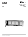
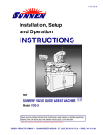
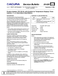
CHAPTER 12
CNC Program Codes
General
The next three chapters contain a description of the CNC program codes and parameters supported by
the M-Series Control. The M-Series Control has some G codes and parameters that are modal, and
some that are "one shots." The G codes and parameters that are modal will stay in effect until a new G
code or parameter is issued. One shots are effective for the current line only. For example, a movement
command of G1, which is modal, will remain in effect until a different movement command is issued,
such as G0, G2, G3, etc.
Miscellaneous CNC Program Symbols
D - Tool Diameter Offset Number
D is used to select the Tool Diameter Offset from the offset library. The D code values are stored in the
Offset Library. Tool Diameter Offsets can be specified anytime before Cutter Comp is turned on (G41
or G42). Once specified, the offset amount is stored and will only be changed when another D code is
entered. The Tool Diameter Offset (D) can be placed on a line by itself or on a line with other G-codes.
Example:
X0Y0F10
G41 D2
G1X0Y0
X1Y1.25
X2Y1.4
G40
G42
;
; Enables cutter comp left with diameter D2.
;
; Cutter compensated moves
;
; Cutter compensation off
; Enables cutter comp. right (still using D2)
E - Select Work Coordinate System
E1 through E6 select among the six work coordinate systems. They are equivalent to G54 through G59.
F - Feedrate
The F command is used to set the cutting feedrate. The feedrate is expressed in units/minute. The
programmed feedrate may be modified by the feedrate override knob (2% - 200%). The default feedrate
is 3.0 units/minute. Units may be inches or millimeters.
M-Series Operator’s Manual
6/7/12
12-1
Example:
G90 G1 X1.0 F50
; linear mill to X1 at 50 units/minute
H - Tool Length Offset Number
H is used to select the Tool Length Offset Number. The H code offset amounts are stored in the file
Offset Library. Tool Length Offsets can be specified anytime before a G43 or G44 is issued. Once
specified the offset amount is stored and will only be changed when another H code is entered. The
Tool Length Offset (H) can be placed on a line by itself or on a line with other G-codes. H00 is always
a 0.0 length offset.
Example:
G43 H1 Z3
G1X0Y1
H3
X1Y1.25
G0H5
; Selects offset corresponding to H1, moves to Z3
;
; Selects offset corresponding to H3.
;
; Selects offset corresponding to H5.
* NOTE: See Tool/Offset Library Edit (Chapter 4) for editing instruction for the offset library.
For information on length compensation functions see G43 and G44 in Chapter 13.
N - Block Number
Block numbers are used to identify CNC program lines. Block numbers are optional, but can be used
with the Search Function (See Main Screen Search option in Chapter 2). Block numbers also can make
reading the NC files easier.
Example:
N1 G90 G17 M25
N2 G0 X0 Y0 Z0
O - Program Number
The O program number allows you to identify your program with a certain number.
If the program number is 9100-9999, the G codes from the O number through the next M99 will be
extracted and placed in a separate subprogram/macro file. The lines will not be executed until the
resulting file is called with M98 or G65.
Example:
O1521
N1 G90 G17 M25
N2 G0 X0 Y0 Z0
P - Parameter
12-2
M-Series Operator’s Manual
6/7/12
P can correspond to Dwell Time, subprogram number, or a general parameter in canned cycles. This is
used as a variable for any of those values in the NC file.
Examples:
G4 P1.32
; Pause execution for 1.32 seconds
G10 P73 R.1 ; Set parameter #73 (G73 retract) to .1 inches
Q - Parameter
Q is used as a depth parameter in canned drilling cycles.
Example:
G73 X1.5 Y2.0 Z-.75 R.25 Q.25 F5 ; Q Sets the depth cut at .25
R - Radius, Return Point, Parameter
R can represent the radius, a return point, or a general parameter. This is used as a variable for any of
those values in the NC file. R is similar to the P parameter.
Examples:
G10 D5 R.5
G81 X0 Y0 Z-.5 R.1 F15
; set D5=0.5
; drill to Z-.5 with return height of .1
S - Spindle Speed Setting
Specifying a spindle speed causes the automatic spindle speed setting to be immediately updated.
Setting the spindle speed does not cause the spindle to start. The maximum spindle speed is used to
compute the output value to the spindle speed control circuit.
Example:
S1400 M3
; Starts the spindle CW at 1400 RPM
* NOTE: The Spindle Speed is used in conjunction with the maximum spindle speed to
determine the actual spindle speed output to the PLC. Also, this only works when a VFD
(Variable Frequency Drive) spindle drive is connected.
T - Select Tool
Prompts the operator to insert the proper tool or change tools, when M6 is encountered.
Example:
T1 M6
T2
; Prompt operator to load tool number 1
; no action
M-Series Operator’s Manual
6/7/12
12-3
G0X0Y0
M6
; move to X0 Y0
; prompt operator to load tool number 2
: - Visible Comment Identifier
The colon (:) is used to indicate the start of a comment line within a CNC program. The colon must be
the first character on the line.
Example:
: select absolute positioning
G90
: XY plane
G17
:Visible comments will be displayed on screen with the G-codes.
; - Internal Comment Identifier
The semicolon (;) is used to indicate the start of an internal comment within a CNC program line. All
characters after the semicolon are ignored when the program is run. Internal comments are used to
document NC programs or temporarily omit the remainder of a line.
Example:
G90
; select absolute positioning
G17
; XY plane
G1 X1 Y1 F10
G0 ; X0 Y0 ; G0 selected with no movement
12-4
M-Series Operator’s Manual
6/7/12
CHAPTER 13
CNC Program Codes: G-codes
G-code
G00
G01
G02
G03
G04
G09
G10
G17
G18
G19
G20
G21
G28
G29
G30
G40
G41
G42
G43
Group
* A
A
A
A
B
B
B
* C
C
C
* K
L
B
B
B
*
D
D
D
Description
Rapid Positioning
Linear Interpolation
Circular or Helical Interpolation CW
Circular or Helical Interpolation CCW
Dwell
Exact Stop
Parameter Setting
Circular Interpolation Plane Selection XY
Circular Interpolation Plane Selection ZX
Circular Interpolation Plane Selection YZ
Select Inch Units
Select Metric Units
Return to Reference Point
Return from Reference Point
Return to Secondary Reference Point
Cutter Compensation Cancel
Cutter Compensation Left
Cutter Compensation Right
Tool Length Compensation (+)
E
G44
E Tool Length Compensation (-)
G49
* E Tool Length Compensation Cancel
G50
M Scaling/Mirroring Off (Optional)
G51
M Scaling/Mirroring On (Optional)
G52
B Offset Local Coordinate System Origin (Optional)
G53
B Rapid Position in Machine Coordinates (Optional)
G54
L Select Work Coordinate System #1 (Optional)
G55
L Select Work Coordinate System #2 (Optional)
G56
L Select Work Coordinate System #3 (Optional)
G57
L Select Work Coordinate System #4 (Optional)
G58
L Select Work Coordinate System #5 (Optional)
G59
L Select Work Coordinate System #6 (Optional)
G61
F Exact Stop Mode
G64
*
F Cutting Mode
G65
J
Call Macro (Optional)
G73
G High Speed Peck Drilling
G74
G Counter Tapping (Optional)
G80
* G Canned Cycle Cancel
G81
G Drilling and Spot Drilling
G82
G Drill with Dwell
G83
G Deep Hole Drilling
M-Series Operator’s Manual
6/7/12
13-1
G84
G85
G89
G90
G91
G92
G98
G99
G117
G118
G119
*
*
*
G
G
G
H
H
B
I
I
C
C
C
Tapping (Optional)
Boring
Boring with Dwell
Absolute Positioning Mode
Incremental positioning Mode
Set Absolute position
Initial Point Return
R Point Return
Rotation of Plane Selection XY
Rotation of Plane Selection ZX
Rotation of Plane Selection YZ
NOTES:
*All the default G-codes have been marked with the symbol " * ".
*A given line of a program may contain more than one G-code.
*If several G-codes from one group are used in the same line, only the G-code specified last will remain
active.
*G-codes from group B are of "one shot" type (active only in the line in which they are specified). All
other G-codes are modal (active until another G-code of the same group is specified).
*If a G-code from group A is used in a canned cycle mode, the canned cycle will be canceled. Canned
cycle G-codes, however, have no effect on G-codes from group A.
G00 - Rapid Positioning
G0 moves to the specified position at the maximum motor rate. The coordinates may
be either absolute positions (G90) or incremental positions (G91). G0 is modal and
remains in effect until another positioning mode (G1, G2, G3 etc.) is commanded.
G0 is the default-positioning mode.
When the Z axis is commanded to move in the + direction, the Z axis will move up to its new position
first, then the other axes will move to their new position along a straight line.
When the Z axis is commanded to move in the - direction, all axes but the Z axis will move to their new
position along a straight line, then the Z axis will move down to its new position.
Example:
G0 X0.0 Y0.0 Z0.0
* NOTE: G0 moves are only affected by the feedrate override knob if rapid override (AUX1) is
ON.
13-2
M-Series Operator’s Manual
6/7/12
G01 - Linear Interpolation
G1 moves to the specified position at the programmed feedrate. The
coordinates may be either absolute positions (G90) or incremental
positions (G91). The movement will be along a straight line. G1 is modal
and remains in effect until another positioning mode (G0, G2, G3 etc.) is
commanded.
Example:
G01 X2 Y3 Z4 W5 F10
G91 X6 Y7
Z3 W4 F20
G02 & G03 - Circular Or Helical Interpolation
G2 moves in a clockwise circular motion, and G3 moves in a
counterclockwise circular motion. This clockwise and counterclockwise
motion is relative to your point of view, however. See the diagram below.
The X, Y or Z position specified in the G2 or G3 command is the end
position of the arc, and may be an absolute position (G90) or an
incremental position (G91). G2 and G3 are modal and remain in effect
until another positioning mode (G0, G1, etc.) is commanded.
* NOTE: When using G18, the G2 command moves in a counterclockwise direction in the XZ plane.
The axes included in the currently selected circular plane (G17, G18, or G19) will move in a circular
motion. Any other axes specified will move along a straight line (helical movement).
The programmed feedrate is used for the interpolated motion along the movement of all axes.
Helical and circular motion can be programmed in two different ways: specifying the final point and the
radius of the arc, or specifying the final point and the parameters I, J, K (center point of the arc as
incremental values from the start position).
* NOTE: For closed circles (arc of 360 degrees), use method 2: specify final point and
parameters I, J and K. Method 1 (specify final point and radius) will not work.
M-Series Operator’s Manual
6/7/12
13-3
METHOD 1: USING FINAL POINT AND RADIUS
The commands G2 and G3 will have the following structure:
G2 Xa Yb Zc Rd
G3 Xa Yb Zc Rd
where a, b, and c will be the X, Y, and Z coordinates of the final point of the arc, and d will be the
radius.
In most cases there will be two possible arcs of the same radius connecting two given points. This
occurs because the center of the arc is not specified. To choose the bigger arc, make the radius negative.
To choose the smaller arc, make the radius positive. See examples 1 and 2 for graphical explanations of
this concept.
Example 1 (small arc solution: positive radius):
G17 G90 F25
;select XY plane and absolute positioning
G00 X1.0 Y1.0 Z0 ;rapid to start position x1, y1, Z0
G02 X2 Y2 Z0 R1 ;arc to X2 Y2 Z0 with radius of 1
; (small arc solution)
Example 2 (big arc solution: negative radius):
G17 G90 F25
;select XY plane and absolute positioning
G00 X1.0 Y1.0 Z0
;rapid to start position x1, y1, Z0
G02 X2 Y2 Z0 R -1 ;arc to X2 Y2 Z0 with radius of 1
; (big arc solution)
13-4
M-Series Operator’s Manual
6/7/12
METHOD 2: USING FINAL POINT AND PARAMETERS I, J, K
Another way to specify a helical or circular operation is using the parameters I, J, K instead of
the
radius R. The parameters I, J, and K are the incremental distances from the start point to the center of
the arc.
I = X center - X start (valid for G17 & G18)
J = Y center - Y start (valid for G17 & G19)
K = Z center - Z start (valid for G18 & G19)
Examples:
Circular motion (See graph in method 1, example 2)
G17 G90 F25
G00 X1.0 Y1.0 Z0
G02 X2 Y2 Z0 J1
;select XY plane and absolute positioning
;rapid to start position x1, y1, Z0
;arc to X2 Y2 Z0 with radius of 1
Helical motion
G17 G90 F30
; select XY plane and absolute positioning
G00 X3.0 Y2.0 Z1.0
; rapid to start position X3, Y2, Z1
G02 X2.0 Y1.0 I-1.0 J0.0 Z0.0 ; CW XY arc from X3,Y2 to X2,Y1.
; Center at X2, Y2
; Helical Z move from 1 to 0
M-Series Operator’s Manual
6/7/12
13-5
G04 - Dwell
G4 causes motion to stop for the specified time. The P parameter is used
to specify the time in seconds to delay. G4 causes the block to decelerate
to a full stop.
The minimum delay is 0.01 seconds and the maximum is 327.67 seconds.
The dwell time is performed after all motion and M functions on the line.
If the P parameter is not specified, X will be used instead. If neither P nor
X is specified, the default dwell time of 0.01 seconds will be used.
Example:
G0 X1 Y1 ; rapid to X1 Y1
G4 P2.51 ; pause for 2.51 seconds
X2 Y2
G09 - Exact stop
G9 causes motion to decelerate to a stop. G9 is equivalent to G4 P0.01. G9 is not
modal; it is only effective for the block in which it appears. See G61 (exact stop
mode).
Example:
G9 G0 X1 Y1
X2 Y2
; rapid to X1 Y1 and stop
; continue to X2 Y2
G10 - Parameter Setting
G10 allows you to set parameters for different program operations.
Examples:
G10 P73 R.05
G10 P83 R.05
G10 P81 R15
G10 H5 R-1.3
G10 D3 R.25
; Sets the peck drilling retract amount to .05
; Sets the deep drill rapid down clearance to .05
; sets G81 to use M15 instead of Z movement
; Sets tool length offset #5 to -1.3 in the
; Offset Library
; Sets tool diameter offset #3 to .25 in the
; Offset Library
G17, G18, G19 - Circular Interpolation Plane Selection
G17, G18, and G19 select the plane for circular interpolation commands (G02 & G03). G17 is the
default plane. See figure under G2 and G3.
G17 is the XY plane
G18 is the ZX plane
13-6
M-Series Operator’s Manual
6/7/12
G19 is the YZ plane
G20 - Select Inch Units
G20 selects inch units, affecting the interpretation of all subsequent dimensions and feedrates in the job
file. G20 does not change the native machine units as set on the control setup menu.
G21 - Select Metric Units
G21 selects metric units, affecting the interpretation of all subsequent dimensions and feedrates in the
job file. G21 does not change the native machine units, as set on the control setup menu.
G28 - Return to Reference Point
G28 moves to the first reference point, by way of an intermediate point. The location of the reference
point, in machine coordinates, may be set in Work Coordinate System Configuration. The intermediate
point is specified in the local coordinate system, and may be at the current location (resulting in a move
directly to the reference point). If an intermediate point is specified, only those axes for which positions
are specified will be moved. If no axes are specified, all axes will be moved. The location of the
intermediate point is stored for later use with G29.
Examples:
G28 G91 Z0
; move Z axis directly to reference point
; (X and Y don't move)
G28 G91 X-.5 Y0 Z0
; move X -.5, then move all three axes to
; reference point
G28 G90 X2 Y4 Z.1
; move all axes to (2,4,0.1), then to
; reference point
G28
; move all axes to the reference point
; (no intermediate point)
* NOTE: As with G0 positioning moves, the Z-axis will move separately. If Z is moving up (the
usual case) Z will move first, then the other axes. If Z is moving down, the other axes will move
first, then Z. Because of this, it is rarely necessary to specify an intermediate point different from
the current position.
G29 - Return from Reference Point
M-Series Operator’s Manual
6/7/12
13-7
G29 moves all axes to the intermediate point stored in a preceding G28 or G30 command. It may be
used to return to the workpiece. If a position is specified, the machine will move to that position (in
local coordinates) after reaching the intermediate point. G29 may only be specified after G28 or G30,
though there may be intervening moves.
Examples:
G29
; move all axes back from reference point to
; intermediate point
G29 X1 Y2
; move all axes to intermediate point, then move to X1 Y2
* NOTE: As with G0 positioning moves, the Z-axis will move separately. If Z is moving up, Z
will move first, then the other axes. If Z is moving down (the usual case for G29), the other axes
will move first, then Z.
G30 - Return to Secondary Reference Point
G30 functions exactly like G28, except that by default it uses the second reference point from the Work
Coordinate System Configuration table, and the P parameter may be used to request either reference
point.
Examples:
G30 G91 Z0 ; move Z axis directly to second reference point
G30 P1
; move all axes to first reference point
* NOTE: G30 P1 is equivalent to G28.
G40, G41, G42 -Cutter Compensation
G41 and G42 in conjunction with the selected tool diameter (D code) apply cutter compensation to the
programmed toolpath.
G41 offsets the cutter tool one half of the tool diameter selected with a D code, to the
left of the workpiece, relative to the direction of travel.
G42 offsets the cutter tool one half of the tool diameter selected with a D code, to the
right of the workpiece, relative to the direction of travel.
G40 cancels G41 and G42.
Example:
G41 D03
; Tells the machine to compensate left half of the
13-8
M-Series Operator’s Manual
6/7/12
; Diameter of the amount that corresponds to D03 in the
; Tool Library
Whenever cutter compensation is applied, the following factors must be taken into account in order to
obtain proper results.
1. The cutter diameter compensation function (G41, G42) must be implemented before the cutter tool
reaches the starting cutting point.
Example 1:
G0X0Y0
G42 D3
G0X.5Y2
G1x4.1Y2
G40
G0X5Y0
;Rapid tool to X0, Y0
;Turn cutter compensation on, with a diameter of D3
;Rapid to X0.5, Y2
;Linear cut to X4.1, Y2.
;Cut to X4.1 to clear material.
;Turn cutter compensation off.
;Rapid to X5, Y0.
You may want to add .1 or .05 inches on the final position for the last cut to clear the material.
M-Series Operator’s Manual
6/7/12
13-9
* NOTE: The diameter compensation statement G42 is placed before G0 X.5 Y2. As a result, the
compensation is applied before the cutter reaches the starting cutting point X.5 Y2.
2. If the cutter is down, then the cutter compensation lead-in must always come from an appropriate
direction. Otherwise, the workpiece will be incorrectly cut, and the cutter tool could be damaged. One
way to avoid this problem is by always keeping the cutter above the workpiece whenever a transition is
being made to a new starting cutting point. If for some reason this was not possible, then the G-code
program should be written so that the cutter compensation lead-in paths do not interfere with the space
occupied by the workpiece. Example 2 illustrates a possible harmful outcome of programming an
inappropriate lead-in direction.
Example 2:
WRONG WAY
G0 X0Y0
G42 D5
G1 X.75Y-1 F5
X3.6
G40
G0 X4Y-2
* NOTE: This problem could have been avoided by selecting a transitional point between X0 Y0
and X.75 Y-1. A transitional point such as X-1 Y-1 would properly modify the lead-in path,
keeping the cutter from damaging the corner of the workpiece. Example 3 shows the correct way
of performing this operation.
Example 3:
13-10
M-Series Operator’s Manual
6/7/12
CORRECT
G0X0Y0
G42D5
G0X0Y-1
G1X.75Y-1
X3.6
G40
3. Lookahead. When the control machines any rapid traverse (G0), line (G1), or arc (G2, G3) with tool
diameter compensation enabled, the program will look up to 10 consecutive events ahead of the current
event in order to anticipate toolpath clearance problems. Lookahead ensures that compensated tool
paths don't overlap in programmed part sections where there is not enough clearance for the tool. The
figure below shows a compensated tool path, and the actual toolpath after Lookahead corrects the
clearance problem:
The number of Lookahead events the control scans is preset to 10. You can change the number of
consecutive events from 1 to 10 by changing parameter 99 (refer to Chapter 16 for more information).
G43, G44, G49 - Tool Length Compensation
G43 and G44 apply tool length compensation to a selected tool to allow the control to utilize multiple
tools in a single CNC program.
M-Series Operator’s Manual
6/7/12
13-11
G43 applies positive compensation (from Z zero up). Work from part surface up.
G44 applies negative compensation (from Z zero down), used only when there is an
absolute machine home. The spindle face is considered a zero length tool and all
offsets are from there down.
G49 cancels tool length compensation (also canceled by issuing G43 H00).
Example:
G43 H01
; tells the machine to offset the amount that
; corresponds to H01 in the Offset Library
G50, G51 - Scaling / Mirroring (Optional)
G50 and G51 scales program G-codes relative to a scaling center point defined as position (X, Y, Z).
A G51 applies scaling/mirror to all positions, lines, and arcs following this G-code until a G50 is
entered. Specify scaling factors with a value I, J, K. The X, Y, and Z parameters are the coordinates of
the scaling center. If the scaling center is not specified, the default scaling center is the current cutter
position as shown on the DRO. To mirror, enter a negative value for the scaling factor.
Example, Scaling:
G51 X0.0
G00 X0.0
G01 X1.0
G01 X1.0
G01 X0.0
G01 X0.0
G01 X0.0
G50
Y0.0
Y0.0
Y0.0
Y1.0
Y1.0
Y0.0
Y0.0
Z0.0 I3.0 J2 K1 ;turn scaling on
Z1.0
;rapid to x0, y0, Z1
Z1.0
;line to X1, Y0, Z1
Z1.0
;line to X1, Y1, Z1
Z1.0
;line to X0, Y1, Z1
Z1.0
;line to X0, Y0, Z1
Z0.0
;line to X0, Y0, Z0
;cancel scale
For this G51, the following program lines were scaled 3:1 in the X direction, 2:1 in the Y direction, and
1:1 in the Z direction. If no scale factor is specified, the default is 1:1 for all axes.
Example, Mirroring:
G51 X-0.5 Y0.0 Z.0 I-1 J1 K1 ;turn mirror on.
G00 X0.0 Y0.0 Z1.0
;rapid traverse to X0, Y0, Z1
G01 X1.0 Y0.5 Z1.0
;line to X1, Y.5, Z1
G01 X0.0 Y1.0 Z1.0
;line to X0, Y1, Z1
G01 X0.0 Y0.0 Z1.0
;line to X0, Y0, Z1
G50
;cancel scale
13-12
M-Series Operator’s Manual
6/7/12
If scaling factors are the same for all the axes, parameter P can be used.
Example:
G51 X1.0 Y2.0 Z0.0
P2.5
;scale all axes a factor of 2.5.
If an arc is scaled with uneven scaling factors, the result will depend on how the arc center and radius
were specified:
1.If the arc radius was specified with R, the radius will be scaled by the larger of the two circular
plane scale factors. The result will be a circular arc between the scaled arc start and the scaled arc
end.
2.If the arc center was specified with I, J, and/or K, the centers will be scaled by the appropriate axis
scale factors. The result will be a circular arc from the scaled arc start, around the scaled center,
and usually with a line from the end of the circular arc to the scaled arc end.
3.In no case can an ellipse be generated using scaling.
G52 - Offset Local Coordinate System (Optional)
G52 shifts the local coordinate system origin by a specified distance. Multiple G52 codes are not
cumulative; subsequent shifts replace earlier ones. The G52 shift may therefore be canceled by
specifying a shift of zero. If you are using multiple coordinate systems, the G52 shift amount will affect
all coordinate systems.
Example:
G0 X0 Y0
M98 P9100
G52 Y4
G0 X0 Y0
M98 P9100
G52 Y0
; move to origin
; call subprogram
; shift coordinate system 4 inches in Y
; move to new origin
; call subprogram again with new coordinates
; restore unshifted coordinate system
G53 - Rapid Positioning in Machine Coordinates (Optional)
G53 is a one shot code that performs a rapid traverse using machine coordinates. It does not affect the
current movement mode (G0-G3) or coordinate system (G54-G59). G53 may only be used with
absolute positioning (G90).
M-Series Operator’s Manual
6/7/12
13-13
Example:
G53 X15 Y4 Z0
; move to 15,4,0 in machine coordinates
G54 - G59 - Select Work Coordinate System (Optional)
G54 through G59 select among the six work coordinate systems. Subsequent absolute positions will be
interpreted in the new coordinate system.
Example:
G54 G0 X0 Y0 Z0
G2 X1 I.5 Z-.5
G0 Z.1
G55 X1 Y1
; select first WCS, move to origin
; mill something...
; select second WCS, move to 1,1
Extended Work Coordinate Systems: Defined bit 1 of parameter 5 (add 2 to value) to enable extended
work coordinate system features on part setup a WCFG screens. When enabled, there are 18 workpiece
origins instead of six) and four return points (instead of two.) The extra workpiece origins are not
accessible on the WCFG menu; they can only beset using Set Part 0/Position. In G-codes, the 12
additional workpiece origins may be selected with either “G54 P1” through “G54 P12” or “E7” through
“E18.” In G-codes, the additional return points may be selected with “G30 P3” and “G30 P4.”
G61 - Exact stop mode
G61 invokes the exact stop mode. This forces deceleration to an exact stop at the
end of each block (equivalent to G9 in each block). G61 is modal and remains in
effect until canceled with G64 (cutting mode).
Example:
G0 X0 Y0
G61 X2 ; exact stop mode on: decel to stop at X2
X4
; move to X4 and stop
X5
; move to X5 and stop
G64 - Cutting mode (continuous, without exact stop)
G64 invokes cutting mode and cancels exact stop mode. No exact stops are
performed at the end of each block. However, acceleration and deceleration is still
performed. G64 is modal and remains in effect until exact stop mode (G61) is
selected. Cutting mode is the default at the start of each program.
Example:
G0 X0 Y0
G64 X2 ; exact stop mode off: no stop at X2
13-14
M-Series Operator’s Manual
6/7/12
X4
X5
; continue to X4 without stop
; continue to X5 without stop
G65 - Call Macro (Optional)
G65 calls a macro with user-specified values. A macro is a subprogram that executes a certain operation
(e.g. drill pattern, contours, etc.) with values assigned to variable parameters within the operation.
Calling methods:
G65 Pxxxx Lrrrr Arguments
or
G65 "program.CNC" Lrrrr Arguments
Where xxxx is the macro number (in file Oxxxx.CNC, 0000-9999 allowed, leading zeros required in
filename), rrrr is the repeat value, "program.CNC" is the name of the macro file, and Arguments is a list
of variable identifiers and values.
Arguments to macro calls are specified by using letters A-Z, excluding G, L, N, O, and P.
Macros are written just like normal programs. However, macro programs may access their arguments by
using #A, #B, etc., or by using numbers: #1 for A, #2 for B, etc. (exceptions: #4-6 for I-K, #7-11 for DH). Arguments I, J, and K can be used more than once in a macro call, with the first set of values stored
as #4-6, the second as #7-9, etc., to a maximum of 10 sets.
* See example at the end of this G65 section.
A macro can use the negative of an argument by placing a minus sign before the '#'. No other arithmetic
operations are supported.
Macros can call other macros (up to 4 levels of depth), Macro M-functions, and subprograms. Macro Mfunctions and subprograms can similarly call macros.
Macros 9100 - 9999 may be embedded into a main program, using 091xx to designate the beginning of
the macro and M99 to end it. CNC7 will read the macro and generate a file 091xx.CNC, but will not
execute the macro. It will be executed when G65 is issued.
Example 1:
Main program:
G65 "TEST.CNC" A5 B3 X4
Macro TEST.CNC:
G1 X#X Y#A Z-#B
This call will produce
G1 X4 Y5 Z-3
Example 2:
M-Series Operator’s Manual
6/7/12
13-15
Main program:
G65 "TEST2.CNC" I5 J3 K40 I-1 J2 I0 J0
Macro TEST2.CNC:
G1 X#4 Y#5 F#6
G1 X#7 Y#8 F#9
G1 X#10 Y#11 F#12
This call will produce
G1 X5 Y3 F40
G1 X-1 Y2
G1 X0 Y0
Example 3:
Suppose a piece is to have notches of different lengths and depths along the x-axis:
The macro variables would handle the length in the Y direction and depth in the Z direction:
O0002
G90 G1 Z0 F30
Z#Z F5
G91Y#Y F10
G90 G0 Z0.1
;Cut to variable depth
;Cut variable length
;Retract
The main program would call this macro five times, each time specifying the depth and length required.
13-16
M-Series Operator’s Manual
6/7/12
:Main Program
G90 G0 X1 Y1 Z0.1
G65 P0002 L1 Y1 Z.25
G90 G0 X2.5 Y1
G65 P0002 L1 Y1.5 Z.5
G90 G0 X4 Y1
G65 P0002 L1 Y2 Z.25
G90 G0 X5.5 Y1
G65 P0002 L1 Y1.5 Z.5
G90 G0 X7 Y1
G65 P0002 L1 Y1 Z.25
:End program
M-Series Operator’s Manual
;Move to first notch
;Call macro and assign Y=1" and Z=.5"
;Call macro and assign Y=1.5" and Z=.5"
;Call macro again
;Call macro again
;Call macro again
6/7/12
13-17
G73, G80, G81, G82, G83, G85, G89 - Canned Drilling
Cycles
G74, G84 (Optional) - Canned Tapping Cycles
G code
G73
G74
G80
G81
G82
G83
G84
G85
G89
-Z direction Operation at
(machine hole) bottom of hole
+Z direction
Intermittent
Rapid traverse
Feed
---------(Set with the Q
parameter)
Feed
Spindle CW,
Feed
then
Dwell (Set with
the
P parameter)
parameter)
----------
----------
Feed
---------Rapid traverse
---------Feed
Dwell (Set with Rapid traverse
the P
parameter)
Intermittent
Rapid traverse
Feed
---------(Set with the Q
parameter)
Feed
Spindle CCW, Feed
then
Dwell (Set with
the P
parameter)
Feed
Feed
---------Feed
Dwell (Set with Feed
the P
parameter)
Use
High speed
peck drilling
cycle
Counter
tapping
(Left-hand
thread)
Cancels canned
cycles
Regular and
spot drilling
cycles and
air drill cycle
Regular and
counter boring
cycles,
spotfacing
Peck and deep
hole drilling
cycles
Tapping
(Right-hand
thread)
Boring cycle
Boring cycle
Table 1. Canned drilling and tapping cycles
13-18
M-Series Operator’s Manual
6/7/12
Canned Cycle Operation
Operation 1
Operation 2
Operation 3
Operation 4
Operation 5
Operation 6
Position the X, Y-axis.
Rapid traverse to the position labeled R.
Machine hole.
Bottom hole operation.
Return to point R.
Rapid traverse to initial point.
Canned cycle G-code syntax
(Cycle codes do not have to be on the same line)
G ____
Canned cycle G-code from table 1.
X ____
X position of the hole to be drilled.
Y ____
Y position of the hole to be drilled.
Z ____
Specifies point Z in figure 1.
In incremental mode Z is measured from point R.
In absolute mode Z is the position of the hole bottom.
M-Series Operator’s Manual
6/7/12
13-19
R ____
Specifies the distance to point R (figure 1) with an absolute or
incremental value.
Q ____
Determines the cut-in depth for the G73 and G83 cycles.
P ____
Sets the dwell time at the bottom of the holes for G74, G82, G84, and
G89 cycles. The dwell time is measured in seconds (same as G04).
F ____
Sets the feed rate. Remains the feedrate even after G80 cancel canned
cycles.
K ____
Sets the number of repeats for drilling cycles. Operations 1 through 6 of
figure 1 will be repeated K number of times. If K is not specified K = 1.
K is only useful when using incremental positioning mode (G91) and is
not retained from cycle to cycle. In absolute mode, K causes the
drilling of the same hole in the same position K times.
* NOTE: Canned cycles are modal and should be canceled with G80. However G00, G01, G02
and G03 will also cause the cancellation of canned cycles. All parameters are stored until canned
cycles are canceled except for the hole position and K, which must be set each time the cycle is
used. When G80 is issued the movement mode will be the last one issued (G0, G1, G2, G3).
Canned cycles will not be performed unless X and/or Y is specified.
When performing canned cycle operations, the distances can be either incremental or absolute,
depending on the current active mode (G90 = absolute, G91= incremental). Figure 2 illustrates canned
cycle Z-axis distances in both modes.
Figure 2: Canned Cycle Absolute and Incremental modes
* NOTE: In incremental mode the Z depth of the hole is measured from R, and R is measured
from the initial tool position.
13-20
M-Series Operator’s Manual
6/7/12
Example:
(Part surface height is Z = 0, initial tool position is X.50 Y1.0 Z.625. Drill 0.50 deep
hole at X1.0 Y1.0; clearance height (R) is 0.10 above surface.)
; Absolute
G90
G81 X1 Y1 R.1 Z-.5
G80
; Incremental
G91
G81 X.5 Y0 R-.525 Z-.6
G80
G73 - High Speed Peck Drilling
G73 is the peck drilling cycle. The hole is drilled in a series of moves: down at feedrate a distance Q, up
at the rapid rate the retract distance, and then down again at feedrate. The retract amount is set with G10
as shown in the example below.
Example:
G90
; Absolute positioning
G01 X3.00 Y1.50 Z.5
; G01 mode before canned cycle
G98
; Set for initial point return
G10 P73 R.1
; Sets the retract amount to .1
G73 X3.250 Y1.75 Z-.650 R.1 Q0.325 F3
; Peck drill at X3.25 Y1.75
X4.5 Y3.5
; Peck drill at X4.5 Y3.5
G80
; Cancel canned cycle, return
; to G01
G74 - Counter Tapping (Optional)
M-Series Operator’s Manual
6/7/12
13-21
G74 performs left-hand tapping using a floating tap head. The spindle speed and feedrate should be set
and the spindle started in the CCW direction before issuing G74. By default, G74 uses M3 to select
spindle CW (at the bottom of the hole) and M4 to re-select spindle CCW (after backing out of the hole).
Alternate M functions may be specified by setting parameters G74 (for CCW) and G84 (for CW).
The tap will continue to cut a short distance beyond the programmed Z height as the spindle comes to a
stop before reversing. When tapping blind holes, be sure to specify a Z height slightly above the bottom
of the hole to prevent the tool from reaching bottom before the spindle stops. The exact distance you
must allow will depend on your machine and the diameter and pitch of the tapping tool.
* WARNING: Do not press FEED HOLD or CYCLE CANCEL while the tap is in the hole.
Example:
M4 S500 F27.78
; start spindle CCW, set up for 18 pitch tap
G74 X1 Y1 R.1 Z-.5 ; counter-tap a 0.5 deep hole at X1 Y1
Y1.5
; ... and another one at X1 Y1.5
G80
; cancel canned cycles
13-22
M-Series Operator’s Manual
6/7/12
G81 - Drilling and Spot Drilling
G81 is a general purpose drilling cycle. The hole is drilled in a single feedrate move, and then the tool is
retracted at the rapid rate.
Example:
G90
; Absolute positioning
G01 X3.00 Y1.50 Z.5
; G01 mode before canned cycle
G99
; Set for R point return
G81 X3.250 Y1.75 Z-.650 R.1 F3 ; Drill at X3.25 Y1.75
X4.5 Y3.5
; Drill at X4.5 Y3.5
G80
; Cancel canned cycle, return to G1
G81 - Drill Cycle Transformation to G81 Air Drill Cycle
G81 may be modified to execute an M function instead of moving the Z-axis by setting parameter #81 to
the desired M function. Example use is for air-actuated drills.
Example: Execute M39 each time a new G81 position is given:
G10 P81 R39
G81 X5
Y3
; Set parameter 81 to 39 (G81 air drill with M39)
; Move to X5 and execute M39
; Move to Y3 and execute M39
To revert to Z-axis drilling, specify M function #-1.
Example:
G10 P81 R-1
; Set parameter 81 to -1 (G81 drilling cycle)
M-Series Operator’s Manual
6/7/12
13-23
M function #39 is designed for general air drill use. See the description of M39 in the M functions
section.
A different M function may be used instead, but any M function used must be a macro file that uses the
M103 and M104 commands to time the cycle (see the example in the M function section under M103).
If the macro file does not use M103, the control will automatically cancel the job 1/2 second after
starting G81. For information on creating customized M functions, review Macro M functions in the
next chapter.
The M39 default air drill cycle has a time out of 2.0 seconds. As a result, if the cycle does not complete
within 2 seconds then the cycle aborts and the output relay is turned off under PLC program control.
* NOTE: The PLC program must be involved in the execution of the cycle. The PLC program is
responsible for turning on relays based on M function requests and the status of program
execution. The PLC program must also stop all programmed machine functions when the
program is canceled. See the M39 description (Chapter 13) for a sample of an air drill cycle M
function.
G82 - Drill with dwell
G82 is a general purpose drilling cycle similar to G81. However, G82 includes an optional dwell at the
bottom of the hole before retracting the tool. This can make the depth of blind holes more accurate.
Example:
G82 X1 Y1 R.1 Z-.5 P.5
; drill to Z-.5, dwell .5 seconds
G83 - Deep hole drilling
13-24
M-Series Operator’s Manual
6/7/12
G83 is a deep hole drilling cycle. It periodically retracts the tool to the surface to clear accumulated chips,
then returns to resume drilling where it left off. The retract and return are performed at the rapid rate.
Because there may be chips in the bottom of the hole, the tool does not return all the way to the bottom at the
rapid rate. Instead it slows to feedrate a short distance above the bottom. This clearance distance is selected
by setting parameter 83 with G10 (see example below).
Example:
G10 P83 R.05
G83 X0 Y0 R.1 Z-2 Q.5
G80
; set clearance to .05"
; drill 2" deep hole in 0.5" steps
; cancel canned cycle
G84 - Tapping (Optional)
M-Series Operator’s Manual
6/7/12
13-25
G84 performs right-hand tapping using a floating tap head. The spindle speed and feedrate should be set
and the spindle started in the CW direction before issuing G84. By default G84 uses M4 to select
spindle CCW (at the bottom of the hole) and M3 to re-select spindle CW (after backing out of the hole).
Alternate M functions may be specified by setting parameters 74 (for CCW) and 84 (for CW). See G10
for examples.
The tap will continue to cut a short distance beyond the programmed Z height as the spindle comes to a
stop before reversing. When tapping blind holes, be sure to specify a Z height slightly above the bottom
of the hole to prevent the tool from reaching bottom before the spindle stops. The exact distance you
must allow will depend on your machine and the diameter and pitch of the tapping tool.
Note: If rigid tapping is enabled, the dwell P is ignored.
* WARNING: Do not press FEED HOLD or CYCLE CANCEL while the tap is in the hole.
Example:
M3 S500 F27.78
; start spindle CW, set up for 18 pitch tap
G84 X1 Y1 R.1 Z-.5 ; tap a 0.5 deep hole at X1 Y1
Y1.5
; ... and another one at X1 Y1.5
G80
; cancel canned cycle
13-26
M-Series Operator’s Manual
6/7/12
G85 - Boring
G85 is similar to G81, except that the tool is retracted with a feedrate move instead of a rapid move.
G85 may be used for tapping with reversing tap heads such as the Tapmatic NCR series.
Example 1:
G85 X1 Y1 R.1 Z-.5 ; bore a 0.5" hole at X1 Y1
G80
; cancel canned cycle
Example 2:
M3 S500 F27.78
; start spindle CW, set for 18 pitch tap
M109/1/2
; disable feedrate and spindle overrides
G85 X1 Y1 R.1 Z-.4 ; tap hole at X1 Y1 to a depth of 0.4"
M108/1/2
; reenable feedrate and spindle overrides
G80
; cancel canned cycle
M-Series Operator’s Manual
6/7/12
13-27
G89 - Boring cycle with dwell
G89 is similar to G85, except that it includes an optional dwell at the bottom of the hole before
retracting the tool.
Example:
G89 X1 Y1 R.1 Z-.5 P.1
G80
; bore 0.5" hole at X1 Y1, dwell .1 seconds
; cancel canned cycle
G90 & G91 - Absolute/Incremental Positioning Mode
G90 selects absolute positioning, and G91 selects incremental positioning. In absolute positioning, all
coordinates are relative to the origin (0,0,0,0). In incremental positioning, all coordinates are distances
relative to the last point.
G90
G91
Absolute positioning
Incremental coordinates
G90 X2 Y3
; moves the X and Y axes from the current position to
; the new position referenced from the absolute machine
Example:
zero.
G91 X1 Y0
13-28
; moves the X axis 1 inch referenced from the last X
; position, the Y axis does not move.
M-Series Operator’s Manual
6/7/12
;
G92 - Set Absolute Position
G92 sets the current absolute position to the coordinates specified. If you are using multiple work
coordinate systems, positioning in all coordinate systems will be changed by the same amount (-4 in X,
-3 in Y, +2 in Z, and -4 in W in the example below).
Example:
G0 X5 Y3 Z-2 W5 ; Moves to the specified location
G92 X1 Y0 Z0 W1 ; Sets the current position to the absolute
; position specified.
G98 - Initial Point Return
G98 sets the +Z return level to point I as pictured in Figure 1 in the Canned Cycle Section.
(G98 is the default setting)
G99 - R Point Return
G99 sets the +Z return level to point R as pictured in Figure 1 in the Canned Cycle Section.
G117, G118, G119 - Rotation of Pre-set Arc Planes
G117, G118 and G119 have the same functionality as G17, G18 and G19, respectively, except that they
include 2 optional parameters P and Q to specify the arc plane rotation away from the pre-set arc plane:
P specifies the arc plane angle of rotation (in degrees) around the first axis and Q specifies the arc plane
angle of rotation around the second axis.
For the G117 plane, the "first axis" is X and the "second axis" is Y.
For the G118 plane, the "first axis" is Z and the "second axis" is X.
For the G119 plane, the "first axis" is Y and the "second axis" is Z. If P and/or Q is not specified, the
angles are assumed to be 0 degrees. If both P and Q parameters are 0, then the plane is assumed to be an
orthogonal (pre-set) arc plane. The center of the arc can be specified by the user in a 3D form both in
M-Series Operator’s Manual
6/7/12
13-29
G17-G19 and in G117-G119 (all I, J, K values are allowed at the same time with G2 and G3). Any arc
center component outside the circular plane is ignored.
Example:
G00 X0 Y0 Z1
; rapid move
G03 G18 X1 Y0 Z0 K-1 F20
; arc mill
G00 X0 Y0 Z1.1
; retract move
G01 Z1
; move to start of contour
G03 G118 P1.000000 X0.9998 Y0.0175 Z0 K-1
; arc mill rotated about Z
* NOTE: G117-G119 will not be permitted while cutter compensation is turned on. Also,
scaling is not allowed while G117-G119 is specified and G117-G119 is not allowed while scaling
is active.
13-30
M-Series Operator’s Manual
6/7/12
CHAPTER 14
CNC Program Codes: M functions
M functions are used to perform specialized actions in CNC programs. Most of the M-series Control M
functions have default actions, but can be customized with the use of macro files.
Macro M functions
Most M-Series CNC M functions from 0 through 90 can be fully customized. Exceptions are M2, M6,
and M25 that can be customized, but will always move the 3rd (Z) axis to the home position before
executing the macro M function commands. No M functions above 90 may be customized with macros.
The default action listed will be performed unless that M function has been customized.
To create a macro for an M function, a file must be created in the C:\CNC7 directory. The file's name
must be CNC7.Mxx where xx is the M function number used to call the macro. M functions 0-9 must
use single digits in the filename (e.g. Use M3, not M03). The contents of the file may be any valid M
and G codes.
Each time the M function is encountered in a program, the macro file will be processed line by line.
* NOTE: Nesting of macro M functions is allowed. Recursive calls are not: if a macro M
function calls itself, the default action of the function will be executed.
Example: Turn on spindle with variable frequency drive and wait for "at speed" response.
Create file C:\CNC7\CNC7.M3 with contents as follows:
M94/1
M101/5
; request spindle start
; wait for up to speed signal
M2, M6, and M25 always move the Z-axis to the home position before any other motion. All other M
functions are performed after the motion of the current line is complete.
The M and G codes in a macro M function are not usually displayed on the screen as they are executed,
and are all treated as one operation in block mode. If you wish to see or step through macro M functions
(e.g. for testing purposes), set parameter #10 as follows:
0
1
2
Don't display or step through macro M functions
Display macro M functions, but don't step through them
Display and step through macro M functions
* NOTE: You cannot use block mode to step through a macro M function called using the G81
transformation (see Chapter 13); the action timer will expire before you can press CYCLE
START.
* NOTE: Only one M function per line is permitted.
M-Series Operator’s Manual
6/7/12
14-1
M00 - Stop For Operator
Motion stops, and the operator is prompted to press the CYCLE START button to continue.
Default action:
M100/75
M01 - Optional Stop for Operator
M1 has no effect unless optional stops are turned on. When optional stops are on, M1 is identical to M0.
Default action:
M100/75
; if optional stops are turned on.
M02 - Restart Program
M2 moves the Z-axis to the home position, performs any movement requested, and restarts the program
from the first line. The operator is prompted to press the CYCLE START button to continue.
M03 - Spindle On Clockwise
M3 requests the PLC to start the spindle in the clockwise direction.
Default action:
M95/2
M94/1
M04 - Spindle On Counterclockwise
M4 requests the PLC to start the spindle in the counterclockwise direction.
Default action:
M95/1
M94/2
M05 - Spindle Stop
M5 requests the PLC to stop the spindle.
Default action:
M95/1/2
M06 - Tool Change
M6 moves the Z-axis to the home position and stops the spindle and coolant. If an automatic tool
changer is installed, it then commands the tool changer to switch to the requested tool. Otherwise, it
prompts the operator to insert the tool and then press the CYCLE START button on the Operator Panel.
14-2
M-Series Operator’s Manual
6/7/12
Default action (no tool changer):
M25
;always does M25 first
M95/1/2/3/5
; turn off spindle & coolant
M100/75
; wait for CYCLE START button
Default action (tool changer installed):
M25
; always does M25 first
M95/1/2/3/5 ; turn off spindle & coolant
M95/16
; turn off tool changer strobe
M107
; send tool number to tool changer
M94/16
; turn on tool changer strobe
M101/32
; wait for acknowledge from changer
M95/16
; turn off tool changer strobe
M100/32
; wait for acknowledge from changer
Manual tool changes are selected by setting Parameter 6 to 0 in the Machine Parameters table. The
automatic tool changer is selected by setting Parameter 6 to 1 (see Chapter 6).
The PLC program must be involved in commanding an automatic tool changer and its associated strobe,
BCD and ACKnowledge lines. See Chapter 5 of the service manual for details of how such a PLC
program could be constructed.
M07 - Mist Coolant On
M7 causes the PLC to start the mist coolant system.
Default action:
M95/3
M94/5
M08 - Flood Coolant On
M8 causes the PLC to start the flood coolant system.
Default action:
M95/5
M94/3
M09 - Coolant Off
M9 causes the PLC to stop the coolant system.
Default action:
M95/3/5
M10 - Clamp On
M10 causes the PLC to activate the clamp.
M-Series Operator’s Manual
6/7/12
14-3
Default action:
M94/4
M11 - Clamp Off
M11 causes the PLC to release the clamp.
Default action:
M95/4
M25 - Move To Z Home
M25 moves the Z-axis to the home position at the Z-axis maximum rate. The Z home position defaults
to zero in machine coordinates, but may be changed by changing the Z coordinate of the first Reference
Point (on the Work Coordinate System Configuration screen).
Default action:
G0 <Z home >
M26 - Set Axis Home
M26 sets the machine home position for the specified axis to the current position (after the line's
movement). If no axis is specified, M26 sets the Z-axis home position.
Example:
M91/X
M26/X
M92/Z
M26
; home X axis to minus home switch
; set machine home for X-axis there
; home Z-axis to plus home switch
; set machine home for Z-axis there
M39 - Air Drill
M39 is a default air drill activation sequence with a timeout. The sequence of operations is as follows:
M94/15
M103/2
M100/15
M95/15
M104
; activate M function request 15
; start 2 second timer
; wait for input 15 to open
; deactivate M function request 15
; cancel timer
* NOTE: This program will be canceled by timer expiration if input 15 does not open within 2
seconds after M function request 15 is activated. The PLC program must be involved in taking
away the drill output when the CNC program stops:
Example:
; PLC program
CNC_program_running is INP65
M15 is INP47
14-4
M-Series Operator’s Manual
;program running indicator
;M function 15 indicator
6/7/12
drill_out is OUT5
;air drill output relay
drill_out = M15 & CNC_program running;Drill On if M94/15 and the
;CNC program is running. Drill
;Off if M95/15 or the CNC
;program is terminated.
M91 - Move to Minus Home
M91 moves to the minus home switch of the axis specified at the slow jog rate for that axis. After the
minus home switch is reached, the tool is moved back until the home switch untrips, and then the next
encoder index pulse is reached.
Example:
M91/X
G92 X-10
; move the X axis to the minus home switch.
; sets X minus home switch at -10
M92 - Move to Plus Home
M92 moves to the plus home switch of the axis specified at the slow jog rate for that axis. After the plus
home switch is reached, the tool is moved back until the home switch untrips, and then the next encoder
index pulse is reached.
Example:
M92/X
G92 X+10
; moves the X-axis to the plus home switch.
; Sets X plus home switch at +10
M93 - Release Motor Power
M93 releases the motor power for the axis specified. If no axis is specified, then all axes are released.
Example:
M93/X
M93
; releases the X axis.
; releases the motors on all axes.
* NOTE: Any axis freed within a CNC program should not be used in that program afterwards.
Incorrect positioning may result.
M94/M95 - Output On/Off
There are sixteen user definable M function requests. M94 and M95 are used to request those inputs to
turn on or off respectively. M function requests 1-16 are mapped to the PLC as inputs 33 - 48, as shown
in the following table:
On
M94/1
M94/2
M94/3
M94/4
M94/5
Off
M95/1
M95/2
M95/3
M95/4
M95/5
PLC Input
33
34
35
36
37
M-Series Operator’s Manual
On
M94/9
M94/10
M94/11
M94/12
M94/13
6/7/12
Off
M95/9
M95/10
M95/11
M95/12
M95/13
PLC Input
41
42
43
44
45
14-5
M94/6
M94/7
M94/8
M95/6
M95/7
M95/8
38
39
40
M94/14
M94/15
M94/16
M95/14
M95/15
M95/16
46
47
48
M Function request to PLC Input map
To use M94 and M95 to control a function external to the servo control, such as an indexer, the input
request must be mapped to one of the PLC outputs in the PLC program. See M94/M95 function usage
in the PLC section of the service manual.
Example:
M94/5/6 ; turns on output requests 5 and 6.
* NOTE: Requests 1, 2, 3, 4 and 5 are by default used to control the spindle CW, spindle CCW,
flood coolant, clamp, and mist coolant.
* NOTE: The request number need not be (and generally is not) the same as the M function
number or the PLC output number. For example, M3 turns on output request #1 (PLC Input #33),
which may activate PLC output #14.
M98 - Call Subprogram (Optional)
M98 calls a user-specified subprogram. A subprogram is a separate program that can be used to perform
certain operation (e.g. a drilling pattern, contour, etc.) many times throughout a main program.
Calling methods:
M98 Pxxxx Lrrrr
or
M98 "program.cnc" Lrrrr
Where xxxx is the subprogram number (in file Oxxxx.CNC, 0000-9999 allowed, leading 0's required in
filename), rrrr is the repeat value, and "program.cnc" is the name of the subprogram file.
Subprograms are written just like normal programs, with one exception: an M99 should be at the end of
the subprogram. M99 transfers control back to the calling program.
Subprograms can call other subprograms (up to 20 nested levels of calling may be used), Macro Mfunctions, and Macros. Macro M-functions and Macros can similarly call subprograms.
Subprograms 9100-9999 can also be embedded into a main program, using 09xxx to designate the
beginning of the subprogram and M99 to end it. CNC7 will read the subprogram and generate a file
O9xxx.cnc. CNC7 will not execute the subprogram until encounters M98 P9xxx.
•
NOTE: An embedded subprogram definition must be placed before any calls to the
subprogram.
Suppose that a drilling pattern of 4 holes is needed in 3 different locations:
14-6
M-Series Operator’s Manual
6/7/12
This subprogram would handle the drilling and incremental moves between the holes:
O0001
;Program O0001.cnc
G91 F10
;Incremental positioning
G81 X0 Y0 R -.4 Z-.6
;Drill lower left hole
Y1.5 R -.4 Z-.6
;Drill upper left hole
X1 R -.4 Z-.6
;Drill upper right hole
Y-1.5 R-.4 Z-.6
;Drill lower right hole
G80
;Cancel canned cycles
M99
;End of subprogram
The main program would call this subprogram three times:
:Main program
G90 G0 X2 Y5 Z0.5
M98 P0001 L1
G90 G0 X4Y1 Z0.5
M98 P0001 L1
G90 G0 X6 Y5 Z0.5
M98 P0001 L1
:End program
;Move to first hole pattern
;Call subprogram O0001.cnc
;Move to second hole pattern
;Call subprogram
;Move to third hole pattern
;Call subprogram
Another example is "looping" or consecutively repeating a section of code. Here, the subprogram will be
part of the main program.
:Main program
M-Series Operator’s Manual
6/7/12
14-7
G90 G0 X0 Y0 Z0.1
G1 Z0 F30
O9100
G91 G1 Z-0.1 F5
G90 X2 F30
Y2
X0 Y0
M99
M98 P9100 L3
M25 G49
;Beginning of subprogram
;End of subprogram 9100
;Repeat O9100 3 times
;End main program
M99 - Return From Macro or Subprogram
M99 designates the end of a subprogram or macro and transfers control back to the calling program
when executed. M99 may be specified on a line with other G codes. M99 will be the last action
executed on a line. If M99 is not specified in a subprogram file, M99 is assumed at the end of the file:
Example:
G1 X3 M99 ;Move to X3 then return to calling program.
If M99 is encountered in the main job file, it will be interpreted as the end of the job. If M99 is
encountered in an M function macro file, it will be interpreted as the end of any enclosing subprogram
or macro, or as the end of the job.
M100 - Wait For Input to Open
M100 waits for the specified input to open.
Example:
M94/7 ; turns on output 7.
M100/1 ; waits for acknowledgment on input 1.
14-8
M-Series Operator’s Manual
6/7/12
M101 - Wait For Input to Close
M101 waits for the specified input to close.
Example:
M95/7 ; turns off output 7.
M101/1 ; waits for acknowledge on input 1.
M102 - Restart Program
M102 performs any movement requested, and restarts the program from the first line. The Z-axis is
NOT moved to the home position, and the operator is NOT prompted to press the CYCLE START
button to continue.
M103 - Programmed Action Timer
M103 starts a timer for the operations in a program. If M104 (stop timer) is not executed before the
specified time expires, the program will be canceled and the message "Programmed action timer
expired" will be displayed. This function detects the failure of a device connected to the PLC and
prevents further programmed action. M103 and M104 must be used for air drill cycles.
Example: Activate a device and wait for a response. If there is no response within 4.5 seconds, cancel
the program.
M94/12
M103/4.5
M100/4
M104
; turn on relay 12
; start 4.5 second timer
; wait for input 4 to open
; input 4 opened, cancel timer
* NOTE: The PLC program must detect the cancellation of the program and deactivate all
programmed machine functions.
Example:
;PLC program
CNC_program_running is INP65
;program running indicator
M12 is INP44
;M function 12 indicator
relay_out is OUT5
;relay On/Off
relay_out = M12 & CNC_program_running
;Relay On if M94/12 and the
;CNC program is active. Relay
;Off if M95/12 or the CNC
;program is terminated.
M104 - Cancel Programmed Action Timer
M104 stops the timer started by the last M103 executed.
M-Series Operator’s Manual
6/7/12
14-9
M105 - Move Minus to Switch
M105 moves the requested axis in the minus direction at the current feedrate until the specified switch
opens.
Example:
M105/X P5 F30
G92 X10
; move the X axis minus at 30"/min until
; switch #5 opens
; Sets X position to 10
M106 - Move Plus to Switch
M106 moves the requested axis in the plus direction at the current feedrate until the specified switch
opens.
Example:
M106/X P3 F30
G92 X10
; move the X axis plus at 30"/min until
; switch #3 opens
; Sets X position to 10
M107 - Output BCD Tool Number
M107 sends the current tool number to the automatic tool changer, via the PLC. The number is sent as
BCD. M107 does not set the tool changer strobe or look for an acknowledge from the changer (see M6).
Example:
M107
M95/16
M101/5
M95/16
M100/5
; send request for tool to changer
; turn on tool changer strobe
; wait for acknowledge on input 5
; turn off strobe
; wait for acknowledge to be removed
M108 - Enable Override Controls
M108 re-enables the feedrate override and/or spindle speed override controls if they have previously
been disabled with M109. A parameter of 1 indicates the feedrate override; 2 indicates the spindle speed
override.
Example:
M109/1/2
M108/1
M108/2
; disable feedrate and spindle speed overrides
; re-enable feedrate override
; re-enable spindle speed override
M109 - Disable Override Controls
14-10
M-Series Operator’s Manual
6/7/12
M109 disables the feedrate override and/or spindle speed override controls. It may be used before
tapping with G85 to assure that the machine runs at the programmed feedrate and spindle speed. It is
not necessary to specify M109 with G74 or G84; those cycles automatically disable and re-enable the
override controls. M109 cannot be used in MDI mode.
Example:
M3 S500
; start spindle clockwise, 500 rpm
F27.78
; set feedrate for 18 pitch tap
M109/1/2
; disable feedrate and spindle speed overrides
G85 X0 Y0 R.1 Z-.5 ; tap a hole
M108/1/2
; re-enable overrides
M-Series Operator’s Manual
6/7/12
14-11