1
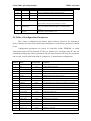
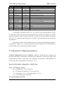
Intelligent Transmitter for Simatic S7-300 PLC
CARBO 1001
Date of Issue: 1/2009
MESA Electronic, GmbH Leitenstrasse 26, D-82538 Geretsried–Gelting, Tel.: 08171-7693-0, Fax: 08171-7693-33
E-mail: [email protected], Homepage: www.mesa-gmbh.com
Carbo1001_manual-v2-0
messen – steuern – automatisieren - messen – steuern – automatisieren - messen – steuern – automatisieren
Operating Manual
Manufacturer
MESA Electronic GmbH
Leitenstraße 26
D-82538 Geretsried-Gelting
Telephone (0 81 71) 76 93-0
Fax (0 81 71) 76 93-33
Your sales partner
About the contents
The operating manual CARBO 1001 documents structure,
measuring technique, function, and installation of the device as
well as error diagnostics.
The instructions address all users (owners) and operators of the
CARBO. It must be accessible to these persons and must be read
through carefully before using the device.
All rights to this documentation, especially the right of reproduction and distribution and
translation reserved by MESA Electronic GmbH, and for the event of copyright
applications. No part of the documentation may be reproduced or modified, copied or
distributed using electronic systems in any form without the express permission of MESA
Electronic GmbH.
Subject to errors and technical modifications.
© MESA Electronic GmbH
MESA Electronic GmbH will not be liable for any errors in this documentation. Liability
for any direct or indirect damages caused in connection with the delivery or use of this
documentation is excluded insofar as this is legally permissible.
MESA Electronic GmbH, Leitenstrasse 26, D-82538 Geretsried–Gelting, Tel.: 08171-7693-0, Fax: 08171-7693-33
E-mail: [email protected], Homepage: www.mesa-gmbh.com
Carbo1001_manual-v2-0
Carbo 1001 operating manual
MESA electronic
TABLE OF CONTENTS
1. INTRODUCTION ......................................................................................................... 2
2. INPUTS AND FUNCTIONS......................................................................................... 3
2.1 Pin assignments of X1 terminal ........................................................................................3
2.2 Inputs and Ranges .............................................................................................................3
2.3 Scope of functions ..............................................................................................................4
2.4 The Function of LED .........................................................................................................5
2.5 Table of measurement results ...........................................................................................7
2.6 Table of Configuration Parameters .................................................................................8
2.7 Explanation of configuration parameters .......................................................................9
2.8 Foil test..............................................................................................................................12
3. INSTALATION AND OPERATION INSIDE STEP 7 ................................................. 14
3.1 Software and hardware requirements ...........................................................................14
3.2. Instalation ........................................................................................................................14
3.3 Mounting the Carbo1001 ................................................................................................14
3.4 Library installation..........................................................................................................15
4. EXAMPLE PROJECT "CARBO1001_VER2_TWOCP340" ..................................... 16
5. ADDING CARBO1001 TO THE PROJECT .............................................................. 18
5.1 Configuring the Carbo1001 module inside STEP7 programming environment .......18
5.2 Open Library CarboLib1001_ver2 ................................................................................21
6. CARBO1001 FUNCTIONS AND DATA BLOCKS INSIDE STEP7 .......................... 23
6.1 Function FC300, Symbolic name "Carbo_main". .......................................................23
6.2 Function FC309, symbol name "OneCommand" ........................................................24
6.3 Function FC315, symbol name "GetMeasurement" ....................................................26
6.4 Function block FB317 symbolic name "CarboMenu" .................................................26
6.4.1 Instanced data block for function block FB317 ..................................................... 27
6.4.2 Execution of foil test via function block FB317.................................................... 29
APPENDIX .................................................................................................................... 30
A.1. STL source code of OB1 block of example project
"Carbo1001_ver2_twoCP340" .............................................................................................30
Carbo 1001 operating manual
MESA electronic
A.2. List of all blocks used in library CarboLib and example project .............................32
A.3. Table of used symbols ....................................................................................................33
A.4. Technical Data ..............................................................................................................34
Page 1 of 37
Carbo 1001 operating manual
MESA electronic
1. INTRODUCTION
The CARBO 1001 device is designed for using as an intelligent transducer in
industrial plants (hardening furnaces, heat treatment plants). Different type of sensors can
be accepted. It includes complex mathematic calculation for finding value of C
concentration, and/or others measurement results, depend on configuration. There is an
actual value correction facility.
The Carbo 1001 module can be used with SIMATIC S7-300 type of CPU. Inside
system with one CPU, up to three Carbo1001 modules can be attached. Carbo 1001 is
based on CP340 RS232C communication module and additional measurement board
included inside housing, which measures necessary signals (4 analog inputs, electrical
isolation of all channels, 16 bits).
Based on current configuration (see 2.6) there are few different transducer
functions of Carbo 1001:
C-level computer on an L-probe, an O2-probe or a CO2-analyser.
Transducer L-probe voltage
O2-probe voltage.
Computer for the quotients CO content and CO2 content (CO/CO2 level) from Lprobe voltage or O2 probe voltage or CO2 analyser and the process temperature.
Percentage of O2 concentration is calculated as float point measurement result (in
big dynamic range of result, from 10-28% to 0.21% of O2),
Dew Point calculation.
The determination of the C level from the residual oxygen and carbon monoxide
content of a furnace atmosphere and the process temperature in connection with a
conventional controller enable a low-cost system for controlling carbon atmospheres in
heat treatment plants.
Another function of the device is the conversion of the L-probe voltage into the
equivalent probe voltage of a conventional zirconium dioxide probe (O2 probe) whereby
the much more robust and lower cost L probe can be adapted to existing control systems.
Device calculate and present all possible output results according to current inputs
and configuration: temperature inside furnace, mV of O2 probe, contest of CO2, C level,
CO/CO2 ratio, Dew point in [OC], and concentration of O2 as float point result.
Automatic two point correction mechanism is provided for next outputs: L-probe
voltage to O2-probe voltage, C level, Dew Point and O2%.
Page 2 of 37
Carbo 1001 operating manual
MESA electronic
2. INPUTS AND FUNCTIONS
X1 Terminal
1 ... 9 10
G8 G6 G4 G2
G7 G5 G3 G1
Pt100
sensor
SF Tx Rx
GR R1 R2 R3
2.1 Pin assignments of X1 terminal
1. Thermoelement+
2. Thermoelement3. CO anly+
4. CO anly 5. O2/CO2 probe+
6. O2/CO2 probe7. Readiness Signal of Carbo1001 result, max 20mA, NPN-, emitter
8. Readiness Signal of Carbo1001 result, max 20mA, NPN+, collector
9. Supply +24V
10. Supply 0V
2.2 Inputs and Ranges
There are three analog input signals:
1. Probe input (X1.5 and X1.6), with three possible sources:
- L probe, range -20mV...1300mV
- O2 probe, range 0mV...1300mV
- CO2 analyzer, range 0mV...1300mV
2. CO analyzer input (X1.3 and X1.4), with range 0mV...1000mV, accept content of CO.
3. Thermoelement (X1.1 and X1.2), type S (PtRh-Pt) or K (NiCr-Ni), with range
0mV...13mV or 0mV...50mV, with cold junction compensation by Pt100 sensor in device.
4. Readiness output of Carbo1001 result (X1.7 and X1.8), NPN transistor max 20mA.
Switch-on when all inputs are in proper range, and result is ready.
Page 3 of 37
Carbo 1001 operating manual
MESA electronic
2.3 Scope of functions
1) C-level computer:
When used as a C-level computer, the C-level is calculated in furnace atmospheres
from the voltage signal of an L-probe or O2-probe or a CO2-analyser as well as the process
temperature.
The CO-content of the furnace atmosphere can be permanently set as a parameter
value. It can also be fed optionally into the CARBO as an analog signal of a CO-analyser.
The result signal can be influenced by two correction values. Since the CARBO has
been calibrated in the laboratory under ideal conditions, but the specific on-site conditions
usually deviate from these as a rule, an arithmetic correction of the measured values must
be made to adapt them to the respective conditions, and to avoid false results. These
correction data are determined typically from foil tests performed by Carbo 1001.
Analog input signals:
Probe input: One of all possible sources
L-probe
O2-probe
CO2-analyser
Thermoelement input: Thermoelement Type S or K.
CO analyzer input: CO-content, optional.
2) O2 concentration:
Concentration of O2 as float point result is calculated based on probe voltage input.
If O2 probe is used, then process temperature is required. Output result is real (float point)
number due to big dynamic range: from 10-28% to 0.21% of O2). This float point result can
be also influenced for arithmetic adaptation of the measured values to the specific
conditions of the respective plant with two correction values, which are entered via
included PLC program.
Analog input signals:
Probe input: One of possible sources
L-probe
O2-probe
Thermoelement input: Thermoelement Type S or K.
3) Dew Point:
Dew Point in [OC] is calculated based on inputs and concentration of H2, which is
entered as constant. The result signal can be influenced by two correction values.
Page 4 of 37
Carbo 1001 operating manual
MESA electronic
Analog input signals:
Probe input: One of possible sources
L-probe
O2-probe
Thermoelement input: Thermoelement Type S or K.
4) L-probe - O2 probe computer:
When used as an L-probe-O2-probe computer, the voltage signal of an L-probe is
converted into an equivalent voltage signal of a conventional zirconium dioxide probe.
The result signal (O2-probe voltage) can be influenced for arithmetic adaptation of
the measured values to the specific conditions of the respective plant with two correction
values, which are entered via included PLC program.
Analog input signals:
Probe input: L-probe voltage.
Thermoelement input: Thermoelement Type S or K.
All variants:
Digital outputs: (open collector output for 24 V=)
Standby signal, becomes inactive under each of the following conditions:
device switched off or not ready for operation
signal overflow
serious internal error occurred
2.4 The Function of LED
There are three groups of LEDs on Carbo1001:
Square LEDs on front side of housing - display current status of communication between
PLC and Carbo1001:
SF - red LED, light when there is error of CP340 communication module inside Step7.
Tx - green LED, light on message from PLC to Carbo1001
Rx - green LED, light on message from Carbo1001 to PLC
When there is no power supply for Carbo1001, then only Tx blinks. When Carbo1001
answer on message, then both Tx and Rx blinks rapidly.
Four Round LEDs on front side of housing - display current status of measurement:
GR - overall status:
flash slow GREEN when all is ok.
flash RED slow for error which is not critical
Page 5 of 37
Carbo 1001 operating manual
MESA electronic
flash RED rapid for critical error
R1 - temperature measurement:
flash slow RED for Pt100 sensor error (cold side thermoelement temperature), then
default value of 300C is used.
light RED for thermoelement error
R2 - light RED for CO probe error. Then Fix value of CO is used.
R3 - light RED on O2 probe error.
Error status Remarks:
- If GR is only RED LED, then calculation error is present. Error causes are
temperature <7500C, or calculated C level greater then 1.8%.
- IF GR is flash RED slow, then error is not critical, so some measurement results
are present.
- If GR flash rapid RED, then there is no valid measurement result.
Eight GREEN LEDs near to connector - present current setting of Carbo1001
(parameter CONFIG at address 1):
G8, G7 - CO Analyzer selector
0,0 - CO Analyzer 0..1V to 0..60% CO
0,1 - CO Analyzer 4-20mA (0.2..1V) to 0..60% CO
1,0 - CO Analyzer, 0..1V to user define range of % CO
1,1 - CO fix value, input is not used
G6 - Termoelement selection
0 - PtRh-Pt Thermoelement, S type
1 - NiCr-Ni Thermoelement, K type
G5, G4, G3 - Probe selection:
0,0,0 - L probe, -20mV to 1300mV
0,0,1 - O2 probe, -20 to 1300mV
0,1,0 - CO2 Analyzer 0.15mA..1.05mA (150mV-1050mV) to 0.03..3.000%,log scale.
0,1,1 - CO2 Analyzer 4-20mA (260mV-1300mV) to 0..0.5% lin.
1,0,0 - CO2 Analyzer 0-1300mV to 0..20% lin.
1,0,1 - CO2 Analyzer, 0-1000mV to user define range of % CO2
G2, G1 - main function of device,
0,0 - C level computer
0,1 – O2%
1,0 – Dew Point
1,1 - L probe to O2 probe computer
Page 6 of 37
Carbo 1001 operating manual
MESA electronic
2.5 Table of measurement results
The measurement results and configuration parameters for each particular zone can
be read and set via PLC program and functions calls, explained in chapter six. Here, the
tables of that measurement results and configurations are exposed to explain functionality
and correction techniques inside device.
All measurement results are integer type except status and errors, where lower byte
can be interpreted bit by bit, as exposed. Depend on configuration, some measurement
results have invalid values (0x8000 = -32768). At number 18 and 19 are status and error
byte for Carbo device.
Version number of Module firmware is at address 22.
Address
Name
Comments
1
SOND_SPG_RM
Probe voltage [0.1mV]
2
LS_SPG
L-probes voltage [0.1mV]
3
O2_SPG
O2-probes voltage [0.1mV]
4
O2_SPG_cor
O2-probes voltage, corrects [0.1mV]
5
TMPK
Temperature [OC]
6
TMP_V
Cold junction temperature [OC]
7
CO
CO content [0.1%CO]
8
CO2
CO2 content [0.001%CO2]
9
C_PEG
C level [0.01%C]
10
C_PEG_cor
C level, corrects [0.01%C]
11
C0X_PEG
CO/CO2 level [0.1]
12
Dew_Point
Dew Point [0.01 OC]
13
Dew_Point_cor
Dew Point [0.01 OC]
14:15
O2f
O2 concentration as real number (use 4 bytes=2 INT)
16:17
O2f_cor
Corrected O2 concentration as real number
18
STATUS
bit pos 0
Thermocoupler Type K=True, S=false
18
1
-reserve-
18
2
-reserve-
18
3
18
4
-reserve-
18
5
-reserve-
18
6
-reserve-
18
7
new Correction Data
0
error inside device
19
1
error of ambient temperature sensor
19
2
error of Thermocoupler input channel
19
3
error or CO-Analyser input channel
19
ERRORS:
CO value = CO fixed value
Page 7 of 37
Carbo 1001 operating manual
MESA electronic
19
4
error ...reserve...
19
5
error in calculation (range of output values)
19
6
error in Parameter internal memory
19
7
inadmissible configuration
20
FOILSTAT
Status of foiltest correction: 0-non, 1-run, 2-finish, 3abort undoc,4-forgottn,8-nonstable,16-calcerr
21
Moduletype
For Carbo1001E should be equal to 2 if INP module
exist
22
Version
Firmware version number x.xx
2.6 Table of Configuration Parameters
The CARBO is calibrated at the factory before delivery. However, the function of
device, and the correction data, whose adjust transducer to real furnace parameters, should
be set.
Configuration parameters are stored in Carbo1001 inside EEPROM, so retain
setting after power-off. By function FC309 (see chapter 6.2), and input code 'W' one can
permanently change the value of parameter. By the same function and code 'R', parameter
can be read. Actual value in the table is example for C measurement configuration.
Address
Name
Actual value
w#16#0
Comments
1.
CONFIG
Main Configuration word
2.
K1
-80
3.
K2
0
L-probe offset K2
4.
TempOfset
0
Temperature offset ['C]
5.
COfix
200
CO fix value [0.1%CO]
6.
COmin
10
minimum CO-analyser value [0.1%CO]
7.
H2fix
400
H2 fix value, used for Dew Point [0.1%H2]
8.
CO2min
9.
CO2max
10.
COmin
0
CO min value for user range of CO analyser in [0.1%]
11.
COmax
600
CO max value for user range of CO analyser in [0.1%]
12.
CorA_O2spg_TMP
-32768
Temperature for O2 correction, first point
13.
CorA_O2spg
-32768
Calculated O2, first point
14.
CorA_O2spg_cor
-32768
Corrected O2, first point
15.
CorB_O2spg_TMP
-32768
Temperature for O2 correction, second point
16.
CorB_O2spg
-32768
Calculated O2, second point
17.
CorB_O2spg_cor
-32768
Corrected O2, second point
18.
CorA_C_TMP
-32768
Temperature for C correction, first point
19.
CorA_C
-32768
Calculated C, first point
20.
CorA_C_cor
-32768
Corrected C, first point
L-probe offset K1 [0.1mV]
0
CO2 min value for user range of CO2 analyser in [0.001%]
20000
CO2 max value for user range of CO2 analyser in [0.001%]
Page 8 of 37
Carbo 1001 operating manual
MESA electronic
21.
CorB_C_TMP
-32768
Temperature for C correction, second point
22.
CorB_C
-32768
Calculated C, second point
23.
CorB_C_cor
-32768
Corrected C, second point
24.
CorA_DewP
-32768
Calculated DewPoint, first point
25.
CorA_DewP_cor
-32768
Corrected DewPoint, first point
26.
CorB_DewP
-32768
Calculated DewPoint, second point
27.
CorB_DewP_cor
-32768
Corrected DewPoint, second point
28,29
CorA_O2%f
-32768
Calculated O2% float, first point
30,31
CorA_O2%f_cor
-32768
Corrected O2% float, first point
32,33
CorB_O2%f
-32768
Calculated O2% float, second point
34,35
CorB_O2%f_cor
-32768
Corrected O2% float, second point
36
Foli_TMP
-32768
Internal
37
Foil_calcC
-32768
Internal
38
Foil_C
-32768
Internal
User should set parameter from 1 to 7. If L-probe is used, then parameters 2 and 3
are important. If there is temperature measurement error, parameter 4 should be set. If Dew
point measurement result is required then H2 fix value (7) must be defined. Parameters
from 8 to 11 is required if specific range of CO and/or CO2 input analyzer are used and set
in parameter 1.
After that, correction of any results of interest can be performed using particular 'C'
command (see chapter 6.2). Correction parameters can be changed via 'W' command also,
but with skills and recognition of parameters function.
2.7 Explanation of configuration parameters
1) Main Configuration parameter (CONFIG) at address 1 defines the type of inputs, and
the main result which correspond to calculation error indication. For the Carbo 1001E, this
configuration parameter is byte type, and completely correspond to LED diagnostic on
CPU board, when configuration is selected (see 2.2.1).
Function of bits inside configuration - CONFIG byte:
b7, b6 - CO Analyzer selector
0,0 - CO Analyzer 0..1V to 0..60% CO
0,1 - CO Analyzer 4-20mA (0.2..1V) to 0..60% CO
1,0 - CO Analyzer, 0..1V to user define range of % CO
1,1 - CO fix value, input is not used
b5 - Thermoelement selection
Page 9 of 37
Carbo 1001 operating manual
MESA electronic
0 - PtRh-Pt Thermoelement, S type
1 - NiCr-Ni Thermoelement, K type
b4, b3, b2 - Probe selection:
0,0,0 - L probe, -20mV to 1300mV
0,0,1 - O2 probe, -20 to 1300mV
0,1,0 - CO2 Analyzer 0.15mA..1.05mA (150mV-1050mV) to 0.03..3.000%,log scale.
0,1,1 - CO2 Analyzer 4-20mA (260mV-1300mV) to 0..0.5% lin.
1,0,0 - CO2 Analyzer 0-1300mV to 0..20% lin.
1,0,1 - CO2 Analyzer, 0-1000mV to user define range of % CO2
b1, b0 - main results for calculation error indication
0,0 - C level computer
0,1 – O2%
1,0 – Dew Point
1,1 - L probe to O2 probe computer
Example: CONFIG = W#16#00C0 = 192, defines that C level computer will be based on
fix CO value, S type thermoelement and L probe.
2) Probe K parameters:
The K1 is stored at address=2. This value is a probe-specific parameter which must
be re-entered when the L-probe is changed.
The K2 is stored at address=3. This value is a probe-specific parameter which must
be re-entered when the L-probe is changed.
3) Temperature measurement correction:
Parameter TempOfset (address 4) temperature offset correction is used to
optionally correct thermocouple temperature measurement by adding entered value to final
temperature measurement results. Before that final correction, linearization and cold
junction compensation is performed, depending on selected thermocouple type.
4) COfix value [0.1% CO] is integer value at address 5. If there is no CO-analyzer
connected to the input, this fix value is used to calculate main measurement results (C
value) of transducer. If there is some error of CO input, this value is used also, and notcritical error is reported via R2 status LED. Default value is 200, i.e. 20.0% of CO. In the
Main configuration word, user can select force using of fix CO value instead of using
measured value. COmin parameter (address 6) is used to define lower limit of valid CO
value. Both parameters as all others are also settable for each particular zone.
5) H2fix value [0.1% H2] is integer value at address 7. Concentration of H2 is used only
for Dew Point calculation.
6) CO2min and CO2max (address 8 and 9), integer number with [0.001% CO2]
resolution are used if user defined range of CO2 analyzer is selected in CONFIG
Page 10 of 37
Carbo 1001 operating manual
MESA electronic
parameter. 0-1000mV of input voltage is transferred to CO2min-CO2max range of CO2%
concentration.
7) COmin and COmax (address 10 and 11), integer number with [0.1% CO] resolution are
used if user defined range of CO analyzer is selected in CONFIG parameter. 0-1000mV of
input voltage is transferred to COmin-COmax range of CO% concentration.
When used as an L-probe-O2-probe computer, the voltage signal of an L-probe is
converted into an equivalent voltage signal of a conventional zirconium dioxide probe.
8) Correction of measurement results
Two point correction mechanism is provided for next measurement results: 1) Lprobe voltage to O2-probe voltage (after correction results are O2_SPG_cor in
measurement list), 2) C level (C_PEG_cor), 3) Dew Point (DewPoint_cor) and 5) O2%
(O2f_cor).
For O2 probe voltage, and C level measurement results, temperature dependent
corrections are implemented. For all corrections it is possible to use particular „C‟
command to enter right value of measurement (see chapter 6.2), where device itself
chooses right correction point (CORRA or CORRB) to change, and sets temperature,
measured and correction values. Another possibility is to change temperature, calculated
and corrected value in parameter list directly.
The following rules must be observed when manually overwriting those data:
- The data must be within the value range (working area) - There is no plausibility
check!
- Particular correction point can be deleted by overwriting parameters with invalid
value (8000hex = -32768dec).
- If only one valid correction set is to be entered, this must be at CORRA whilst
CORRB is invalid.
For temperature dependent correction:
- If both sets are occupied, the set with the lowest temperature must be at
CORRA.
- The difference between the temperatures of both correction sets must be
more than 30 degrees.
Those rules are observed automatically by the program when entering a correction
set by „C‟ command, see chapter 6.
Both correction points for one measurement results, or for all results, can be erased
simultaneously via „C‟ commands, also.
"L-probe voltage to O2 voltage transducer" correction parameters (integer parameters at
addresses from 12 to 17). Device calculates mV of conventional O2 as O2_SPG
Page 11 of 37
Carbo 1001 operating manual
MESA electronic
measurement result. Corrected value (O2_SPG_cor measurement result) is calculated
based on two optional correction points, at two different temperatures. Correction can be
set by entering known C level values (perform one command, adr=5, see chapter 6.2). Both
correction points can be erased by one command, adr=6.
C level correction parameters (integer parameters at addresses from 18 to 23). Device
calculates C% level as C_PEG measurement result. Corrected value (C_PEG_cor
measurement result) is calculated based on two optional correction points, at two different
temperatures. Correction can be set by entering known C level values (perform one
command, adr=11, see chapter 6.2), or by performing foil test explained in next chapter.
Both correction points can be erased by one command, adr=12.
Dew Point correction parameters (integer parameters at addresses from 24 to 27). Device
calculates Dew Point as Dew_Point measurement result. Corrected value (Dew_Point_cor
measurement result) is calculated based on two optional correction points. Correction can
be set by entering known Dew Point values (perform one command, adr=7, see chapter
6.2). Both correction points can be erased by one command, adr=8.
O2% correction parameters (float point parameters – each occupy two integer places in list
of paramteres at addresses from 28:29 to 34:35). Device calculates concentration of O2 as
float point O2f measurement result. Corrected value (O2f _cor measurement result) is
calculated based on two optional float point correction points. Correction can be set by
entering known O2f values (perform one command, adr=9, see chapter 6.2). Both
correction points can be erased by one command, adr=10.
2.8 Foil test
Instead of directly changing C-level measurement correction parameters, device
and delivered PLC software provide automatic performing of foil test. Foil test can be start,
stop or cancel for more than one zone independently from each other.
For one particular zone, user should start foil test via FC309 or FB317, perform one
command, adr=14. please see chapter 6.2 and 6.4.2. During foil test, device check integrity
of measurement results and device status in order to reject false correction. After
successful start of foil test, user can watch on foilstat value (measurement results table,
address 17). During execution of foil test, foilstat has value 1.
At the beginning and during foil test next checking is performed:
- Foiltest must run more then 60 sec, if not foilstat=8.
- Temperature must be >750OC, and C>0,1%. Opposite foilstat=8.
- If calculated C values are changed for more than 0.2%, then foilstat=8, also.
Page 12 of 37
Carbo 1001 operating manual
MESA electronic
- If there is any error in Carbo calculation so there is no valid C value (any input or
calculation results are out of measurement span of device), then foilstat=16.
- Foil test is considered forgotten, when didn't stop for 30 minutes (foilstat=4)
Foil test must be stopped in 30 minutes. (perform one command, adr=15) If test has
finished well, foilstat will be =2. The results of foil test are temporary written inside
configuration parameters. After that, user can enter real value of C level which was stable
during foil test, using function FC309, address=13, or FB317. User can erase performed
foil test instead, using FC309, address=16.
The results of entering correct C value will be new correction point (CORRA or
CORRB). After successful correction, foilstat becomes zero again.
Page 13 of 37
Carbo 1001 operating manual
MESA electronic
3. INSTALATION AND OPERATION INSIDE STEP 7
3.1 Software and hardware requirements
Software requirements:
1. An installed version of STEP 7 Basis V4.02 or higher.
Hardware requirements:
1. S7-300 mounting rack (DIN rail).
2. Power supply from PS-300 series.
3. CPU 31x module from SIMATIC S7-300 series.
4. Memory card with 64KB, or more, is recommended.
5. MPI-USB or MPI-RS232 adapter for connection with PC, (e.g. PG 740).
6. Standard PC.
3.2. Instalation
Before using Carbo1001 in your control application you will need to perform the
following operations in the given order:
1. Mounting the Carbo1001.
2. Library installation.
3. Configuring the Carbo1001.
4. Creating a user program for the Carbo1001, or adding it in existing application.
3.3 Mounting the Carbo1001
The following section describes the rules that you must observe when positioning
the Carbo1001 in the rack.
For mounting and demounting the Carbo1001 you require a 4.5mm cylindrical
screwdriver.
To insert the Carbo1001 in a rack, proceed as follows:
1. Switch off the CPU by POWER OFF power supply unit.
2. The Carbo1001 is accompanied by an extension bus. Plug this onto the
backplane connector of the module to the left of the Carbo1001.
3. If more modules are to be mounted to the right, plug the expansion bus of the
next module onto the right backplane connector of the Carbo1001.
4. Mount the Carbo1001 on the rail and tilt it downward.
5. Screw the Carbo1001 tight.
6. Connect 24V power supply to Carbo 1001 from power supply unit (PS-300
series).
7. Connect all necessary probes.
Page 14 of 37
Carbo 1001 operating manual
MESA electronic
3.4 Library installation
In order to be able to work with the Carbo1001 library you need to have installed Point-toPoint Communication (CP PtP Param) package which comes with CP340 module. It
contains all necessary driver files and library to work with CP340 module. If you don't
have installed CP PtP Param package follow this instruction:
The CP configuration software can only be installed once STEP 7 has been
completely installed.
Before starting the Setup program, close all other applications (such as STEP 7,
MS Word, etc.).
Insert CD in the drive and start the Setup program in the Setup folder. The files
are then copied to the PC/programming device and the appropriate entries are
made in the MS Windows files. Important information on handling will be
displayed during the Setup process.
The drive on which you install the software for the CP configuration is
automatically determined with the installed version of STEP 7.
In order to remove the program use the functions in the Control Panel >
Add/Remove Programs function. STEP7 cannot be removed unless all the option
packages have been removed.
Next install Carbo1001 library as described below:
Copy "CarboLib1001_ver2" folder from installation CD to folder
\Siemens\Step7\S7LIBS\
Copy Example project "Carbo1001_ver2" from installation CD to folder
\Siemens\Step7\S7Proj\
Page 15 of 37
Carbo 1001 operating manual
MESA electronic
4. EXAMPLE PROJECT "Carbo1001_ver2_twoCP340"
There are two approach of software start-up of Carbo 1001:
1) To use example project "Carbo1001_ver2_twoCP340", and then you can adjust
hardware configuration from used CPU312C to actually used CPU.
2) To create new project and then to insert CP340 module to hardware configuration of
project following instruction in next chapter, and all required block from library
"CarboLib1001_ver2".
Example project is easier way for starting up. It explains standard functions for
operating the Carbo 1001 modules. There is example program based on two Carbo1001
modules. Inside the example project CPU312C is used, CP340-RS232C module is installed
in slot 4 and 5, and configured as Carbo1001 requires. If this setting is not ok, please see
hardware configuration of CP340 in next chapter. If you use one Carbo1001 module,
please disable/delete part of OB1 which calls second module, and change the address of
module to zero, defined in calling of FC300.
Instruction:
Open the project using the STEP 7 SIMATIC Manager by calling the menu
command File > Open > Project.
Check that the hardware for the example is fully set up and programming device is
connected. Transfer the complete code to the user memory. After the overall reset of the
CPU (operation mode STOP), use the operating mode switch to change from STOP to
RUN mode. User just needs to switch button Monitor ON/OFF for observed block in order
to see actual values of measurement results.
Cyclic execution of Program
Example program is present in appendix A.1. The cyclic program execution is
defined in the organization block OB1. The main function block is FC300 "Carbo main". It
is placed in one network and executed cyclic. First three input parameters for FC300 call
defines the addresses of attached Carbo modules. If there is only one module, then only
first address is non zero. The last parameter is PREV_CYCLE, which takes value of
OB1_PREV_CYCLE temp parameter for OB1 process as time reference. Inside FC300 is
functionality of transferring measurements results and configuration parameter for
Carbo1001 device. Please see chapter 6.1.
Page 16 of 37
Carbo 1001 operating manual
MESA electronic
Carbo1001 modules are used via function block FB317, with instanced data blocks
DB307 and DB308 (for two modules). Changing variables (programmaticaly, or by
debugger) inside that data blocks, user can start particular commands, or can choose
automatical transfer of all measurement results.
In the example, disabled part of code with function FC315, "GetMain value",
which obtains main measuremetn results automatically, can be seen. Depend on
configuration, main measurement results can be for example C value in [0.01%]. Each new
measurement result and correctness of the result is used to drive digital output A124.3 i
A124.1. Measurement value of C is transfered to CVAL variable inside OB1, and used to
compare with defined constant value.
Page 17 of 37
Carbo 1001 operating manual
MESA electronic
5. ADDING CARBO1001 TO THE PROJECT
Setting described in this chapter is required if you use Library instead to modify
example program.
5.1 Configuring the Carbo1001 module inside STEP7 programming
environment
Once you have mounted the Carbo1001 module you must inform the
programmable controller that it is there. Before you can enter the Carbo1001 in the
configuration table of the STEP7 software, you must have created a project and a terminal
with STEP7. Then, follow steps bellow:
Click SIMATIC 300 Station folder in your project. All the hardware-related
project data are stored here. Open the SIMATIC 300 Station folder and double-click the
Hardware symbol.
The "HW Config" window opens. The CPU you selected on creating the project is
displayed.
Page 18 of 37
Carbo 1001 operating manual
MESA electronic
Navigate in the catalogue until you reach the CP 340 RS232C module and drag
and drop this onto one of allowable slots (green fields). Repeat adding CP340 for each
used Carbo module.
Double-click to CP 340 RS232C modules field to open properties.
In addresses tab one can define input and output address of the module. Carbo 1001
program and Library use the same addresses for both start fields of the one particular
module. If more than one Carbo module is installed, then all modules have the same
properties according communication protocol, but in the address tab of properties window,
addresses of each existing module must be different. When FC300 - Carbo_main function
Page 19 of 37
Carbo 1001 operating manual
MESA electronic
(please see chapter 6.1) is called, one must define actual addresses of all used modules.
The address must be set to zero, if module is not used. Next table present default address
during configuration of CP340 modules.
Module number:
Input/output start addresses:
1
256
2
272
3
288
Click on Parameter button.
Choose ASCII type of communication form Protocol drop menu and click on
Protocol box (blue) to set communication parameters.
Choose value for Speed and Character Frame:
- Transmission Rate: 9600
- Data Bits: 7
- Stop Bits: 2
- Parity: Even
For End Code of a Receive Message Frame choose On Receipt of End
Character(s).
Character Delay Time set to 9 ms.
- 1st End ID: [Hex] 2A
- 2nd End ID: [Hex] 0D
Page 20 of 37
Carbo 1001 operating manual
MESA electronic
Then click on OK button.
Click on Save and Compile icon to confirm setup.
5.2 Open Library CarboLib1001_ver2
It is important to say that user needs to copy all DBs, FBs and FCs from library
CarboLib to opened project. Then it is easy to call all relevant functions in user program
and watch results in appropriate DBs.
To copy all DBs, FBs and FCs from library CarboLib to user program you need to
open library "CarboLib" in SIMATIC manager, select all blocks and click on right button
Page 21 of 37
Carbo 1001 operating manual
MESA electronic
of mouse and choose Copy command. Then go to your project and in block section where
OB1 block is, and paste blocks with click on right button mouse and use Paste command.
After that, functionality of Carbo device is reached if at least FC300 "Carbo main"
function is cyclic called, for example inside OB1 block, see chapter 6.
Page 22 of 37
Carbo 1001 operating manual
MESA electronic
6. CARBO1001 FUNCTIONS AND DATA BLOCKS INSIDE
STEP7
Communication between the CPU and the Carbo1001 takes place via cyclic
execution of FC300 (for example in OB1). There are few different approaches of using
Carbo software:
1) Low level approach is to use only FC309 function with different parameters to
reach all functionality of Carbo device (chapter 6.2)
2) Another approach is to use function block “CarboMenu” - FB317, and instanced
data blocks per each zone (DB307 and DB308 in example, please see chapter 6.4). This is
procedure, which cyclic obtain all measurement results and perform other command on
user request, or change parameters, as some kind of terminal program. Here, user should
only read and write variables from instanced data blocks DB307 and DB308.
3) If parameters and correction are set, one can use only function
"GetMeasurement" - FC315 to obtain one particular measurement results, and the pulse
when each new measurement results arrived. This approach requires less memory than 2).
At one time, only one function of FC309, FC315 or FB317 can be used for one
particular zone of Carbo1001E, but FC300 is required once for all zones together.
Functions from FC301 to FC307 are not called directly. Please see appendix A.2 for all
function block and overall required program resources.
6.1 Function FC300, Symbolic name "Carbo_main".
This is main loop function, which automatic sends and receives all required
message between PLC and all Carbo 1001 device. It calls timer and CP340 send/receive
functions, and must be used in cyclic program one for all installed Carbo modules. Input
variable PREV_CYCLE CYCLE takes value of OB1_PREV_CYCLE temp parameter for
OB1 process. Input variable adr1..adr3 is address of Carbo 1001 modules attached into the
system.
The same Simatic software is used for this Carbo1001E type of device, and for
Carbo1001 devices. Only different is in calling FC300:
1) Carbo1001: it is possible to attach up to three Carbo1001 devices to system,
and each must have different address (adr2 is different from adr1, etc).
2) Carbo1001E: it is possible to attach only one Carbo1001E device with one
ore more input modules, so only adr1 is used, and must not be zero.
Input/output parameters:
Page 23 of 37
Carbo 1001 operating manual
Name
adr1
adr2
adr3
Carbo1001E
PREV_CYCLE
Type
INPUT
INPUT
INPUT
INPUT
INPUT
Data type
INT
INT
INT
BOOL
INT
MESA electronic
Description
Address of used module, default is 256
Address of second used module, default is 272
Address of third used module, default is 288
True for Carbo1001E, false for Carbo1001
OB1_PREV_CYCLE, must be used for timer
6.2 Function FC309, symbol name "OneCommand"
Implement one command for communication with particular zone (module)
Carbo1001. If there is more than one zone, then one can use only one FC309 for each
particular zone in parallel.
Depend of the input code, there are next actions:
'M' - read one measurement results defined by address. Please see chapter 2.5 for the
table of enumerated all possible measurement results.
'R' - read one configuration parameter defined by address. Please see chapter 2.6 for
the list of parameters.
'W' - write one configuration parameter defined by address.
'C' - perform one command. Code of command is in address variable, with meaning:
Address=1, execute software reset of Carbo 1001 device - make influence on all zones,
no matter on which is performed. In general, there is no need to manually
reset device. Resetting is performed very quickly, only some pause in LED
working can discover that this command is executed.
Address=2, then EnterVal contain new Cofix value. This value is used when it is defined so in configuration, but also when CO input value is not correct (see 2.7).
Address=3, then EnterVal contain new H2fix value. This value is used for DewPoint
caculation.
Address=4, clear all correction points for all measurement results whose are corrected.
Address=5, then EnterVal contain new O2 mV correction value. Function performs
adding new correction point for L mV to O2 mV conversion (see 2.7).
Address=6, clear both correction points for O2 mV.
Address=7, then EnterVal contain new Dew Point correction value. Function performs
adding new correction point for Dew Point measurement result (see 2.7).
Address=8, clear both correction points for Dew Point.
Address=9, then EnterVal contain upper part of O2% float point correction value as
integer number. After this device excepted second part of this float point
number through command with address 109.
Address=109, then EnterVal contain lower part of O2% float point correction value
as integer number. This command must be after one with address=9, when
first part of this float point number is received.
Address=10, clear both correction points for O2% float point calculation.
Page 24 of 37
Carbo 1001 operating manual
MESA electronic
Address=11, then EnterVal contain new C level correction value. Function performs adding
new correction point for C level correction measurement result (see 2.7).
Address=12, clear both correction points for C level measurement.
Address=13, then EnterVal contain real C value after foil test. Function performs
adding new correction point for C measurement, if Foil test is performed
already (see 2.8).
Address=14, execute start of Foil test for particular zone, then status of foil test can be
seen with 'M' command and address 14 - Foilstat.
Address=15, execute stop of Foil test of that zone, then status of foil test can be seen
with 'M' command and address 14 - Foilstat.
Address=16, clear results of last performed Foil Test. When new corrected value of C
is not entered jet, but user want to omit last foil test and to perform new one,
then last and not used results of foil test must be erased first. That data are
cleared when correction is executed, also.
'S' - read one particular char form LOGO strings. There are 4 strings with 16 chars
with zero end char, so address can be from 0 to 68.
Input/output parameters:
Name
Type
Data type
Description
zone
INPUT
INT
start
INPUT
BOOL
Start change on rising edge of this signal
Code
INPUT
CHAR
What to do: 'M', 'R', 'W', 'C', 'S'
Address
INPUT
INT
Address of variable
EnterVal
INPUT
INT
Input Value for addressed variable or command
Outcode
OUTPUT
CHAR
Outaddress
OUTPUT
INT
Received address
OutVal
OUTPUT
INT
Read variable if any
finish
OUTPUT
BOOL
status
OUTPUT
INT
zone number, from 1 to 5
Received code of command
Become true when command is finished
Status of finished command, 0-not finished, 1good, >1 for error
Each command return "status" variable with one of the next value:
0 - Command is successful
2 - there is no answer
3 - bad command
4 - bad address of command
5 - bad value
Page 25 of 37
Carbo 1001 operating manual
MESA electronic
7 - bad zone number
8 - impossible correction or foil test
9 - command for CPU module is not allowed
15 - error during reading EEPROM
6.3 Function FC315, symbol name "GetMeasurement"
Function returns INT value of the selected measurement result for selected zone.
Communication starts itself as soon as last transfer is finished. "gotnew" signal pulse on
each new value.
Input/output parameters:
Name
Type
Data type
Description
zoneNumber
INPUT
INT
zone number, from 1 to 5
MeasNumber
INPUT
INT
From 1 to 21, select one result according to
list of measurement results
OutVal
OUTPUT
INT
integer value of main measurement result
gotnew
OUTPUT
BOOL
pulse when new measurements are obtained
good
OUTPUT
BOOL
status of the measurement results
6.4 Function block FB317 symbolic name "CarboMenu"
This Function block can be included in cyclic part of the main PLC program, for
example in OB1. For each particular zone, separate calling of FB317, with its own
instanced DB should be used. In example program, DB307 is instanced for using with zone
module number 1, and DB308 for second zone. The purpose of FB317 is to get all
measurement, and to enable calling of command function by editing static variable in
instanced data block (chapter 6.4.1). It is convenient for testing and adjusting of device,
even without additional Human Interface program, i.e. using only Step7 development
environment.
"Request_code" variable at address 84 defines next action. When code is zero, i.e.
there is no special request, then cyclic transfers of all measurement variables from device
to instanced data block are performed. When one enter some different form zero to the
"Request_code" next action is performed, and code is immediate change back to zero to
prevent multiple execution of the same action. There are all possible actions, depend of
"Request_code" variable:
0 - cyclic transfer of measurement results. After all measurement results are
transferred, "Cycle_completed" flag is pulsed.
1 - perform one 'C' command, please see chapter 6.2 for detailed explanation.
Before entering value '1' to "Request_code" variable, one should enter code of command to
"Addressinp" variable (possible codes are 1-Cofix, 2-O2corr, 3-Foil C, 4-ClrFoil, 5-clear
Page 26 of 37
Carbo 1001 operating manual
MESA electronic
corr points, 6-Reset, 7-StartFoil, 8-StopFoil, 9-H2fix), and required value to "Valinp", if
command expect input values (for changing Cofix value, O2corr and Foil correction of C
measurement value).
2 - write one parameter. Only one parameter will be transferred to EEPROM
memory, based on ordinal number of parameters in "Addressinp", and value to send in
correspond parameter variable. For example for changing main configuration word "PAR.CONFIG", one should enter "addressinp":=1; and then "Request_code":=2. After
that, current value from "PAR.CONFIG" location (address 32.0), will be transferred to
EEPROM memory.
3 - write ALL parameters. When "Request_code":=3, all current value of
parameters variable in instanced data block for that zone will be transferred to the
EEPROM of device.
4 - read ALL parameters for one zone. It is convenience to read all parameters first,
then to change few of them, and after that to write all back with "3" to the "Request_code".
When one particular request is finished, "Request_completed" variable becomes
true. If request is reading or writing parameters, then "RW_good" variable becomes false,
if there is some error during that transfer.
Input parameter:
Name
Type
Data type
zoneNumber
INPUT
INT
Description
zone number, from 1 to 5
6.4.1 Instanced data block for function block FB317
Address
in DB
Addres in
Measure or
Parametar
list
0.0
Name
zoneNumbers
2.0
Type
Initial
value
INT
0
Carbo1000 zone, i.e. module, from 1 TO 5
INT
0
Not used
Comment
4.0
1
MES.SOND_SPG
INT
-32768
Probe voltage [0.1mV]
6.0
2
MES.LS_SPG
INT
-32768
L-probes voltage [0.1mV]
8.0
3
MES.O2_SPG
INT
-32768
O2-probes voltage [0.1mV]
10.0
4
MES.O2_SPG_cor
INT
-32768
O2-probes voltage, corrects [0.1mV]
12.0
5
MES.TMPK
INT
-32768
Temperature [OC]
14.0
6
MES.TMP_V
INT
-32768
Cold junction temperature [OC]
16.0
7
MES.CO
INT
-32768
CO content [0.1%CO]
18.0
8
MES.CO2
INT
-32768
CO2 content [0.001%CO2]
20.0
9
MES.C_PEG
INT
-32768
C level [0.01%C]
22.0
10
MES.C_PEG_cor
INT
-32768
C level, corrects [0.01%C]
24.0
11
MES.C0X_PEG
INT
-32768
CO/CO2 level [0.1]
26.0
12
MES.DewPoint
INT
-32768
DewPoint [0,01OC]
Page 27 of 37
Carbo 1001 operating manual
MESA electronic
MES.DewPoint_cor
INT
-32768
DewPoint corrected [0,01OC]
14, 15
MES.O2f
Float
0.0e+0
O2[%], float point result
34.0
16, 17
MES.O2f_cor
Float
0.0e+0
O2[%] corrected, float point result
38.0
18
MES.STATUS
WORD
w#16#0
Status of device
40.0
19
MES.ERRORS
WORD
w#16#0
Error status of device
42.0
20
MES.FOILSTAT
INT
0
28.0
13
30.0
Status of foil testing: 0-non, 1-run, 2-finish, 3-abort
undoc,4-forgottn, 8-nonstable,16-calcerr
44.0
21
MES.MODULETYPE
INT
0
For Carbo input module must be =2, if no, there is no
correct module!
46.0
22
MES.Version
INT
0
Version of Module firmware
48.0
INT
0
Not used
50.0
INT
0
Not used
WORD
w#16#0
Main Configuration word
52.0
28.
PAR.CONFIG
54.0
29.
PAR.K1
INT
-32768
L-probe offset K1
56.0
30.
PAR.K2
INT
-32768
L-probe offset K2
58.0
31.
PAR.TempOfset
INT
-32768
Temperature offset ['C]
60.0
32.
PAR. COfix
INT
-32768
CO fix value [0.1%CO]
62.0
33.
PAR. COmin
INT
-32768
minimum CO-analyser value [0.1%CO]
64.0
34.
PAR. H2fix
INT
-32768
H2 fix value, used for Dew Point [0.1%H2]
66.0
35.
PAR. CO2min
INT
-32768
CO2 min value for user range of CO2 analyser in [0.001%]
68.0
36.
PAR. CO2max
INT
-32768
CO2 max value for user range of CO2 analyser in [0.001%]
70.0
37.
PAR. COmin
INT
-32768
CO min value for user range of CO analyser in [0.1%]
72.0
38.
PAR. COmax
INT
-32768
CO max value for user range of CO analyser in [0.1%]
74.0
39.
PAR.CorA_O2spg_TMP
INT
-32768
Temperature for O2 correction, first point
76.0
40.
PAR.CorA_O2spg
INT
-32768
Calculated O2, first point
78.0
41.
PAR.CorA_O2spg_cor
INT
-32768
Corrected O2, first point
80.0
42.
PAR.CorB_O2spg_TMP
INT
-32768
Temperature for O2 correction, second point
82.0
43.
PAR.CorB_O2spg
INT
-32768
Calculated O2, second point
84.0
44.
PAR.CorB_O2spg_cor
INT
-32768
Corrected O2, second point
86.0
45.
PAR.CorA_C_TMP
INT
-32768
Temperature for C correction, first point
88.0
46.
PAR.CorA_C
INT
-32768
Calculated C, first point
90.0
47.
PAR.CorA_C_cor
INT
-32768
Corrected C, first point
92.0
48.
PAR.CorB_C_TMP
INT
-32768
Temperature for C correction, second point
94.0
49.
PAR.CorB_C
INT
-32768
Calculated C, second point
96.0
50.
PAR.CorB_C_cor
INT
-32768
Corrected C, second point
98.0
51.
PAR.CorA_DewP
INT
-32768
Calculated DewPoint, first point
100.0
52.
PAR.CorA_DewP_cor
INT
-32768
Corrected DewPoint, first point
102.0
53.
PAR.CorB_DewP
INT
-32768
Calculated DewPoint, second point
104.0
54.
PAR.CorB_DewP_cor
INT
-32768
Corrected DewPoint, second point
106.0
28,29
PAR.CorA_O2%f
Float
-32768
Calculated O2% float, first point
110.0
30,31
PAR.CorA_O2%f_cor
Float
-32768
Corrected O2% float, first point
114.0
32,33
PAR.CorB_O2%f
Float
-32768
Calculated O2% float, second point
118.0
34,35
PAR.CorB_O2%f_cor
Float
-32768
Corrected O2% float, second point
122.0
36
PAR.Foli_TMP
INT
-32768
Internal
Page 28 of 37
Carbo 1001 operating manual
MESA electronic
124.0
37
PAR.Foil_calcC
INT
-32768
Internal
126.0
38
PAR.Foil_C
INT
-32768
Internal
128.0
INT
0
Not used
130.0
INT
0
Not used
132.0
INT
0
Not used
134.0
INT
0
Not used
136.0
Cycle_completed
BOOL
False
Pulse at each complete loop of reading all measurements
136.1
Request_completed
BOOL
False
true when finish requesting
136.2
RW_good
BOOL
False
become false, when some read/write of param. is not ok.
138.0
Request_code
INT
4
request : 0-automeas,1-one command,2-write one par,
3-write ALL par,4-read ALL par
140.0
Addressinp
INT
0
142.0
Valinp
INT
0
for command: 1-Reset device, 2-Cofix, 3-H2fix,
4-clear All corr points, 5-O2corr, 6-Clear O2corr,
7-DewPointcorr, 8-Clear DewPointcorr, 9-O2% Float
point corr, 10- Clear O2% Float point corr,
11-C% corr, 12-Clear C% corr, 13-Foil C%, 14StartFoil, 15-StopFoil, 16-Clear Foil,
input value for command, for example Foil C correct.
value
144.0
Valinpf
Float
0
Float input value for O2% Correction command
148.0
valout
INT
0
output variable, when some is reading
150.0
Statusout
INT
0
status of the last command
152.0
addressout
INT
0
out address data of the last command
154.0
ccount
INT
0
Internal
156.0
parcount
INT
0
Internal
158.0
command_State
INT
0
Internal
160.0
command_executed
INT
0
Internal
6.4.2 Execution of foil test via function block FB317
1) Please start foil test with: addressinp=14, and then Request_code=1. After that, please
monitor "MES.FOILSTAT" measurement value on DB address 42. During regular foil test,
this value should be =1, (Foilstat: 0-non, 1-run, 2-finish, 3-abort undoc, 4-forgottn, 8nonstable, 16-calcerr). One can also monitor main measurement value, or level of C on
address 2.
2) In next 30 minutest foil test should be stopped by: addressinp=15, and then
Request_code=1.
3) If foil test is regular finished, then MES.FOILSTAT=2. After that, one can enter
corrected C value by addressinp=3, Valinp=corrected_carbo_value, and after that
Request_code=1. Immediately, new correction becomes active.
If foil test which should be ignored before performing new one, please erase it via
addressinp=4 command. If correction performed already, but it is not good, one can erase
both correction point by, addressinp=5 and Request_code=1.
Page 29 of 37
Carbo 1001 operating manual
MESA electronic
APPENDIX
A.1. STL source code of OB1 block of example project
"Carbo1001_ver2_twoCP340"
Name
Data type
TEMP
Address
Comment
0.0
OB1_EV_CLASS
Byte
0.0
Bits 0-3 = 1 (Coming evant), Bits 4-7 = 1 (Evant
class 1)
OB1_SCAN_1
Byte
1.0
1 (Cold restart scan 1 of OB1), 3 (Scan 2-n of OB1)
OB1_PRIORITY
Byte
2.0
Priority of OB Execution
OB1_OB_NUMBR
Byte
3.0
1 (Organization block 1, OB1)
OB1_RESERVED_1
Byte
4.0
Reserved for system
OB1_RESERVED_2
Byte
5.0
Reserved for system
OB1_PREV_CYCLE
Int
6.0
Cycle time of previous OB1 scan (milliseconds)
OB1_MIN_CYCLE
Int
8.0
Minimum cycle time of OB1 (milliseconds)
OB1_MAX_CYCLE
Int
10.0
Maximum cycle time of OB1 (milliseconds)
OB1_DATE_TIME
Date_And_Time
12.0
Date and time OB1 started
Cval
Int
20.0
Block: OB1
"Main Program Sweep (Cycle)"
Example of calling CARBO1001 main procedure and some user actions
Network: 1
Calling of the main procedure of CARBO1001, must exist in OB1 !!!
CALL "Carbo main"
adr1
:=256
adr2
:=272
adr3
:=0
Carbo1001E:=FALSE
PREV_CYCLE :=#OB1_PREV_CYCLE
Network: 2
Call menu procedure by editing static variable in data blok.
Convinian for testing via Step7 upload of data blok to PLC
cycle measurement of all variable, or one particular variable can be choosen
CALL "CarboMenu" , DB307
Page 30 of 37
Carbo 1001 operating manual
MESA electronic
zoneNumber:=1
Network: 3
Call menu procedure by editing static variable in data blok.
Convinian for testing via Step7 upload of data blok to PLC
cycle measurement of all variable, or one particular variable can be choosen
CALL "CarboMenu" , DB308
zoneNumber:=2
Network: 4
Reading of Corrected C value, gotnew pulse on each complete cycle of
measurements to LED. Overall status is also obtained and sent to LED
// CALL "GetMeasurement"
// zoneNumber:=1
// MeasNumber:=9
// gotnew :=Q124.3
// good :=Q124.1
// OutVal :=#Cval
Network: 5
Example: comparation of C meas. result with fixed value in order to control
some. LED is driven
// L 18
// comparasion with 0.18% of C
// L #Cval
// >I
// compare 18>Cval
// = Q 125.5
// output result to LED
Page 31 of 37
Carbo 1001 operating manual
MESA electronic
A.2. List of all blocks used in library CarboLib and example project
Object name
Symbolic name
Size in the work
Type
memory
Obligation
use
OB1
Cycle Execution
FB2
P_RCV
1888
FB
●
FB3
P_SEND
1590
FB
●
FB317
CarboMenu
1322
FB
FC300
Carbo Main
1274
FC
●
FC301
Make_string_command
690
FC
●
FC302
Analyse_command
848
FC
●
FC303
BYTE_TO_HEXA1
90
FC
●
FC304
XORSTRING
194
FC
●
FC305
readHEXAbyte
258
FC
●
FC306
BYTE_TO_HEXA2
98
FC
●
FC307
nibble_TO_HEXA
112
FC
●
FC308
adr_CP340
136
FC
●
FC309
OneCommand
344
FC
●
FC315
GetMeasurement
274
FC
UDT300
Optional use
188
---
Org. block
for example
●
●
Data type
●
DB300
168
Data Block
●
DB301
108
Instance DB
●
DB302
104
Instance DB
●
DB307
196
Instance DB
for example
DB308
196
Instance DB
for example
SFB52
RDREC
---
System FB
●
SFB53
WRREC
---
System FB
●
SFC24
TEST_DB
---
System FC
●
SFC64
TIME_TCK
---
System FC
●
Page 32 of 37
Carbo 1001 operating manual
MESA electronic
A.3. Table of used symbols
Symbol
Address
Comments
Cycle Execution
OB
Example program
UDTcarboMain
UDT 300
Definition of data for working with Carbo
DBcarbo
DB
300
Main data block for working with all three Carbo modules
DBcomm1R
DB
301
Used from CP340 for receiving, first Carbo module
DBcomm1T
DB
302
Used from CP340 for transmiting, first Carbo module
P_RCV
FB
2
Receive Data from CP340
P_SEND
FB
3
Send Data to CP340
CarboMenu
FB
317
optional used for callcommands by editing static variable in data blok
Carbo_main
FC
300
Perform cycle execution of Carbo1001E communication
Make_string_command
FC
301
Prepare command for sending from CP340 to Carbo1001E
Analyze_command
FC
302
Analyze of receiving command
BYTE_TO_HEXA1
FC
303
Convert byte to first char of HEXA ASCII string
XORSTRING
FC
304
calculate XOR of string
readHEXAbyte
FC
305
Convert two HEXa ASCII CHARS to one byte from receive array of chars
BYTE_TO_HEXA2
FC
306
Convert byte to first char of HEXA ASCII string
nibble_TO_HEXA
FC
307
convert nibble to HEXA char
adr_CP340
FC
308
define current addres to work with CP340
OneCommand
FC
309
change either CO fix value, O2 correction, or enter Foil C value
GetMeasurement
FC
315
get one measurement result, according to inputaddress
RDREC
SFB
52
Read a Process Data Record
WRREC
SFB
53
Write a Process Data Record
TEST_DB
SFC
24
Test Data Block
TIME_TCK
SFC
64
Read the System Time
1
Page 33 of 37
Carbo 1001 operating manual
MESA electronic
A.4. Technical Data
Housing:
Siemens Simatic S7 compatible housing for Simatic Rail
mounting
Dimensions:
40 x 125 x 120 mm (BxHxT)
Weight:
ca. 0.4 kg
Degree of protection:
IP 20 according to DIN 40050
Climate:
storage: -10..+70 °C
operation: 0..+50 °C
5..95 % relative humidity, no condensation
Auxiliary voltage:
24 Vdc 10 %
Power consumption:
approx. 3 VA
Fuse:
1 0.375 A, slow-blow
Connections:
Lines:
10pin adapter plug with screw terminals
Page 34 of 37