1
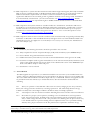
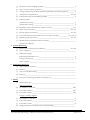
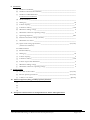
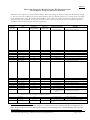
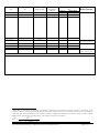
Sri Lanka: Renewable Energy for Rural Economic Development Project
SPECIFICATIONS FOR SOLAR HOME SYSTEMS AND SERVICE
STANDARDS
(Revised 7 January 2010)
1.
Solar Home System Hardware Description
1.1. A solar home system (SHS) is intended to provide the user with a convenient means of supplying power
for small electrical loads such as lights, a TV set and radio/cassette players. A typical SHS will provide
power for dc high efficiency luminaires (fluorescent or Light Emitting Diods (LED)), and 12 Vdc socket
outlets for TV or similar appliance for three to five hours a day. Additional 12 Vdc luminairs such as
night lamps or DC/AC inverters may be supplied as options. Each SHS shall consist of one or more
photovoltaic (PV) modules with an output of 10 Wp or more charging a 12 Vdc lead-acid battery, along
with related electronic and electrical components and mounting hardware. The SHS must have at least
one functional task or area light. The batteries, charge controller, low voltage disconnect and associated
components will be located in sturdy enclosure(s). Examples of SHS PV module sizes and typical service
levels provided with five peak sunlight hours per day are shown below:
SHS
10 Wp
30 Wp
60 Wp
Useful energy
3 Ah/day
9 Ah/day
18 Ah/day
Typical service levels
2½ hours per day for three 5W lights
3 hours per day for three 8W lights and a 12W TV
4 hours per day for five 8W lights and a 12W TV
Note: These are representative levels of service assuming 10% module derating and 20% battery round-trip Wh
losses. Actual operating hours per day will vary depending on the number and wattage of the lights and other
appliances switched on at any given time and peak hours of sunlight available on any given day.
1.2. The SHS components shall be packaged to provide convenient installation at a remote customer home
site by a supplier-trained technician. Systems that are fully integrated, i.e. “Plug and Play Systems” shall
be set-up by the customers themselves. The system shall be constructed such that a user can perform
routine maintenance such as adding battery water and replacing light bulbs and fuses, and a technician
can easily perform system diagnostics or replace components.
1.3. The supplier/dealer will provide the most appropriate system integration, components, assembly and
packaging that meet both the customers’ needs and all the specifications in Annex 1 - Solar Home
System Requirements. The specifications of the SHS should be summarised in Annex 2 - Solar Home
System Specification Sheet along with the required test certificates (see section 2 ). Any exceptions and
variations to the specifications must be explicitly stated the section titled Exceptions and Variations in
Annex 2. The scope and reasons for each listed exception and variation must be fully explained with
supporting data.
2. Certification Requirements
2.1 Products to be financed in the International Development Association (IDA) and Global Environment
Facility (GEF)-assisted Renewable Energy for Rural Economic Development (RERED) Project must
have a type-test certificate from a testing and certification organisation acceptable to the Government of
Sri Lanka and the World Bank stating that the Solar Home System meets or exceeds the specifications
given in Annex 1. Organisations accredited according to ISO/IEC 17025 (formerly ISO 25) or equivalent
standards will be acceptable1.
1
Test certificates from testing organizations accredited under IECEE NCB program will be accepted without the testing
Solar Home System Specifications and Service Standards – 7 January 2010
Sri Lanka Renewable Energy for Rural Economic Development Project
Page 1 of 4
2.2 SHS components or systems that bear the Photovoltaic Global Approval Program (PV GAP) or IECEE
Mark or Seal or certified according to PVRS standards will be acceptable for use in the Project without
additional certification requirements. PV GAP is a Geneva-based not-for-profit international
organisation dedicated to the sustained growth of global PV markets to meet energy needs worldwide in
an environmentally sound manner. (For more information visit: http://www.pvgap.org/). IECEE
(http://www.iecee.org/) has acquired the rights to PVRS standards and the issuance of PVGAP Mark
and Seal.
2.3 SHS components and systems which are accredited under the “Golden Sun” certification will also be
acceptable for use in the Project without additional certification requirements. “Golden Sun” is China’s
national certification scheme for PV products established under GEF and World Bank sponsored project
“Establishment of National Certification Program for PV Products”. A list of accredited products can be
found at http://www.cgc.org.cn/eng/news_show.asp?id=4
2.4 SHS components that have been tested in accordance with an internationally recognized (preferably IEC)
standard at an ISO/IEC 17025 accredited laboratory and approved for use in World Bank funded rural
electrification projects are eligible for use in the Project on a case-by-case review by the Administrative
Unit of the Project (AU).
3. Documentation
3.1. At a minimum, the following documents should be provided to the customer:
3.1.1. Duly completed Customer Acceptance Receipt (CAR) made mandatory by the RERED Project
3.1.2. User’s Manual along with maintenance instructions
3.1.3. Additional warranty information (if exceeds recommended minimum terms given in the CAR)
3.1.4. Customer Complaint Cards together with addresses of the relevant branch/dealer/franchisee, head
office of the supplier/dealer and contact details of the Administrative Unit of the RERED Project.
Such cards shall be simple to fill-in and post.
3.1.5. Technicians’ visit record card
3.2. User’s Manual
The SHS supplier must provide a User’s Manual intended for the customers (to be included with each
system). The User’s Manual provided to the user should be in the language the user is most familiar with.
The User’s Manual documentation should be simple and easy to understand. Sketches and graphics should
be provided to make the manual easy to understand and use. The documentation shall include the
following:
3.2.1 Theory of operation of the SHS with a discussion on: battery charging by the array; functions,
battery low voltage protection and battery overcharge protection. The relationship between energy
available on a daily basis and sunlight conditions should be clearly and simply explained.
3.2.1
A description of all user interactive hardware including disconnect switches and status indicators.
3.2.2
Procedures for proper system operation, including a list of load limitations and any problem
loads. Suggested operation, including load conservation during periods of inclement weather
and/or a low voltage disconnect event. The procedures for checking that the photovoltaic array
is not shaded and how to prevent shading must be explained. In the case of portable and Plug
and Play units, proper orientation of the PV panel must be explained to maximize energy
laboratory having to submit a copy of the ISO/IEC 17025 certificate. The list of NCBs and their CBTLs and ACTLs can be
found at http://members.iecee.org/iecee/ieceemembers.nsf/CBTLs?OpenView
Solar Home System Specifications and Service Standards – 7 January 2010
Sri Lanka Renewable Energy for Rural Economic Development Project
Page 2 of 4
generation. This should include a simple diagram of principle components of the system.
3.2.3
For user maintenance items (such as non-maintenance free batteries) proper maintenance
procedures of each item.
3.2.4
Actions which would void warranty
3.2.5
Procedures for emergency shut down and for extended periods of system non-use.
3.2.6
Personal and product safety measures to be practiced around the system “Do’s and Dont’s”
3.2.7
A trouble shooting guide for users.
3.3 Technician’s Manual for Installation, Operations and Maintenance
The SHS supplier must provide a Technician’s Manual for Installation, Operations and Maintenance (for
use by the service technicians). This manual provides specific details on installation, operation and
maintenance. It must be provided to the technician in a language best understood by the technician, and
shall include the following:
3.3.1
A detailed technical description of the system
3.3.2
A complete list of all system components, with associated manufacturers literature, specifications,
warranties and instances which would void manufacturers' warranty.
3.3.3
A complete copy of the User’s Manual.
3.3.4
Complete installation instructions.
3.3.5
A recommended post-installation acceptance test procedure “Checklist”, including all appropriate
set points and test procedures. They will include the following:
3.3.6
4
Verify that the installation of the photovoltaic array with regard to position, direction, inclination
and shading avoidance will maximise energy generation.
Ensure that the battery has received an equalisation charge just before installation.
Use a shunt to measure the current from the array under charging conditions to verify the array
charging current. This measurement should be done under clear sky conditions.
Test all the loads for proper operation.
Make system-wide voltage drop measurements in the sub-circuits to verify that connections are
within the maximum allowable voltage drop.
Note all measurements in the installation log.
Explain to the user the system operating principles, load management requirements, impact of
shading of the array and how to check and avoid it, user maintenance checks and how to
conduct them.
A recommended annual maintenance schedule, with complete maintenance instructions.
3.3.7
A detailed trouble-shooting guide referencing all the system components. This shall include
repairs and diagnostic procedures that can be done by the supplier or a qualified third party.
Repairs and procedures not to be attempted by non-electricians and/or electricians unfamiliar
with photovoltaic systems shall also be identified.
3.3.8
A functional block diagram, electrical single-line drawing showing the placement of all hardware
and ratings of all components and physical layout diagram.
3.3.9
Emergency shut down procedures.
Customer Service and Protection
4.1 The supplier/dealer shall educate the customer on proper usage of the SHS, the abilities and limitations of the
particular configuration the customer intends to purchase, and maintenance requirements prior to the sale of
the aforesaid system.
Solar Home System Specifications and Service Standards – 7 January 2010
Sri Lanka Renewable Energy for Rural Economic Development Project
Page 3 of 4
4.2 The supplier/dealer shall clearly explain to the customer the warranty terms associated with the SHS and
actions which would void the warranty.
4.3 The customer shall be provided with contact details of supplier/dealer, including that of branch offices and
head office. Contact details of the AU shall also be provided. It is preferable if such details can be printed or
reliably pasted onto a permanent fixture of the SHS (such as the Charge Controller).
4.4 Customer complaints shall be attended to within 3 working days from the date of receipt of complaint.
4.5 The supplier/dealer shall maintain adequate stocks of spares at his outlets for replacement of faulty
components.
4.6 For systems which are permanently affixed to the household, the supplier/dealer shall carry out a minimum of
four (4) free service visits at following intervals:
1st visit within 14 – 30 days from the date of installation.
2nd, 3rd, and 4th visits shall be at the end of the 4th, 8th and 12th month, from the date of installation,
respectively.
Any visit to the household based on customer complains during this period shall be counted under the
aforementioned 4 free visits.
4.7 At the end of the first year from the date of installation, the customer shall be given the option of entering
into an Annual Maintenance Contract (AMC) with the supplier/dealer. However the supplier/dealer shall
discuss the terms of such AMC with the customer at the point of installation. If the customer does not want
to enter into an AMC, the supplier/dealer shall charge the customer a fee for such visits.
4.8 In the case of Plug-and-Play and other forms of movable SHS systems, the customer shall bring the system to
the supplier/dealer or to an authorised service agent for repairs and maintenance work, as necessary.
Solar Home System Specifications and Service Standards – 7 January 2010
Sri Lanka Renewable Energy for Rural Economic Development Project
Page 4 of 4
Annex 1
SOLAR HOME SYSTEM REQUIREMENTS
1. General
1.1 (a) The supplier/dealer will provide a minimum twelve-month warranty against manufacturer’s defects
on all system-integrated parts and labour excluding fuses or end-use devices such as luminaires. On all
major individual components, manufacturer’s warranties will be passed through to the user. Specifically,
the PV modules should be warranted against reduction of output of no more than 10 percent of rated
capacity over a ten-year period. The battery, charge controller, low voltage disconnect, switches, and
charge indicators should be warranted for at least one year. Battery end-of-life will be determined when
the battery capacity down to 1.75 V/cell at 25 C drops to less than 80 percent of the initial rated capacity.
(b) In addition, the supplier/dealer will provide a 30-day money back guarantee for users who wish to
return the SHS for whatever reason, and the suppler/dealer will refund no less than 75 percent of the
selling price of the SHS when the module, controller, battery and light fixtures are returned to the
supplier/dealer in good working condition. All warranties will start from the day the system is accepted
by the user.
1.2 Nominal system voltage (rated voltage) shall be 12 V DC.
1.3 The entire SHS must be designed and constructed such that it requires maintenance and inspection by a
technician no more frequently than once every six months.
1.4 The main components shall be integrated in such a way as to allow replacement (in case of failure) with a
similarly functioning component of a newer design or a different brand. This will allow for future
component evolution or variability of future component availability.
1.5 With the exception of the PV module(s), the supplier shall deliver the system to the user with as many
components pre-assembled and pre-wired as is feasible prior to shipment.
1.6 All components, including spares, will undergo full bench testing at the supplier factory or the originating
source factory with proper documentation supplied. All set point voltages will be verified and
documented with the results dated and the records maintained at the suppliers facility.
2. Operating Environment
The entire system shall be designed and built to withstand the environmental conditions found in Sri
Lanka. For design purposes, consider that the temperature could range from zero to +40 C and
humidity levels could reach 100 percent. The PV array and support structure must be able to withstand
wind gusts up to 100 km/hour without damage. All wiring, enclosures, and fixtures that are mounted
indoors must be resistant to high humidity, corrosion and insect and dust intrusion. Use of corrosion
resistant terminals is required. Protection of the electronic circuit boards from corrosion by potting or
applying a conformal coating is recommended.
3. Photovoltaic Array
3.1. The photovoltaic array will consist of one or more flat-plate photovoltaic modules. Each module should
comprise no less than 36 series-connected single or poly-crystalline silicon solar cells. Flat plate thin-film
modules could also be used.
3.2 The photovoltaic array should have a peak power output of at least 10 Wp, under Standard Test
Conditions (STC) as defined in IEC 60904-1. The peak power output for thin film modules should be the
value after light soaking.
3.3.1
Photovoltaic modules bearing PV GAP mark or seal or the Chinese Golden Sun certification will be
accepted for use in the Project without additional requirements. Photovoltaic Modules tested to
PVRS standards at an ISO 17025 accredited laboratory will also be accepted. In the absence of above,
single-crystalline or poly-crystalline modules must be type tested and certified in accordance with IEC
Solar Home System Specifications and Service Standards – 7 January 2010
Sri Lanka Renewable Energy for Rural Economic Development Project
Annex 1
Page 1 of 8
61215 and thin-film photovoltaic modules must be type tested and certified in accordance with IEC
61646 or IEEE Specification 1262-1995. All modules must be manufactured in ISO9001 Quality
Management System accredited factories. For Photovoltaic modules of differing sizes made by the
same manufacturer using the same (i) production processes and construction methods, (ii) materials
and (iii) quality control procedures as a module already accepted for use under the Project, a
Manufacturers Self Compliance Certificate (MSCC) will be accepted2 in lieu of above requirements.
3.3.2
For modules of less than 20 Wp where such product certification is not available and a MSCC cannot
be furnished, qualification requirement is relaxed to passing the Outdoor Exposure, Humidity and
Robustness of Termination requirements as per IEC 61215 or 61646, and the said PV panel must be
manufactured in an ISO 9001 accredited manufacturing facility.
3.4 If more than one module is used, identical models shall be used and they shall be connected in parallel.
3.5 Each module must be clearly marked indicating: Manufacturer, Model Number, Serial Number, Peak Watt
Rating, Peak Current, Peak Voltage, Open Circuit Voltage and Short Circuit Current of each module.
3.6 The module junction box must be sealable and moisture resistant. If the module does not have a junction
box which allows for a direct connection, then the structure will have a weather resistant
junction/combiner box attached to the support structure. This box will have a terminal strip for connecting
the parallel-wired modules.
3.7 The modules must be framed in such a way as to allow secure connection to the module mounting
structure.
4. PV Array Mounting Structure
Note: This section applies to PV modules to be installed on a structure. It does not apply to portable units
and units to be set-up by the customer i.e. “plug and play units”
4.1 The array mounting structure will hold the photovoltaic module(s). The module(s) must be mounted to a
support structure made of aluminium, galvanised steel or other corrosion resistant material which assures
stable and secure attachment.
4.2 The structure must be mounted at a fixed angle and oriented to maximise the useful energy supplied to
the user during the design month (i.e., the month with the worst average daily insolation). Array
orientation must be adjustable in the field.
4.3 The structure will incorporate galvanised steel, aluminium, stainless steel or other corrosion resistant
hardware for all external connections. These include the modules to structure, structure to pole and pole
to building attachments.
4.4 The modules may be roof or ground-mounted:
(a) Roof-mounting: minimum clearance between the PV array and the roofing material must be
at least 10 cm. Anchoring of the mounting structure must be to the building and not to the
roofing material.
(b) Ground-mounting: A metal pole must be used with the module(s) attached at the top of the
pole. The module(s) must be at least 4 metres off the ground. The pole must be anchored in
concrete at least one metre deep in the ground. The pole and mounting structure must be
sufficiently rigid to prevent twisting in the wind or if large birds alight on the array.
5. Battery Storage
5.1. The rechargeable battery will preferably consist of one 12 V DC lead-acid battery, but no more than two
identical 12 V DC lead-acid batteries connected in parallel.
5.2. The battery ampere-hour (Ah) capacity should be such that it will permit a minimum of three days of
2
The MSCC Format is available for download at http://www.energyservices.lk/pdf/shs_selfcomp_08jul04.pdf
Solar Home System Specifications and Service Standards – 7 January 2010
Sri Lanka Renewable Energy for Rural Economic Development Project
Annex 1
Page 2 of 8
autonomy where the maximum depth of discharge is limited to 75 percent of rated capacity. It is
recommended that the battery be sized to permit five days of autonomy in regions where extended
cloudy periods are expected. However, over-sizing of the battery should be avoided as it can lead to
shortening of battery life due to insufficient charging.
For shallow cycle batteries such as modified automotive batteries, the 20-hour ampere hour (Ah) capacity
(C20) at 12Vdc measured at 250C should be such that it will permit a minimum of three days of autonomy
where the maximum depth of discharge is limited to 75 percent of rated capacity
Example: Minimum lead-acid battery capacity for typical applications
Minimum battery sizes (Ah) for
Module
Average daily Ah to
(Daily Ah x 3 days of
autonomy of
Rating (Wp)
load at 12 V DC
autonomy)/0.75
3 days
5 days
10
20
30
40
50
60
3
6
9
12
15
18
12
24
36
48
60
72
12
24
36
48
60
72
20
40
60
80
100
120
These are based on five peak sunlight hours per day, 10% module derating and 20% battery round-trip Wh losses (as per
paragraph 1 of Specifications).
5.3 The maximum permissible self discharge rate is 10 percent of rated capacity per month at 25 C.
5.4 Cycle life of the battery (i.e., before its residual life drops below 80 percent of the rated Ah capacity), at
25 C must exceed 200 cycles when discharged down to an average depth of discharge (DOD) of 75
percent.
5.5 Deep cycle batteries are preferred over modified automotive type shallow cycle batteries for use under the
Project. Batteries must be certified to test standards appropriate for each battery type.
5.5.1
Interim Battery Acceptance Short Test Procedure (IBASTP - given in Annex 3) with the
acceptance criteria being, battery capacity being not less than 100% of nominal C10 capacity after
5th C10 test, and battery capacity being not less than 95% of the nominal C10 capacity after the 6th
C10 test according to the test procedure laid out therein.
5.5.2
IEC 61427 (Ed. 2) “Secondary cells and batteries for photovoltaic energy systems”
(a) For flat plate batteries: after 3 test sequences (procedure defined under paragraphs 8.4.1, 8.4.2
and 8.4.3 of IEC 61427) the battery should retain at least 80% of its initial C10 capacity (as per
end-of-test conditions defined under paragraph 8.4.4 of IEC 61427).
(b) For tubular plate batteries: after 8 test sequences (procedure defined under paragraphs 8.4.1,
8.4.2 and 8.4.3 of IEC 61427) the battery should retain at least 80% of its initial C10 capacity
(as per end-of-test conditions defined under paragraph 8.4.4 of IEC 61427).
5.5.3
Batteries bearing the PV GAP Mark or having been tested and certified at an ISO 17025
accredited laboratory in accordance with PVGAP PVRS5A - Lead-acid Batteries for Solar
Photovoltaic Energy Systems – “General Requirements and Methods of Test for Modified
Automotive Batteries” will be accepted.
5.5.4
Also accepted are tubular plate batteries tested and certified in accordance with Indian Standard
IS 13369:1992 - Stationary Lead Acid Batteries (with Tubular Positive Plates) in Monobloc
Containers.
5.5.5
Batteries bearing Chinese Golden Sun certification will be accepted without additional
requirements
5.5.6
Accepted on an interim basis are flat plate batteries tested and certified in accordance with BS
Solar Home System Specifications and Service Standards – 7 January 2010
Sri Lanka Renewable Energy for Rural Economic Development Project
Annex 1
Page 3 of 8
EN 50342:2001 - Lead-acid Starter Batteries; General Requirements, Methods of Test and
Numbering (which supersedes BS EN 60095-1:1993), or equivalent or better standard.
Manufacturer's self compliance certificates for batteries tested to either BS EN 50342:2001 or BS
EN 60095-1:1993 received by the Administrative Unit, RERED Project after 30 September 2004
shall not be acceptable.
5.5.7
Other than the batteries already accepted for use under the Project as at September 2009, new
batteries not meeting IBASTP, PV GAP PVRS 5A, IEC 61427 or IS 13369:1992 shall not be
accepted.
5.5.8
For batteries of differing capacities made by the same manufacturer using the same (i) production
processes and construction methods, (ii) materials and (iii) quality control procedures as a battery
already accepted for use under the Project (subject to 5.5.7 above), a Manufacturers Self
Compliance Certificate (MSCC) will be accepted2 in lieu of above requirements.
5.6 The batteries shall be supplied to the customer in a fully charged condition ready for use. If the battery is
supplied dry charged, all chemicals and electrolyte must be supplied in accordance with battery
manufacturer’s specifications. The battery and associated containers should be able to handle transport
down rough dirt roads without damage.
6. Charge Regulator and Load Control
6.1 A solid-state photovoltaic charge controller must be provided. The charge controller must incorporate
one of the following charge control algorithms: (a) Constant Voltage, (b) Pulse Width Modulated, (c)
On/Off series or shunt linear. Voltage regulation (high voltage disconnect voltage) set points should
prevent excessive gassing of the battery. The set points must be factory pre-set with the set points
applicable to the specified battery characteristics. If on/off control algorithm is used, regulation voltage
of 14.4 V and a reconnect voltage of 13.4 V is recommended for flooded lead-acid batteries. It is
recommended that circuitry to allow boost or equalisation charging the battery be provided.
6.2 The charge controller must have some type of display to indicate when it is in the charging mode.
6.3 The charge controller must be capable of handling 125% of the array's rated short circuit current over a
one hour period, but not less than (a) 6 A when used with modules rated at 30 Wp or more, and (b) 3 A
when used with modules rated at less than 30 Wp.
6.4 The charge controller must be equipped with reverse current leakage protection. Blocking diodes or logic
derived methods are both acceptable. If blocking diodes are used they must exhibit a low forward voltage
drop.
6.5 Battery temperature compensation circuitry is not required if flooded lead-acid batteries are used.
However, if temperature compensation is not provided, then the set points must correspond to the type
of battery and the ambient temperature of the site where the SHS is to be used. Temperature
compensation is required if sealed lead-acid batteries are used.
6.6 The load must be controlled by a low voltage disconnect (LVD) device. The LVD must be capable of
handling at least 150 percent of the maximum expected continuous load (e.g., assuming all end use
devices are simultaneously on). It should be factory pre-set to disconnect and reconnect voltages
corresponding to the safe operation of the battery under ambient temperature conditions. For example, a
disconnect voltage of 11.7 V DC + 0.1 V DC and reconnect voltage of 12.9 V DC + 0.2 V DC is suitable
for safe operation of lead-acid batteries used in SHS. Discharge of automotive-type lead-acid batteries
below a depth of discharge of 75% of rated capacity should not be permitted
6.7 Maximum current draw of the controller, when no LEDs are lit should not exceed 10mA.
6.8 The charge regulator/controller must be protected against damage caused by short circuit of the input
and output terminals, and reverse polarity of connections. The controller shall have electronic or manual
circuit breaker capability for load inrush currents up to 10 times rated DC current lasting less than 10
microseconds. Such an inrush current shall not cause the load to be disconnected and shall not cause
Solar Home System Specifications and Service Standards – 7 January 2010
Sri Lanka Renewable Energy for Rural Economic Development Project
Annex 1
Page 4 of 8
degradation of the controller. Protective devices should disconnect the load should currents of 10 times
rated DC current last longer than 10 microseconds. Lightning induced surge protection must be provided.
6.9 Some means must be provided to safely disconnect the battery and the module during servicing or repair
by a technician.
6.10The model number, serial number, rated voltages and currents, set points and indicator settings should be
noted on the charge regulator case.
6.11Charge controllers bearing Chinese Golden Sun certification will be accepted by the Project without
additional requirements.
6.12 For charge controllers of differing current handling capabilities made by the same manufacturer using the
same (i) production processes and construction methods, (ii) materials and (iii) quality control procedures
as a battery already accepted for use under the Project (subject to 5.5.7 above), a Manufacturers Self
Compliance Certificate (MSCC) will be accepted2 in lieu of above requirements.
7. System Monitoring
7.1 Some form of a battery state-of-charge indicator must be provided on or near the controller or load
centre.
7.2 This device must, at a minimum, indicate when the battery condition is:
(a) Suitable to operate all loads (e.g. voltage greater than 12.5 V DC)
(b) Energy conservation required (e.g., battery voltage less than 11.9 V DC)
7.3 These indicators may be LEDs, or analog or digital meters.
7.4 The chosen device must come appropriately labelled such that the user does not have to refer to a manual
to understand the existing battery condition.
8. Equipment Enclosure
8.1. The equipment enclosure(s) will house the batteries, charge controller, charge indicators, low voltage
disconnect, and all interconnecting wiring. The enclosure(s) must not be installed in a location that could
be subject to flooding or be exposed to rain.
8.2. The batteries must be housed in a vented compartment. All parts of the compartment subject to battery
acid contact must be acid resistant. This compartment must be built strong enough to accommodate the
weight of the battery. This compartment must adequately support and vent wet, lead-acid batteries.
Access to the battery compartment by children must be prevented.
8.3. The remainder of the system components (electronics, switches etc.) must be housed in a separate
compartment or enclosures which prevents the system components being affected by battery acid spills
or fumes. The compartment or enclosure design must allow the internal electronic equipment to operate
within acceptable operating temperature limits. It must be weather, dust, and insect resistant.
8.4. The enclosure must be constructed of a durable material so as to last 10 years without maintenance.
9. Wiring
9.1. Stranded and flexible insulated copper wiring must be used. Minimum acceptable cross-section of the
wire in each of the following sub-circuits is as follows:
(a) From PV module to regulator/controller: 2.5 mm2
(b) From regulator/controller to battery: 2.5 mm2
Solar Home System Specifications and Service Standards – 7 January 2010
Sri Lanka Renewable Energy for Rural Economic Development Project
Annex 1
Page 5 of 8
(c) From controller to loads: 1.5 mm2
9.2 Notwithstanding the above minimum wire size requirements, all wiring must be sized to keep line
voltage losses to less than 5% in each sub-circuit and to allow the circuit to operate within the capacity
rating of the wire.
9.3 All exposed wiring (with the possible exception of the module interconnects) must be in conduits or be
firmly fastened to the building structure. Wiring through roofing, walls and other structures must be
protected through the use of bushings. Wiring through roofing must form a waterproof seal. Where the
wiring is through flammable material (e.g. thatched roofs), they must be in a metal conduit. Adequate
fasteners, conduits, bushings and other installation hardware must be supplied.
9.4 All wiring shall be colour coded and/or labelled.
9.5 Field-installed wiring must be joined using terminal strips or screw connectors. Soldering or crimping in
the field must be avoided. Wire nuts are not allowed. The rated current carrying capacity of the joint
must not be less than the circuit current rating. All connections must be made in junction boxes.
Fittings for lights, switches, and socket outlets may be used as junction boxes where practical.
10. Luminaires
Luminaires used in a PV system must be either Fluorescent or LED.
The following applies for Fluorescent Luminaires:
10.1 Minimum operating voltage when the tube light or compact fluorescent light (CFL) will still strike
shall be less than 85% of the rated voltage.
10.2 Maximum continuous operating voltage without damage to the circuit must be at least 125% of the
rated voltage.
10.3 The minimum operating frequency should be 20 kHz and the wiring length from the inverter to the
fluorescent light bulb must be kept short to minimise radio interference.
10.4 The electrical waveform on the fluorescent tube terminals must be symmetrical in time to within 10
percent (i.e., 60%/40% waveform maximum difference in symmetry over the voltage range of 11.0 to
12.5 V DC at an ambient temperature of 25 degrees C).
10.5 The maximum crest factor (ratio of maximum peak to RMS voltage of the waveform applied to the
fluorescent tube light) shall be less than 2.
10.6 The input connections to the inverter should prevent the application of voltage with reverse polarity,
or the inverter should be protected against damage when the rated voltage is applied with reverse
polarity.
10.7 The inverter should be protected against damage by the application of voltage under open circuit
conditions (e.g., when the light bulb is removed or has failed).
10.8 Lenses, covers, grids etc. (if used) must be easily removable by the user for bulb replacement or for
cleaning.
10.9 No blackening or reduction in the lumen output by more than 10% should be observed after 1,000
ON/OFF cycles (two minutes ON and four minutes OFF is one cycle).
10.10 The luminous efficacy of the light, inclusive of the power requirement of the inverter, must be either:
(a) greater than 30 lumens/watt with any reflectors, lenses, covers or grids (if used) in place; or (b)
greater than 35 lumens/watt without reflectors, lenses, etc in place.
10.11 Luminaires must be insect proofed and corrosion and weather resistant.
10.12 Luminaires must be marked with the manufacturer, model number, rated operating voltage, rated
current and date of manufacture or batch number.
Solar Home System Specifications and Service Standards – 7 January 2010
Sri Lanka Renewable Energy for Rural Economic Development Project
Annex 1
Page 6 of 8
The use of LED luminaires is allowed for area lighting, task lighting, and for use as night lights. Until such time a
proper standard for testing LED luminaires for off-grid applications becomes available, LED luminaires will be
allowed for area and task lighting in the Project subject to the following:
10.13
Lumen efficacy (lumen output (lm)/power consumption (W)) should exceed 70lm/W inclusive
of reflectors, diffusers and covers.
10.14
Lumen output after 2000 hours of operation of the luminaire should be at least 80 percent of
initial lumen output (i.e., initial lumen output is measured after a 20 minute initial burn-in period).
Note: LED lamps require electronic power management and/or thermal management design to
extend the life and retain the LED chip’s lumen output.
10.15
LED luminaires with integrated batteries (this is optional if you are going to support such lights)
10.15.1 Luminaires with integrated lead-acid or Li-ion rechargeable batteries should have
circuitry to prevent over charge and over discharge according to battery manufacturers
specifications. Luminaires with Ni-MH rechargeable batteries and PV module could use
passive PV charging. However, the charge current should be limited to a maximum of
2*I10 at a battery cell voltage of 1.4 V. Protection of Ni-MH batteries to prevent over
discharge to less than 0.8 V to 1 V is required.
10.15.2 Should provide at least 4 hours of lighting per charge for lamps that are recharged daily.
Luminaires designed for less frequent recharge should have appropriately larger battery
capacity (e.g., 4 hours per day for 7 day operation should have adequate battery capacity
to operate lamp for 28 hours before recharge).
10.16
The luminaire switches and connectors should be robust and capable of 1000 on-off switching
cycles.
10.17
The luminaire should be robust and all parts, connectors and wiring should not come apart.
10.18
The SHS supplier /dealer must provide at least a one year warranty against manufacturing defects
10.19
Minimum operating voltage shall be 85% of the rated voltage, and should be capable of
withstanding 125% of the rated voltage.
10.20
Luminaire must be insect, and corrosion and weather resistant.
10.21
Luminaire must be marked with the manufacturer, model number, rated operating voltage, rated
current. Luminaires with integrated batteries must be marked with the manufacturer, model
number.
10.22
Products that are already accredited for use under a World Bank group (IDA, GEF, IBRD, IFC)
funded rural electrification project or under the Lighting Africa Program
(http://www.lightingafrica.org) will be allowed for use under the Project without additional
requirements.
11. Plug and Play Systems
A “plug and play” PV system is a portable home lighting and appliance (radio/cassette/CD player etc.) that
can be set-up by the customer without assistance from a trained technician. The Project accepts inclusion of
such systems subject to following:
11.1 The said system should be certified under Chinese Golden Sun certification or an equivalent or better
standard accredited for use under a World Bank Group funded rural electrification project
11.2 The said system must have at least one functional task or area light
11.3 The system shall be warranted by the supplier/dealer for a period of 1 year from the date of purchase
against manufacturing defects (excluding fuses, and other safety devices).
11.4 The supplier/dealer must provide the customer with all necessary installation, maintenance and longevity
Solar Home System Specifications and Service Standards – 7 January 2010
Sri Lanka Renewable Energy for Rural Economic Development Project
Annex 1
Page 7 of 8
instructions along with instructions on proper orientation of the PV module, preferably with a
demonstration at the shop if the sustomer is to set-up the system.
11.5 The warranty on PV module shall be 5 years (a relaxation of condition 1.1 herein)
12. Socket Outlet
A 12 V DC and/ or lower voltage socket outlet used for a TV or similar appliance must be rated to carry the
maximum expected DC current. The outlet must be protected from reversing the polarity of the voltage
applied to the appliance.
13. Packaging and Delivery
13.1 In the case of fixed-base SHS systems, the supplier/dealer must assemble and wire the components into
integrated packaged SHS in accordance with the proposed design, and deliver the packaged SHS to the
user.
13.2 In the case of Plug and Play systems, it shall be pre-packaged to facilitate ease of transport and simple
installation by the customer.
13.3Each system must be packaged for shipping to prevent any shipping related damage. The supplier/dealer
will be responsible for settling any shipping related damaged claims and will be responsible for replacing
damaged systems in a timely manner.
13.4The modules must be packaged separately (not attached to the module support structure).
Solar Home System Specifications and Service Standards – 7 January 2010
Sri Lanka Renewable Energy for Rural Economic Development Project
Annex 1
Page 8 of 8
Annex 2
SOLAR HOME SYSTEM SPECIFICATION SHEET
1. Photovoltaic Module(s)
(a) Model Number _______________________________________________________
(b) Type (a-Si, crystalline Si,.etc.) _____________________________________________
(c) Number of cells in series ________________________________________________
(d) Rated peak power (Pmax) ____________________________________________ Wp
(e) Open circuit voltage _________________________________________________ V
(f)
Short circuit Current _________________________________________________ A
(g) V max ____________________________________________________________ V
(h) I max_____________________________________________________________ A
(i)
NOCT ________________________________________________________ deg C
(j)
Test Certification Standard ______________________________________________
(k) Test Laboratory _______________________________________________________
(Attach I-V curve and copy of test certificate)
2. Support Structure
(a) Type ______________________________________________________ (roof/pole)
(b) Material _____________________________________________________________
3. Battery Storage
(a) Model Number _______________________________________________________
(b) Number of batteries ___________________________________________________
(c) Rated voltage_______________________________________________________ V
(d) Structure and material of positive plate _____________________________________
(e) Capacity per battery at C/20 down to 1.75V/cell __________________________ Ah
(f)
Self discharge rate ____________________________________________ (%/month)
(g) Cycle life down to 75 percent of DOD _____________________________________
(h) Positive plate thickness ______________________________________________ mm
(i)
Negative plate thickness _____________________________________________ mm
(j)
Electrolyte volume ________________________________________________ litres
(k) Certified to standard: _________________________________: ________ (Yes/No)
(Attach test certificate)
4. Charge Regulator and Load Control
(a) Model number________________________________________________________
(b) Rated voltage_______________________________________________________ V
(c) Control algorithm _____________________________________________________
(d) High voltage disconnect
(i) Voltage regulation set point (Vr) ______________________________________ V
(ii) Reconnect voltage (Vrr) ____________________________________________ V
(e) Boost charging method _________________________________________________
(f)
Charge indicator? ______________________________________________ Yes/No
Solar Home System Specifications and Service Standards – 7 January 2010
Sri Lanka Renewable Energy for Rural Economic Development Project
Annex 2
Page 1 of 3
(g) Maximum current handling capability ____________________________________ A
(h) Type of current leakage protection ________________________________________
(i)
Voltage drop between module and battery terminals at controller/regulator _______ V
(j)
Temperature compensation? ______________________________________ Yes/No
(k) LVD maximum current handling capability ________________________________ A
(l)
LVD set points
(i) Disconnect voltage ________________________________________________ V
(ii) Reconnect voltage ________________________________________________ V
(m) Maximum current draw when no LED’s are not lit _________________________ mA
(n) Short circuit protection? _________________________________________ Yes/No
(o) Reverse polarity protection? ______________________________________ Yes/No
(p) Over current protection (inrush current at 10 microseconds)? ___________ Yes/No, A
(q) Lightning surge protection? _______________________________________ Yes/No
(r)
Module/battery/loads disconnection method ________________________________
(Attach test certificate)
5. System Monitoring
(a) Battery state-of-charge meter/indicator? _____________________________ Yes/No
(b) Type of indicator ______________________________________________________
(c) Indications settings
Fully Charged Suitable to Use __________________________________________ V
Energy Conservation _________________________________________________ V
Other (explain) _______________________________________________________
6. Equipment Enclosure
(a) Type of battery enclosure _______________________________________________
(b) Material _____________________________________________________________
(c) Type of controller housing ______________________________________________
(d) Material _____________________________________________________________
(e) Protection method against battery acid/fumes etc. ____________________________
7. Wiring
(a) Wire material type _____________________________________________________
Wire cross-sections
(b) PV module to controller ____________________________________________ mm2
(c) Controller to battery _______________________________________________ mm2
(d) Controller to loads ________________________________________________ mm2
Lengths of wiring supplied
(e) PV module to controller ______________________________________________ m
(f)
Controller to battery _________________________________________________ m
(g) Controller to loads __________________________________________________ m
(h) Wiring identification method (colour coded/labelled) _________________________ .
Solar Home System Specifications and Service Standards – 7 January 2010
Sri Lanka Renewable Energy for Rural Economic Development Project
Annex 2
Page 2 of 3
8. Luminaire
(a) Number of luminaire ___________________________________________________
(b) Number of fluorescent luminaires _________________________________________
(c) Number of LED luminaires _____________________________________________
For fluorescent Luminares:
(d) Model number(s) ______________________________________________________
(e) Wattage(s) _________________________________________________________ W
(f)
Lumen output(s) _____________________________________________________ L
(g) Luminous efficacy _________________________________________________ L/W
(h) Minimum striking voltage _____________________________________________ V
(i)
Maximum continuous operating voltage __________________________________ V
(j)
Operating frequency ________________________________________________kHz
(k) Electrical waveform voltage symmetry _____________________________________
(l)
Maximum crest factor __________________________________________________
(m) Open circuit voltage protection? __________________________________ (Yes/No)
(Attach test certificate)
For LED Luninares
(n) Model number(s) ______________________________________________________
(e) Wattage(s) _________________________________________________________ W
(f)
Lumen output(s) _____________________________________________________ L
(g) Luminous efficacy _________________________________________________ L/W
(h) Lumen output after 2000 hours __________________________________________ L
(i)
Minimum striking voltage _____________________________________________ V
(j)
Maximum continuous operating voltage __________________________________ V
9. Socket Outlet
(a) 12 V DC socket outlet? ________________________________________ (Yes/No)
(b) Reverse polarity protection? _____________________________________ (Yes/No)
(c) 6 and/or 9 V outlet? ____________________________________________ (Specify)
10. Other Components/Plug and Play Systems/Features
(a)
(b)
(c)
(d)
11. Exceptions and Variations to the Specifications Taken and Explanations
Solar Home System Specifications and Service Standards – 7 January 2010
Sri Lanka Renewable Energy for Rural Economic Development Project
Annex 2
Page 3 of 3
Annex 3
Renewable Energy for Rural Economic Development Project
Interim Battery Acceptance Short Test Procedure
Perform the test sequence as given below in Table 1 while maintaining the battery temperature between 20-25 deg
C. The tests must be conducted on at least three batteries that are randomly selected, at a testing center acceptable
to the Administrative Unit. Record the data in Table 2. If the results are within 10 percent for the three batteries,
then the results are acceptable. In case the deviations in the results are more than 10%, two additional batteries
should be tested to achieve better statistical significance.
Table 1 Interim Battery Acceptance Short Test Procedure
Capacity
test No.
Step
Current/
voltage Setting
I
n
i
t
i
a
l
Current/
voltage Limit
+
End-of-step Criteria
Remarks
U=2.4 V/cell
Constant current charging
Duration 8 hours
U<1.8 V/cell
I hour
U=2.4 V/cell
Duration 8 hours
U<1.8 V/cell
I hour
Constant voltage charging.
I
1
0
c
h
a
r
g
e
1. C10 Test
2. C10 Test
3. C10 Test
4. C10 Test
Initial charge
1st discharge
Rest Period
1st recharge
1st recharge
2nd discharge
Rest Period
2nd recharge
2nd recharge
3rd discharge
Rest Period
3rd recharge
3rd recharge
4th discharge
4th recharge
4th recharge
2.4 V/cell
-I10
0A
+ I10
2.4 V/cell
-I10
0A
+ I10
2.4 V/cell
-I10
0A
+ I10
2.4 V/cell
-I10
+ I10
2.4 V/cell
+ I10
+ I10
+ I10
+ I10
+ I10
Duration 8 hours
U<1.8 V/cell
I hour
U=2.4 V/cell
Duration 8 hours
U<1.8 V/cell
U=2.4 V/cell
Gradient of current is 0
A/s, but maximum 36
hours 3
Battery on open circuit
Constant current charging
Constant voltage charging.
Battery on open circuit
Constant
U current charging
=
2
.
4
V
/
c
e
l
l
Constant voltage charging
Battery on open circuit
Constant current charging
Constant voltage charging
Constant current charging
Constant voltage charging
Alternative for 4th recharge depending on availability of equipment
4th
recharge
4th recharge
4th recharge
3
+ I10
2.4 V/cell
0.1 x I10
+ I10
U=2.4 V/cell
Constant current charging
I < 0.1 x I10
Constant voltage charging
Capacity charged in 4th recharge > 112% of capacity discharged during 4th
discharge
Note that the end of the constant voltage charging is reached only when the battery current has not changed for two
hours. If this criterion has not been reached after 36 hours of the charging process, continue with the next step of the
test procedure.
Solar Home System Specifications and Service Standards – 7 January 2010
Annex 3
Sri Lanka Renewable Energy for Rural Economic Development Project
Page 1 of 3
Table 1 Interim Battery Acceptance Short Test Procedure
Capacity
test No.
5. C10 Test
Step
5th discharge
Rest Period
5th recharge
5th recharge
6. C20 discharge
Rest Period
Current/
voltage Setting
-I10
0A
+ I10
2.4 V/cell
-0.5 x I10
0A
6
Current/
voltage Limit
End-of-step Criteria
U<1.8 V/cell
I hour
U=2.4 V/cell
Duration 8 hours
U< 1.8 V/cell
I hour
U=2.4 V/cell
+ I10
+
Remarks
Battery on open circuit
Constant current charging
Constant voltage charging
Battery on open circuit
Constant current charging
t
I
h
1
r
e
c
h
a
r
g
e
6. C10 Test
6th recharge
7. C100 discharge
Rest Period
7th recharge
7th recharge
8. C5 discharge
Rest Period
8th recharge
8th recharge
9th discharge
Rest Period
9th recharge
9th recharge
2.4 V/cell
-0.1 x I10
0A
+ I10
2.4 V/cell
-2 x I10
0A
+ I10
2.4 V/cell
- I10
0A
+ I10
2.4 V/cell
0
+ I10
+ I10
+ I10
+ I10
Duration 8 hours
U< 1.8 V/cell
I hour
U=2.4 V/cell
Duration 8 hours
U< 1.8 V/cell
I hour
U=2.4 V/cell
Duration 8 hours
U< 1.8 V/cell
1 hour
U=2.4 V/cell
Duration 8 hours
Constant voltage charging
Battery on open circuit
Constant current charging
Constant voltage charging
Battery on open circuit
Constant current charging
Constant voltage charging
Battery on open circuit
Constant current charging
Constant voltage charging
Table 2
Renewable Energy for Rural Economic Development Project
BATTERY TEST REPORT
Interim Battery Acceptance Short Test
Battery Company:
Brand & Model Number:
Samples obtained from:
Battery type: (Select type)
Flooded / VRLA / AGM / Tubular /
Flat plate
Battery rated voltage:
Date Samples collected:
For Flooded battery, select one:
a) Battery filled onsite
b) Battery obtained fully charged
Nominal Ah Rating C20
Nominal Ah Rating C10
Testing Period:
Start date:
End date:
Testing Engineer (name):
Approved by (name and designation):
No. of samples.
Signature & Date:
Signature & Date:
Solar Home System Specifications and Service Standards – 7 January 2010
Sri Lanka Renewable Energy for Rural Economic Development Project
Annex 3
Page 2 of 3
Discharge Capacity
Test
1. C10 Test
2. C10 Test
Discharging Current
(A)
1 x I10 =
1 x I10 =
3
End-of-Discharge
Voltage (V/cell)
Battery
Temperature
(deg C)
Measured & Corrected Capacity4
(Ah)
Average
Max/Min*
Pass Criteria
1.80
1.80
1
1
.
x
C
1
I
0
1
.
8
0
0
T
e
s
t
=
4. C10 Test
5. C10 Test
1 x I10 =
1 x I10 =
1.80
1.80
C20 Test
C100 Test
C5 Test
6. C10 Test
0.5 x I10 =
0.1 x I10 =
2 x I10 =
1 x I10 =
1.80
1.80
1.70
1.80
Measured Capacity ≥
100% Nominal Capacity
Measured Capacity ≥
95% Nominal Capacity
* Maximum and minimum values for the batteries (at least three) represented in “average” value.
Comments:
4
Depending on the battery temperature (or ambient temperature in the laboratory during the tests) a correction of the
capacity is necessary if the temperature deviates by more than 3 degrees from 25°C. A correction factor of 0.6% per degree is
commonly used (see formula below). The formula is valid for temperatures between 10 and 35°C. The pass criteria must be
fulfilled for the temperature corrected values. The capacity correction is as follows:
25 C
10
C
C10Tmeasured
1 0.006 (Tmeasured 25 C )
Solar Home System Specifications and Service Standards – 7 January 2010
Sri Lanka Renewable Energy for Rural Economic Development Project
Annex 3
Page 3 of 3